EP3665094B1 - Trinkflasche - Google Patents
Trinkflasche Download PDFInfo
- Publication number
- EP3665094B1 EP3665094B1 EP18756393.7A EP18756393A EP3665094B1 EP 3665094 B1 EP3665094 B1 EP 3665094B1 EP 18756393 A EP18756393 A EP 18756393A EP 3665094 B1 EP3665094 B1 EP 3665094B1
- Authority
- EP
- European Patent Office
- Prior art keywords
- bottle
- drinking
- parts
- axis
- opening
- Prior art date
- Legal status (The legal status is an assumption and is not a legal conclusion. Google has not performed a legal analysis and makes no representation as to the accuracy of the status listed.)
- Active
Links
Images


Classifications
-
- B—PERFORMING OPERATIONS; TRANSPORTING
- B65—CONVEYING; PACKING; STORING; HANDLING THIN OR FILAMENTARY MATERIAL
- B65D—CONTAINERS FOR STORAGE OR TRANSPORT OF ARTICLES OR MATERIALS, e.g. BAGS, BARRELS, BOTTLES, BOXES, CANS, CARTONS, CRATES, DRUMS, JARS, TANKS, HOPPERS, FORWARDING CONTAINERS; ACCESSORIES, CLOSURES, OR FITTINGS THEREFOR; PACKAGING ELEMENTS; PACKAGES
- B65D11/00—Containers having bodies formed by interconnecting or uniting two or more rigid, or substantially rigid, components made wholly or mainly of plastics material
- B65D11/02—Containers having bodies formed by interconnecting or uniting two or more rigid, or substantially rigid, components made wholly or mainly of plastics material of curved cross-section
- B65D11/04—Bottles or similar containers with necks or like restricted apertures designed for pouring contents
-
- A—HUMAN NECESSITIES
- A45—HAND OR TRAVELLING ARTICLES
- A45F—TRAVELLING OR CAMP EQUIPMENT: SACKS OR PACKS CARRIED ON THE BODY
- A45F3/00—Travelling or camp articles; Sacks or packs carried on the body
- A45F3/16—Water-bottles; Mess-tins; Cups
- A45F3/18—Water-bottles; Mess-tins; Cups of rigid material
-
- B—PERFORMING OPERATIONS; TRANSPORTING
- B65—CONVEYING; PACKING; STORING; HANDLING THIN OR FILAMENTARY MATERIAL
- B65D—CONTAINERS FOR STORAGE OR TRANSPORT OF ARTICLES OR MATERIALS, e.g. BAGS, BARRELS, BOTTLES, BOXES, CANS, CARTONS, CRATES, DRUMS, JARS, TANKS, HOPPERS, FORWARDING CONTAINERS; ACCESSORIES, CLOSURES, OR FITTINGS THEREFOR; PACKAGING ELEMENTS; PACKAGES
- B65D47/00—Closures with filling and discharging, or with discharging, devices
- B65D47/04—Closures with discharging devices other than pumps
- B65D47/06—Closures with discharging devices other than pumps with pouring spouts or tubes; with discharge nozzles or passages
-
- B—PERFORMING OPERATIONS; TRANSPORTING
- B65—CONVEYING; PACKING; STORING; HANDLING THIN OR FILAMENTARY MATERIAL
- B65D—CONTAINERS FOR STORAGE OR TRANSPORT OF ARTICLES OR MATERIALS, e.g. BAGS, BARRELS, BOTTLES, BOXES, CANS, CARTONS, CRATES, DRUMS, JARS, TANKS, HOPPERS, FORWARDING CONTAINERS; ACCESSORIES, CLOSURES, OR FITTINGS THEREFOR; PACKAGING ELEMENTS; PACKAGES
- B65D47/00—Closures with filling and discharging, or with discharging, devices
- B65D47/04—Closures with discharging devices other than pumps
- B65D47/20—Closures with discharging devices other than pumps comprising hand-operated members for controlling discharge
- B65D47/2018—Closures with discharging devices other than pumps comprising hand-operated members for controlling discharge comprising a valve or like element which is opened or closed by deformation of the container or closure
- B65D47/2056—Closures with discharging devices other than pumps comprising hand-operated members for controlling discharge comprising a valve or like element which is opened or closed by deformation of the container or closure lift valve type
- B65D47/2081—Closures with discharging devices other than pumps comprising hand-operated members for controlling discharge comprising a valve or like element which is opened or closed by deformation of the container or closure lift valve type in which the deformation raises or lowers the valve port
-
- B—PERFORMING OPERATIONS; TRANSPORTING
- B65—CONVEYING; PACKING; STORING; HANDLING THIN OR FILAMENTARY MATERIAL
- B65D—CONTAINERS FOR STORAGE OR TRANSPORT OF ARTICLES OR MATERIALS, e.g. BAGS, BARRELS, BOTTLES, BOXES, CANS, CARTONS, CRATES, DRUMS, JARS, TANKS, HOPPERS, FORWARDING CONTAINERS; ACCESSORIES, CLOSURES, OR FITTINGS THEREFOR; PACKAGING ELEMENTS; PACKAGES
- B65D51/00—Closures not otherwise provided for
- B65D51/18—Arrangements of closures with protective outer cap-like covers or of two or more co-operating closures
-
- F—MECHANICAL ENGINEERING; LIGHTING; HEATING; WEAPONS; BLASTING
- F16—ENGINEERING ELEMENTS AND UNITS; GENERAL MEASURES FOR PRODUCING AND MAINTAINING EFFECTIVE FUNCTIONING OF MACHINES OR INSTALLATIONS; THERMAL INSULATION IN GENERAL
- F16K—VALVES; TAPS; COCKS; ACTUATING-FLOATS; DEVICES FOR VENTING OR AERATING
- F16K1/00—Lift valves or globe valves, i.e. cut-off apparatus with closure members having at least a component of their opening and closing motion perpendicular to the closing faces
- F16K1/12—Lift valves or globe valves, i.e. cut-off apparatus with closure members having at least a component of their opening and closing motion perpendicular to the closing faces with streamlined valve member around which the fluid flows when the valve is opened
- F16K1/123—Lift valves or globe valves, i.e. cut-off apparatus with closure members having at least a component of their opening and closing motion perpendicular to the closing faces with streamlined valve member around which the fluid flows when the valve is opened with stationary valve member and moving sleeve
-
- B—PERFORMING OPERATIONS; TRANSPORTING
- B65—CONVEYING; PACKING; STORING; HANDLING THIN OR FILAMENTARY MATERIAL
- B65D—CONTAINERS FOR STORAGE OR TRANSPORT OF ARTICLES OR MATERIALS, e.g. BAGS, BARRELS, BOTTLES, BOXES, CANS, CARTONS, CRATES, DRUMS, JARS, TANKS, HOPPERS, FORWARDING CONTAINERS; ACCESSORIES, CLOSURES, OR FITTINGS THEREFOR; PACKAGING ELEMENTS; PACKAGES
- B65D2251/00—Details relating to container closures
- B65D2251/0003—Two or more closures
- B65D2251/0006—Upper closure
- B65D2251/0015—Upper closure of the 41-type
-
- B—PERFORMING OPERATIONS; TRANSPORTING
- B65—CONVEYING; PACKING; STORING; HANDLING THIN OR FILAMENTARY MATERIAL
- B65D—CONTAINERS FOR STORAGE OR TRANSPORT OF ARTICLES OR MATERIALS, e.g. BAGS, BARRELS, BOTTLES, BOXES, CANS, CARTONS, CRATES, DRUMS, JARS, TANKS, HOPPERS, FORWARDING CONTAINERS; ACCESSORIES, CLOSURES, OR FITTINGS THEREFOR; PACKAGING ELEMENTS; PACKAGES
- B65D2251/00—Details relating to container closures
- B65D2251/0003—Two or more closures
- B65D2251/0068—Lower closure
- B65D2251/0087—Lower closure of the 47-type
Definitions
- Drinking bottles usually have a bottle body with an interior for holding a drink, which can be dispensed, for example, through a drinking spout.
- a drink which can be dispensed, for example, through a drinking spout.
- the drinking person lifts the bottom of the drinking bottle so far that the drink can flow through the drinking spout.
- the person drinking tilts their head back.
- Such a drinking position is not only uncomfortable, because the further your head is tilted back, the more uncomfortable it becomes to swallow.
- Such a drinking position can also pose dangers, for example if a cyclist who drinks while driving can only see the road out of the corner of his eye.
- KR 1998-0025702 U describes a bottle with a bellows that allows the bottle to be deformed.
- EP 0 891 762 A2 describes a holder with several components that can be moved relative to one another, with a drinking bottle being able to be inserted into the holder.
- the US 2015/0144584 A1 describes a feeding bottle device, with a holder for an elastic bottle bag consisting of two mutually movable parts.
- the task is to provide a drinking bottle that allows a user to have a particularly comfortable drinking position.
- the drinking bottle then comprises a first bottle part and a second bottle part.
- Both bottle parts each include an interior, the interior being designed to hold and store a liquid, namely a drink.
- the second Bottle part further includes a bottle opening.
- the bottle opening is designed to deliver the drink to a user of the drinking bottle.
- the bottle opening is or includes, for example, a drinking opening, in particular a drinking spout. It is envisaged that the interior spaces of the two bottle parts are or can be brought into fluid communication with one another. The drink can flow from one of the two bottle parts into the other of the two bottle parts and vice versa. It is provided that the drinking bottle has at least one configuration in which the two bottle parts run obliquely and/or at an angle to one another and/or are aligned.
- an axis of symmetry of the first bottle part can be aligned obliquely to an axis of symmetry of the second bottle part.
- the bottle opening is arranged coaxially to the axis of symmetry of the second bottle part.
- the two bottle parts can be rotated relative to one another about an axis of rotation.
- the oblique alignment of the bottle parts to one another makes a particularly comfortable drinking position possible, because while the second bottle part with the bottle opening is held at a pleasantly flat angle to the mouth, the first bottle part can be held upright at a steeper angle so that the drink can be dispensed quickly can be.
- the two bottle parts can be separate pieces of material or, alternatively, can be formed in one piece with one another.
- the drinking bottle has an upright configuration in which the two bottle parts are arranged upright, in particular are not aligned obliquely to one another. It is envisaged that the two bottle parts are in fluid communication with one another in both configurations (the inclined and the upright), and in particular it can be provided that the two bottle parts are always in fluid communication with one another.
- the drinking bottle includes the rotary or pivoting connection between the bottle parts, through which the two bottle parts can be rotated or pivoted relative to one another about the axis of rotation. It is provided that the axis of rotation is aligned obliquely to at least one of the two bottle parts, optionally to both bottle parts.
- the first bottle part includes a connecting piece and the second bottle part includes a connecting piece.
- the interior spaces of the bottle parts can be or can be brought into fluid communication with one another via the connecting pieces.
- the two bottle parts can be attached to one another through the connecting pieces.
- the oblique orientation of the axis of rotation allows the drinking bottle to be rotated from an upright configuration to an angled configuration.
- the two bottle parts are aligned (in particular coaxially) with one another, for example. This enables the drinking bottle to be transported and/or stored in the usual way.
- the angled configuration the extend both bottle parts at an angle (greater than 0 degrees and less than 180 degrees) to each other. A particularly comfortable drinking position is possible in the angled configuration.
- the drinking bottle can be transferred from the upright configuration to the angled configuration by rotating the two bottle parts relative to one another by 180 degrees around the axis of rotation.
- the interior of the first bottle part and the interior of the second bottle part together form the volume of the drinking bottle.
- the interior spaces of the two bottle parts can be of different sizes or (essentially) the same size.
- each of the interior spaces of both bottle parts each contributes at least 10%, at least 20% or at least 30% to the capacity of the drinking bottle.
- At least one of the two bottle parts is elongated along a longitudinal axis.
- the drinking bottle forms the longitudinal axis in at least one configuration, in particular in the upright configuration.
- the axis of rotation runs obliquely to the longitudinal axis.
- the angle between the rotation axis and the longitudinal axis is, for example, between 20 and 60 degrees, in particular between 30 and 40 degrees. This makes angled configurations with a particularly comfortable drinking position possible.
- the first bottle part includes a base, with the smallest distance between the base and the bottle opening being changeable by rotating the two bottle parts relative to one another.
- the smallest distance between the bottom and the bottle opening is maximum in the upright configuration of the drinking bottle and minimum in the angled configuration of the drinking bottle.
- At least one of the two bottle parts can be cylindrical in shape at least in one section and have a cylinder axis.
- the cylinder axis preferably runs coaxially to the longitudinal axis and/or defines the longitudinal axis of the respective bottle part.
- a circular-cylindrical shape is possible, although cylinders with cross-sectional shapes that deviate from a circle are also conceivable.
- the cylindrical shape can be cut off at an angle.
- the first bottle part may include a roof section on which the connecting piece of the first bottle part is formed.
- the roof section extends, for example, in a plane perpendicular to the axis of rotation.
- the first bottle part comprises a base, which can in particular run obliquely to the roof section, preferably at the same angle that is formed between the axis of rotation and the longitudinal axis.
- the roof section faces the ground. For example, the ground lies in a plane perpendicular to the longitudinal axis.
- the second bottle part may include a bottom portion that extends adjacent and parallel to the roof portion of the first bottle part.
- the floor section can be supported on the roof section.
- the pivot or rotary connection can be formed by the connecting pieces of the two bottle parts.
- the connecting pieces can therefore provide both the fluid connection and the pivot or rotary connection.
- the two connecting pieces together optionally form a screw connection. This allows for easy installation of the drinking bottle as well as secure rotation and holder.
- the bottle opening is preferably closed in a liquid-tight manner by means of a bottle cap.
- a valve serving as a bottle closure is arranged at the bottle opening.
- the valve comprises, for example, a base that is connected or connectable to the drinking bottle, a pin projecting from the base, the diameter of which (perpendicular to a longitudinal direction of the pin) increases from the base towards an end of the pin facing away from the base up to a final diameter, in particular continuously at least in sections.
- the valve further comprises a closure plate that is movable with respect to the pin and has an opening with an opening diameter. The opening diameter is smaller or equal to the final diameter of the pin.
- the valve further comprises a spring-elastic element which is supported on the base or near the base and biases the closure plate with a spring force into a closed position in which the opening is closed by the pin in such a way that the drink does not leak out of the bottle can escape from the valve. It is intended that the closure plate comes out of the Closing position can be moved out against the spring force of the resilient element into an open position, in which the opening of the closure plate is at least partially released.
- the released opening cross section corresponds to the cross section of the opening of the closure plate minus the cross section of the pin at the location of the closure plate.
- This valve enables a particularly comfortable delivery of the drink from the drinking bottle by placing the valve in the mouth.
- one-handed handling is possible by placing the drinking bottle with the valve on the mouth and simply pressing it against the mouth to dispense the drink.
- the valve can serve as a drinking nozzle.
- this valve ensures that no drink accidentally escapes from the drinking bottle when you turn the drinking bottle and hold the drinking bottle in the rotated position in which the bottom of the bottle is higher than the bottle opening.
- the valve optionally comprises an outer ring which surrounds the pin from the outside in a circumferential direction, the pin protruding beyond the outer ring in the axial direction of the pin.
- the outer ring and the pin are aligned coaxially with one another.
- the outer ring protects the resilient element and can provide a stop for the open position.
- the valve comprises a hose that surrounds the pin, in particular receives it, and extends through the opening of the closure plate.
- This tube can serve as a drinking tube and make it easier for a user to drink from the drinking bottle.
- the hose is, for example, flexible. It can be provided that the closure plate presses the hose against the pin in the closed position, so that the drinking bottle is closed in a liquid-tight manner.
- a valve for a drinking bottle is also described.
- Such a valve for a drinking bottle in particular for a drinking bottle according to any embodiment described herein, comprises a base that is connected or connectable to the drinking bottle, a pin projecting from the base, the diameter of which extends up to an end of the pin facing away from the base one End diameter increased (in particular at least in sections continuously), a closure plate movable with respect to the pin, which has an opening with an opening diameter that is smaller or equal to the end diameter of the pin, and a resilient element which is supported on the base and the closure plate with a Spring force is biased into a closed position in which the opening is closed by the pin.
- the closure plate can be moved out of the closure position against the spring force of the spring-elastic element into an open position in which the opening of the closure plate is at least partially released.
- This valve enables a particularly comfortable delivery of the drink from the drinking bottle by placing the valve in the mouth.
- one-handed handling is possible by placing the drinking bottle with the valve on the mouth and simply pressing it against the mouth to dispense the drink.
- the valve can be designed as previously described in connection with the drinking bottle.
- Fig. 1A shows an upright drinking bottle 1A with two bottle parts, namely a lower first bottle part 10 and an upper second bottle part 11.
- the drinking bottle 1A is used to store and deliver a drink G to a user.
- a bottom 102 of the drinking bottle 1A is formed on the first bottle part 10.
- a bottle opening 13 of the drinking bottle 1A is formed on the second bottle part 11. In the in Fig. 1A In the configuration shown, the base 102 and the bottle opening 13 are arranged at opposite longitudinal ends of the drinking bottle 1A.
- the first bottle part 10 comprises a circumferential wall 103. Together with the base 102 and a roof section 104 opposite the base 102, the wall 103 defines an interior 100.
- the interior 100 is designed to hold a liquid, in this case the beverage G.
- the second bottle part 11 also includes a circumferential wall 115.
- the bottle opening 13 is closed by a valve 2.
- the valve 2 serves as a drinking nozzle and can be opened by the user of the drinking bottle 1A.
- the valve 2 is protected by a cover 15 covering the valve 2.
- the walls 103, 115 of the two bottle parts 10, 11 are essentially cylindrical, in this case circular cylindrical, although other shapes are also conceivable.
- the cylinder axes of the two bottle parts 10, 11 run coaxially to one another.
- Each of the two bottle parts 10, 11 comprises a connecting piece 101A, 111A, in the present case each with a thread.
- the thread of the connecting piece 101A of the first bottle part 10 is engaged with the thread of the connecting piece 111A of the second bottle part 11.
- Both connecting pieces 101A, 111A are designed in the form of a socket, with one of the two connecting pieces 101A, 111A (here that of the second bottle part 11) being received by the other connecting piece 101A, 111A.
- the two interior spaces 100, 110 of the bottle parts 10, 11 are in fluid communication with one another, so that with a corresponding inclination of the drinking bottle 1A, the drink G can flow from the first into the second bottle part 10, 11 and vice versa.
- a seal 14 arranged (all around) between the connecting pieces 101A, 111A prevents the beverage from escaping unintentionally at the connecting sections 101A, 111A.
- the drink can be dispensed from the drinking bottle 1A when the valve 2 is open. In the in Fig. 1A In the configuration shown, this can lead to an uncomfortable drinking position with the head thrown far back, especially when the drink G is running low.
- the drinking bottle 1A has a pivot connection S.
- the pivot connection S is formed in the present case by the two connecting pieces 101A, 111A of the bottle parts 10, 11, specifically by their threads that engage with one another.
- the two bottle parts 10, 11 can be rotated relative to one another.
- the rotation occurs with respect to a rotation axis R, which is defined by the arrangement of the connecting sections 101A, 111A.
- the axis of rotation R runs obliquely to both bottle parts 10, 11. This allows the drinking bottle 1A to move into one of its in Fig. 1A shown upright configuration can be pivoted into an angled configuration, as will be explained further below.
- the connecting sections 101A, 111A are each formed on the roof section 104 or on the bottom section 112 of the two bottle parts 10, 11, in the present example in the middle of the roof section 104 or on the bottom section 112.
- the roof section 104 and the bottom section 112 run approximately parallel to one another. Specifically, both the roof section 104 and the floor section 112 are essentially flat.
- the connecting sections 101A, 111A each extend in a direction perpendicular to the plane of the roof section 104 or the bottom section 112, and in particular protrude perpendicularly thereto.
- the roof section 104 and the bottom section 112 are each arranged obliquely on the first and second bottle parts 10, 11, respectively.
- the bottom section 112 extends in a plane that is oblique (e.g. at an angle of 25 to 35 degrees, in particular approximately 30 degrees) to the cylinder axis of the first bottle part 10.
- the roof section 104 extends in a plane that runs obliquely to the cylinder axis of the second bottle part 11 (in particular at the same angle as the roof section 104 to the cylinder axis of the first bottle part 10).
- the axis of rotation R runs perpendicular to the roof section 104 and to the base section 112.
- the axis of rotation R thus runs obliquely to the cylinder axis of the first and second bottle parts 10, 11.
- the axis of rotation R runs obliquely to a longitudinal axis L of the first bottle part 10.
- the longitudinal axis L extends along the longitudinal direction of the first bottle part 10 (and/or coaxially to its cylinder axis).
- Fig. 1B shows the angled configuration of the drinking bottle 1A.
- the two bottle parts 10, 11 are pivoted 180 degrees to each other. Due to the oblique course of the axis of rotation R, the cylinder axes of the two bottle parts 10, 11 are at an angle to one another. If the user holds the drinking bottle 1A to the mouth in this angled configuration, a much more comfortable drinking position is possible in which the head can be kept comparatively upright.
- the user holds the first bottle part 10 at a steeper angle to the horizontal than the second bottle part 11.
- the drinking bottle 1A thus has an upright configuration and an angled configuration. In the angled configuration, the distance between the bottom 102 and the bottle opening 13 is smaller than in the upright configuration.
- Fig. 1C shows the two bottle parts 10, 11 in an unscrewed state.
- the thread 105 of the first bottle part is designed as an external thread and the thread 113 of the second bottle part 11 is designed as an internal thread.
- a stop 106 on the connecting piece 101A of the first bottle part 10 is provided and which cooperates with a counter-stop 114 (or several counter-stops arranged offset from one another in the direction of rotation) on the connecting piece 111A of the second bottle part 11.
- the stop 106 and the counter-stop 114 limit the maximum angle of rotation of the bottle parts to each other to 180 degrees.
- At least one of the two bottle parts 10, 11 is made in one piece.
- both bottle parts 10, 11 are each formed in one piece.
- the Fig. 2A and 2 B show a drinking bottle 1B, which is similar to the drinking bottle according to Figs. 1A-1C is trained.
- the drinking bottle 1B according to Fig. 2A (upright configuration) and 2B (angled configuration) additionally includes an inner wall 107 which prevents part of the beverage G from being dispensed in the angled configuration (see Fig. 2B ) remains in the first bottle part 10.
- the inner wall 107 is funnel-shaped.
- the connecting pieces 101A, 111A extend from the roof section 104 or base section 112 into the interior 100 of the first bottle part 10.
- the inner wall 107 is firmly connected to an end of the connecting piece 101A of the first bottle part facing away from the roof section 104 and extends from there all around to the wall 103 of the first bottle part 10.
- Fig. 3 shows another drinking bottle 1C, which is similar to the drinking bottle according to Figs. 1A-1C is trained. Compared to this, however, it includes differently designed connecting pieces 101B, 111B.
- the connecting pieces 101B, 111B of the first and second bottle parts 10, 11 according to Fig. 3 are designed in the form of a snap connection. For assembly, the two connecting pieces 101B, 111B are locked together. This enables a simple yet secure connection.
- Inside the connecting pieces 101B, 111B is the same as in the connecting pieces 101A, 111A Figs. 1A-2B an opening is formed through which the interior spaces 100, 110 of the bottle parts 10, 11 are connected to one another.
- the diameter of the opening of the drinking bottle 1C according to Fig. 3 is more than 80%, in particular more than 90%, of the diameter of the first bottle part 10 and/or the second bottle part 11 in one direction. A correspondingly large opening is also present in the drinking bottles 1A-1B Figs. 1A-2B possible.
- Fig. 4 shows another drinking bottle 10, which is similar to the drinking bottle according to Figs. 1A-1C is trained. The only difference is that the connecting pieces 101C, 111C extend according to the drinking bottle 1D Fig. 4 starting from the roof section 104 and from the bottom section 102 into the interior of the second bottle part 11. This can largely prevent parts of the beverage G from being retained in the first bottle part 10 by the connecting pieces 101C, 111C in the angled configuration.
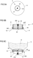
- Figs. 5A-5C show more details of the already mentioned valve 2 of the drinking bottles 1A-1D according to Figs. 1A-4 .
- Fig. 5B shows a partially cutaway view from the side and
- Fig. 5C shows a position of use, also in a partially cut-away, side view.
- the valve 2 includes a base 20, which in the example shown is formed in the form of a cross made of webs.
- the base 20 can be firmly connected or connected to the second bottle part 11, for example formed in one piece with it.
- the base 20 is arranged within the bottle opening 13.
- a pin 21 extends away from the interior 110 of the second bottle part 11.
- the pin 21 is fixed at the intersection of the webs of the base 20, for example integrally formed thereon.
- the pin 21 widens starting from the base 20 towards an end 210 facing away from the base 20, in this case continuously in a section adjacent to the end 210.
- the pin 21 is elongated.
- the pin 21 can widen continuously over its entire length.
- the valve 2 further comprises a resilient element in the form of a bellows 23, which is (completely) tightly connected to the edge of the bottle opening 13, so that no drink G can escape between the bellows 23 and the bottle opening 13.
- a closure plate 22 is connected to the bellows (completely circumferential). The connection is tight and all-round.
- the closure plate 22 is designed in the form of a circular disk.
- the closure plate 22 has an opening 220, which in the present case is arranged centrally on the closure plate 22.
- the opening 220 is smaller or at most the same size as the pin 21 in the area of its end 220 (and has approximately the same cross-sectional shape).
- the opening 220 and the pin 21 are coaxially aligned with one another.
- the bellows 23 presses the closure plate 22 resiliently (along the arrows) against the pin 21.
- the edge of the opening 220 of the closure plate 22 is pressed against the pin 21.
- the opening 220 of the closure plate 22 is closed in a liquid-tight manner by the pin 21 of the same size or (slightly) larger at its end 210.
- the valve 2 can be moved into an open position by moving the closure plate 22 against the spring force of the bellows 23 (generally the resilient element) in the direction of the base 20 (with arrows in Fig. 5C indicated). This can be done, for example, by placing the drinking bottle 1A-1D against the user's mouth, which can be done with just one hand.
- folds of the bellows 23 are pressed closer together. If there is no external force on the closure plate 22, it is automatically moved from the open position to the closed position by the bellows 23. The folds of the bellows 23 widen.
- Fig. 5C shows valve 2 in the open position. Since the pin 21 has a smaller diameter in the direction of the base 20 than at its end 210, the pin no longer completely closes the opening of the closure plate 22. Drink G can now be dispensed through the partially opened opening 220.
- an outer ring 24 is provided, which surrounds the bellows 23 on the outside.
- a thread 240 or the like for the cover 15 is also provided on the outer ring 24.
- the outer ring 24 is projected beyond the pin 21 along the longitudinal direction of the pin 21 in the direction away from the base 20.
- the outer ring 24 optionally serves as a stop for the closure plate 22 when the closure plate 22 is moved from the closed position to the open position.
- valve 2 is additionally provided with a hose 25.
- the hose 25 accommodates the pin 21.
- the hose 25 extends from the base 20 through the opening 220 of the closure plate 22 (both in the closed position and in the open position.
- the hose 25 is flexible (eg made of silicone or the like). In the closed position (see in particular Fig. 6B ), the closure plate 22 compresses the hose 25 and presses it against the pin 21. The hose seals the closure plate 22 against the pin 21.
- the closure plate 22 does not press the hose 25 against the pin 21.
- the free end of the hose 25 is therefore not compressed and is expanded due to the elasticity of the hose 25 (compared to the closed position). This creates a distance between the pin 21 and the hose 25 through which the drink G can be dispensed.
- the hose 25 is a drinking hose.
- the base 20 is closed outside the hose 25 to make cleaning the drinking bottle easier.
Landscapes
- Engineering & Computer Science (AREA)
- Mechanical Engineering (AREA)
- General Engineering & Computer Science (AREA)
- Physics & Mathematics (AREA)
- Fluid Mechanics (AREA)
- Closures For Containers (AREA)
- Table Devices Or Equipment (AREA)
Description
- Trinkflaschen weisen üblicherweise einen Flaschenkörper mit einem Innenraum zur Aufnahme eines Getränks auf, das z.B. durch einen Trinkstutzen hindurch abgegeben werden kann. Insbesondere unterwegs und im sportlichen Bereich ist es üblich, den Trinkstutzen direkt an den Mund anzusetzen, um aus der Flasche zu trinken. Dabei hebt die trinkende Person einen Boden der Trinkflasche so weit an, dass das Getränk durch den Trinkstutzen fließen kann. Hierbei neigt die trinkende Person den Kopf in den Nacken. Je weiter das Getränk in der Trinkflasche zur Neige geht, desto steiler muss der Winkel sein, in den die Flasche anzuheben ist, was zu einer Trinkhaltung mit einem immer weiter nach hinten geneigten Kopf führt. Eine solche Trinkhaltung ist nicht nur unkomfortabel, denn je weiter der Kopf nach hinten geneigt ist, desto unangenehmer wird es zu schlucken. Eine derartige Trinkhaltung kann überdies auch Gefahren bergen, etwa wenn ein während der Fahrt trinkender Fahrradfahrer die Straße nur noch aus dem Augenwinkel sehen kann.
-
KR 1998-0025702 U -
EP 0 891 762 A2 beschreibt eine Halterung mit mehreren relativ zueinander bewegbaren Komponenten, wobei in die Halterung eine Trinkflasche einsetzbar ist. - Die
US 2015/0144584 A1 beschreibt eine Fütterflaschenvorrichtung, mit einer aus zwei zueinander beweglichen Teilen bestehenden Halterung für einen elastischen Flaschenbeutel. - In der
DE 20 2013 011 600 U1 ist ein portabler Mischbehälter mit zum Mischen von Getränkekomponenten verdreh- und/oder verschiebbaren Behälterteilen beschrieben. - Es besteht die Aufgabe, eine Trinkflasche bereitzustellen, die einem Benutzer eine besonders komfortable Trinkhaltung erlaubt.
- Diese Aufgabe wird durch eine Trinkflasche mit den Merkmalen des Anspruchs 1 gelöst.
- Danach umfasst die Trinkflasche ein erstes Flaschenteil und ein zweites Flaschenteil. Beide Flaschenteile umfassen jeweils einen Innenraum, wobei der Innenraum zur Aufnahme und Aufbewahrung einer Flüssigkeit, nämlich eines Getränks, ausgebildet ist. Das zweite Flaschenteil umfasst ferner eine Flaschenöffnung. Die Flaschenöffnung ist zur Abgabe des Getränks an einen Benutzer der Trinkflasche ausgebildet. Die Flaschenöffnung ist oder umfasst z.B. eine Trinköffnung, insbesondere ein Trinkstutzen. Dabei ist vorgesehen, dass die Innenräume der beiden Flaschenteile miteinander in Fluidverbindung stehen oder bringbar sind. Das Getränk kann so von einem der beiden Flaschenteile in den anderen der beiden Falschenteile fließen und umgekehrt. Dabei ist vorgesehen, dass die Trinkflasche zumindest eine Konfiguration aufweist, in der die beiden Flaschenteile schräg und/oder angewinkelt zueinander verlaufen und/oder ausgerichtet sind. Hierbei kann insbesondere eine Symmetrieachse des ersten Flaschenteils schräg zu einer Symmetrieachse des zweiten Flaschenteils ausgerichtet sein. Beispielsweise ist die Flaschenöffnung koaxial zur Symmetrieachse des zweiten Flaschenteils angeordnet. Ferner ist vorgesehen, dass die beiden Flaschenteile relativ zueinander um eine Rotationsachse drehbar sind.
- Durch die schräge Ausrichtung der Flaschenteile zueinander ist eine besonders komfortable Trinkhaltung möglich, denn während das zweite Flaschenteil mit der Flaschenöffnung in einem angenehm flachen Winkel an den Mund gehalten wird, kann das erste Flaschenteil in einem steileren Winkel aufrecht gehalten werden, sodass das Getränk zügig abgegeben werden kann.
- Die beiden Flaschenteile können separate Materialstücke sein oder alternativ auch einstückig miteinander ausgebildet sein.
- Die Trinkflasche weist eine aufrechte Konfiguration auf, in der die beiden Flaschenteile aufrecht angeordnet sind, insbesondere nicht schräg zueinander ausgerichtet sind. Es ist vorgesehen, dass die beiden Flaschenteile in beiden Konfigurationen (der schrägen und der aufrechten) in Fluidverbindung miteinander stehen, und es kann insbesondere vorgesehen sein, dass die beiden Flaschenteile stets miteinander in Fluidverbindung stehen.
- Die Trinkflasche umfasst die Dreh- oder Schwenkverbindung zwischen den Flaschenteilen, durch die die beiden Flaschenteile relativ zueinander um die Rotationsachse dreh- oder schwenkbar sind. Dabei ist vorgesehen, dass die Rotationsachse schräg zu zumindest einem der beiden Flaschenteile ausgerichtet ist, optional zu beiden Flaschenteilen. Optional umfasst das erste Flaschenteil ein Verbindungsstück und das zweite Flaschenteil umfasst ein Verbindungsstück. Dabei können die Innenräume der Flaschenteile über die Verbindungsstücke miteinander in Fluidverbindung stehen oder bringbar sein. Durch die Verbindungsstücke können die beiden Flaschenteile aneinander befestigt sein.
- Durch die schräge Ausrichtung der Rotationsachse kann die Trinkflasche von einer aufgerichteten Konfiguration in eine angewinkelte Konfiguration verdreht werden. In der aufrechten Konfiguration sind die beiden Flaschenteile z.B. (insbesondere koaxial) zueinander ausgerichtet. Dies ermöglicht einen Transport und/oder eine Aufbewahrung der Trinkflasche in gewohnter Weise. In der angewinkelten Konfiguration erstrecken sich die beiden Flaschenteile in einem Winkel (größer 0 Grad und kleiner 180 Grad) zueinander. In der angewinkelten Konfiguration ist eine besonders komfortable Trinkhaltung möglich.
- Die Trinkflasche ist durch Verdrehen der beiden Flaschenteile zueinander um 180 Grad um die Rotationsachse von der aufgerichteten Konfiguration in die angewinkelte Konfiguration überführbar.
- Der Innenraum des ersten Flaschenteils und der Innenraum des zweiten Flaschenteils bilden gemeinsam das Volumen der Trinkflasche. Die Innenräume der beiden Flaschenteile können unterschiedlich groß oder (im Wesentlichen) gleich groß sein. Beispielsweise trägt jeder der Innenräume beider Flaschenteile jeweils zumindest 10%, zumindest 20% oder zumindest 30% zum Fassungsvermögen der Trinkflasche bei.
- Bevorzugt ist zumindest eines der beiden Flaschenteile entlang einer Längsachse längserstreckt. Alternativ oder zusätzlich bildet die Trinkflasche in zumindest einer Konfiguration, insbesondere in der aufgerichteten Konfiguration, die Längsachse aus. Die Rotationsachse verläuft schräg zur Längsachse.
- Der Winkel zwischen der Rotationsachse und der Längsachse beträgt z.B. zwischen 20 und 60 Grad, insbesondere zwischen 30 und 40 Grad. Hierdurch sind angewinkelte Konfigurationen mit besonders komfortabler Trinkhaltung möglich.
- Das erste Flaschenteil umfasst einen Boden, wobei der kleinste Abstand zwischen dem Boden und der Flaschenöffnung durch Verdrehen der beiden Flaschenteile relativ zueinander veränderbar ist. Beispielsweise ist der kleinste Abstand zwischen dem Boden und der Flaschenöffnung in der aufrechten Konfiguration der Trinkflasche maximal und in der angewinkelten Konfiguration der Trinkflasche minimal.
- Zumindest eines der beiden Flaschenteile kann zumindest an einem Abschnitt zylinderförmig ausgebildet sein und eine Zylinderachse aufweisen. Dabei verläuft die Zylinderachse bevorzugt koaxial zur Längsachse und/oder definiert die Längsachse des jeweiligen Flaschenteils. Insbesondere ist hierbei eine kreiszylindrische Form möglich, wobei auch Zylinder mit von einem Kreis abweichenden Querschnittsformen denkbar sind. Die zylindrische Form kann schräg abgeschnitten sein.
- Das erste Flaschenteil kann einen Dachabschnitt umfassen, an dem das Verbindungsstück des ersten Flaschenteils ausgebildet ist. Der Dachabschnitt erstreckt sich z.B. in einer zur Rotationsachse senkrechten Ebene. Das erste Flaschenteil umfasst einen Boden, der insbesondere schräg zum Dachabschnitt verlaufen kann, vorzugsweise im demselben Winkel, der zwischen der Rotationsachse und der Längsachse ausgebildet ist. Der Dachabschnitt liegt dem Boden gegenüber. Der Boden erstrecht sich z.B. in einer zur Längsachse senkrechten Ebene.
- Das zweite Flaschenteil kann einen Bodenabschnitt umfassen, der sich benachbart und parallel zum Dachabschnitt des ersten Flaschenteils erstreckt. Der Bodenabschnitt kann sich am Dachabschnitt abstützen.
- Die Schwenk- oder Drehverbindung kann durch die Verbindungsstücke der beiden Flaschenteile ausgebildet werden. Die Verbindungsstücke können somit sowohl die Fluidverbindung als auch die Schwenk- oder Drehverbindung bereitstellen.
- Die beiden Verbindungsstücke bilden gemeinsam optional eine Schraubverbindung aus. Dies ermöglicht sowohl eine einfache Montage der Trinkflasche als auch eine sichere Drehbarkeit und Halterung.
- Die Flaschenöffnung ist bevorzugt mittels eines Flaschenverschlusses flüssigdicht verschlossen.
- An der Flaschenöffnung ist in einer Ausgestaltung der Trinkflasche ein als Flaschenverschluss dienendes Ventil angeordnet. Das Ventil umfasst z.B. eine mit der Trinkflasche verbundene oder verbindbare Basis, einen von der Basis abstehenden Zapfen, dessen Durchmesser (senkrecht zu einer Längserstreckungsrichtung des Zapfens) sich von der Basis hin zu einem von der Basis abgewandten Ende des Zapfens bis zu einem Enddurchmesser vergrößert, insbesondere zumindest abschnittsweise kontinuierlich. Das Ventil umfasst ferner eine bezüglich des Zapfens bewegbare Verschlussplatte, die eine Öffnung mit einem Öffnungsdurchmesser aufweist. Dabei ist der Öffnungsdurchmesser kleiner oder gleich dem Enddurchmesser des Zapfens. Das Ventil umfasst ferner ein federelastisches Element, welches sich an der Basis oder in der Nähe der Basis abstützt und die Verschlussplatte mit einer Federkraft in eine Verschlussstellung vorspannt, in der die Öffnung durch den Zapfen derart verschlossen ist, dass das Getränk in der Flasche nicht aus dem Ventil austreten kann. Dabei ist vorgesehen, dass die Verschlussplatte aus der Verschlussstellung heraus gegen die Federkraft des federelastischen Elements in eine Öffnungsstellung bewegbar ist, in der die Öffnung der Verschlussplatte zumindest teilweise freigegeben ist. Der freigegebene Öffnungsquerschnitt entspricht dem Querschnitt der Öffnung der Verschlussplatte abzüglich dem Querschnitt des Zapfens an der Stelle der Verschlussplatte.
- Dieses Ventil ermöglicht eine besonders komfortable Abgabe des Getränks aus der Trinkflasche durch Ansetzen des Ventils an den Mund. Insbesondere ist eine einhändige Handhabung möglich, indem die Trinkflasche mit dem Ventil an den Mund angesetzt und zur Abgabe des Getränks lediglich gegen den Mund gedrückt wird. Das Ventil kann als Trinkstutzen dienen.
- Anders als bei üblichen Trinkstutzen ermöglicht dieses Ventil, dass bei einem Drehen der Trinkflasche und beim Halten der Trinkflasche in der gedrehten Position, in der der Boden der Flasche höher liegt als die Flaschenöffnung, kein Getränk aus der Trinkflasche ungewollt austritt.
- Das Ventil umfasst optional einen Außenring, der den Zapfen von außen in einer Umfangsrichtung umgibt, wobei der Zapfen den Außenring in axialer Richtung des Zapfens überragt. Beispielsweise sind der Außenring und der Zapfen koaxial zueinander ausgerichtet. Der Außenring schützt das federelastische Element und kann einen Anschlag für die Öffnungsstellung bereitstellen.
- Optional umfasst das Ventil einen Schlauch, der den Zapfen umgibt, insbesondere aufnimmt, und sich durch die Öffnung der Verschlussplatte hindurch erstreckt. Dieser Schlauch kann als Trinkschlauch dienen und es einem Benutzer erleichtern, aus der Trinkflasche zu trinken. Der Schlauch ist z.B. flexibel. Es kann vorgesehen sein, dass die Verschlussplatte den Schlauch in der Verschlussstellung gegen den Zapfen drückt, sodass die Trinkflasche flüssigkeitsdicht verschlossen ist.
- Ferner wird ein Ventil für eine Trinkflasche beschrieben.
- Ein solches Ventil für eine Trinkflasche, insbesondere für eine Trinkflasche nach einer beliebigen hierin beschriebenen Ausgestaltung, umfasst eine mit der Trinkflasche verbundene oder verbindbare Basis, einen von der Basis abstehenden Zapfen, dessen Durchmesser sich zu einem von der Basis abgewandten Ende des Zapfens hin bis zu einem Enddurchmesser vergrößert (insbesondere zumindest abschnittsweise kontinuierlich), eine bezüglich des Zapfens bewegbare Verschlussplatte, die eine Öffnung mit einem Öffnungsdurchmesser aufweist, der kleiner oder gleich dem Enddurchmesser des Zapfens ist, und ein federelastisches Element, welches sich an der Basis abstützt und die Verschlussplatte mit einer Federkraft in eine Verschlussstellung vorspannt, in der die Öffnung durch den Zapfen verschlossen ist. Dabei ist die Verschlussplatte aus der Verschlussstellung heraus gegen die Federkraft des federelastischen Elements in eine Öffnungsstellung bewegbar, in der die Öffnung der Verschlussplatte zumindest teilweise freigegeben ist.
- Dieses Ventil ermöglicht eine besonders komfortable Abgabe des Getränks aus der Trinkflasche durch Ansetzen des Ventils an den Mund. Insbesondere ist eine einhändige Handhabung möglich, indem die Trinkflasche mit dem Ventil an den Mund angesetzt und zur Abgabe des Getränks lediglich gegen den Mund gedrückt wird.
- Das Ventil kann wie zuvor im Zusammenhang mit der Trinkflasche beschrieben ausgebildet sein.
- Die Erfindung wird nachfolgend unter Bezugnahme auf die Figuren anhand von Ausführungsbeispielen näher erläutert werden. Es zeigen in schematischen Darstellungen:
- Fig. 1A-1C
- verschiedene Ansichten eines Ausführungsbeispiels einer Trinkflasche mit zwei relativ zueinander drehbaren Flaschenteilen mit einer Schraubverbindung;
- Fig. 2A-2B
- verschiedene Ansichten eines Ausführungsbeispiels einer Trinkflasche mit zwei relativ zueinander drehbaren Flaschenteilen mit einem Trichter;
- Fig. 3
- ein Ausführungsbeispiel einer Trinkflasche mit zwei relativ zueinander drehbaren Flaschenteilen mit einer Rastverbindung;
- Fig. 4
- ein Ausführungsbeispiel einer Trinkflasche mit zwei relativ zueinander drehbaren Flaschenteilen mit einer Schraubverbindung, die sich in einen Innenraum eines der Flaschenteile in Richtung einer Flaschenöffnung erstreckt;
- Fig. 5A-5C
- verschiedene Ansichten eines Ventils der Trinkflaschen gemäß
Fig. 1A-4 ; und - Fig. 6A-6C
- verschiedene Ansichten eines Ventils der Trinkflaschen gemäß
Fig. 1A-4 mit einem zusätzlichen Schlauch. -
Fig. 1A zeigt eine aufrecht stehende Trinkflasche 1A mit zwei Flaschenteilen, nämlich einem unteren ersten Flaschenteil 10 und einem oberen zweiten Flaschenteil 11. Die Trinkflasche 1A dient zur Aufbewahrung und Abgabe eines Getränks G an einen Benutzer. - Am ersten Flaschenteil 10 ist ein Boden 102 der Trinkflasche 1A ausgebildet. Am zweiten Flaschenteil 11 ist eine Flaschenöffnung 13 der Trinkflasche 1A ausgebildet. In der in
Fig. 1A gezeigten Konfiguration sind der Boden 102 und die Flaschenöffnung 13 an gegenüberliegenden längsseitigen Enden der Trinkflasche 1A angeordnet. - Das erste Flaschenteil 10 umfasst eine umlaufende Wandung 103. Gemeinsam mit dem Boden 102 und einem dem Boden 102 gegenüberliegenden Dachabschnitt 104 definiert die Wandung 103 einen Innenraum 100. Der Innenraum 100 ist zur Aufnahme einer Flüssigkeit, vorliegend des Getränks G ausgebildet.
- Das zweite Flaschenteil 11 umfasst ebenfalls eine umlaufende Wandung 115. Die Wandung 115 und die Flaschenöffnung 13 definieren gemeinsam mit einem der Flaschenöffnung 13 gegenüberliegenden Bodenabschnitt 112 einen weitere Innenraum 110. Die Flaschenöffnung 13 ist durch ein Ventil 2 verschlossen. Das Ventil 2 dient als Trinkstutzen und kann durch den Benutzer der Trinkflasche 1A geöffnet werden. Das Ventil 2 ist durch einen das Ventil 2 überdeckenden Deckel 15 geschützt.
- Die Wandungen 103, 115 der beiden Flaschenteile 10, 11 sind im Wesentlichen zylinderförmig, vorliegend kreiszylinderförmig, wobei auch andere Formen denkbar sind. In der in
Fig. 1A gezeigten Konfiguration verlaufen die Zylinderachsen der beiden Flaschenteile 10, 11 koaxial zueinander. - Jedes der beiden Flaschenteile 10, 11 umfasst ein Verbindungsstück 101A, 111A, vorliegend jeweils mit einem Gewinde. Das Gewinde des Verbindungsstücks 101A des ersten Flaschenteils 10 steht mit dem Gewinde des Verbindungsstücks 111A des zweiten Flaschenteils 11 in Eingriff. Beide Verbindungsstücke 101A, 111A sind in Form einer Buchse ausgebildet, wobei eines der beiden Verbindungsstücke 101A, 111A (vorliegend das des zweiten Flaschenteils 11) von dem anderen Verbindungsstück 101A, 111A aufgenommen ist.
- Durch die Verbindungsstücke 101A, 111A hindurch stehen die beiden Innenräume 100, 110 der Flaschenteile 10, 11 miteinander in Fluidverbindung, sodass bei jeweils entsprechender Neigung der Trinkflasche 1A das Getränk G von dem ersten in den zweiten Flaschenteil 10, 11 fließen kann und umgekehrt. Eine zwischen den Verbindungsstücken 101A, 111A (umlaufend) angeordnete Dichtung 14 verhindert ein ungewolltes Austreten des Getränks an den Verbindungsabschnitten 101A, 111A.
- Hält der Benutzer die Trinkflasche 1A so, dass der Boden 102 deutlich höher liegt als die Flaschenöffnung 13, so kann bei geöffnetem Ventil 2 das Getränk aus der Trinkflasche 1A abgegeben werden. In der in
Fig. 1A gezeigten Konfiguration kann das zu einer unbequemen Trinkhaltung mit weit in den Nacken geworfenem Kopf führen, insbesondere wenn das Getränk G zur Neige geht. - Daher weist die Trinkflasche 1A eine Schwenkverbindung S auf. Die Schwenkverbindung S wird vorliegend gebildet durch die beiden Verbindungsstücke 101A, 111A der Flaschenteile 10, 11, konkret durch deren miteinander in Eingriff stehenden Gewinde. Mittels der Schwenkverbindung S sind die beiden Flaschenteile 10, 11 relativ zueinander drehbar. Die Drehung erfolgt bezüglich einer Rotationsachse R, die durch die Anordnung der Verbindungsabschnitte 101A, 111A definiert wird.
- Die Rotationsachse R verläuft schräg zu beiden Flaschenteilen 10, 11. Hierdurch kann die Trinkflasche 1A in eine von ihrer in
Fig. 1A gezeigten aufgerichteten Konfiguration in eine angewinkelte Konfiguration verschwenkt werden, wie weiter unten erläutert werden wird. - Die Verbindungsabschnitte 101A, 111A sind jeweils am Dachabschnitt 104 bzw. am Bodenabschnitt 112 der beiden Flaschenteile 10, 11 ausgebildet, im vorliegenden Beispiel jeweils mittig am Dachabschnitt 104 bzw. am Bodenabschnitt 112. Der Dachabschnitt 104 und der Bodenabschnitt 112 verlaufen in etwa parallel zueinander. Konkret sind sowohl der Dachabschnitt 104 als auch der Bodenabschnitt 112 im Wesentlichen eben.
- Die Verbindungsabschnitte 101A, 111A erstrecken sich jeweils in einer Richtung senkrecht zur Ebene des Dachabschnitts 104 bzw. des Bodenabschnitts 112, stehen insbesondere senkrecht dazu davon ab.
- Der Dachabschnitt 104 und der Bodenabschnitt 112 sind jeweils schräg am ersten bzw. zweiten Flaschenteil 10, 11 angeordnet. Der Bodenabschnitt 112 erstreckt sich in einer Ebene, die schräg (z.B. in einem Winkel von 25 bis 35 Grad, insbesondere etwa 30 Grad) zur Zylinderachse des ersten Flaschenteils 10 verläuft. Der Dachabschnitt 104 erstreckt sich in einer Ebene, die schräg zur Zylinderachse des zweiten Flaschenteils 11 verläuft (insbesondere im selben Winkel wie der Dachabschnitt 104 zur Zylinderachse des ersten Flaschenteils 10).
- Die Rotationsachse R verläuft senkrecht zum Dachabschnitt 104 und zum Bodenabschnitt 112. Somit verläuft die Rotationsachse R schräg zur Zylinderachse des ersten und des zweiten Flaschenteils 10, 11. Vorliegend verläuft die Rotationsachse R schräg zu einer Längsachse L des ersten Flaschenteils 10. Die Längsachse L erstreckt sich längs entlang der Längserstreckungsrichtung des ersten Flaschenteils 10 (und/oder koaxial zu dessen Zylinderachse).
-
Fig. 1B zeigt die angewinkelte Konfiguration der Trinkflasche 1A. Gegenüber der inFig. 1A gezeigten aufgerichteten Konfiguration sind die beiden Flaschenteile 10, 11 um 180 Grad zueinander verschwenkt. Durch den schrägen Verlauf der Rotationsachse R stehen die Zylinderachsen der beiden Flaschenteile 10, 11 in einem Winkel zueinander. Hält der Benutzer die Trinkflasche 1A in dieser angewinkelten Konfiguration an den Mund, ist eine wesentlich komfortablere Trinkhaltung möglich, bei der der Kopf vergleichsweise aufrecht gehalten werden kann. Hierbei hält der Benutzer das erste Flaschenteil 10 in einem steileren Winkel zur Waagrechten als das zweite Flaschenteil 11. - Die Trinkflasche 1A weist somit eine aufgerichtete Konfiguration und eine angewinkelte Konfiguration auf. In der angewinkelten Konfiguration ist der Abstand zwischen dem Boden 102 und der Flaschenöffnung 13 kleiner als in der aufgerichteten Konfiguration.
-
Fig. 1C zeigt die beiden Flaschenteile 10, 11 in einem auseinandergeschraubten Zustand. Hier ist zu erkennen, dass das Gewinde 105 des ersten Flaschenteils als Außengewinde ausgebildet ist und das Gewinde 113 des zweiten Flaschenteils 11 als Innengewinde. Ferner zeigtFig. 1C einen Anschlag 106, der am Verbindungsstück 101A des ersten Flaschenteils 10 vorgesehen ist und der mit einem Gegenanschlag 114 (oder mehreren in Drehrichtung versetzt zueinander angeordneten Gegenanschlägen) am Verbindungsstück 111A des zweiten Flaschenteils 11 kooperiert. Der Anschlag 106 und der Gegenanschlag 114 begrenzen den maximalen Drehwinkel der Flaschenteile zueinander auf 180 Grad. - Auf diese Weise wird ein versehentliches Lösen der Flaschenteile 10, 11 voneinander vermieden.
- Zumindest eines der beiden Flaschenteile 10, 11 ist einstückig ausgebildet. Vorzugsweise sind beide Flaschenteile 10, 11 jeweils einstückig ausgebildet.
- Die
Fig. 2A und2B zeigen eine Trinkflasche 1B, die ähnlich der Trinkflasche gemäßFig. 1A-1C ausgebildet ist. Die Trinkflasche 1B gemäßFig. 2A (aufgerichtete Konfiguration) und 2B (angewinkelte Konfiguration) umfasst zusätzlich eine Innenwand 107, welche verhindert, dass ein Teil des Getränks G bei der Abgabe in der angewinkelten Konfiguration (sieheFig. 2B ) im ersten Flaschenteil 10 zurückbleibt. Die Innenwand 107 ist vorliegend trichterförmig ausgebildet. - Gemäß
Fig. 2A und2B erstecken sich die Verbindungsstücke 101A, 111A vom Dachabschnitt 104 bzw. Bodenabschnitt 112 ausgehend in den Innenraum 100 des ersten Flaschenteils 10. Die Innenwand 107 ist an einem dem Dachabschnitt 104 abgewandten Ende des Verbindungsstücks 101A des ersten Flaschenteils fest verbunden und erstreckt sich von dort umlaufend bis zur Wandung 103 des ersten Flaschenteils 10. -
Fig. 3 zeigt eine weitere Trinkflasche 1C, die ähnlich der Trinkflasche gemäßFig. 1A-1C ausgebildet ist. Verglichen damit umfasst sie aber anders ausgebildete Verbindungsstücke 101B, 111B. Die Verbindungsstücke 101B, 111B des ersten und zweiten Flaschenteils 10, 11 gemäßFig. 3 sind in Form einer Rastverbindung ausgebildet. Zur Montage werden die beiden Verbindungsstücke 101B, 111B miteinander verrastet. Dies ermöglicht eine einfache und zugleich sichere Verbindung. Innerhalb der Verbindungsstücke 101B, 111B ist wie bei den Verbindungsstücken 101A, 111A gemäßFig. 1A-2B eine Öffnung ausgebildet, durch die hindurch die Innenräume 100, 110 der Flaschenteile 10, 11 miteinander verbunden sind. Der Durchmesser der Öffnung der Trinkflasche 1C gemäßFig. 3 beträgt in einer Richtung mehr als 80 %, insbesondere mehr als 90 % des Durchmessers des ersten Flaschenteils 10 und/oder des zweiten Flaschenteils 11. Eine entsprechend groß dimensionierte Öffnung ist auch bei den Trinkflaschen 1A-1B gemäßFig. 1A-2B möglich. -
Fig. 4 zeigt eine weitere Trinkflasche 10, die ähnlich der Trinkflasche gemäßFig. 1A-1C ausgebildet ist. Als einziger Unterschied erstrecken sich die Verbindungsstücke 101C, 111C der Trinkflasche 1D gemäßFig. 4 ausgehend vom Dachabschnitt 104 und vom Bodenabschnitt 102 in den Innenraum des zweiten Flaschenteils 11. Hierdurch kann weitgehend vermieden werden, dass in der angewinkelten Konfiguration Teile des Getränks G durch die Verbindungsstücke 101C, 111C im ersten Flaschenteil 10 zurückbehalten werden. -
Fig. 5A-5C zeigen mehr Details des bereits erwähnten Ventils 2 der Trinkflaschen 1A-1D gemäßFig. 1A-4 . Dabei zeigtFig. 5A eine Draufsicht von oben auf das Ventil und das zweite Flaschenteil 11 der Trinkflasche 1A-1D.Fig. 5B zeigt eine teilweise aufgeschnittene Ansicht von der Seite undFig. 5C zeigt eine Gebrauchsposition, ebenfalls in einer teilweise aufgeschnittenen, seitlichen Ansicht. - Das Ventil 2 umfasst eine Basis 20, welche im gezeigten Beispiel in Form eines Kreuzes aus Stegen gebildet ist. Die Basis 20 ist fest mit dem zweiten Flaschenteil 11 verbindbar oder verbunden, z.B. einstückig damit ausgebildet. Die Basis 20 ist innerhalb der Flaschenöffnung 13 angeordnet.
- Von der Basis 20 ausgehend erstreckt sich ein Zapfen 21 weg vom Innenraum 110 des zweiten Flaschenteils 11. Der Zapfen 21 ist vorliegend am Kreuzungspunkt der Stege der Basis 20 festgelegt, z.B. einstückig daran angeformt. Der Zapfen 21 verbreitert sich ausgehend von der Basis 20 hin zu einem der Basis 20 abgewandten Ende 210, vorliegend kontinuierlich in einem an das Ende 210 angrenzenden Abschnitt. Der Zapfen 21 ist länglich. Optional kann sich der Zapfen 21 über seine gesamte Länge kontinuierlich verbreitern.
- Das Ventil 2 umfasst ferner ein federelastisches Element in Form eines Balges 23, der (vollständig) umlaufend mit dem Rand der Flaschenöffnung 13 dicht verbunden ist, sodass zwischen Balg 23 und Flaschenöffnung 13 kein Getränk G austreten kann. An einem der Basis 20 abgewandten Ende des Balges ist eine Verschlussplatte 22 mit dem Balg (vollständig umlaufend) verbunden. Die Verbindung ist dicht und umlaufend. Die Verschlussplatte 22 ist im vorliegenden Beispiel in Form einer Kreisscheibe ausgebildet. Die Verschlussplatte 22 weist eine Öffnung 220 auf, die vorliegend mittig an der Verschlussplatte 22 angeordnet ist. Die Öffnung 220 ist kleiner oder höchstens gleichgroß wie der Zapfen 21 im Bereich seines Endes 220 (und weist in etwa dieselbe Querschnittsform auf). Die Öffnung 220 und der Zapfen 21 sind koaxial zueinander ausgerichtet.
- Wie in
Fig. 5B gezeigt, drückt der Balg 23 die Verschlussplatte 22 federelastisch (entlang der Pfeile) gegen den Zapfen 21. Dabei wird der Rand der Öffnung 220 der Verschlussplatte 22 gegen den Zapfen 21 gepresst. Die Öffnung 220 der Verschlussplatte 22 wird dabei durch den gleichgroßen oder (geringfügig) größeren Zapfen 21 an seinem Ende 210 flüssigkeitsdicht verschlossen. - Aus der in
Fig. 5B gezeigten Verschlussstellung kann das Ventil 2 in eine Öffnungsstellung überführt werden, indem die Verschlussplatte 22 gegen die Federkraft des Balges 23 (allgemein des federelastischen Elements) in Richtung der Basis 20 bewegt wird (mit Pfeilen inFig. 5C angedeutet). Dies kann z.B. durch Ansetzen der Trinkflasche 1A-1D an den Mund des Benutzers erfolgen, was insbesondere bereits einhändig möglich ist. Hierbei werden Faltungen des Balges 23 enger zusammen gedrückt. Entfällt eine äußere Krafteinwirkung auf die Verschlussplatte 22, wird diese durch den Balg 23 automatisch von der Öffnungsstellung in die Verschlussstellung bewegt. Die Faltungen des Balges 23 weiten sich dabei. - Hierdurch wird verhindert, dass beim Drehen und Halten der Trinkflasche 1A-1D mit der Flaschenöffnung 13 nach unten Getränk G ungewollt austritt. Erst durch Ansetzen des Ventils 2 an den Mund wird Getränk G abgegeben.
-
Fig. 5C zeigt das Ventil 2 in der Öffnungsstellung. Da der Zapfen 21 in Richtung zur Basis 20 einen geringeren Durchmesser aufweist als an seinem Ende 210, verschließt der Zapfen die Öffnung der Verschlussplatte 22 nicht mehr vollständig. Durch die teilweise freigegebene Öffnung 220 kann nun Getränk G abgegeben werden. - Zum Schutz von Teilen des Ventils 2 ist ein Außenring 24 vorgesehen, der den Balg 23 außen umgibt. Am Außenring 24 ist ferner ein Gewinde 240 oder dergleichen für den Deckel 15 vorgesehen. Der Außenring 24 wird entlang der Längsrichtung des Zapfens 21 in Richtung weg von der Basis 20 vom Zapfen 21 überragt. Der Außenring 24 dient optional als Anschlag für die Verschlussplatte 22, wenn die Verschlussplatte 22 von der Verschlussstellung in die Öffnungsstellung bewegt wird.
- Gemäß
Fig. 6A-6C ist das Ventil 2 zusätzlich mit einem Schlauch 25 versehen. Der Schlauch 25 nimmt den Zapfen 21 in sich auf. Der Schlauch 25 erstreckt sich von der Basis 20 durch die Öffnung 220 der Verschlussplatte 22 hindurch (sowohl in der Verschlussstellung als auch in der Öffnungsstellung. - Der Schlauch 25 ist flexibel (z.B. aus Silikon oder dergleichen hergestellt). In der Verschlussstellung (siehe insbesondere
Fig. 6B ) komprimiert die Verschlussplatte 22 den Schlauch 25 und drückt ihn gegen den Zapfen 21. Der Schlauch dichtet die Verschlussplatte 22 gegenüber dem Zapfen 21 ab. - In der Öffnungsstellung (siehe insbesondere
Fig. 6C ) drückt die Verschlussplatte 22 den Schlauch 25 nicht gegen den Zapfen 21. Das freie Ende des Schlauchs 25 wird somit nicht komprimiert und ist infolge der Elastizität des Schlauchs 25 (gegenüber der Verschlussstellung) geweitet. So entsteht ein Abstand zwischen dem Zapfen 21 und dem Schlauch 25, durch den hindurch das Getränk G abgegeben werden kann. Der Schlauch 25 ist ein Trinkschlauch. - Optional ist die Basis 20 außerhalb des Schlauchs 25 verschlossen, um eine Reinigung der Trinkflasche zu erleichtern.
-
- 1A-1D
- Trinkflasche
- 10
- erstes Flaschenteil
- 100
- Innenraum
- 101A-101C
- Verbindungsstück
- 102
- Boden
- 103
- Wandung
- 104
- Dachabschnitt
- 105
- Gewinde
- 106
- Anschlag
- 107
- Innenwand
- 11
- zweites Flaschenteil
- 110
- Innenraum
- 111A-111C
- Verbindungsstück
- 112
- Bodenabschnitt
- 113
- Gewinde
- 114
- Gegenanschlag
- 115
- Wandung
- 13
- Flaschenöffnung
- 14
- Dichtung
- 15
- Deckel
- 2
- Ventil
- 20
- Basis
- 21
- Zapfen
- 210
- Ende
- 22
- Verschlussplatte
- 220
- Öffnung
- 23
- Balg (federelastisches Element)
- 24
- Außenring
- 25
- Schlauch
- 240
- Gewinde
- S
- Schwenkverbindung
- G
- Getränk
- L
- Längsachse
- R
- Rotationsachse
Claims (11)
- Trinkflasche, umfassend:- ein erstes Flaschenteil (10) mit einem Innenraum (100) zur Aufnahme eines Getränks (G) und- ein zweites Flaschenteil (11) mit einem Innenraum (110) zur Aufnahme des Getränks (G) und mit einer Flaschenöffnung (13) zur Abgabe des Getränks (G) aus dem Innenraum (110),wobei:- die Innenräume (100, 110) der beiden Flaschenteile (10, 11) miteinander in Fluidverbindung stehen oder bringbar sind und wobei die Trinkflasche (1A-1D) zumindest eine Konfiguration aufweist, in der die beiden Flaschenteile (10, 11) schräg zueinander verlaufen, und eine aufrechte Konfiguration aufweist, wobei die beiden Flaschenteile (10, 11) in beiden Konfigurationen in Fluidverbindung miteinander stehen,- die Trinkflasche (1A-1D) eine Dreh- oder Schwenkverbindung (S) zwischen den Flaschenteilen (10, 11) umfasst, durch die die beiden Flaschenteile (10, 11) relativ zueinander um eine schräg zu zumindest einem der beiden Flaschenteile (10, 11) verlaufende Rotationsachse (R) dreh- oder schwenkbar sind, und- die Trinkflasche durch Verdrehen der beiden Flaschenteile (10, 11) zueinander um 180 Grad um die Rotationsachse (R) von der aufgerichteten Konfiguration in die angewinkelte Konfiguration überführbar ist.
- Trinkflasche nach Anspruch 1, dadurch gekennzeichnet, dass das erste Flaschenteil (10) ein Verbindungsstück (101A-101C) umfasst und das zweite Flaschenteil (11) ein Verbindungsstück (111A-111C) umfasst, wobei die Innenräume (100, 110) über die Verbindungsstücke (101A-101C, 111A-111C) der beiden Flaschenteile (10, 11) miteinander in Fluidverbindung stehen.
- Trinkflasche nach Anspruch 2, dadurch gekennzeichnet, dass die beiden Flaschenteile (10, 11) über die Verbindungsstücke (101A-101C, 111A-111C) aneinander befestigt sind.
- Trinkflasche nach einem der vorhergehenden Ansprüche, dadurch gekennzeichnet, dass die Rotationsachse (R) schräg zu einer Längsachse (L) zumindest eines der beiden Flaschenteile (10, 11) verläuft.
- Trinkflasche nach Anspruch 5, dadurch gekennzeichnet, dass der Winkel zwischen der Rotationsachse (R) und der Längsachse (L) zwischen 20 und 60 Grad beträgt, insbesondere zwischen 30 und 40 Grad.
- Trinkflasche nach einem der vorhergehenden Ansprüche, dadurch gekennzeichnet, dass das erste Flaschenteil (10) einen Boden (102) umfasst, wobei der kleinste Abstand zwischen dem Boden (102) und der Flaschenöffnung (13) veränderbar ist durch Schwenken der Flaschenteile (10, 11) relativ zueinander.
- Trinkflasche nach einem der vorhergehenden Ansprüche, dadurch gekennzeichnet, dass zumindest eines der beiden Flaschenteile (10, 11) zumindest abschnittsweise zylinderförmig mit einer Zylinderachse ausgebildet ist, wobei die Zylinderachse koaxial zu einer Längsachse (L) zumindest eines der beiden Flaschenteile (10, 11) verläuft.
- Trinkflasche nach einem der vorangehenden Ansprüche, soweit rückbezogen auf Anspruch 3, dadurch gekennzeichnet, dass das erste Flaschenteil (10) einen Dachabschnitt (104) umfasst, an dem das Verbindungsstück (101A-101C) des ersten Flaschenteils (10) ausgebildet ist und der schräg zu einem Boden (102) des ersten Flaschenteils (10) verläuft.
- Trinkflasche nach Anspruch 8, dadurch gekennzeichnet, dass das zweite Flaschenteil (11) einen Bodenabschnitt (112) umfasst, der sich benachbart und parallel zum Dachabschnitt (104) des ersten Flaschenteils (10) erstreckt.
- Trinkflasche nach einem der vorhergehenden Ansprüche, soweit rückbezogen auf Anspruch 3, dadurch gekennzeichnet, dass die Verbindungsstücke (101A-101C, 111A-111C) der beiden Flaschenteile (10, 11) gemeinsam die Schwenkverbindung (S) ausbilden.
- Trinkflasche nach einem der vorangehenden Ansprüche, soweit rückbezogen auf Anspruch 3, dadurch gekennzeichnet, dass die beiden Verbindungsstücke (101A-101C, 111A-111C) eine Schraubverbindung ausbilden.
Priority Applications (1)
| Application Number | Priority Date | Filing Date | Title |
|---|---|---|---|
| EP24166240.2A EP4378853A3 (de) | 2017-08-10 | 2018-08-09 | Trinkflasche |
Applications Claiming Priority (2)
| Application Number | Priority Date | Filing Date | Title |
|---|---|---|---|
| DE102017213976.5A DE102017213976A1 (de) | 2017-08-10 | 2017-08-10 | Trinkflasche |
| PCT/EP2018/071645 WO2019030333A1 (de) | 2017-08-10 | 2018-08-09 | Trinkflasche und ventil dafür |
Related Child Applications (1)
| Application Number | Title | Priority Date | Filing Date |
|---|---|---|---|
| EP24166240.2A Division EP4378853A3 (de) | 2017-08-10 | 2018-08-09 | Trinkflasche |
Publications (3)
| Publication Number | Publication Date |
|---|---|
| EP3665094A1 EP3665094A1 (de) | 2020-06-17 |
| EP3665094B1 true EP3665094B1 (de) | 2024-03-27 |
| EP3665094C0 EP3665094C0 (de) | 2024-03-27 |
Family
ID=63259498
Family Applications (2)
| Application Number | Title | Priority Date | Filing Date |
|---|---|---|---|
| EP18756393.7A Active EP3665094B1 (de) | 2017-08-10 | 2018-08-09 | Trinkflasche |
| EP24166240.2A Withdrawn EP4378853A3 (de) | 2017-08-10 | 2018-08-09 | Trinkflasche |
Family Applications After (1)
| Application Number | Title | Priority Date | Filing Date |
|---|---|---|---|
| EP24166240.2A Withdrawn EP4378853A3 (de) | 2017-08-10 | 2018-08-09 | Trinkflasche |
Country Status (5)
| Country | Link |
|---|---|
| US (1) | US11208234B2 (de) |
| EP (2) | EP3665094B1 (de) |
| CN (1) | CN111201185A (de) |
| DE (1) | DE102017213976A1 (de) |
| WO (1) | WO2019030333A1 (de) |
Families Citing this family (2)
| Publication number | Priority date | Publication date | Assignee | Title |
|---|---|---|---|---|
| USD1015069S1 (en) * | 2021-11-24 | 2024-02-20 | KFS Marketing, Inc. | Drinking bottle |
| USD1007965S1 (en) * | 2022-04-27 | 2023-12-19 | Johnnie Yip | Beverage bottle |
Citations (1)
| Publication number | Priority date | Publication date | Assignee | Title |
|---|---|---|---|---|
| DE202013011600U1 (de) * | 2013-12-27 | 2014-02-25 | Alexander Neumann | Portabler Mischbehälter mit zum Mischen von Getränkekomponenten verdreh- und/oder verschiebbaren Behälterteilen |
Family Cites Families (15)
| Publication number | Priority date | Publication date | Assignee | Title |
|---|---|---|---|---|
| US4099651A (en) * | 1975-05-22 | 1978-07-11 | Von Winckelmann Emil H | Closure assembly for collapsible tube dispensers, and the like |
| CA1191491A (en) * | 1984-03-09 | 1985-08-06 | Hans R. Petkau | Liquid dispensing mechanism |
| US4813556A (en) * | 1986-07-11 | 1989-03-21 | Globestar Incorporated | Collapsible baby bottle with integral gripping elements and liner |
| US5265777A (en) * | 1992-05-18 | 1993-11-30 | Primary Delivery Systems, Inc. | Push-push tilting dispensing cap system |
| KR19980025702U (ko) | 1996-11-05 | 1998-08-05 | 장세준 | 내용물 배출이 용이한 페트병 |
| CN1222342A (zh) | 1997-07-17 | 1999-07-14 | 庄臣消费者有限公司 | 用于一次性使用的喂哺系统的支持器 |
| US6092681A (en) | 1997-07-17 | 2000-07-25 | Johnson & Johnson Consumer Products, Inc. | Holder for use in disposable feeding systems |
| US6814229B2 (en) * | 2002-05-03 | 2004-11-09 | Belle Bottles Llc | Bottle adapter and associated methods |
| KR20090003800U (ko) | 2007-10-19 | 2009-04-23 | 서지연 | 분리가능한 구조를 갖는 휴대용 물병 |
| CN201614046U (zh) | 2010-02-26 | 2010-10-27 | 许玉龙 | 易洗型分体组合瓶 |
| TWM416414U (en) | 2010-11-29 | 2011-11-21 | Sienna Group Corp | Kettle structure |
| WO2015081044A1 (en) | 2013-11-26 | 2015-06-04 | Eveready Battery Company, Inc. | Bottle feeding device |
| CN203793848U (zh) | 2014-03-13 | 2014-08-27 | 山西惠丰机械工业有限公司 | 一种双头螺纹连接聚乙烯塑料两体包装盒 |
| CN106608447B (zh) | 2015-10-21 | 2020-10-27 | 强生消费者公司 | 螺旋瓶 |
| CN205366353U (zh) | 2016-03-06 | 2016-07-06 | 杭州韩创文化创意有限公司 | 一种可拆卸的便携式水瓶 |
-
2017
- 2017-08-10 DE DE102017213976.5A patent/DE102017213976A1/de active Pending
-
2018
- 2018-08-09 EP EP18756393.7A patent/EP3665094B1/de active Active
- 2018-08-09 US US16/637,682 patent/US11208234B2/en active Active
- 2018-08-09 WO PCT/EP2018/071645 patent/WO2019030333A1/de not_active Ceased
- 2018-08-09 EP EP24166240.2A patent/EP4378853A3/de not_active Withdrawn
- 2018-08-09 CN CN201880065551.2A patent/CN111201185A/zh not_active Withdrawn
Patent Citations (1)
| Publication number | Priority date | Publication date | Assignee | Title |
|---|---|---|---|---|
| DE202013011600U1 (de) * | 2013-12-27 | 2014-02-25 | Alexander Neumann | Portabler Mischbehälter mit zum Mischen von Getränkekomponenten verdreh- und/oder verschiebbaren Behälterteilen |
Also Published As
| Publication number | Publication date |
|---|---|
| US11208234B2 (en) | 2021-12-28 |
| DE102017213976A1 (de) | 2018-10-18 |
| WO2019030333A1 (de) | 2019-02-14 |
| CN111201185A (zh) | 2020-05-26 |
| EP3665094A1 (de) | 2020-06-17 |
| US20200198833A1 (en) | 2020-06-25 |
| EP4378853A2 (de) | 2024-06-05 |
| EP4378853A3 (de) | 2024-07-31 |
| EP3665094C0 (de) | 2024-03-27 |
Similar Documents
| Publication | Publication Date | Title |
|---|---|---|
| DE60007147T2 (de) | Tropffreie lösbare ausgiesstülle | |
| DE60104968T2 (de) | Ausgabeventil für Behälter | |
| DE10228559B4 (de) | Strohhalm | |
| DE202010015802U1 (de) | Trinkflaschenverschluß mit Rückstellfunktion | |
| WO2009138183A1 (de) | Push-pull- verschluss für einen trinkbehälter | |
| EP2144705A1 (de) | Dosiervorrichtung | |
| EP3665094B1 (de) | Trinkflasche | |
| EP1254842A1 (de) | Kunststoffbehälter | |
| CH715950A2 (de) | Verschlusskappe zum Verschliessen eines Behälters und Behälter mit einer solchen unverlierbar gehaltenen Verschlusskappe. | |
| DE69902890T2 (de) | Hybridgetränkebehälter | |
| DE102008056301B4 (de) | Vorrichtung zum Öffnen und Verschließen eines Getränkebehälters | |
| WO2020016030A1 (de) | Dosierspender | |
| DE202010015464U1 (de) | Einstellbarer Trinkflaschenverschluß mit Trinkhalmfunktion | |
| DE9302022U1 (de) | Freizeitflasche | |
| EP3087013B1 (de) | Mischbehälter mit zum mischen von produktkomponenten verdreh- und/oder verschiebbaren behälterteilen | |
| EP0955987B1 (de) | Wiederverschliessbare flasche sowie verschlusselement für die flasche | |
| DE102010038080B4 (de) | Trinkbecherdeckel | |
| WO2003024827A1 (de) | Abgabeverschluss für fliessfähiges gut enthaltende behälter | |
| DE102023132792B4 (de) | Verschlusseinheit zur Verbindung mit einer Trinkflasche oder mit einem Becher, insbesondere Thermobecher | |
| DE10042206C2 (de) | Kanne | |
| DE202012104749U1 (de) | Trinkbecherdeckel für ein Trinkgefäß | |
| DE10200079A1 (de) | Kleinbehälter | |
| AT411672B (de) | Flasche mit im boden ausgebildeten griffmulden | |
| DE69809567T2 (de) | Verschlussdeckel für getränkedose mit aussenkappe | |
| CH688858A5 (de) | Faltenbalgfoermige Flasche und Aufnahmebehaeltnis fuer eine solche Flasche. |
Legal Events
| Date | Code | Title | Description |
|---|---|---|---|
| STAA | Information on the status of an ep patent application or granted ep patent |
Free format text: STATUS: UNKNOWN |
|
| STAA | Information on the status of an ep patent application or granted ep patent |
Free format text: STATUS: THE INTERNATIONAL PUBLICATION HAS BEEN MADE |
|
| PUAI | Public reference made under article 153(3) epc to a published international application that has entered the european phase |
Free format text: ORIGINAL CODE: 0009012 |
|
| STAA | Information on the status of an ep patent application or granted ep patent |
Free format text: STATUS: REQUEST FOR EXAMINATION WAS MADE |
|
| 17P | Request for examination filed |
Effective date: 20200310 |
|
| AK | Designated contracting states |
Kind code of ref document: A1 Designated state(s): AL AT BE BG CH CY CZ DE DK EE ES FI FR GB GR HR HU IE IS IT LI LT LU LV MC MK MT NL NO PL PT RO RS SE SI SK SM TR |
|
| AX | Request for extension of the european patent |
Extension state: BA ME |
|
| DAV | Request for validation of the european patent (deleted) | ||
| DAX | Request for extension of the european patent (deleted) | ||
| STAA | Information on the status of an ep patent application or granted ep patent |
Free format text: STATUS: EXAMINATION IS IN PROGRESS |
|
| 17Q | First examination report despatched |
Effective date: 20210924 |
|
| GRAP | Despatch of communication of intention to grant a patent |
Free format text: ORIGINAL CODE: EPIDOSNIGR1 |
|
| STAA | Information on the status of an ep patent application or granted ep patent |
Free format text: STATUS: GRANT OF PATENT IS INTENDED |
|
| INTG | Intention to grant announced |
Effective date: 20231031 |
|
| GRAS | Grant fee paid |
Free format text: ORIGINAL CODE: EPIDOSNIGR3 |
|
| GRAA | (expected) grant |
Free format text: ORIGINAL CODE: 0009210 |
|
| STAA | Information on the status of an ep patent application or granted ep patent |
Free format text: STATUS: THE PATENT HAS BEEN GRANTED |
|
| AK | Designated contracting states |
Kind code of ref document: B1 Designated state(s): AL AT BE BG CH CY CZ DE DK EE ES FI FR GB GR HR HU IE IS IT LI LT LU LV MC MK MT NL NO PL PT RO RS SE SI SK SM TR |
|
| REG | Reference to a national code |
Ref country code: GB Ref legal event code: FG4D Free format text: NOT ENGLISH |
|
| REG | Reference to a national code |
Ref country code: CH Ref legal event code: EP |
|
| REG | Reference to a national code |
Ref country code: DE Ref legal event code: R096 Ref document number: 502018014332 Country of ref document: DE |
|
| REG | Reference to a national code |
Ref country code: IE Ref legal event code: FG4D Free format text: LANGUAGE OF EP DOCUMENT: GERMAN |
|
| U01 | Request for unitary effect filed |
Effective date: 20240426 |
|
| U07 | Unitary effect registered |
Designated state(s): AT BE BG DE DK EE FI FR IT LT LU LV MT NL PT SE SI Effective date: 20240503 |
|
| PG25 | Lapsed in a contracting state [announced via postgrant information from national office to epo] |
Ref country code: GR Free format text: LAPSE BECAUSE OF FAILURE TO SUBMIT A TRANSLATION OF THE DESCRIPTION OR TO PAY THE FEE WITHIN THE PRESCRIBED TIME-LIMIT Effective date: 20240628 |
|
| PG25 | Lapsed in a contracting state [announced via postgrant information from national office to epo] |
Ref country code: HR Free format text: LAPSE BECAUSE OF FAILURE TO SUBMIT A TRANSLATION OF THE DESCRIPTION OR TO PAY THE FEE WITHIN THE PRESCRIBED TIME-LIMIT Effective date: 20240327 Ref country code: RS Free format text: LAPSE BECAUSE OF FAILURE TO SUBMIT A TRANSLATION OF THE DESCRIPTION OR TO PAY THE FEE WITHIN THE PRESCRIBED TIME-LIMIT Effective date: 20240627 |
|
| PG25 | Lapsed in a contracting state [announced via postgrant information from national office to epo] |
Ref country code: RS Free format text: LAPSE BECAUSE OF FAILURE TO SUBMIT A TRANSLATION OF THE DESCRIPTION OR TO PAY THE FEE WITHIN THE PRESCRIBED TIME-LIMIT Effective date: 20240627 Ref country code: NO Free format text: LAPSE BECAUSE OF FAILURE TO SUBMIT A TRANSLATION OF THE DESCRIPTION OR TO PAY THE FEE WITHIN THE PRESCRIBED TIME-LIMIT Effective date: 20240627 Ref country code: HR Free format text: LAPSE BECAUSE OF FAILURE TO SUBMIT A TRANSLATION OF THE DESCRIPTION OR TO PAY THE FEE WITHIN THE PRESCRIBED TIME-LIMIT Effective date: 20240327 Ref country code: GR Free format text: LAPSE BECAUSE OF FAILURE TO SUBMIT A TRANSLATION OF THE DESCRIPTION OR TO PAY THE FEE WITHIN THE PRESCRIBED TIME-LIMIT Effective date: 20240628 |
|
| PG25 | Lapsed in a contracting state [announced via postgrant information from national office to epo] |
Ref country code: IS Free format text: LAPSE BECAUSE OF FAILURE TO SUBMIT A TRANSLATION OF THE DESCRIPTION OR TO PAY THE FEE WITHIN THE PRESCRIBED TIME-LIMIT Effective date: 20240727 |
|
| PG25 | Lapsed in a contracting state [announced via postgrant information from national office to epo] |
Ref country code: SM Free format text: LAPSE BECAUSE OF FAILURE TO SUBMIT A TRANSLATION OF THE DESCRIPTION OR TO PAY THE FEE WITHIN THE PRESCRIBED TIME-LIMIT Effective date: 20240327 |
|
| PG25 | Lapsed in a contracting state [announced via postgrant information from national office to epo] |
Ref country code: ES Free format text: LAPSE BECAUSE OF FAILURE TO SUBMIT A TRANSLATION OF THE DESCRIPTION OR TO PAY THE FEE WITHIN THE PRESCRIBED TIME-LIMIT Effective date: 20240327 |
|
| PG25 | Lapsed in a contracting state [announced via postgrant information from national office to epo] |
Ref country code: CZ Free format text: LAPSE BECAUSE OF FAILURE TO SUBMIT A TRANSLATION OF THE DESCRIPTION OR TO PAY THE FEE WITHIN THE PRESCRIBED TIME-LIMIT Effective date: 20240327 |
|
| PG25 | Lapsed in a contracting state [announced via postgrant information from national office to epo] |
Ref country code: PL Free format text: LAPSE BECAUSE OF FAILURE TO SUBMIT A TRANSLATION OF THE DESCRIPTION OR TO PAY THE FEE WITHIN THE PRESCRIBED TIME-LIMIT Effective date: 20240327 |
|
| PG25 | Lapsed in a contracting state [announced via postgrant information from national office to epo] |
Ref country code: SK Free format text: LAPSE BECAUSE OF FAILURE TO SUBMIT A TRANSLATION OF THE DESCRIPTION OR TO PAY THE FEE WITHIN THE PRESCRIBED TIME-LIMIT Effective date: 20240327 |
|
| PG25 | Lapsed in a contracting state [announced via postgrant information from national office to epo] |
Ref country code: SM Free format text: LAPSE BECAUSE OF FAILURE TO SUBMIT A TRANSLATION OF THE DESCRIPTION OR TO PAY THE FEE WITHIN THE PRESCRIBED TIME-LIMIT Effective date: 20240327 Ref country code: SK Free format text: LAPSE BECAUSE OF FAILURE TO SUBMIT A TRANSLATION OF THE DESCRIPTION OR TO PAY THE FEE WITHIN THE PRESCRIBED TIME-LIMIT Effective date: 20240327 Ref country code: RO Free format text: LAPSE BECAUSE OF FAILURE TO SUBMIT A TRANSLATION OF THE DESCRIPTION OR TO PAY THE FEE WITHIN THE PRESCRIBED TIME-LIMIT Effective date: 20240327 Ref country code: PL Free format text: LAPSE BECAUSE OF FAILURE TO SUBMIT A TRANSLATION OF THE DESCRIPTION OR TO PAY THE FEE WITHIN THE PRESCRIBED TIME-LIMIT Effective date: 20240327 Ref country code: IS Free format text: LAPSE BECAUSE OF FAILURE TO SUBMIT A TRANSLATION OF THE DESCRIPTION OR TO PAY THE FEE WITHIN THE PRESCRIBED TIME-LIMIT Effective date: 20240727 Ref country code: ES Free format text: LAPSE BECAUSE OF FAILURE TO SUBMIT A TRANSLATION OF THE DESCRIPTION OR TO PAY THE FEE WITHIN THE PRESCRIBED TIME-LIMIT Effective date: 20240327 Ref country code: CZ Free format text: LAPSE BECAUSE OF FAILURE TO SUBMIT A TRANSLATION OF THE DESCRIPTION OR TO PAY THE FEE WITHIN THE PRESCRIBED TIME-LIMIT Effective date: 20240327 |
|
| REG | Reference to a national code |
Ref country code: DE Ref legal event code: R097 Ref document number: 502018014332 Country of ref document: DE |
|
| PLBE | No opposition filed within time limit |
Free format text: ORIGINAL CODE: 0009261 |
|
| STAA | Information on the status of an ep patent application or granted ep patent |
Free format text: STATUS: NO OPPOSITION FILED WITHIN TIME LIMIT |
|
| 26N | No opposition filed |
Effective date: 20250103 |
|
| U21 | Renewal fee for the european patent with unitary effect paid with additional fee |
Year of fee payment: 7 Effective date: 20250214 |
|
| PG25 | Lapsed in a contracting state [announced via postgrant information from national office to epo] |
Ref country code: MC Free format text: LAPSE BECAUSE OF FAILURE TO SUBMIT A TRANSLATION OF THE DESCRIPTION OR TO PAY THE FEE WITHIN THE PRESCRIBED TIME-LIMIT Effective date: 20240327 |
|
| PG25 | Lapsed in a contracting state [announced via postgrant information from national office to epo] |
Ref country code: IE Free format text: LAPSE BECAUSE OF NON-PAYMENT OF DUE FEES Effective date: 20240809 |
|
| U20 | Renewal fee for the european patent with unitary effect paid |
Year of fee payment: 8 Effective date: 20250829 |
|
| PGFP | Annual fee paid to national office [announced via postgrant information from national office to epo] |
Ref country code: GB Payment date: 20250822 Year of fee payment: 8 |
|
| PGFP | Annual fee paid to national office [announced via postgrant information from national office to epo] |
Ref country code: CH Payment date: 20250901 Year of fee payment: 8 |
|
| PG25 | Lapsed in a contracting state [announced via postgrant information from national office to epo] |
Ref country code: CY Free format text: LAPSE BECAUSE OF FAILURE TO SUBMIT A TRANSLATION OF THE DESCRIPTION OR TO PAY THE FEE WITHIN THE PRESCRIBED TIME-LIMIT; INVALID AB INITIO Effective date: 20180809 |
|
| PG25 | Lapsed in a contracting state [announced via postgrant information from national office to epo] |
Ref country code: HU Free format text: LAPSE BECAUSE OF FAILURE TO SUBMIT A TRANSLATION OF THE DESCRIPTION OR TO PAY THE FEE WITHIN THE PRESCRIBED TIME-LIMIT; INVALID AB INITIO Effective date: 20180809 |