EP3665371B1 - Système et procédé de posttraitement de gaz d'échappement d'un moteur à combustion interne - Google Patents
Système et procédé de posttraitement de gaz d'échappement d'un moteur à combustion interne Download PDFInfo
- Publication number
- EP3665371B1 EP3665371B1 EP18755172.6A EP18755172A EP3665371B1 EP 3665371 B1 EP3665371 B1 EP 3665371B1 EP 18755172 A EP18755172 A EP 18755172A EP 3665371 B1 EP3665371 B1 EP 3665371B1
- Authority
- EP
- European Patent Office
- Prior art keywords
- exhaust gas
- catalytic converter
- way catalytic
- internal combustion
- combustion engine
- Prior art date
- Legal status (The legal status is an assumption and is not a legal conclusion. Google has not performed a legal analysis and makes no representation as to the accuracy of the status listed.)
- Not-in-force
Links
Images
Classifications
-
- F—MECHANICAL ENGINEERING; LIGHTING; HEATING; WEAPONS; BLASTING
- F01—MACHINES OR ENGINES IN GENERAL; ENGINE PLANTS IN GENERAL; STEAM ENGINES
- F01N—GAS-FLOW SILENCERS OR EXHAUST APPARATUS FOR MACHINES OR ENGINES IN GENERAL; GAS-FLOW SILENCERS OR EXHAUST APPARATUS FOR INTERNAL-COMBUSTION ENGINES
- F01N3/00—Exhaust or silencing apparatus having means for purifying, rendering innocuous, or otherwise treating exhaust
- F01N3/08—Exhaust or silencing apparatus having means for purifying, rendering innocuous, or otherwise treating exhaust for rendering innocuous
- F01N3/10—Exhaust or silencing apparatus having means for purifying, rendering innocuous, or otherwise treating exhaust for rendering innocuous by thermal or catalytic conversion of noxious components of exhaust
- F01N3/101—Three-way catalysts
-
- B—PERFORMING OPERATIONS; TRANSPORTING
- B01—PHYSICAL OR CHEMICAL PROCESSES OR APPARATUS IN GENERAL
- B01D—SEPARATION
- B01D46/00—Filters or filtering processes specially modified for separating dispersed particles from gases or vapours
- B01D46/0027—Filters or filtering processes specially modified for separating dispersed particles from gases or vapours with additional separating or treating functions
-
- B—PERFORMING OPERATIONS; TRANSPORTING
- B01—PHYSICAL OR CHEMICAL PROCESSES OR APPARATUS IN GENERAL
- B01D—SEPARATION
- B01D46/00—Filters or filtering processes specially modified for separating dispersed particles from gases or vapours
- B01D46/66—Regeneration of the filtering material or filter elements inside the filter
- B01D46/80—Chemical processes for the removal of the retained particles, e.g. by burning
- B01D46/84—Chemical processes for the removal of the retained particles, e.g. by burning by heating only
-
- B—PERFORMING OPERATIONS; TRANSPORTING
- B01—PHYSICAL OR CHEMICAL PROCESSES OR APPARATUS IN GENERAL
- B01D—SEPARATION
- B01D53/00—Separation of gases or vapours; Recovering vapours of volatile solvents from gases; Chemical or biological purification of waste gases, e.g. engine exhaust gases, smoke, fumes, flue gases, aerosols
- B01D53/34—Chemical or biological purification of waste gases
- B01D53/92—Chemical or biological purification of waste gases of engine exhaust gases
- B01D53/94—Chemical or biological purification of waste gases of engine exhaust gases by catalytic processes
- B01D53/9445—Simultaneously removing carbon monoxide, hydrocarbons or nitrogen oxides making use of three-way catalysts [TWC] or four-way-catalysts [FWC]
- B01D53/9454—Simultaneously removing carbon monoxide, hydrocarbons or nitrogen oxides making use of three-way catalysts [TWC] or four-way-catalysts [FWC] characterised by a specific device
-
- F—MECHANICAL ENGINEERING; LIGHTING; HEATING; WEAPONS; BLASTING
- F01—MACHINES OR ENGINES IN GENERAL; ENGINE PLANTS IN GENERAL; STEAM ENGINES
- F01N—GAS-FLOW SILENCERS OR EXHAUST APPARATUS FOR MACHINES OR ENGINES IN GENERAL; GAS-FLOW SILENCERS OR EXHAUST APPARATUS FOR INTERNAL-COMBUSTION ENGINES
- F01N11/00—Monitoring or diagnostic devices for exhaust-gas treatment apparatus
- F01N11/007—Monitoring or diagnostic devices for exhaust-gas treatment apparatus the diagnostic devices measuring oxygen or air concentration downstream of the exhaust apparatus
-
- F—MECHANICAL ENGINEERING; LIGHTING; HEATING; WEAPONS; BLASTING
- F01—MACHINES OR ENGINES IN GENERAL; ENGINE PLANTS IN GENERAL; STEAM ENGINES
- F01N—GAS-FLOW SILENCERS OR EXHAUST APPARATUS FOR MACHINES OR ENGINES IN GENERAL; GAS-FLOW SILENCERS OR EXHAUST APPARATUS FOR INTERNAL-COMBUSTION ENGINES
- F01N13/00—Exhaust or silencing apparatus characterised by constructional features
- F01N13/009—Exhaust or silencing apparatus characterised by constructional features having two or more separate purifying devices arranged in series
- F01N13/0093—Exhaust or silencing apparatus characterised by constructional features having two or more separate purifying devices arranged in series the purifying devices are of the same type
-
- F—MECHANICAL ENGINEERING; LIGHTING; HEATING; WEAPONS; BLASTING
- F01—MACHINES OR ENGINES IN GENERAL; ENGINE PLANTS IN GENERAL; STEAM ENGINES
- F01N—GAS-FLOW SILENCERS OR EXHAUST APPARATUS FOR MACHINES OR ENGINES IN GENERAL; GAS-FLOW SILENCERS OR EXHAUST APPARATUS FOR INTERNAL-COMBUSTION ENGINES
- F01N3/00—Exhaust or silencing apparatus having means for purifying, rendering innocuous, or otherwise treating exhaust
- F01N3/02—Exhaust or silencing apparatus having means for purifying, rendering innocuous, or otherwise treating exhaust for cooling, or for removing solid constituents of, exhaust
- F01N3/021—Exhaust or silencing apparatus having means for purifying, rendering innocuous, or otherwise treating exhaust for cooling, or for removing solid constituents of, exhaust by means of filters
-
- F—MECHANICAL ENGINEERING; LIGHTING; HEATING; WEAPONS; BLASTING
- F01—MACHINES OR ENGINES IN GENERAL; ENGINE PLANTS IN GENERAL; STEAM ENGINES
- F01N—GAS-FLOW SILENCERS OR EXHAUST APPARATUS FOR MACHINES OR ENGINES IN GENERAL; GAS-FLOW SILENCERS OR EXHAUST APPARATUS FOR INTERNAL-COMBUSTION ENGINES
- F01N3/00—Exhaust or silencing apparatus having means for purifying, rendering innocuous, or otherwise treating exhaust
- F01N3/02—Exhaust or silencing apparatus having means for purifying, rendering innocuous, or otherwise treating exhaust for cooling, or for removing solid constituents of, exhaust
- F01N3/021—Exhaust or silencing apparatus having means for purifying, rendering innocuous, or otherwise treating exhaust for cooling, or for removing solid constituents of, exhaust by means of filters
- F01N3/023—Exhaust or silencing apparatus having means for purifying, rendering innocuous, or otherwise treating exhaust for cooling, or for removing solid constituents of, exhaust by means of filters using means for regenerating the filters, e.g. by burning trapped particles
- F01N3/025—Exhaust or silencing apparatus having means for purifying, rendering innocuous, or otherwise treating exhaust for cooling, or for removing solid constituents of, exhaust by means of filters using means for regenerating the filters, e.g. by burning trapped particles using fuel burner or by adding fuel to exhaust
-
- F—MECHANICAL ENGINEERING; LIGHTING; HEATING; WEAPONS; BLASTING
- F01—MACHINES OR ENGINES IN GENERAL; ENGINE PLANTS IN GENERAL; STEAM ENGINES
- F01N—GAS-FLOW SILENCERS OR EXHAUST APPARATUS FOR MACHINES OR ENGINES IN GENERAL; GAS-FLOW SILENCERS OR EXHAUST APPARATUS FOR INTERNAL-COMBUSTION ENGINES
- F01N3/00—Exhaust or silencing apparatus having means for purifying, rendering innocuous, or otherwise treating exhaust
- F01N3/02—Exhaust or silencing apparatus having means for purifying, rendering innocuous, or otherwise treating exhaust for cooling, or for removing solid constituents of, exhaust
- F01N3/021—Exhaust or silencing apparatus having means for purifying, rendering innocuous, or otherwise treating exhaust for cooling, or for removing solid constituents of, exhaust by means of filters
- F01N3/033—Exhaust or silencing apparatus having means for purifying, rendering innocuous, or otherwise treating exhaust for cooling, or for removing solid constituents of, exhaust by means of filters in combination with other devices
- F01N3/035—Exhaust or silencing apparatus having means for purifying, rendering innocuous, or otherwise treating exhaust for cooling, or for removing solid constituents of, exhaust by means of filters in combination with other devices with catalytic reactors
-
- F—MECHANICAL ENGINEERING; LIGHTING; HEATING; WEAPONS; BLASTING
- F01—MACHINES OR ENGINES IN GENERAL; ENGINE PLANTS IN GENERAL; STEAM ENGINES
- F01N—GAS-FLOW SILENCERS OR EXHAUST APPARATUS FOR MACHINES OR ENGINES IN GENERAL; GAS-FLOW SILENCERS OR EXHAUST APPARATUS FOR INTERNAL-COMBUSTION ENGINES
- F01N3/00—Exhaust or silencing apparatus having means for purifying, rendering innocuous, or otherwise treating exhaust
- F01N3/08—Exhaust or silencing apparatus having means for purifying, rendering innocuous, or otherwise treating exhaust for rendering innocuous
- F01N3/10—Exhaust or silencing apparatus having means for purifying, rendering innocuous, or otherwise treating exhaust for rendering innocuous by thermal or catalytic conversion of noxious components of exhaust
- F01N3/18—Exhaust or silencing apparatus having means for purifying, rendering innocuous, or otherwise treating exhaust for rendering innocuous by thermal or catalytic conversion of noxious components of exhaust characterised by methods of operation; Control
- F01N3/20—Exhaust or silencing apparatus having means for purifying, rendering innocuous, or otherwise treating exhaust for rendering innocuous by thermal or catalytic conversion of noxious components of exhaust characterised by methods of operation; Control specially adapted for catalytic conversion
- F01N3/2006—Periodically heating or cooling catalytic reactors, e.g. at cold starting or overheating
- F01N3/2033—Periodically heating or cooling catalytic reactors, e.g. at cold starting or overheating using a fuel burner or introducing fuel into exhaust duct
-
- F—MECHANICAL ENGINEERING; LIGHTING; HEATING; WEAPONS; BLASTING
- F01—MACHINES OR ENGINES IN GENERAL; ENGINE PLANTS IN GENERAL; STEAM ENGINES
- F01N—GAS-FLOW SILENCERS OR EXHAUST APPARATUS FOR MACHINES OR ENGINES IN GENERAL; GAS-FLOW SILENCERS OR EXHAUST APPARATUS FOR INTERNAL-COMBUSTION ENGINES
- F01N3/00—Exhaust or silencing apparatus having means for purifying, rendering innocuous, or otherwise treating exhaust
- F01N3/08—Exhaust or silencing apparatus having means for purifying, rendering innocuous, or otherwise treating exhaust for rendering innocuous
- F01N3/10—Exhaust or silencing apparatus having means for purifying, rendering innocuous, or otherwise treating exhaust for rendering innocuous by thermal or catalytic conversion of noxious components of exhaust
- F01N3/24—Exhaust or silencing apparatus having means for purifying, rendering innocuous, or otherwise treating exhaust for rendering innocuous by thermal or catalytic conversion of noxious components of exhaust characterised by constructional aspects of converting apparatus
- F01N3/30—Arrangements for supply of additional air
-
- F—MECHANICAL ENGINEERING; LIGHTING; HEATING; WEAPONS; BLASTING
- F01—MACHINES OR ENGINES IN GENERAL; ENGINE PLANTS IN GENERAL; STEAM ENGINES
- F01N—GAS-FLOW SILENCERS OR EXHAUST APPARATUS FOR MACHINES OR ENGINES IN GENERAL; GAS-FLOW SILENCERS OR EXHAUST APPARATUS FOR INTERNAL-COMBUSTION ENGINES
- F01N3/00—Exhaust or silencing apparatus having means for purifying, rendering innocuous, or otherwise treating exhaust
- F01N3/08—Exhaust or silencing apparatus having means for purifying, rendering innocuous, or otherwise treating exhaust for rendering innocuous
- F01N3/10—Exhaust or silencing apparatus having means for purifying, rendering innocuous, or otherwise treating exhaust for rendering innocuous by thermal or catalytic conversion of noxious components of exhaust
- F01N3/24—Exhaust or silencing apparatus having means for purifying, rendering innocuous, or otherwise treating exhaust for rendering innocuous by thermal or catalytic conversion of noxious components of exhaust characterised by constructional aspects of converting apparatus
- F01N3/36—Arrangements for supply of additional fuel
-
- F—MECHANICAL ENGINEERING; LIGHTING; HEATING; WEAPONS; BLASTING
- F01—MACHINES OR ENGINES IN GENERAL; ENGINE PLANTS IN GENERAL; STEAM ENGINES
- F01N—GAS-FLOW SILENCERS OR EXHAUST APPARATUS FOR MACHINES OR ENGINES IN GENERAL; GAS-FLOW SILENCERS OR EXHAUST APPARATUS FOR INTERNAL-COMBUSTION ENGINES
- F01N9/00—Electrical control of exhaust gas treating apparatus
-
- F—MECHANICAL ENGINEERING; LIGHTING; HEATING; WEAPONS; BLASTING
- F01—MACHINES OR ENGINES IN GENERAL; ENGINE PLANTS IN GENERAL; STEAM ENGINES
- F01N—GAS-FLOW SILENCERS OR EXHAUST APPARATUS FOR MACHINES OR ENGINES IN GENERAL; GAS-FLOW SILENCERS OR EXHAUST APPARATUS FOR INTERNAL-COMBUSTION ENGINES
- F01N2240/00—Combination or association of two or more different exhaust treating devices, or of at least one such device with an auxiliary device, not covered by indexing codes F01N2230/00 or F01N2250/00, one of the devices being
- F01N2240/14—Combination or association of two or more different exhaust treating devices, or of at least one such device with an auxiliary device, not covered by indexing codes F01N2230/00 or F01N2250/00, one of the devices being a fuel burner
-
- F—MECHANICAL ENGINEERING; LIGHTING; HEATING; WEAPONS; BLASTING
- F01—MACHINES OR ENGINES IN GENERAL; ENGINE PLANTS IN GENERAL; STEAM ENGINES
- F01N—GAS-FLOW SILENCERS OR EXHAUST APPARATUS FOR MACHINES OR ENGINES IN GENERAL; GAS-FLOW SILENCERS OR EXHAUST APPARATUS FOR INTERNAL-COMBUSTION ENGINES
- F01N2340/00—Dimensional characteristics of the exhaust system, e.g. length, diameter or volume of the exhaust apparatus; Spatial arrangements of exhaust apparatuses
- F01N2340/02—Distance of the exhaust apparatus to the engine or between two exhaust apparatuses
-
- F—MECHANICAL ENGINEERING; LIGHTING; HEATING; WEAPONS; BLASTING
- F01—MACHINES OR ENGINES IN GENERAL; ENGINE PLANTS IN GENERAL; STEAM ENGINES
- F01N—GAS-FLOW SILENCERS OR EXHAUST APPARATUS FOR MACHINES OR ENGINES IN GENERAL; GAS-FLOW SILENCERS OR EXHAUST APPARATUS FOR INTERNAL-COMBUSTION ENGINES
- F01N2430/00—Influencing exhaust purification, e.g. starting of catalytic reaction, filter regeneration, or the like, by controlling engine operating characteristics
- F01N2430/06—Influencing exhaust purification, e.g. starting of catalytic reaction, filter regeneration, or the like, by controlling engine operating characteristics by varying fuel-air ratio, e.g. by enriching fuel-air mixture
-
- F—MECHANICAL ENGINEERING; LIGHTING; HEATING; WEAPONS; BLASTING
- F01—MACHINES OR ENGINES IN GENERAL; ENGINE PLANTS IN GENERAL; STEAM ENGINES
- F01N—GAS-FLOW SILENCERS OR EXHAUST APPARATUS FOR MACHINES OR ENGINES IN GENERAL; GAS-FLOW SILENCERS OR EXHAUST APPARATUS FOR INTERNAL-COMBUSTION ENGINES
- F01N2430/00—Influencing exhaust purification, e.g. starting of catalytic reaction, filter regeneration, or the like, by controlling engine operating characteristics
- F01N2430/08—Influencing exhaust purification, e.g. starting of catalytic reaction, filter regeneration, or the like, by controlling engine operating characteristics by modifying ignition or injection timing
- F01N2430/085—Influencing exhaust purification, e.g. starting of catalytic reaction, filter regeneration, or the like, by controlling engine operating characteristics by modifying ignition or injection timing at least a part of the injection taking place during expansion or exhaust stroke
-
- F—MECHANICAL ENGINEERING; LIGHTING; HEATING; WEAPONS; BLASTING
- F01—MACHINES OR ENGINES IN GENERAL; ENGINE PLANTS IN GENERAL; STEAM ENGINES
- F01N—GAS-FLOW SILENCERS OR EXHAUST APPARATUS FOR MACHINES OR ENGINES IN GENERAL; GAS-FLOW SILENCERS OR EXHAUST APPARATUS FOR INTERNAL-COMBUSTION ENGINES
- F01N2560/00—Exhaust systems with means for detecting or measuring exhaust gas components or characteristics
- F01N2560/02—Exhaust systems with means for detecting or measuring exhaust gas components or characteristics the means being an exhaust gas sensor
- F01N2560/025—Exhaust systems with means for detecting or measuring exhaust gas components or characteristics the means being an exhaust gas sensor for measuring or detecting O2, e.g. lambda sensors
-
- F—MECHANICAL ENGINEERING; LIGHTING; HEATING; WEAPONS; BLASTING
- F01—MACHINES OR ENGINES IN GENERAL; ENGINE PLANTS IN GENERAL; STEAM ENGINES
- F01N—GAS-FLOW SILENCERS OR EXHAUST APPARATUS FOR MACHINES OR ENGINES IN GENERAL; GAS-FLOW SILENCERS OR EXHAUST APPARATUS FOR INTERNAL-COMBUSTION ENGINES
- F01N2560/00—Exhaust systems with means for detecting or measuring exhaust gas components or characteristics
- F01N2560/14—Exhaust systems with means for detecting or measuring exhaust gas components or characteristics having more than one sensor of one kind
-
- F—MECHANICAL ENGINEERING; LIGHTING; HEATING; WEAPONS; BLASTING
- F01—MACHINES OR ENGINES IN GENERAL; ENGINE PLANTS IN GENERAL; STEAM ENGINES
- F01N—GAS-FLOW SILENCERS OR EXHAUST APPARATUS FOR MACHINES OR ENGINES IN GENERAL; GAS-FLOW SILENCERS OR EXHAUST APPARATUS FOR INTERNAL-COMBUSTION ENGINES
- F01N2610/00—Adding substances to exhaust gases
- F01N2610/03—Adding substances to exhaust gases the substance being hydrocarbons, e.g. engine fuel
-
- F—MECHANICAL ENGINEERING; LIGHTING; HEATING; WEAPONS; BLASTING
- F01—MACHINES OR ENGINES IN GENERAL; ENGINE PLANTS IN GENERAL; STEAM ENGINES
- F01N—GAS-FLOW SILENCERS OR EXHAUST APPARATUS FOR MACHINES OR ENGINES IN GENERAL; GAS-FLOW SILENCERS OR EXHAUST APPARATUS FOR INTERNAL-COMBUSTION ENGINES
- F01N2900/00—Details of electrical control or of the monitoring of the exhaust gas treating apparatus
- F01N2900/06—Parameters used for exhaust control or diagnosing
- F01N2900/14—Parameters used for exhaust control or diagnosing said parameters being related to the exhaust gas
- F01N2900/1402—Exhaust gas composition
-
- F—MECHANICAL ENGINEERING; LIGHTING; HEATING; WEAPONS; BLASTING
- F01—MACHINES OR ENGINES IN GENERAL; ENGINE PLANTS IN GENERAL; STEAM ENGINES
- F01N—GAS-FLOW SILENCERS OR EXHAUST APPARATUS FOR MACHINES OR ENGINES IN GENERAL; GAS-FLOW SILENCERS OR EXHAUST APPARATUS FOR INTERNAL-COMBUSTION ENGINES
- F01N3/00—Exhaust or silencing apparatus having means for purifying, rendering innocuous, or otherwise treating exhaust
- F01N3/02—Exhaust or silencing apparatus having means for purifying, rendering innocuous, or otherwise treating exhaust for cooling, or for removing solid constituents of, exhaust
- F01N3/021—Exhaust or silencing apparatus having means for purifying, rendering innocuous, or otherwise treating exhaust for cooling, or for removing solid constituents of, exhaust by means of filters
- F01N3/023—Exhaust or silencing apparatus having means for purifying, rendering innocuous, or otherwise treating exhaust for cooling, or for removing solid constituents of, exhaust by means of filters using means for regenerating the filters, e.g. by burning trapped particles
- F01N3/025—Exhaust or silencing apparatus having means for purifying, rendering innocuous, or otherwise treating exhaust for cooling, or for removing solid constituents of, exhaust by means of filters using means for regenerating the filters, e.g. by burning trapped particles using fuel burner or by adding fuel to exhaust
- F01N3/0253—Exhaust or silencing apparatus having means for purifying, rendering innocuous, or otherwise treating exhaust for cooling, or for removing solid constituents of, exhaust by means of filters using means for regenerating the filters, e.g. by burning trapped particles using fuel burner or by adding fuel to exhaust adding fuel to exhaust gases
-
- Y—GENERAL TAGGING OF NEW TECHNOLOGICAL DEVELOPMENTS; GENERAL TAGGING OF CROSS-SECTIONAL TECHNOLOGIES SPANNING OVER SEVERAL SECTIONS OF THE IPC; TECHNICAL SUBJECTS COVERED BY FORMER USPC CROSS-REFERENCE ART COLLECTIONS [XRACs] AND DIGESTS
- Y02—TECHNOLOGIES OR APPLICATIONS FOR MITIGATION OR ADAPTATION AGAINST CLIMATE CHANGE
- Y02A—TECHNOLOGIES FOR ADAPTATION TO CLIMATE CHANGE
- Y02A50/00—TECHNOLOGIES FOR ADAPTATION TO CLIMATE CHANGE in human health protection, e.g. against extreme weather
- Y02A50/20—Air quality improvement or preservation, e.g. vehicle emission control or emission reduction by using catalytic converters
-
- Y—GENERAL TAGGING OF NEW TECHNOLOGICAL DEVELOPMENTS; GENERAL TAGGING OF CROSS-SECTIONAL TECHNOLOGIES SPANNING OVER SEVERAL SECTIONS OF THE IPC; TECHNICAL SUBJECTS COVERED BY FORMER USPC CROSS-REFERENCE ART COLLECTIONS [XRACs] AND DIGESTS
- Y02—TECHNOLOGIES OR APPLICATIONS FOR MITIGATION OR ADAPTATION AGAINST CLIMATE CHANGE
- Y02T—CLIMATE CHANGE MITIGATION TECHNOLOGIES RELATED TO TRANSPORTATION
- Y02T10/00—Road transport of goods or passengers
- Y02T10/10—Internal combustion engine [ICE] based vehicles
- Y02T10/12—Improving ICE efficiencies
-
- Y—GENERAL TAGGING OF NEW TECHNOLOGICAL DEVELOPMENTS; GENERAL TAGGING OF CROSS-SECTIONAL TECHNOLOGIES SPANNING OVER SEVERAL SECTIONS OF THE IPC; TECHNICAL SUBJECTS COVERED BY FORMER USPC CROSS-REFERENCE ART COLLECTIONS [XRACs] AND DIGESTS
- Y02—TECHNOLOGIES OR APPLICATIONS FOR MITIGATION OR ADAPTATION AGAINST CLIMATE CHANGE
- Y02T—CLIMATE CHANGE MITIGATION TECHNOLOGIES RELATED TO TRANSPORTATION
- Y02T10/00—Road transport of goods or passengers
- Y02T10/10—Internal combustion engine [ICE] based vehicles
- Y02T10/40—Engine management systems
Definitions
- the invention relates to an exhaust gas aftertreatment system for an internal combustion engine and a method for exhaust gas aftertreatment of an internal combustion engine according to the preambles of the independent claims.
- a method for exhaust gas aftertreatment of an internal combustion engine in the exhaust gas duct of which a particle filter and a three-way catalytic converter are arranged.
- the particle filter is arranged as the first component of the exhaust gas aftertreatment downstream of an outlet of the internal combustion engine.
- a three-way catalytic converter is arranged downstream of the particulate filter.
- the oxygen content in the exhaust gas is increased via a lambda control of the three-way catalytic converter to regenerate the particle filter.
- the DE 10 2010 046 747 A1 discloses an exhaust gas aftertreatment system for an Otto engine and a method for exhaust gas aftertreatment.
- a particle filter is arranged downstream of a three-way catalytic converter, whereby a secondary air system can be provided to regenerate the soot particles retained in the particle filter, which blows fresh air into the exhaust system downstream of the three-way catalytic converter and upstream of the particle filter.
- an exhaust gas aftertreatment system for an internal combustion engine in which an electrically heatable three-way catalytic converter is arranged in an exhaust system and a further three-way catalytic converter is arranged downstream of the electrically heatable three-way catalytic converter. Secondary air can be introduced into the exhaust system to reduce emissions.
- the DE 10 2012 011 603 A1 discloses an internal combustion engine with an exhaust system, wherein an HC adsorber and downstream of the HC adsorber a three-way catalyst is arranged in the exhaust system, downstream of the HC adsorber and upstream of the three-way catalyst, an exhaust gas burner for introducing hot Burner gases in the exhaust duct of the internal combustion engine is provided to the three-way catalytic converter to heat up.
- an exhaust gas burner for introducing hot Burner gases in the exhaust duct of the internal combustion engine is provided to the three-way catalytic converter to heat up.
- an internal combustion engine with an exhaust system in which a three-way catalytic converter can be heated by means of an exhaust gas burner.
- a primary catalytic converter is heated up by the burner until the harmful exhaust gas components can be converted by the primary catalytic converter and a main catalytic converter connected downstream of the primary catalytic converter.
- the DE 10 2013 003 701 A1 discloses a method for controlling a regeneration of a particulate filter of an exhaust system of an externally ignited internal combustion engine, the particulate filter being followed by a catalytic converter designed at least for converting nitrogen oxides. It is provided that an air ratio of the internal combustion engine is set to a lean lambda value during a regeneration of the particle filter and a hydrocarbon is fed to the exhaust gas of the internal combustion engine upstream of the downstream catalytic converter, so that nitrogen oxides are converted in the downstream catalytic converter.
- a regeneration system for a particle filter is known. Fresh air is introduced into the exhaust system upstream of the particle filter with a secondary air pump.
- the current soot load of the particle filter is determined via a control module. If the soot load reaches a defined threshold value, the internal combustion engine is operated with a sub-stoichiometric combustion air ratio and secondary air is simultaneously blown into the exhaust system in order to heat the particle filter.
- the JP H05 33629 A discloses a method for operating a catalytic converter in the underbody position, wherein an exhaust gas burner is supplied with fuel and fresh air at a low catalytic converter temperature, a combustible mixture of fresh air and fuel being ignited by a spark plug on the exhaust gas burner and supplied to the exhaust system. If the catalytic converter reaches a temperature sufficient to convert pollutants, the fuel supply and the fresh air supply for the exhaust gas burner are switched off.
- the object of the invention is to ensure that the particle filter reaches a regeneration temperature in all driving cycles, to improve the aging behavior of the exhaust gas aftertreatment system and to overcome the disadvantages known from the prior art.
- an exhaust gas aftertreatment system for an internal combustion engine with an exhaust system which is connected to an outlet of the internal combustion engine.
- the exhaust system comprises an exhaust gas duct in which, in the flow direction of an exhaust gas from the internal combustion engine, the first emission-reducing component is a particle filter close to the engine, downstream of the particle filter, also in a position close to the engine, a first three-way catalytic converter and downstream of the first three-way catalytic converter another three-way catalytic converter are arranged. Downstream of the particle filter, a burner is provided with which hot exhaust gas is provided for heating at least one of the three-way catalytic converters in the exhaust system.
- an arrangement of the particulate filter and the first three-way catalytic converter close to the engine is an arrangement of the exhaust gas aftertreatment components with an exhaust gas run length of less than 80 cm, in particular less than 50 cm, particularly preferably less than 35 cm from an outlet of the internal combustion engine to understand.
- This enables accelerated heating of the particle filter and the first three-way catalytic converter, in particular after a cold start of the internal combustion engine.
- the position of the particle filter close to the engine means that less waste heat is lost through the walls of the exhaust gas duct, so that, compared to a particle filter in the underbody position of the internal combustion engine, it is easier to reach the oxidation temperature of soot particles retained in the particle filter at the particle filter, which is necessary for regeneration of the particle filter.
- the exhaust gas burner allows a large amount of energy to be introduced into the exhaust system, so that at least one of the three-way catalytic converters reaches its light-off temperature shortly after a cold start and thus enables the efficient conversion of pollutants.
- the particle filter is free from a coating, in particular free from a three-way catalytically active coating or a coating for the selective catalytic reduction of nitrogen oxides, and / or free of an oxygen storage, in particular free of a washcoat with oxygen storage capacity.
- a coating in particular free from a three-way catalytically active coating or a coating for the selective catalytic reduction of nitrogen oxides, and / or free of an oxygen storage, in particular free of a washcoat with oxygen storage capacity.
- an age-related change in the properties of the particle filter can be prevented, so that the particle filter has essentially the same behavior over its lifetime.
- the function of the particle filter and the heated three-way catalytic converter can be monitored by a common pair of lambda probes, the first lambda probe being arranged upstream of the particle filter and the second lambda probe being arranged downstream of the electrically heated three-way catalytic converter.
- the particle filter is arranged as the first exhaust gas aftertreatment component after the exhaust of the internal combustion engine, the particle filter is exposed to high exhaust gas temperatures, especially when the internal combustion engine is operating at full load, which otherwise lead to increased thermal aging of a catalytic coating.
- the particle filter can be designed with fewer cells, as a result of which the thermal mass of the particle filter is reduced and heating of the particle filter is promoted.
- the exhaust gas back pressure is reduced, which means that the flow losses in the exhaust system can be reduced and the efficiency of the internal combustion engine can thus be increased. With otherwise unchanged framework conditions, this can be used to increase performance or reduce consumption.
- the thermal mass of the particle filter can be reduced in this way and the exhaust gas back pressure can be reduced and the ash storage capacity can be increased compared to a coated particle filter.
- the lower thermal mass and the position of the particle filter close to the engine also make it easier to reach the regeneration temperature of the particle filter.
- the exhaust gas burner can be operated with a variable combustion air ratio.
- the exhaust gas burner can compensate for lambda fluctuations, in particular a substoichiometric lambda operation in the cold start phase of the internal combustion engine and thus ensure stoichiometric exhaust gas downstream of the inlet point for the hot burner gases of the exhaust gas burner.
- a stoichiometric exhaust gas is regulated downstream of an inlet point of the exhaust gas burner.
- a stoichiometric exhaust gas enables particularly efficient exhaust gas aftertreatment on the three-way catalytic converters located downstream of the discharge point.
- the internal combustion engine has a secondary air system for introducing secondary air into the exhaust gas duct, an inlet point of the secondary air system being arranged at the outlet of the internal combustion engine or downstream of the outlet and upstream of the particle filter. Secondary air is blown into the hot exhaust ducts of the internal combustion engine, the unburned exhaust gas components reacting exothermically with the secondary air while still in the exhaust duct and thus ensuring that the exhaust gas is heated. The time in which the first three-way catalytic converter has reached its light-off temperature can thus be further shortened.
- the secondary air system can be used to carry out a regeneration of the particle filter and to introduce the oxygen necessary for the regeneration into the exhaust gas duct upstream of the particle filter.
- the operating state of the internal combustion engine can be adjusted accordingly when the particle filter is regenerated, so that the internal combustion engine does not have to be operated with a combustion air ratio that is above stoichiometric in order to enable regeneration of the particle filter.
- an inlet point for the exhaust gases from the exhaust gas burner is formed downstream of the particle filter and upstream of the first three-way catalytic converter.
- An inlet point downstream of the particle filter and upstream of the first three-way catalytic converter close to the engine enables the three-way catalytic converter to be heated to its light-off temperature particularly quickly, since no other components have to be heated up and, in particular, the near the engine is necessary to achieve the light-off temperature of the first three-way catalytic converter.
- a first lambda probe is arranged upstream of the particle filter and a second lambda probe is arranged in the exhaust gas duct downstream of the first (close to the engine) three-way catalytic converter and upstream of the second three-way catalytic converter.
- the second lambda probe can be designed as a step lambda probe in order to reduce costs and thus to provide a qualitative statement about an excess of oxygen in the exhaust gas.
- the second lambda probe can also be used as a Broadband probe are designed to allow quantitative control of the combustion air ratio of the exhaust gas burner.
- a first pressure sensor is arranged upstream of the particle filter and a second pressure sensor is arranged downstream of the particle filter and preferably upstream of the first three-way catalytic converter.
- a pressure sensor pair can be used to carry out a differential pressure measurement across the particle filter, by means of which a loading state of the particle filter can be determined. A regeneration of the particle filter can thus be initiated on the basis of the pressure difference.
- an on-board diagnosis of the particle filter can be carried out.
- a method according to the invention can be used to heat at least one pollutant-reducing exhaust gas aftertreatment component, in particular the first three-way catalytic converter, to a light-off temperature shortly after a cold start of the internal combustion engine, which enables the harmful gaseous exhaust gas components to be efficiently converted.
- the aging resistance of the catalytic coating can be increased, since the first three-way catalytic converter does not get as hot in full-load operation of the internal combustion engine as the particle filter arranged in the first position after the outlet.
- the regeneration of the particle filter is facilitated by the arrangement close to the engine and the disadvantages of a catalytic coating on the particle filter are avoided.
- the method for exhaust gas aftertreatment in a heating phase, one of the three-way catalytic converters or the particle filter, secondary air is introduced into the exhaust-side cylinder head or into the exhaust gas duct downstream of the outlet and upstream of the particle filter in order to heat the catalytic converters or of the particle filter through an exothermic conversion of unburned To support fuel components.
- secondary air By blowing in secondary air, the heat input from the hot exhaust gases from the exhaust gas burner can be supported, as the exothermic reaction in the exhaust gas duct generates additional heat which can be used to heat the three-way catalytic converters and the particle filter.
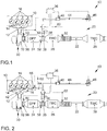
- FIG. 1 shows a schematic representation of an internal combustion engine 10, the outlet 12 of which is connected to an exhaust system 20.
- the internal combustion engine 10 is designed as a gasoline engine which is externally ignited by means of spark plugs 16 and has a plurality of combustion chambers 14.
- the internal combustion engine 10 is preferably designed as an internal combustion engine 10 charged by means of an exhaust gas turbocharger 30, a turbine 32 of the exhaust gas turbocharger 30 downstream of the outlet 12 and upstream of the first emission-reducing exhaust gas aftertreatment component, in particular upstream of a particle filter 24, is arranged.
- the exhaust system 20 comprises an exhaust gas duct 22 in which, in the flow direction of an exhaust gas through the exhaust gas duct 22, a particle filter 24, downstream of the particle filter 24 a first three-way catalytic converter 26, and further downstream a second three-way catalytic converter 28 are arranged.
- the particle filter 24 and the first three-way catalytic converter 26 are preferably each arranged close to the engine, that is, at a distance of less than 80 cm exhaust gas run length, in particular less than 50 cm exhaust gas run length, from the outlet 12 of the internal combustion engine 10.
- the second three-way catalytic converter 28 is preferably arranged in the underbody position of a motor vehicle and thus in a position remote from the engine, that is, at a distance of more than 100 cm of the exhaust gas run length from the outlet 12 of the internal combustion engine. Downstream of the particle filter 24 and upstream of the first three-way catalytic converter 26, there is an inlet point 38 for hot exhaust gases from an exhaust gas burner 34, via which the first three-way catalytic converter 26, which is arranged downstream of the inlet point 38, is heated regardless of the operating situation of the internal combustion engine 10 can.
- Additional catalytic converters in particular a further three-way catalytic converter, a NOx storage catalytic converter or a catalytic converter for the selective catalytic reduction of nitrogen oxides can also be arranged in the exhaust system 20.
- a first lambda probe 50 is arranged in the exhaust gas duct 22 upstream of the particle filter 24, with which the oxygen content ⁇ 1 of the exhaust gas can be determined downstream of the outlet 12 and upstream of the first exhaust gas aftertreatment component, i.e. the particle filter 24.
- a second lambda probe 52 Downstream of the first three-way catalytic converter 26 and upstream of the second three-way catalytic converter 28, a second lambda probe 52 is arranged in the exhaust gas duct 22, with which the oxygen content ⁇ 2 in the exhaust gas duct 28 downstream of the first three-way catalytic converter 26 and upstream of the second three-way catalyst 28 can be determined.
- the first lambda probe 50 is preferably designed as a broadband lambda probe and is connected to a control device 36 of the internal combustion engine 10 via a first signal line 60.
- the second lambda probe 52 is preferably designed as a jump probe and is connected to the control unit 36 via a second signal line 62.
- the first lambda probe 50 and the second lambda probe 52 form a sensor arrangement with which the combustion air ratio ⁇ of the internal combustion engine 10 can be regulated.
- an on-board diagnosis of the first three-way catalytic converter 26 can take place via the sensor arrangement.
- the exhaust gas burner 34 is via a secondary air system 40 with fresh air and via the fuel system of the internal combustion engine 10 or a separate fuel pump with a Fuel can be supplied.
- the secondary air system 40 includes a secondary air pump 46 which is connected to the exhaust gas burner 34 via a secondary air line 44.
- a secondary air valve 48 is arranged in the secondary air line 44, with which the air supply to the exhaust gas burner 34 can be established and stopped.
- pressure sensors 56, 58 are provided upstream and downstream of the particle filter 24, with which a differential pressure measurement can be carried out across the particle filter 24 to determine the loading state of the particle filter 24.
- an on-board diagnosis of the particle filter 24 can take place via the pressure sensors 56, 58.
- FIG 2 a further embodiment of an internal combustion engine is shown with an exhaust gas aftertreatment system.
- the secondary air system 40 has an additional secondary air line 64 which connects the secondary air pump 46 to an inlet point 42 on an outlet-side cylinder head 18 of the internal combustion engine 10.
- a further secondary air valve 66 is arranged in the additional secondary air line 64 in order to be able to introduce the secondary air into an exhaust gas that is as hot as possible and thus to promote exothermic reactions with unburned fuel components.
- the introduction point 42 can also be formed at points upstream of the particle filter 24 so that the particle filter 24 and the three-way catalytic converters 26, 28 arranged downstream of the particle filter 24 can be supplied with secondary air.
- the exhaust gas of the internal combustion engine 10 is passed through the particle filter 24, the first three-way catalytic converter 26 close to the engine and the second three-way catalytic converter 28 in the underbody position, the soot particles contained in the exhaust gas being filtered out of the exhaust gas flow and the harmful exhaust gas components are converted into harmless exhaust gas components.
- the arrangement of the particulate filter 24 and the first three-way catalytic converter 26 close to the engine enables particularly rapid heating to a light-off temperature after a cold start in order to enable the gaseous pollutants to be efficiently converted as quickly as possible after the cold start .
- the particle filter 24 is preferably uncoated, in particular without a coating with an oxygen storage capacity.
- a diagnosis of the first three-way catalytic converter 26 via the lambda probes 50, 52 is thereby possible. Due to the arrangement of the particle filter 24 as the first component of the exhaust gas aftertreatment, the first three-way catalytic converter 26 is not thermally activated when the internal combustion engine 10 is operating at full load so heavily loaded that the aging of the catalytic coating of the first three-way catalytic converter 26 can be reduced.
- FIG 3 a further embodiment of an internal combustion engine 10 according to the invention is shown.
- the inlet point 38 for the hot exhaust gases of the exhaust gas burner 34 in this embodiment is downstream of the first three-way catalytic converter 26 and upstream of the second three-way catalytic converter 28.
- a third one Lambda probe 54 is provided downstream of the second three-way catalytic converter 28 for regulating the combustion air ratio ⁇ B of the exhaust gas burner 34.
- the second three-way catalytic converter 28 is heated by the exhaust gas burner 34 and thus reaches its light-off temperature T LO shortly after a cold start of the internal combustion engine 10.
- This exemplary embodiment is particularly useful in the case of tightly packed engine compartment configurations in which an arrangement of the exhaust gas burner 34 close to the engine is not possible or only possible with considerable additional effort for reasons of installation space.
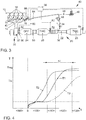
- the temperature profile is shown at several points of the exhaust system 20 when a method according to the invention for exhaust gas aftertreatment is running.
- the temperature T1 immediately downstream of the particle filter 24 is shown in a first curve I.
- the second curve II shows the temperature T2 at the first three-way catalytic converter 26 when the exhaust gas burner 34 is activated.
- the temperature T2 is determined at the center of the component of the first three-way catalytic converter 26.
- the internal combustion engine 10 is started at a starting time S and the exhaust gas burner 34 is started at the same time.
- a first phase ⁇ 100> the particle filter 24 and the first three-way catalytic converter 26 are flowed through by the exhaust gas from the internal combustion engine 10 and heated by the exhaust gas.
- the first three-way catalytic converter 26 is heated up by the hot exhaust gas from the exhaust gas burner 34, the heat from the exhaust gas burner 34 being transferred essentially convectively to the first three-way catalytic converter 26.
- T LO light-off temperature
- a third phase ⁇ 120> the exhaust gas burner 34 is switched off and the temperature of the first three-way catalytic converter 26 becomes catalytic due to the exothermic reactions of the unburned fuel components effective surface of the first three-way catalyst 26 held.
- a fourth operating phase ⁇ 130> both the first three-way catalytic converter 26 and the particle filter 24 have then reached a temperature at which no further heating measures are necessary.
- the third curve shows the temperature T3 of the first three-way catalytic converter 26 if the exhaust gas burner 34 is not activated in any of the phases ⁇ 100>, ⁇ 110> and ⁇ 120>.
- the exhaust gas burner 34 can also be activated in a pre-start phase ⁇ 90> so that the first catalytic converter 26 has already reached its light-off temperature T LO at the start S of the internal combustion engine 10 or the heating phase can be shortened again.
- an exhaust gas aftertreatment system according to the invention and the described method according to the invention can ensure that a regeneration temperature of the particle filter is reached in all driving cycles and the aging behavior of the exhaust gas aftertreatment system is reduced.
Landscapes
- Engineering & Computer Science (AREA)
- Chemical & Material Sciences (AREA)
- Combustion & Propulsion (AREA)
- Chemical Kinetics & Catalysis (AREA)
- Mechanical Engineering (AREA)
- General Engineering & Computer Science (AREA)
- Health & Medical Sciences (AREA)
- Toxicology (AREA)
- Materials Engineering (AREA)
- Biomedical Technology (AREA)
- Analytical Chemistry (AREA)
- General Chemical & Material Sciences (AREA)
- Oil, Petroleum & Natural Gas (AREA)
- Environmental & Geological Engineering (AREA)
- Exhaust Gas After Treatment (AREA)
- Processes For Solid Components From Exhaust (AREA)
Claims (10)
- Système de post-traitement de gaz d'échappement pour un moteur à combustion interne (10), comprenant un système d'échappement (20), lequel peut être raccordé à une sortie (12) du moteur à combustion interne (10), le système d'échappement (20) comprenant un canal de gaz d'échappement (22), dans lequel, dans la direction d'écoulement d'un gaz d'échappement du moteur à combustion interne (10) à travers le canal de gaz d'échappement (22), sous forme de premier composant réduisant les émissions, dans une position proche du moteur, est disposé un filtre à particules (24), en aval du filtre à particules (24), également dans une position proche du moteur, est disposé un premier catalyseur à trois voies (26) et, en aval du premier catalyseur à trois voies (26), est disposé un autre catalyseur à trois voies (28), un brûleur de gaz d'échappement (34) étant prévu en aval du filtre à particules (24), par lequel du gaz d'échappement chaud peut être introduit dans le système d'échappement (20) pour chauffer au moins un des catalyseurs à trois voies (26, 28).
- Système de post-traitement de gaz d'échappement selon la revendication 1, caractérisé en ce que le filtre à particules (24) est réalisé dépourvu d'un revêtement et/ou dépourvu d'un accumulateur d'oxygène.
- Système de post-traitement de gaz d'échappement selon la revendication 1 ou 2, caractérisé en ce que le brûleur de gaz d'échappement (34) peut être exploité avec un taux d'air de combustion (λB) variable.
- Système de post-traitement de gaz d'échappement selon la revendication 3, caractérisé en ce qu'un gaz d'échappement stœchiométrique (λ=1) est réglé en aval d'une entrée (38) du brûleur de gaz d'échappement (34).
- Système de post-traitement de gaz d'échappement selon l'une quelconque des revendications 1 à 4, caractérisé en ce que le moteur à combustion interne (10) présente un système d'air secondaire (40) pour l'introduction d'air secondaire dans le canal de gaz d'échappement (22), une entrée (42) du système d'air secondaire (40) étant disposée à la sortie (12) du moteur à combustion interne (10) ou en aval de la sortie (12) et en amont du filtre à particules (24).
- Système de post-traitement de gaz d'échappement selon l'une quelconque des revendications 1 à 5, caractérisé en ce qu'une entrée (38) des gaz d'échappement du brûleur de gaz d'échappement (34) est conçue en aval du filtre à particules (24) et en amont du premier catalyseur à trois voies (26).
- Système de post-traitement de gaz d'échappement selon l'une quelconque des revendications 1 à 6, caractérisé en ce qu'une première sonde lambda (50) est disposée en amont du filtre à particules (24) et une deuxième sonde lambda (52) est disposée en aval du premier catalyseur à trois voies (26) et en amont du deuxième catalyseur à trois voies (28) dans le canal de gaz d'échappement (22).
- Système de post-traitement de gaz d'échappement selon l'une quelconque des revendications 1 à 7, caractérisé en ce qu'un premier capteur de pression (56) est disposé en amont du filtre à particules (24) et un deuxième capteur de pression (58) est disposé en aval du filtre à particules(24).
- Procédé de post-traitement de gaz d'échappement d'un moteur à combustion interne (10) comprenant un système de post-traitement de gaz d'échappement selon l'une quelconque des revendications 1 à 8, comprenant les étapes suivantes :- chauffage d'au moins un des catalyseurs à trois voies (26, 28) à une température d'amorçage (TLO) par introduction de gaz d'échappement chauds du brûleur de gaz d'échappement (34) dans le système d'échappement (20),- chauffage du filtre à particules (24), du premier catalyseur à trois voies (26) et du deuxième catalyseur à trois voies (28) avec le flux de gaz d'échappement du moteur à combustion interne (10) à partir du démarrage du moteur à combustion interne (10).
- Procédé de post-traitement de gaz d'échappement selon la revendication 9, caractérisé en ce que, lors d'une phase de chauffage d'un des catalyseurs à trois voies (26, 28) ou du filtre à particules (24), de l'air secondaire est introduit dans la tête de cylindre (18) côté sortie ou dans le canal de gaz d'échappement (22) en aval de la sortie (12) et en amont du filtre à particules (24), pour supporter le chauffage des catalyseurs (26, 28) ou du filtre à particules (24) au moyen d'une réaction exothermique de composants de carburant non brûlés.
Applications Claiming Priority (2)
| Application Number | Priority Date | Filing Date | Title |
|---|---|---|---|
| DE102017118215.2A DE102017118215A1 (de) | 2017-08-10 | 2017-08-10 | Abgasnachbehandlungssystem und Verfahren zur Abgasnachbehandlung eines Verbrennungsmotors |
| PCT/EP2018/071602 WO2019030315A1 (fr) | 2017-08-10 | 2018-08-09 | Système et procédé de retraitement de gaz d'échappement d'un moteur à combustion interne |
Publications (2)
| Publication Number | Publication Date |
|---|---|
| EP3665371A1 EP3665371A1 (fr) | 2020-06-17 |
| EP3665371B1 true EP3665371B1 (fr) | 2020-12-02 |
Family
ID=63207741
Family Applications (1)
| Application Number | Title | Priority Date | Filing Date |
|---|---|---|---|
| EP18755172.6A Not-in-force EP3665371B1 (fr) | 2017-08-10 | 2018-08-09 | Système et procédé de posttraitement de gaz d'échappement d'un moteur à combustion interne |
Country Status (5)
| Country | Link |
|---|---|
| US (1) | US11193411B2 (fr) |
| EP (1) | EP3665371B1 (fr) |
| CN (1) | CN110945220A (fr) |
| DE (1) | DE102017118215A1 (fr) |
| WO (1) | WO2019030315A1 (fr) |
Cited By (1)
| Publication number | Priority date | Publication date | Assignee | Title |
|---|---|---|---|---|
| IT202200023415A1 (it) * | 2022-11-14 | 2024-05-14 | Ngv Powertrain | Sistema di generazione di potenza meccanica comprendente un motore a ciclo otto ed un sistema di post trattamento (ats) di gas esausto |
Families Citing this family (24)
| Publication number | Priority date | Publication date | Assignee | Title |
|---|---|---|---|---|
| DE102017118215A1 (de) | 2017-08-10 | 2019-02-14 | Volkswagen Ag | Abgasnachbehandlungssystem und Verfahren zur Abgasnachbehandlung eines Verbrennungsmotors |
| DE102018119156A1 (de) * | 2018-08-07 | 2020-02-13 | Volkswagen Aktiengesellschaft | Verfahren und Vorrichtung zur Abgasnachbehandlung eines Verbrennungsmotors |
| WO2020193281A1 (fr) * | 2019-03-25 | 2020-10-01 | Vitesco Technologies GmbH | Procédé et dispositif de régénération d'un filtre à particules à revêtement dans le système d'échappement d'un véhicule automobile à essence |
| DE102019219892A1 (de) * | 2019-03-25 | 2020-10-01 | Vitesco Technologies GmbH | Verfahren und Vorrichtung zur Regeneration eines beschichteten Partikelfilters im Abgastrakt eines benzinbetriebenen Kraftfahrzeugs |
| DE102019117755B4 (de) * | 2019-07-02 | 2023-10-12 | Dr. Ing. H.C. F. Porsche Aktiengesellschaft | Abgasnachbehandlungssystem und Verfahren zur Abgasnachbehandlung eines Verbrennungsmotors |
| DE102019121428A1 (de) | 2019-08-08 | 2021-02-11 | Volkswagen Aktiengesellschaft | Verfahren zum Aufheizen eines Katalysators und Abgasnachbehandlungssystem |
| DE102019006494B4 (de) * | 2019-09-13 | 2024-03-28 | Daimler Truck AG | Abgasanlage für eine Verbrennungskraftmaschine eines Kraftfahrzeugs, Antriebseinrichtung für ein Kraftfahrzeug sowie Kraftfahrzeug |
| DE102020202136A1 (de) * | 2020-02-19 | 2021-08-19 | Robert Bosch Gesellschaft mit beschränkter Haftung | Lambdakompensation mit Abgasbrenner |
| KR20220006310A (ko) * | 2020-07-08 | 2022-01-17 | 현대자동차주식회사 | 배출 가스 정화 장치 및 그 제어 방법 |
| CN111997719B (zh) * | 2020-09-07 | 2022-03-01 | 潍柴动力股份有限公司 | 一种三元催化器热管理系统 |
| DE102020128503B4 (de) * | 2020-10-29 | 2022-05-25 | Dr. Ing. H.C. F. Porsche Aktiengesellschaft | Abgasstrang für ein Kraftfahrzeug, Verfahren zum Betrieb eines Abgasstranges, Kraftfahrzeug |
| DE102020007000A1 (de) | 2020-11-16 | 2022-05-19 | Daimler Ag | Verbrennungskraftmaschine für ein Kraftfahrzeug, insbesondere für einen Kraftwagen |
| CN112901317A (zh) * | 2021-03-16 | 2021-06-04 | 安徽江淮汽车集团股份有限公司 | 三元催化器封装结构、发动机组件及汽车 |
| DE102021203097A1 (de) | 2021-03-29 | 2022-09-29 | Volkswagen Aktiengesellschaft | Verfahren zur Abgasnachbehandlung und Abgasnachbehandlungssystem |
| DE102021203096A1 (de) * | 2021-03-29 | 2022-09-29 | Volkswagen Aktiengesellschaft | Abgasnachbehandlungssystem |
| DE102021002188A1 (de) * | 2021-04-26 | 2022-10-27 | Mercedes-Benz Group AG | Verfahren zum Heizen eines Katalysators |
| DE102021113499A1 (de) * | 2021-05-26 | 2022-12-01 | Volkswagen Aktiengesellschaft | Verfahren zum Betreiben einer Verbrennungskraftmaschine |
| DE102021118802A1 (de) | 2021-07-21 | 2023-01-26 | Umicore Ag & Co. Kg | Abgasreinigungssystem zur Reinigung von Abgasen von Benzinmotoren |
| DE102021118801A1 (de) | 2021-07-21 | 2023-01-26 | Umicore Ag & Co. Kg | Abgasreinigungssystem zur Reinigung von Abgasen von Benzinmotoren |
| DE102021118803A1 (de) * | 2021-07-21 | 2023-01-26 | Umicore Ag & Co. Kg | Abgasreinigungssystem zur Reinigung von Abgasen von Benzinmotoren |
| DE102021211939B4 (de) | 2021-10-22 | 2024-12-24 | Volkswagen Aktiengesellschaft | Abgasnachbehandlungssystem für einen Verbrennungsmotor |
| CN115355077B (zh) * | 2022-09-23 | 2024-04-16 | 潍柴动力股份有限公司 | 驻车再生的控制方法、控制装置、可读存储介质及车辆 |
| KR102539410B1 (ko) * | 2022-10-26 | 2023-06-05 | 에이치케이엠엔에스(주) | 배출가스 승온을 이용한 차량 배출가스 저감장치 활성화 방법 |
| CN119825521B (zh) * | 2025-01-17 | 2025-10-24 | 潍柴动力股份有限公司 | 天然气发动机热管理方法、装置以及后处理系统 |
Family Cites Families (14)
| Publication number | Priority date | Publication date | Assignee | Title |
|---|---|---|---|---|
| JPH0533629A (ja) * | 1991-07-31 | 1993-02-09 | Toyota Motor Corp | 内燃機関の排気通路内燃焼装置 |
| JP5061861B2 (ja) * | 2007-11-21 | 2012-10-31 | トヨタ自動車株式会社 | 内燃機関の制御装置 |
| JP2009215933A (ja) * | 2008-03-10 | 2009-09-24 | Toyota Motor Corp | 内燃機関の制御装置 |
| DE102008036127A1 (de) | 2008-08-01 | 2010-02-04 | Emitec Gesellschaft Für Emissionstechnologie Mbh | Verfahren zum Betrieb einer Abgasanlage mit Lambda-Regelung |
| US8889587B2 (en) * | 2009-08-31 | 2014-11-18 | General Electric Company | Catalyst and method of manufacture |
| US8327628B2 (en) | 2009-09-29 | 2012-12-11 | Ford Global Technologies, Llc | Gasoline particulate filter regeneration and diagnostics |
| US8464523B2 (en) * | 2010-03-12 | 2013-06-18 | GM Global Technology Operations LLC | Targeted particulate matter filter regeneration system |
| US8429899B2 (en) * | 2010-08-09 | 2013-04-30 | GM Global Technology Operations LLC | Target particulate matter filter regeneration and temperature control system |
| US8839605B2 (en) * | 2011-03-30 | 2014-09-23 | GM Global Technology Operations LLC | Exhaust methane control systems and methods |
| DE102012011603A1 (de) | 2012-06-12 | 2013-12-12 | Volkswagen Aktiengesellschaft | Abgasanlage und Verfahren zum Betreiben einer solchen |
| DE102012021573A1 (de) | 2012-11-02 | 2014-05-08 | Volkswagen Ag | Verfahren zum Betreiben eines Brenners sowie Abgasanlage mit einem derart betreibbaren Brenner |
| DE102013003701A1 (de) * | 2013-03-04 | 2014-09-04 | Volkswagen Aktiengesellschaft | Verfahren zur Steuerung einer Regeneration eines Partikelfilters sowie einer zur Ausführung des Verfahrens ausgebildete Abgasanlage |
| JP5915623B2 (ja) * | 2013-11-14 | 2016-05-11 | トヨタ自動車株式会社 | 内燃機関の排気浄化システム |
| DE102017118215A1 (de) | 2017-08-10 | 2019-02-14 | Volkswagen Ag | Abgasnachbehandlungssystem und Verfahren zur Abgasnachbehandlung eines Verbrennungsmotors |
-
2017
- 2017-08-10 DE DE102017118215.2A patent/DE102017118215A1/de not_active Withdrawn
-
2018
- 2018-08-09 WO PCT/EP2018/071602 patent/WO2019030315A1/fr not_active Ceased
- 2018-08-09 EP EP18755172.6A patent/EP3665371B1/fr not_active Not-in-force
- 2018-08-09 CN CN201880048180.7A patent/CN110945220A/zh active Pending
-
2020
- 2020-01-28 US US16/774,361 patent/US11193411B2/en not_active Expired - Fee Related
Cited By (1)
| Publication number | Priority date | Publication date | Assignee | Title |
|---|---|---|---|---|
| IT202200023415A1 (it) * | 2022-11-14 | 2024-05-14 | Ngv Powertrain | Sistema di generazione di potenza meccanica comprendente un motore a ciclo otto ed un sistema di post trattamento (ats) di gas esausto |
Also Published As
| Publication number | Publication date |
|---|---|
| CN110945220A (zh) | 2020-03-31 |
| WO2019030315A1 (fr) | 2019-02-14 |
| EP3665371A1 (fr) | 2020-06-17 |
| US20200157995A1 (en) | 2020-05-21 |
| DE102017118215A1 (de) | 2019-02-14 |
| US11193411B2 (en) | 2021-12-07 |
Similar Documents
| Publication | Publication Date | Title |
|---|---|---|
| EP3665371B1 (fr) | Système et procédé de posttraitement de gaz d'échappement d'un moteur à combustion interne | |
| EP3508704B1 (fr) | Système de retraitement des gaz d'échappement et procédé de retraitement des gaz d'échappement d'un moteur à combustion interne | |
| EP3502428B1 (fr) | Système de post-traitement des gaz d'échappement et procédé de post-traitement des gaz d'échappement d'un moteur à combustion interne | |
| EP3642460B1 (fr) | Système de retraitement des gaz d'échappement et procédé pour le retraitement des gaz d'échappement d'un moteur a combustion interne | |
| EP3652420B1 (fr) | Système et méthode pour post-traitement des gaz d'échappement d'un moteur à combustion interne | |
| EP3921520B1 (fr) | Système de post-traitement de gaz d'échappement et procédé pour le post-traitement de gaz d'échappement d'un moteur à combustion interne | |
| EP3584418B1 (fr) | Système de post-traitement des gaz d'échappement et procédé de régénération d'un filtre à particules | |
| EP3581771B1 (fr) | Système de traitement de gaz d'échappement et procédé de régénération d'un filtre à particules | |
| DE102017205664A1 (de) | Abgasnachbehandlungsvorrichtung und Verfahren zur Abgasnachbehandlung eines Verbrennungsmotors | |
| DE102016110632B4 (de) | Verfahren zur Regeneration eines Partikelfilters | |
| EP2115277A1 (fr) | Procédé de régénération de filtres à particules dans le système d'échappement d'un moteur pour mélange pauvre et système d'échappement associé | |
| DE102019101576A1 (de) | Vorrichtung und Verfahren zur Abgasnachbehandlung eines Verbrennungsmotors | |
| EP3412880A1 (fr) | Methode de regeneration d'un filtre a particules dans l'echappement d'un moteur de combustion interne | |
| EP3604751B1 (fr) | Procédé de post-traitement des gaz d'échappement d'un moteur à combustion interne et système de post-traitement des gaz d'échappement | |
| EP3772576A1 (fr) | Procédé de chauffage d'un catalyseur et système de traitement ultérieur des gaz d'échappement | |
| DE102017115399A1 (de) | Abgasnachbehandlungssystem und Verfahren zur Abgasnachbehandlung eines Verbrennungsmotors | |
| EP3770386B1 (fr) | Système de post-traitement des gaz d'échappement et procédé de post-traitement des gaz d'échappement d'un moteur à combustion interne | |
| DE102015221994A1 (de) | Verfahren zum Betreiben einer aufladbaren Brennkraftmaschine und aufladbare Brennkraftmaschine | |
| DE102017101610A1 (de) | Verfahren zur Reduzierung der Kaltstart-Emissionen bei einem fremdgezündeten Verbrennungsmotor | |
| DE102019109442A1 (de) | Abgasnachbehandlungssystem sowie Verfahren zur Abgasnachbehandlung eines Verbrennungsmotors | |
| DE102019117755B4 (de) | Abgasnachbehandlungssystem und Verfahren zur Abgasnachbehandlung eines Verbrennungsmotors | |
| DE102017210880A1 (de) | Verfahren zum Aufheizen eines Katalysators in einer Abgasanlage eines Verbrennungsmotors sowie Abgasnachbehandlungssystem | |
| DE102017201399A1 (de) | Abgasnachbehandlungssystem | |
| DE102021112904A1 (de) | Verfahren zur Abgasnachbehandlung und Abgasnachbehandlungssystem | |
| DE102018210561A1 (de) | Duales LNT-System in Kombination mit einem aktiven SCR |
Legal Events
| Date | Code | Title | Description |
|---|---|---|---|
| STAA | Information on the status of an ep patent application or granted ep patent |
Free format text: STATUS: UNKNOWN |
|
| STAA | Information on the status of an ep patent application or granted ep patent |
Free format text: STATUS: THE INTERNATIONAL PUBLICATION HAS BEEN MADE |
|
| PUAI | Public reference made under article 153(3) epc to a published international application that has entered the european phase |
Free format text: ORIGINAL CODE: 0009012 |
|
| STAA | Information on the status of an ep patent application or granted ep patent |
Free format text: STATUS: REQUEST FOR EXAMINATION WAS MADE |
|
| REG | Reference to a national code |
Ref country code: DE Ref legal event code: R079 Ref document number: 502018003202 Country of ref document: DE Free format text: PREVIOUS MAIN CLASS: F01N0003100000 Ipc: F01N0003021000 |
|
| 17P | Request for examination filed |
Effective date: 20200310 |
|
| AK | Designated contracting states |
Kind code of ref document: A1 Designated state(s): AL AT BE BG CH CY CZ DE DK EE ES FI FR GB GR HR HU IE IS IT LI LT LU LV MC MK MT NL NO PL PT RO RS SE SI SK SM TR |
|
| AX | Request for extension of the european patent |
Extension state: BA ME |
|
| GRAP | Despatch of communication of intention to grant a patent |
Free format text: ORIGINAL CODE: EPIDOSNIGR1 |
|
| STAA | Information on the status of an ep patent application or granted ep patent |
Free format text: STATUS: GRANT OF PATENT IS INTENDED |
|
| RIC1 | Information provided on ipc code assigned before grant |
Ipc: F01N 3/36 20060101ALI20200529BHEP Ipc: F01N 3/021 20060101AFI20200529BHEP Ipc: F01N 9/00 20060101ALI20200529BHEP Ipc: F01N 3/025 20060101ALI20200529BHEP Ipc: F01N 3/10 20060101ALI20200529BHEP Ipc: F01N 3/20 20060101ALI20200529BHEP Ipc: F01N 13/00 20100101ALI20200529BHEP |
|
| DAV | Request for validation of the european patent (deleted) | ||
| DAX | Request for extension of the european patent (deleted) | ||
| INTG | Intention to grant announced |
Effective date: 20200707 |
|
| GRAS | Grant fee paid |
Free format text: ORIGINAL CODE: EPIDOSNIGR3 |
|
| GRAA | (expected) grant |
Free format text: ORIGINAL CODE: 0009210 |
|
| STAA | Information on the status of an ep patent application or granted ep patent |
Free format text: STATUS: THE PATENT HAS BEEN GRANTED |
|
| AK | Designated contracting states |
Kind code of ref document: B1 Designated state(s): AL AT BE BG CH CY CZ DE DK EE ES FI FR GB GR HR HU IE IS IT LI LT LU LV MC MK MT NL NO PL PT RO RS SE SI SK SM TR |
|
| REG | Reference to a national code |
Ref country code: GB Ref legal event code: FG4D Free format text: NOT ENGLISH |
|
| REG | Reference to a national code |
Ref country code: CH Ref legal event code: EP Ref country code: AT Ref legal event code: REF Ref document number: 1341165 Country of ref document: AT Kind code of ref document: T Effective date: 20201215 |
|
| REG | Reference to a national code |
Ref country code: DE Ref legal event code: R096 Ref document number: 502018003202 Country of ref document: DE |
|
| REG | Reference to a national code |
Ref country code: IE Ref legal event code: FG4D Free format text: LANGUAGE OF EP DOCUMENT: GERMAN |
|
| PG25 | Lapsed in a contracting state [announced via postgrant information from national office to epo] |
Ref country code: GR Free format text: LAPSE BECAUSE OF FAILURE TO SUBMIT A TRANSLATION OF THE DESCRIPTION OR TO PAY THE FEE WITHIN THE PRESCRIBED TIME-LIMIT Effective date: 20210303 Ref country code: NO Free format text: LAPSE BECAUSE OF FAILURE TO SUBMIT A TRANSLATION OF THE DESCRIPTION OR TO PAY THE FEE WITHIN THE PRESCRIBED TIME-LIMIT Effective date: 20210302 Ref country code: RS Free format text: LAPSE BECAUSE OF FAILURE TO SUBMIT A TRANSLATION OF THE DESCRIPTION OR TO PAY THE FEE WITHIN THE PRESCRIBED TIME-LIMIT Effective date: 20201202 Ref country code: FI Free format text: LAPSE BECAUSE OF FAILURE TO SUBMIT A TRANSLATION OF THE DESCRIPTION OR TO PAY THE FEE WITHIN THE PRESCRIBED TIME-LIMIT Effective date: 20201202 |
|
| REG | Reference to a national code |
Ref country code: NL Ref legal event code: MP Effective date: 20201202 |
|
| PG25 | Lapsed in a contracting state [announced via postgrant information from national office to epo] |
Ref country code: SE Free format text: LAPSE BECAUSE OF FAILURE TO SUBMIT A TRANSLATION OF THE DESCRIPTION OR TO PAY THE FEE WITHIN THE PRESCRIBED TIME-LIMIT Effective date: 20201202 Ref country code: PL Free format text: LAPSE BECAUSE OF FAILURE TO SUBMIT A TRANSLATION OF THE DESCRIPTION OR TO PAY THE FEE WITHIN THE PRESCRIBED TIME-LIMIT Effective date: 20201202 Ref country code: LV Free format text: LAPSE BECAUSE OF FAILURE TO SUBMIT A TRANSLATION OF THE DESCRIPTION OR TO PAY THE FEE WITHIN THE PRESCRIBED TIME-LIMIT Effective date: 20201202 Ref country code: BG Free format text: LAPSE BECAUSE OF FAILURE TO SUBMIT A TRANSLATION OF THE DESCRIPTION OR TO PAY THE FEE WITHIN THE PRESCRIBED TIME-LIMIT Effective date: 20210302 |
|
| PG25 | Lapsed in a contracting state [announced via postgrant information from national office to epo] |
Ref country code: HR Free format text: LAPSE BECAUSE OF FAILURE TO SUBMIT A TRANSLATION OF THE DESCRIPTION OR TO PAY THE FEE WITHIN THE PRESCRIBED TIME-LIMIT Effective date: 20201202 Ref country code: NL Free format text: LAPSE BECAUSE OF FAILURE TO SUBMIT A TRANSLATION OF THE DESCRIPTION OR TO PAY THE FEE WITHIN THE PRESCRIBED TIME-LIMIT Effective date: 20201202 |
|
| REG | Reference to a national code |
Ref country code: LT Ref legal event code: MG9D |
|
| PG25 | Lapsed in a contracting state [announced via postgrant information from national office to epo] |
Ref country code: EE Free format text: LAPSE BECAUSE OF FAILURE TO SUBMIT A TRANSLATION OF THE DESCRIPTION OR TO PAY THE FEE WITHIN THE PRESCRIBED TIME-LIMIT Effective date: 20201202 Ref country code: CZ Free format text: LAPSE BECAUSE OF FAILURE TO SUBMIT A TRANSLATION OF THE DESCRIPTION OR TO PAY THE FEE WITHIN THE PRESCRIBED TIME-LIMIT Effective date: 20201202 Ref country code: SM Free format text: LAPSE BECAUSE OF FAILURE TO SUBMIT A TRANSLATION OF THE DESCRIPTION OR TO PAY THE FEE WITHIN THE PRESCRIBED TIME-LIMIT Effective date: 20201202 Ref country code: SK Free format text: LAPSE BECAUSE OF FAILURE TO SUBMIT A TRANSLATION OF THE DESCRIPTION OR TO PAY THE FEE WITHIN THE PRESCRIBED TIME-LIMIT Effective date: 20201202 Ref country code: PT Free format text: LAPSE BECAUSE OF FAILURE TO SUBMIT A TRANSLATION OF THE DESCRIPTION OR TO PAY THE FEE WITHIN THE PRESCRIBED TIME-LIMIT Effective date: 20210405 Ref country code: RO Free format text: LAPSE BECAUSE OF FAILURE TO SUBMIT A TRANSLATION OF THE DESCRIPTION OR TO PAY THE FEE WITHIN THE PRESCRIBED TIME-LIMIT Effective date: 20201202 Ref country code: LT Free format text: LAPSE BECAUSE OF FAILURE TO SUBMIT A TRANSLATION OF THE DESCRIPTION OR TO PAY THE FEE WITHIN THE PRESCRIBED TIME-LIMIT Effective date: 20201202 |
|
| REG | Reference to a national code |
Ref country code: DE Ref legal event code: R097 Ref document number: 502018003202 Country of ref document: DE |
|
| PG25 | Lapsed in a contracting state [announced via postgrant information from national office to epo] |
Ref country code: IS Free format text: LAPSE BECAUSE OF FAILURE TO SUBMIT A TRANSLATION OF THE DESCRIPTION OR TO PAY THE FEE WITHIN THE PRESCRIBED TIME-LIMIT Effective date: 20210402 |
|
| PLBE | No opposition filed within time limit |
Free format text: ORIGINAL CODE: 0009261 |
|
| STAA | Information on the status of an ep patent application or granted ep patent |
Free format text: STATUS: NO OPPOSITION FILED WITHIN TIME LIMIT |
|
| PG25 | Lapsed in a contracting state [announced via postgrant information from national office to epo] |
Ref country code: AL Free format text: LAPSE BECAUSE OF FAILURE TO SUBMIT A TRANSLATION OF THE DESCRIPTION OR TO PAY THE FEE WITHIN THE PRESCRIBED TIME-LIMIT Effective date: 20201202 Ref country code: IT Free format text: LAPSE BECAUSE OF FAILURE TO SUBMIT A TRANSLATION OF THE DESCRIPTION OR TO PAY THE FEE WITHIN THE PRESCRIBED TIME-LIMIT Effective date: 20201202 |
|
| 26N | No opposition filed |
Effective date: 20210903 |
|
| REG | Reference to a national code |
Ref country code: DE Ref legal event code: R082 Ref document number: 502018003202 Country of ref document: DE |
|
| PG25 | Lapsed in a contracting state [announced via postgrant information from national office to epo] |
Ref country code: DK Free format text: LAPSE BECAUSE OF FAILURE TO SUBMIT A TRANSLATION OF THE DESCRIPTION OR TO PAY THE FEE WITHIN THE PRESCRIBED TIME-LIMIT Effective date: 20201202 Ref country code: SI Free format text: LAPSE BECAUSE OF FAILURE TO SUBMIT A TRANSLATION OF THE DESCRIPTION OR TO PAY THE FEE WITHIN THE PRESCRIBED TIME-LIMIT Effective date: 20201202 |
|
| PG25 | Lapsed in a contracting state [announced via postgrant information from national office to epo] |
Ref country code: ES Free format text: LAPSE BECAUSE OF FAILURE TO SUBMIT A TRANSLATION OF THE DESCRIPTION OR TO PAY THE FEE WITHIN THE PRESCRIBED TIME-LIMIT Effective date: 20201202 |
|
| REG | Reference to a national code |
Ref country code: CH Ref legal event code: PL |
|
| PG25 | Lapsed in a contracting state [announced via postgrant information from national office to epo] |
Ref country code: MC Free format text: LAPSE BECAUSE OF FAILURE TO SUBMIT A TRANSLATION OF THE DESCRIPTION OR TO PAY THE FEE WITHIN THE PRESCRIBED TIME-LIMIT Effective date: 20201202 |
|
| REG | Reference to a national code |
Ref country code: BE Ref legal event code: MM Effective date: 20210831 |
|
| PG25 | Lapsed in a contracting state [announced via postgrant information from national office to epo] |
Ref country code: LI Free format text: LAPSE BECAUSE OF NON-PAYMENT OF DUE FEES Effective date: 20210831 Ref country code: CH Free format text: LAPSE BECAUSE OF NON-PAYMENT OF DUE FEES Effective date: 20210831 |
|
| PG25 | Lapsed in a contracting state [announced via postgrant information from national office to epo] |
Ref country code: IS Free format text: LAPSE BECAUSE OF FAILURE TO SUBMIT A TRANSLATION OF THE DESCRIPTION OR TO PAY THE FEE WITHIN THE PRESCRIBED TIME-LIMIT Effective date: 20210402 Ref country code: LU Free format text: LAPSE BECAUSE OF NON-PAYMENT OF DUE FEES Effective date: 20210809 |
|
| PG25 | Lapsed in a contracting state [announced via postgrant information from national office to epo] |
Ref country code: IE Free format text: LAPSE BECAUSE OF NON-PAYMENT OF DUE FEES Effective date: 20210809 Ref country code: BE Free format text: LAPSE BECAUSE OF NON-PAYMENT OF DUE FEES Effective date: 20210831 |
|
| P01 | Opt-out of the competence of the unified patent court (upc) registered |
Effective date: 20230523 |
|
| PG25 | Lapsed in a contracting state [announced via postgrant information from national office to epo] |
Ref country code: CY Free format text: LAPSE BECAUSE OF FAILURE TO SUBMIT A TRANSLATION OF THE DESCRIPTION OR TO PAY THE FEE WITHIN THE PRESCRIBED TIME-LIMIT Effective date: 20201202 |
|
| PG25 | Lapsed in a contracting state [announced via postgrant information from national office to epo] |
Ref country code: HU Free format text: LAPSE BECAUSE OF FAILURE TO SUBMIT A TRANSLATION OF THE DESCRIPTION OR TO PAY THE FEE WITHIN THE PRESCRIBED TIME-LIMIT; INVALID AB INITIO Effective date: 20180809 |
|
| PGFP | Annual fee paid to national office [announced via postgrant information from national office to epo] |
Ref country code: GB Payment date: 20230822 Year of fee payment: 6 |
|
| PGFP | Annual fee paid to national office [announced via postgrant information from national office to epo] |
Ref country code: FR Payment date: 20230824 Year of fee payment: 6 Ref country code: DE Payment date: 20230831 Year of fee payment: 6 |
|
| PG25 | Lapsed in a contracting state [announced via postgrant information from national office to epo] |
Ref country code: MK Free format text: LAPSE BECAUSE OF FAILURE TO SUBMIT A TRANSLATION OF THE DESCRIPTION OR TO PAY THE FEE WITHIN THE PRESCRIBED TIME-LIMIT Effective date: 20201202 |
|
| PG25 | Lapsed in a contracting state [announced via postgrant information from national office to epo] |
Ref country code: TR Free format text: LAPSE BECAUSE OF FAILURE TO SUBMIT A TRANSLATION OF THE DESCRIPTION OR TO PAY THE FEE WITHIN THE PRESCRIBED TIME-LIMIT Effective date: 20201202 |
|
| PG25 | Lapsed in a contracting state [announced via postgrant information from national office to epo] |
Ref country code: MT Free format text: LAPSE BECAUSE OF FAILURE TO SUBMIT A TRANSLATION OF THE DESCRIPTION OR TO PAY THE FEE WITHIN THE PRESCRIBED TIME-LIMIT Effective date: 20201202 |
|
| REG | Reference to a national code |
Ref country code: AT Ref legal event code: MM01 Ref document number: 1341165 Country of ref document: AT Kind code of ref document: T Effective date: 20230809 |
|
| PG25 | Lapsed in a contracting state [announced via postgrant information from national office to epo] |
Ref country code: AT Free format text: LAPSE BECAUSE OF NON-PAYMENT OF DUE FEES Effective date: 20230809 |
|
| PG25 | Lapsed in a contracting state [announced via postgrant information from national office to epo] |
Ref country code: AT Free format text: LAPSE BECAUSE OF NON-PAYMENT OF DUE FEES Effective date: 20230809 |
|
| REG | Reference to a national code |
Ref country code: DE Ref legal event code: R119 Ref document number: 502018003202 Country of ref document: DE |
|
| GBPC | Gb: european patent ceased through non-payment of renewal fee |
Effective date: 20240809 |
|
| PG25 | Lapsed in a contracting state [announced via postgrant information from national office to epo] |
Ref country code: DE Free format text: LAPSE BECAUSE OF NON-PAYMENT OF DUE FEES Effective date: 20250301 |
|
| PG25 | Lapsed in a contracting state [announced via postgrant information from national office to epo] |
Ref country code: GB Free format text: LAPSE BECAUSE OF NON-PAYMENT OF DUE FEES Effective date: 20240809 |
|
| PG25 | Lapsed in a contracting state [announced via postgrant information from national office to epo] |
Ref country code: FR Free format text: LAPSE BECAUSE OF NON-PAYMENT OF DUE FEES Effective date: 20240831 |
|
| PGFP | Annual fee paid to national office [announced via postgrant information from national office to epo] |
Ref country code: AT Payment date: 20260410 Year of fee payment: 5 |