EP3665399B1 - Amortisseur à fluide pour parties de meubles réglables les unes par rapport aux autres pourvu d'un piston guidé de manière réglable dans un cylindre - Google Patents
Amortisseur à fluide pour parties de meubles réglables les unes par rapport aux autres pourvu d'un piston guidé de manière réglable dans un cylindre Download PDFInfo
- Publication number
- EP3665399B1 EP3665399B1 EP18762014.1A EP18762014A EP3665399B1 EP 3665399 B1 EP3665399 B1 EP 3665399B1 EP 18762014 A EP18762014 A EP 18762014A EP 3665399 B1 EP3665399 B1 EP 3665399B1
- Authority
- EP
- European Patent Office
- Prior art keywords
- piston
- fluid damper
- cylinder
- fluid
- sleeve
- Prior art date
- Legal status (The legal status is an assumption and is not a legal conclusion. Google has not performed a legal analysis and makes no representation as to the accuracy of the status listed.)
- Active
Links
Images


Classifications
-
- F—MECHANICAL ENGINEERING; LIGHTING; HEATING; WEAPONS; BLASTING
- F16—ENGINEERING ELEMENTS AND UNITS; GENERAL MEASURES FOR PRODUCING AND MAINTAINING EFFECTIVE FUNCTIONING OF MACHINES OR INSTALLATIONS; THERMAL INSULATION IN GENERAL
- F16F—SPRINGS; SHOCK-ABSORBERS; MEANS FOR DAMPING VIBRATION
- F16F9/00—Springs, vibration-dampers, shock-absorbers, or similarly-constructed movement-dampers using a fluid or the equivalent as damping medium
- F16F9/32—Details
- F16F9/50—Special means providing automatic damping adjustment, i.e. self-adjustment of damping by particular sliding movements of a valve element, other than flexions or displacement of valve discs; Special means providing self-adjustment of spring characteristics
- F16F9/512—Means responsive to load action, i.e. static load on the damper or dynamic fluid pressure changes in the damper, e.g. due to changes in velocity
-
- E—FIXED CONSTRUCTIONS
- E05—LOCKS; KEYS; WINDOW OR DOOR FITTINGS; SAFES
- E05F—DEVICES FOR MOVING WINGS INTO OPEN OR CLOSED POSITION; CHECKS FOR WINGS; WING FITTINGS NOT OTHERWISE PROVIDED FOR, CONCERNED WITH THE FUNCTIONING OF THE WING
- E05F3/00—Closers or openers with braking devices, e.g. checks; Construction of pneumatic or liquid braking devices
- E05F3/04—Closers or openers with braking devices, e.g. checks; Construction of pneumatic or liquid braking devices with liquid piston brakes
- E05F3/12—Special devices controlling the circulation of the liquid, e.g. valve arrangement
-
- E—FIXED CONSTRUCTIONS
- E05—LOCKS; KEYS; WINDOW OR DOOR FITTINGS; SAFES
- E05F—DEVICES FOR MOVING WINGS INTO OPEN OR CLOSED POSITION; CHECKS FOR WINGS; WING FITTINGS NOT OTHERWISE PROVIDED FOR, CONCERNED WITH THE FUNCTIONING OF THE WING
- E05F5/00—Braking devices, e.g. checks; Stops; Buffers
- E05F5/02—Braking devices, e.g. checks; Stops; Buffers specially for preventing the slamming of swinging wings during final closing movement, e.g. jamb stops
-
- F—MECHANICAL ENGINEERING; LIGHTING; HEATING; WEAPONS; BLASTING
- F16—ENGINEERING ELEMENTS AND UNITS; GENERAL MEASURES FOR PRODUCING AND MAINTAINING EFFECTIVE FUNCTIONING OF MACHINES OR INSTALLATIONS; THERMAL INSULATION IN GENERAL
- F16F—SPRINGS; SHOCK-ABSORBERS; MEANS FOR DAMPING VIBRATION
- F16F9/00—Springs, vibration-dampers, shock-absorbers, or similarly-constructed movement-dampers using a fluid or the equivalent as damping medium
- F16F9/10—Springs, vibration-dampers, shock-absorbers, or similarly-constructed movement-dampers using a fluid or the equivalent as damping medium using liquid only; using a fluid of which the nature is immaterial
- F16F9/14—Devices with one or more members, e.g. pistons, vanes, moving to and fro in chambers and using throttling effect
- F16F9/16—Devices with one or more members, e.g. pistons, vanes, moving to and fro in chambers and using throttling effect involving only straight-line movement of the effective parts
- F16F9/18—Devices with one or more members, e.g. pistons, vanes, moving to and fro in chambers and using throttling effect involving only straight-line movement of the effective parts with a closed cylinder and a piston separating two or more working spaces therein
- F16F9/19—Devices with one or more members, e.g. pistons, vanes, moving to and fro in chambers and using throttling effect involving only straight-line movement of the effective parts with a closed cylinder and a piston separating two or more working spaces therein with a single cylinder and of single-tube type
-
- F—MECHANICAL ENGINEERING; LIGHTING; HEATING; WEAPONS; BLASTING
- F16—ENGINEERING ELEMENTS AND UNITS; GENERAL MEASURES FOR PRODUCING AND MAINTAINING EFFECTIVE FUNCTIONING OF MACHINES OR INSTALLATIONS; THERMAL INSULATION IN GENERAL
- F16F—SPRINGS; SHOCK-ABSORBERS; MEANS FOR DAMPING VIBRATION
- F16F9/00—Springs, vibration-dampers, shock-absorbers, or similarly-constructed movement-dampers using a fluid or the equivalent as damping medium
- F16F9/32—Details
- F16F9/3207—Constructional features
- F16F9/3214—Constructional features of pistons
-
- F—MECHANICAL ENGINEERING; LIGHTING; HEATING; WEAPONS; BLASTING
- F16—ENGINEERING ELEMENTS AND UNITS; GENERAL MEASURES FOR PRODUCING AND MAINTAINING EFFECTIVE FUNCTIONING OF MACHINES OR INSTALLATIONS; THERMAL INSULATION IN GENERAL
- F16F—SPRINGS; SHOCK-ABSORBERS; MEANS FOR DAMPING VIBRATION
- F16F9/00—Springs, vibration-dampers, shock-absorbers, or similarly-constructed movement-dampers using a fluid or the equivalent as damping medium
- F16F9/32—Details
- F16F9/50—Special means providing automatic damping adjustment, i.e. self-adjustment of damping by particular sliding movements of a valve element, other than flexions or displacement of valve discs; Special means providing self-adjustment of spring characteristics
- F16F9/516—Special means providing automatic damping adjustment, i.e. self-adjustment of damping by particular sliding movements of a valve element, other than flexions or displacement of valve discs; Special means providing self-adjustment of spring characteristics resulting in the damping effects during contraction being different from the damping effects during extension, i.e. responsive to the direction of movement
-
- A—HUMAN NECESSITIES
- A47—FURNITURE; DOMESTIC ARTICLES OR APPLIANCES; COFFEE MILLS; SPICE MILLS; SUCTION CLEANERS IN GENERAL
- A47B—TABLES; DESKS; OFFICE FURNITURE; CABINETS; DRAWERS; GENERAL DETAILS OF FURNITURE
- A47B2210/00—General construction of drawers, guides and guide devices
- A47B2210/0091—Drawer movement damping
- A47B2210/0094—Drawer damping device with 2 relatively movable parts to convert kinetic energy
-
- E—FIXED CONSTRUCTIONS
- E05—LOCKS; KEYS; WINDOW OR DOOR FITTINGS; SAFES
- E05F—DEVICES FOR MOVING WINGS INTO OPEN OR CLOSED POSITION; CHECKS FOR WINGS; WING FITTINGS NOT OTHERWISE PROVIDED FOR, CONCERNED WITH THE FUNCTIONING OF THE WING
- E05F5/00—Braking devices, e.g. checks; Stops; Buffers
- E05F5/06—Buffers or stops limiting opening of swinging wings, e.g. floor or wall stops
- E05F5/10—Buffers or stops limiting opening of swinging wings, e.g. floor or wall stops with piston brakes
-
- E—FIXED CONSTRUCTIONS
- E05—LOCKS; KEYS; WINDOW OR DOOR FITTINGS; SAFES
- E05Y—INDEXING SCHEME ASSOCIATED WITH SUBCLASSES E05D AND E05F, RELATING TO CONSTRUCTION ELEMENTS, ELECTRIC CONTROL, POWER SUPPLY, POWER SIGNAL OR TRANSMISSION, USER INTERFACES, MOUNTING OR COUPLING, DETAILS, ACCESSORIES, AUXILIARY OPERATIONS NOT OTHERWISE PROVIDED FOR, APPLICATION THEREOF
- E05Y2201/00—Constructional elements; Accessories therefor
- E05Y2201/20—Brakes; Disengaging means; Holders; Stops; Valves; Accessories therefor
- E05Y2201/21—Brakes
-
- E—FIXED CONSTRUCTIONS
- E05—LOCKS; KEYS; WINDOW OR DOOR FITTINGS; SAFES
- E05Y—INDEXING SCHEME ASSOCIATED WITH SUBCLASSES E05D AND E05F, RELATING TO CONSTRUCTION ELEMENTS, ELECTRIC CONTROL, POWER SUPPLY, POWER SIGNAL OR TRANSMISSION, USER INTERFACES, MOUNTING OR COUPLING, DETAILS, ACCESSORIES, AUXILIARY OPERATIONS NOT OTHERWISE PROVIDED FOR, APPLICATION THEREOF
- E05Y2201/00—Constructional elements; Accessories therefor
- E05Y2201/20—Brakes; Disengaging means; Holders; Stops; Valves; Accessories therefor
- E05Y2201/262—Type of motion, e.g. braking
- E05Y2201/264—Type of motion, e.g. braking linear
-
- E—FIXED CONSTRUCTIONS
- E05—LOCKS; KEYS; WINDOW OR DOOR FITTINGS; SAFES
- E05Y—INDEXING SCHEME ASSOCIATED WITH SUBCLASSES E05D AND E05F, RELATING TO CONSTRUCTION ELEMENTS, ELECTRIC CONTROL, POWER SUPPLY, POWER SIGNAL OR TRANSMISSION, USER INTERFACES, MOUNTING OR COUPLING, DETAILS, ACCESSORIES, AUXILIARY OPERATIONS NOT OTHERWISE PROVIDED FOR, APPLICATION THEREOF
- E05Y2600/00—Mounting or coupling arrangements for elements provided for in this subclass
- E05Y2600/50—Mounting methods; Positioning
- E05Y2600/52—Toolless
- E05Y2600/53—Snapping
-
- E—FIXED CONSTRUCTIONS
- E05—LOCKS; KEYS; WINDOW OR DOOR FITTINGS; SAFES
- E05Y—INDEXING SCHEME ASSOCIATED WITH SUBCLASSES E05D AND E05F, RELATING TO CONSTRUCTION ELEMENTS, ELECTRIC CONTROL, POWER SUPPLY, POWER SIGNAL OR TRANSMISSION, USER INTERFACES, MOUNTING OR COUPLING, DETAILS, ACCESSORIES, AUXILIARY OPERATIONS NOT OTHERWISE PROVIDED FOR, APPLICATION THEREOF
- E05Y2900/00—Application of doors, windows, wings or fittings thereof
- E05Y2900/20—Application of doors, windows, wings or fittings thereof for furniture, e.g. cabinets
-
- F—MECHANICAL ENGINEERING; LIGHTING; HEATING; WEAPONS; BLASTING
- F16—ENGINEERING ELEMENTS AND UNITS; GENERAL MEASURES FOR PRODUCING AND MAINTAINING EFFECTIVE FUNCTIONING OF MACHINES OR INSTALLATIONS; THERMAL INSULATION IN GENERAL
- F16F—SPRINGS; SHOCK-ABSORBERS; MEANS FOR DAMPING VIBRATION
- F16F2222/00—Special physical effects, e.g. nature of damping effects
- F16F2222/12—Fluid damping
-
- F—MECHANICAL ENGINEERING; LIGHTING; HEATING; WEAPONS; BLASTING
- F16—ENGINEERING ELEMENTS AND UNITS; GENERAL MEASURES FOR PRODUCING AND MAINTAINING EFFECTIVE FUNCTIONING OF MACHINES OR INSTALLATIONS; THERMAL INSULATION IN GENERAL
- F16F—SPRINGS; SHOCK-ABSORBERS; MEANS FOR DAMPING VIBRATION
- F16F2232/00—Nature of movement
- F16F2232/06—Translation-to-rotary conversion
-
- F—MECHANICAL ENGINEERING; LIGHTING; HEATING; WEAPONS; BLASTING
- F16—ENGINEERING ELEMENTS AND UNITS; GENERAL MEASURES FOR PRODUCING AND MAINTAINING EFFECTIVE FUNCTIONING OF MACHINES OR INSTALLATIONS; THERMAL INSULATION IN GENERAL
- F16F—SPRINGS; SHOCK-ABSORBERS; MEANS FOR DAMPING VIBRATION
- F16F9/00—Springs, vibration-dampers, shock-absorbers, or similarly-constructed movement-dampers using a fluid or the equivalent as damping medium
- F16F9/32—Details
- F16F9/34—Special valve constructions; Shape or construction of throttling passages
- F16F9/3405—Throttling passages in or on piston body, e.g. slots
Definitions
- the invention relates to a fluid damper, i.e. a damper with fluid, for mutually adjustable furniture parts with a piston guided in an adjustable manner in a cylinder according to the preamble of claim 1.
- the piston is connected to a piston rod that is led out of the cylinder.
- the piston rod can be brought into contact with the adjustable furniture part.
- the cylinder is connected to the fixed furniture part with the piston rod-free closed end.
- a passage opening for a fluid located in the cylinder is provided in the piston.
- the piston closes on the piston rotatably mounted wing progressively moves the passage opening in the piston.
- a spring returns the wing on the piston and opens the passage opening.
- the cylinder is closed on the open end with a closure part.
- the piston has a vertical cylindrical part which extends in the axial direction of the piston rod over the entire height of the wing as viewed in the axial direction. This vertical cylindrical part has a circular section as a cutting plane when viewed across the height of the wing.
- the wing and the spring that resets it must be inserted into a recess in the piston while the piston rod is being inserted into the piston.
- the piston rod must then be pushed to the end of the piston through a central opening in the spring and the wing at the same time, which requires a lot of assembly effort and skill.
- a fluid damper is also known.
- at least one overload opening in the piston and/or between the piston and cylinder be opened above a threshold value of the pressure applied to the fluid damper. This ensures that no damper bounce occurs.
- a hard closing of the furniture parts is prevented without the threshold value of the pressurization being reached through a special design of the passage opening in the piston or between the piston and cylinder and without having to choose special shapes and sizes of the passage openings.
- a movement-controlling device with a piston which is adjustable in a cylinder is known.
- a passage opening for fluid flowing through is provided in the piston.
- the piston points spring-loaded wings that interact with the passage opening. The interaction ensures that when the piston is at a standstill, the passage opening is closed and is only opened against a high initial pressure. Once released, the necessary pressure on the piston rod is reduced. If you stop again at any position, the high initial pressure is necessary again.
- the movement-controlling device is not suitable as a fluid damper for furniture parts that can be adjusted relative to one another because it would result in constant damper bouncing and the furniture parts hitting hard when closing.
- a fluid damper for furniture parts that can be adjusted relative to one another.
- the fluid damper comprises a piston which is adjustable in a cylinder.
- a passage opening for fluid flowing through is provided in the piston.
- a wing rotatably mounted on the piston increasingly closes the passage opening.
- the fluid damper comprises a piston which is adjustable in a cylinder.
- a passage opening for fluid flowing through is provided in the piston.
- a cover element is rotatably arranged on the piston rod.
- a rotation in one direction results in an increasing closing of the passage opening and a rotation in the opposite direction results in an increasing opening.
- a rotating element is connected to the cover element. If the rotating element slides along the piston rod, it rotates the cover element.
- a restoring element is arranged between the rotary element and the cover element, which returns the rotary element to its starting position, accompanied by opening the passage opening.
- the fluid damper comprises a piston which is adjustable in a cylinder.
- a passage opening for fluid flowing through is provided in the piston.
- the fluid damper includes a valve element made of elastomer.
- a vibration damper with a hydraulic pull stop which has a cylinder tube with a working chamber, a piston rod, a piston and a cylinder tube.
- the object of the invention is to further improve the fluid damper according to the preamble of claim 1.
- the task is solved by the features of claim 1.
- the piston and the spring-loaded closing element can be pre-assembled with its sleeve, which is arranged such that it can be rotated radially relative to the piston and is held in transverse grooves of the piston.
- the transverse grooves can, for example, be designed as guide elements designed as radially projecting cams and can be moved independently of the piston rod.
- the transverse grooves allow the sleeve to be rotated radially relative to the piston.
- the length of the transverse grooves in the circumferential direction determines the twisting range.
- the sleeve In the longitudinal direction axial to the longitudinal extent of the piston and the piston rod carrying it, the sleeve is held immovably relative to the piston by the guide elements engaging in the transverse grooves.
- a spring that generates the spring load can, for example, be inserted between the sleeve and piston during the pre-assembly of the sleeve and piston.
- It can be subsequently, for example after pre-assembly of the sleeve and piston, either inserted between the sleeve and piston or effectively arranged on the outside between the sleeve and piston.
- the inner end face of the closure part is adjoined by a piston-shaped, sieve-like fluid displacement element, through which the piston rod is guided and which has sieve openings on its peripheral surface and its inner end face.
- the fluid displacement element is preferably displaceably arranged coaxially to the longitudinal axis of the piston rod, for example displaceably arranged on the piston rod.
- the fluid displacement element is designed as a plastic foam element.
- the sieve-like passage opening areas in the piston extend over an angle of preferably 10° - 40° of the circumference of the piston.
- the coil spring holds the sleeve in the reset position with the passage opening areas open.
- the wings close the passage opening areas in the piston except for a small cross section. The flow of fluid through the passage openings in the piston is therefore lower.
- Oil is preferably used as the fluid in the cylinder.
- the two areas of the fluid passage openings in the piston preferably extend over an angle of 10° - 40° each of the piston circumference.
- Fluid damper shown entirely or in parts for mutually adjustable furniture parts is equipped with a piston 4 which is guided in a cylinder 1 along the longitudinal axis of the cylinder.
- the piston 4 is cylindrical and its outer diameter is adapted to the inner diameter of the cylinder 1.
- the piston 4 divides the cylinder into two fluid spaces. At least one passage opening 4.1, 4.2 for fluid flowing through is provided in the piston 4 and/or between the piston 4 and the cylinder 1. As a result, when the piston 4 moves in the cylinder along its longitudinal or cylinder axis, a fluid exchange can take place between the two fluid spaces.
- the at least one passage opening 4.1, 4.2 is assigned at least one closing element which is spring-loaded relative to the piston 4.
- the closing element has a number of closing surfaces corresponding to the number of passage openings 4.1, 4.2.
- the closing element comprises a sleeve 2, which is arranged to be rotatable relative to the piston 4 against a spring load about the longitudinal axis or about an axis running parallel to this - in short: radially.
- the sleeve 2 has one of the on its circumference Number of passage openings 4.1, 4.2 corresponding number of wings 2.1, 2.2 forming or encompassing the closing surfaces; 2.1', 2.2'.
- axis in contrast to the terms shaft or piston rod, refers to a geometric axis and not a machine element.
- the wings 2.1, 2.2; 2.1', 2.2' can be brought into operative connection with the passage openings 4.1, 4.2, as described below.
- the fluid damper comprises a hollow cylindrical part of the piston 4. With its wall, this surrounds the sleeve 2 and the at least one wing 2.1, 2.2 arranged on its circumference; 2.1', 2.2' along at least part of their longitudinal axis, which extends parallel to the cylinder axis of the cylinder, completely in the radial direction.
- the longitudinal axis of the hollow cylindrical section also known as the hollow cylinder section axis Part of the piston 4 coincides with the previously mentioned longitudinal axis or runs parallel to it.
- the piston 4 in the cylinder 1 is guided in an adjustable manner along this,
- the piston has a vertical cylindrical part which extends in the axial direction of the piston rod over the entire height of the wing when viewed in the axial direction, and which has a circular section as a cutting plane when viewed over the entire height of the wing.
- the wall of the hollow cylindrical part viewed in the circumferential direction, surrounds the at least one wing 2.1, 2.2 arranged on the circumference of the sleeve 2; 2.1', 2.2' completely, at least along part of the hollow cylinder section axis which extends parallel to the longitudinal axis and/or runs parallel to it.
- the vertical cylindrical part extends completely over the height of the wing along the longitudinal axis. However, when viewed in the circumferential direction, it does not surround the wing at all or only partially.
- the hollow cylindrical part of the piston 4 due to its hollow cylindrical shape, includes the sleeve 2 and the at least one wing 2.1, 2.2; arranged on its circumference. 2.1 ', 2.2' completely surrounds at least some areas. This can preferably be the case at least along part of its longitudinal axis.
- the piston preferably surrounds the sleeve in the radial direction or in the circumferential direction of the sleeve 2.
- the longitudinal axis can extend parallel to the cylinder axis of the cylinder and can also be referred to as the hollow cylinder section axis.
- Such a latching preferably comprises a latching connection which fixes the sleeve 2 in the axial direction of the piston 4 and holds it in a radially rotatable manner.
- This can be formed, for example, by guide elements 2.3, 2.4 engaging in transverse grooves 4.3, 4.4 of the piston 4.
- transverse grooves 4.3, 4.4 can be arranged, for example, in the hollow cylindrical part of the piston 4.
- the guide elements 2.3, 2.4 can preferably be arranged radially projecting on the sleeve 2.
- the guide elements correspond to the transverse grooves in the axial direction of the longitudinal axis of the hollow cylindrical part. In the circumferential direction, the guide elements are shorter than the transverse grooves 4.3, 4.4 in order to ensure that the sleeve 2 can be rotated relative to the piston 4.
- the distribution of the guide elements 2.3, 2.4 over the outer circumference/the outside 2.5 of the sleeve 2 corresponds to the distribution of the transverse grooves 4.3, 4.4 over the inner circumference of the hollow cylindrical part of the piston 4.
- a uniform distribution over the circumference is preferably provided.
- guide elements 2.3, 2.4 can alternatively be provided on the inner circumference of the hollow cylindrical part of the piston 4 and the transverse grooves 4.3, 4.4 on the outer circumference of the sleeve 2.
- guide elements 2.3, 2.4 can be provided both on the inner circumference of the hollow cylindrical part of the piston 4 and on the outer circumference of the sleeve 2. These can be assigned transverse grooves 4.3, 4.4 on the respective counterpart.
- the closing element can only be inserted into the hollow cylindrical part of the piston 4 in exactly one orientation and rotational position and locked there by means of a corresponding coding-like arrangement of transverse grooves 4.3, 4.4 and guide elements 2.3, 2.4.
- the sleeve 2 is therefore held in a radially rotatable manner, preferably by means of guide elements 2.3, 2.4 in transverse grooves 4.3, 4.4, for example in the piston 4.
- the closing element progressively closes the passage openings 4.1, 4.2 against a pressure load on the fluid damper and releases them both when the fluid damper is not under stress and when there is a tensile load on the fluid damper.
- the closing surfaces and the flow surfaces are, as already mentioned, preferably of wings 2.1, 2.2; 2.1', 2.2' includes and/or formed.
- the wings 2.1, 2.2; 2.1', 2.2' advantageously protrude from the sleeve 2 radially to the longitudinal axis of the cylinder 1. As a result, they protrude freely into a fluid flow that occurs during a fluid exchange between the two fluid spaces, accompanied by the best possible flow around them.
- the vanes extend along an inside of the piston axially along the longitudinal axis of the cylinder.
- the wings alternatively or additionally also extend along an outside/outer circumference of the sleeve in the longitudinal direction of the cylinder, preferably between the sleeve and the piston.
- the sleeve 2 preferably carries two opposite wings 2.1, 2.2 forming the flow surfaces on its circumference in the longitudinal direction; 2.1', 2.2'.
- Their outer surfaces include the closing surfaces, which can be pushed over two passage openings 4.1, 4.2, also referred to as fluid passage areas, formed in the piston 4 and/or between the piston 4 and cylinder 1, in order to close them.
- At least two passage openings 4.1, 4.2 which are preferably evenly distributed over the circumference, are preferably provided for fluid flowing through.
- the sleeve 2 comprises flow surfaces distributed on its circumference in accordance with the arrangement of the passage openings 4.1, 4.2.
- the flow surfaces are designed in such a way that they rotate the sleeve 2 relative to the piston 4 against the spring load due to the fluid flowing around them relative to this moving piston 4 when the fluid flows around them in the opposite direction of movement along the longitudinal axis (against the first direction according to 2.) of the cylinder 1, so that the closing surfaces progressively close the passage openings 4.1, 4.2 as the relative speed increases.
- the piston 4 is advantageously connected to a piston rod 5 which is led out of the cylinder 1 and can be brought into contact with an adjustable furniture part.
- the cylinder 1 can be connected to the piston rod-free closed end and the fixed furniture part.
- a spring generating the spring load can be arranged between the piston 4 and the sleeve 2 to save space.
- the spring which is preferably designed as a coil spring 3, holds the sleeve 2 in the reset position with the passage opening areas 4.1, 4.2 open.
- the cylinder 1 of the fluid damper can be closed with a closure part 6 at its end, also referred to as the open end face, which is free of a passage for the piston rod 5.
- a piston-shaped, sieve-like fluid displacement element 7, through which the piston rod 5 is guided, can be connected to the inner end face 4 of the closure part 6.
- the fluid displacement element 7 can have sieve openings 7.1 - 7.3 on its peripheral surface and its inner end face.
- the fluid displacement element 7 can be designed, for example, as a plastic foam element.
- Sieve-like fluid passage areas 4.1, 4.2 can be provided in the piston 4, which extend over an angle of preferably 10° - 40° of the circumference of the piston 4.
- At least one compensation opening can be provided between cylinder 1 and piston 4 and/or in piston 4, which is not assigned a wing. This ensures that even at high relative speeds between piston 4 and cylinder 1, sufficient fluid exchange can take place between the two fluid spaces separated by piston 4.
- Fig. 1 the components of an exemplary embodiment of a fluid damper, which are to be arranged in the cylinder 1, are shown in a disassembled construction.
- the fluid damper shown consists of a cylinder 1, a sleeve 2, a coil spring 3, a piston 4, a piston rod 5 and a closure part 6. It is attached to a fixed furniture part with the closed end face of the cylinder 1.
- the piston 4 is arranged at the end of the piston rod 5 inserted into the cylinder 1, i.e. non-rotatably relative to the piston.
- the piston rod 5 is accessible in the piston 4.
- This carries at its end the sleeve 2, which is closed at one end and can be rotated radially on the tapered end 5.1 of the piston rod 5.
- the sleeve 2 carries on its circumference in the longitudinal direction two opposing wings 2.1 and 2.2, the outer surfaces 2.5 and 2.6 of which have two fluid opening areas 4.1 and 4.2 formed in the piston 4 (see Fig. Figures 7, 9 , 11 ) can be pushed to close them.
- the sleeve 2 also has two opposing cams 2.3 and 2.4 on its outer surface, which are guided in transverse grooves 4.3 and 4.4 of the piston 4.
- the coil spring 3 pushed onto the tapered end 5.1 is supported on the one hand on one of the wings 2.1, 2.2 and on the other hand on a stop of the piston 4 in such a way that these wings are adjusted counterclockwise so that they release the passage opening areas 4.1, 4.2 in the piston 4.
- the open end of the cylinder 1 is closed with the closure part 6, the outer diameter of which is adapted to the inner diameter of the cylinder 1.
- the piston rod 5 is led out of the cylinder 1 through the closure part 6 and can be brought into contact with the adjustable furniture part when the adjustable furniture part is closed.
- a fluid displacement element 7, for example in the form of a plastic foam element, can be arranged so that it can be adjusted coaxially to the longitudinal axis of the piston rod 5, for example it can be guided in an adjustable manner on the piston rod 5, as is the case Figures 2 - 6 , 8th and 10 show.
- the outside diameter of the piston 4 is adapted to the inside diameter of the cylinder 1 and to accommodate the piston rod 5.
- the piston 4 is fixed non-rotatably on the reduced end section 5.1 of the piston rod 5.
- the closure part 6 with the collar 6.1 forms the end of the piston rod 5.
- the Figures 2 and 3 show sleeves 2, which are provided with similarly designed wings 2.1 ', 2.2'.
- the piston has been omitted, while in the Figures 4 and 5
- the pistons 4 with the inserted sleeves 2 are also shown.
- the fluid displacement element 7 can also be seen in the form of a drum with two sieve-like openings 7.2, 7.3 on its circumference and a sieve-like opening 7.3 on its end face.
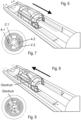
- Fig. 6 the sequence of movements when closing the furniture parts is shown at low speed of the piston rod 5.
- the main stream of fluid flows according to the cross section of the Fig. 7 through the fluid damper through two fluid opening areas 4.1, 4.2.
- the wings 2.1, 2.2 remain in a starting position. There is only a minimal braking effect.
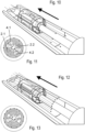
- the wings 2.1, 2.2 close the passage opening areas 4.1, 4.2 Figures 10, 11 so far that there is only a small flow cross section through the piston 4.
- the fluid flows through the external gap between the cylinder 1 and the piston 4 and causes a counterforce.
- the coil spring 3 causes the wings 2.1, 2.2 to rotate clockwise, which leads to a continuous opening of the fluid passage areas 4.1, 4.2. This leads to a reduction in piston speed and a soft stop on the furniture parts to be closed.
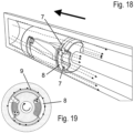
- an advantageous development of the invention provides that the restoring force of the at least one wing 2.1, 2.2, which is necessary to release the passage or fluid opening areas 4.1 and 4.2, is ensured by a spring load instead of by an internal coil spring 3 or in addition to an internal coil spring 3 by one in one Groove 7 arranged on the outer circumference of piston 4 between piston 4 and cylinder 1, torsion spring 8 inserted, for example a torsion spring or a leg spring with legs directed along the longitudinal axis.
- the groove 7 is advantageously deeper in the radial direction normal to the longitudinal axis than the inner diameter of the torsion spring 8 or the material cross section of the spring material of the torsion spring 8 would require.
- the torsion spring 8 is advantageously wound up against the restoring force when stressed. This causes their outer diameter to decrease. When the restoring force is exerted, it is unwound again, whereby its outer diameter is largest in the rest position of the piston and with the passage or fluid opening areas 4.1 and 4.2 released.
- the torsion spring 8 is now compressed during a movement against the restoring force and is thereby wound around the longitudinal axis, this creates a gap 9 between the piston 4 and the cylinder 1. Through this gap, fluid can flow past the piston 4 from one into the other fluid space. Alternatively, an already existing gap 9 is thereby enlarged.
- the spring load provided for resetting the wings 2.1, 2.2 while releasing the passage or fluid opening areas 4.1 and 4.2 is at least partially provided by a groove 7 on the circumference of the piston 4 between the piston 4 and Cylinder 1 arranged torsion spring 8 is applied. When loaded, this is wound around the longitudinal axis against the spring load and has its largest outside diameter when the piston 4 is at rest.
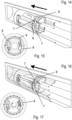
- FIG. 14 to Fig. 19 A fluid damper is shown which still functions perfectly even when the ambient temperature changes along with a change in the viscosity of a fluid in the cylinder.
- the viscosity of at least certain oils changes with a change in temperature, with the proviso that as the temperature drops, the viscosity of the oil increases.
- Fig. 14 to Fig. 19 The fluid damper shown is provided so that when conditions change, part of the flow volume otherwise passing through the passage openings 4.1, 4.2 is diverted mechanically, for example by means of a spring force, or is directed past the piston 4, for example through the middle or at the edge. This counteracts an impending change in the damping resistance.
Landscapes
- Engineering & Computer Science (AREA)
- General Engineering & Computer Science (AREA)
- Mechanical Engineering (AREA)
- Physics & Mathematics (AREA)
- Fluid Mechanics (AREA)
- Fluid-Damping Devices (AREA)
Claims (14)
- Amortisseur par fluide pour des parties réglables en concurrence, en particulier pour des parties de meubles, avec- un piston (4) guidé réglable dans un cylindre (1) tout au long d'un axe longitudinal,- au minimum une ouverture au passage (4.1, 4.2) pour le fluide s'écoulant formée dans le piston (4) et/ou dans le piston (4) et ou dans le cylindre (1),- une douille (2) avec des ailettes (2.1, 2.2; 2.1', 2.2') qui est disposée à titre pivotant et à titre relatif au niveau du piston (4) contre la contrainte élastique autour de l'axe longitudinal ou à titre parallèle s'étendant vers l'axe radial et est adaptable aux ouvertures au passage (4.1, 4.2) en liaison active est caractérisé de sorte que l'amortisseur par fluide est formé d'une partie en forme de cylindre creux du piston (4) entourant la douille (2) et que l'ailette (2.1, 2.2; 2.1', 2.2') est disposée au minimum à sa périphérie tout autour au minimum d'une partie de l'axe longitudinal à titre radial et que l'ailette (2.1, 2.2; 2.1', 2.2') est formée de sorte que l'ouverture au passage (4.1, 4.2) se ferme contre la contrainte de pression à titre progressif de l'amortisseur par fluide et que l'amortisseur par fluide se libère que ce soit au niveau de l'amortisseur par fluide non réclamé ou que ce soit lors d'un effort de traction.
- Amortisseur par fluide selon la revendication 1 est caractérisé de sorte que la douille (2) est maintenue par le biais d'une liaison à encliquetage réglable à titre radial au niveau du piston (4).
- Amortisseur par fluide selon la revendication 2 est caractérisé de sorte que la douille (2) se compose à titre relatif au niveau du piston (4) d'éléments de guidage intrusifs (2.3,2.4) en qualité de liaisons à encliquetage réglables à titre radial disposées et maintenues au niveau des rainures transversales (4.3, 4.4).
- Amortisseur par fluide selon l'une des revendications 1 jusqu'à 3 est caractérisé de sorte que le piston (4) est relié à une tige de piston (5) sortant du cylindre (1) qui est adaptable au contact avec une partie du meuble réglable.
- Amortisseur par fluide selon l'une des revendications antérieures est caractérisé de sorte que le cylindre (1) est reliable à l'extrémité fermée libre de la tige de piston à une partie du meuble fixe.
- Amortisseur par fluide selon l'une des revendications antérieures est caractérisé de sorte que la douille (2) supporte à sa périphérie dans la direction longitudinale deux ailettes opposées (2.1, 2.2; 2.1', 2.2') dont la surface extérieure est coulissante sur deux ouvertures au passage (4.1, 4.2) formées au niveau du piston (4) et/ou entre le piston (4) et le cylindre (1) en vue de leur fermeture.
- Amortisseur par fluide selon l'une des revendications antérieures est caractérisé de sorte qu'une languette (3) est disposée entre le piston (4) et la douille (2) générant la contrainte élastique.
- Amortisseur par fluide selon la revendication 7 est caractérisé de sorte que la languette (3) exécutant à titre préférable le ressort hélicoïdal (3) maintient la douille (2) en position remise à zéro dans l'ouverture au passage ouverte (4.1, 4.2).
- Amortisseur par fluide selon l'une des revendications antérieures est caractérisé de sorte que le cylindre (1) est verrouillé à l'aide d'un obturateur (6).
- Amortisseur par fluide selon la revendication 9 est caractérisé de sorte qu'un élément de déplacement de fluide de tamis en forme de piston (7) rejoint la face frontale intérieure (4) de l'obturateur (6) d'où la tige du piston (5) est guidée et qui présente sur sa surface périphérique et sur sa face frontale intérieure des ouvertures de tamis (7.1 - 7.3).
- Amortisseur par fluide selon l'une des revendications antérieures est caractérisé de sorte que l'ouverture au passage (10) au niveau du piston (1) se ferme lors du déplacement de la tige de piston (5) de la position initiale à grande vitesse d'une ailette (2.1, 2.2) au minimum jusqu'à une petite section transversale.
- Amortisseur par fluide selon l'une des revendications antérieures est caractérisé de sorte que le piston (4) est formé à titre cylindrique et est adaptable au diamètre extérieure du diamètre intérieure du cylindre (1).
- Amortisseur par fluide selon l'une des revendications antérieures est caractérisé de sorte qu'une ouverture de compensation est prévue au minimum entre le cylindre (1) et le piston (4) et/ou au niveau du piston.
- Amortisseur par fluide selon l'une des revendications antérieures est caractrisé de sorte que la contrainte élastique est appliquée au minimum et à titre partiel à travers un ressort de torsion (8) disposé dans une rainure (7) en périphérie du piston (4) entre le piston (4) et le cylindre (1).
Applications Claiming Priority (2)
| Application Number | Priority Date | Filing Date | Title |
|---|---|---|---|
| EP17185525 | 2017-08-09 | ||
| PCT/EP2018/071459 WO2019030258A1 (fr) | 2017-08-09 | 2018-08-08 | Amortisseur à fluide pour pièces réglables les unes par rapport aux autres ayant un piston guidé de manière réglable dans un cylindre |
Publications (2)
| Publication Number | Publication Date |
|---|---|
| EP3665399A1 EP3665399A1 (fr) | 2020-06-17 |
| EP3665399B1 true EP3665399B1 (fr) | 2024-01-03 |
Family
ID=59581756
Family Applications (1)
| Application Number | Title | Priority Date | Filing Date |
|---|---|---|---|
| EP18762014.1A Active EP3665399B1 (fr) | 2017-08-09 | 2018-08-08 | Amortisseur à fluide pour parties de meubles réglables les unes par rapport aux autres pourvu d'un piston guidé de manière réglable dans un cylindre |
Country Status (4)
| Country | Link |
|---|---|
| US (1) | US11959327B2 (fr) |
| EP (1) | EP3665399B1 (fr) |
| CN (1) | CN111194388B (fr) |
| WO (1) | WO2019030258A1 (fr) |
Families Citing this family (7)
| Publication number | Priority date | Publication date | Assignee | Title |
|---|---|---|---|---|
| DE102021100029A1 (de) * | 2020-05-26 | 2021-12-02 | H. Rottländer & A. Seuthe GbR (vertretungsberechtigter Gesellschafter: Hendrik Rottländer, 45277 Essen) | Arretiersystem |
| CN112576675B (zh) * | 2020-12-30 | 2024-08-13 | 赣州禾盈通用零部件有限公司 | 一种旋转阻尼器 |
| EP4457417A4 (fr) * | 2021-12-01 | 2025-12-03 | Samet Kalip Ve Madeni Esya San Ve Tic A S | Amortisseur hydraulique pour portes et tiroirs de meubles |
| CN114877007B (zh) * | 2022-05-09 | 2024-01-05 | 温州大学 | 非对称阻尼力减振器活塞组件及磁流变减振器 |
| AT526392A1 (de) * | 2022-07-26 | 2024-02-15 | Blum Gmbh Julius | Dämpfvorrichtung zum Dämpfen einer Bewegung eines bewegbaren Teiles, insbesondere Möbelteil, Fenster und/oder Türe |
| AT526393A1 (de) * | 2022-07-26 | 2024-02-15 | Blum Gmbh Julius | Dämpfvorrichtung für einen Möbel- oder Baubeschlag |
| FR3165478A1 (fr) * | 2024-08-06 | 2026-02-13 | Pierre-Louis Gourga | Système d’amortissement linéaire à aire d’écoulement variable selon le déplacement du piston dans sa chambre d’amortissement |
Family Cites Families (21)
| Publication number | Priority date | Publication date | Assignee | Title |
|---|---|---|---|---|
| US5507070A (en) * | 1994-08-31 | 1996-04-16 | Enidine, Inc. | Mechanism for closing a lid |
| GB2333574B (en) | 1998-01-23 | 2001-09-05 | Draftex Ind Ltd | Movement-controlling device |
| CN101067431B (zh) * | 2001-11-27 | 2010-09-15 | 株式会社索密克石川 | 回转式阻尼器和具备该回转式阻尼器的汽车零件以及旋转动作辅助机构 |
| MY134843A (en) | 2003-11-05 | 2007-12-31 | Harn Marketing Sdn Bhd | Fluid damper |
| DE102004008956A1 (de) | 2004-02-24 | 2005-09-01 | Volkswagen Ag | Schwingungsdämpfer mit hydraulischem Anschlag |
| WO2006029421A1 (fr) | 2004-09-17 | 2006-03-23 | Julius Blum Gmbh | Amortisseur fluidique |
| KR20090095379A (ko) * | 2008-03-05 | 2009-09-09 | (주)문주하드웨어 | 서랍용 충격완화장치 |
| ES2391506B1 (es) | 2010-03-24 | 2013-07-19 | Miguel Ángel Rioja Calvo | Dispositivo amortiguador progresivo para mobiliario. |
| US20120175830A1 (en) * | 2011-01-07 | 2012-07-12 | Ching-Chuan Yang | Buffer |
| US9169890B2 (en) * | 2011-07-21 | 2015-10-27 | Tenneco Automotive Operating Company Inc. | Low noise valve assembly |
| DE202014002228U1 (de) | 2014-03-14 | 2014-05-06 | Erwin Krüger | Fluiddämpfer für gegeneinander verstellbare Möbelteile mit einem relativ in einem Zylinder verstellbar geführten Kolben |
| US10047818B2 (en) * | 2014-05-28 | 2018-08-14 | Piolax, Inc. | Damping device |
| US10670063B2 (en) * | 2014-09-04 | 2020-06-02 | Hartwell Corporation | Hold open rod locking mechanism |
| DE102015201474A1 (de) * | 2015-01-28 | 2016-07-28 | Stabilus Gmbh | Dämpferanordnung, insbesondere für eine Klappe eines Fahrzeugs |
| DE102015109188A1 (de) | 2015-06-10 | 2016-12-15 | Samuel Grega | Kolben für einen Fluiddämpfer, der für gegeneinander verstellbare Möbelteile mit einem relativ in einem Zylinder verstellbar geführten Kolben ausgebildet ist |
| EP3577367B1 (fr) * | 2017-08-02 | 2023-06-07 | Wolfgang Held | Amortisseur à fluide pour parties de meubles réglables les unes par rapport aux autres pourvu d'un piston guidé de manière réglable dans un cylindre |
| JP6701242B2 (ja) * | 2018-02-21 | 2020-05-27 | Kyb株式会社 | バルブおよび緩衝器 |
| US11009095B2 (en) * | 2018-11-06 | 2021-05-18 | Tenneco Automotive Operating Company Inc. | Damper with monolithic base |
| CN210318310U (zh) * | 2019-05-20 | 2020-04-14 | 重庆工业职业技术学院 | 旋转底阀可调阻尼减振器 |
| CN210318314U (zh) * | 2019-05-20 | 2020-04-14 | 重庆工业职业技术学院 | 阀式可调阻尼减振器 |
| CN113074207B (zh) * | 2021-04-14 | 2022-04-29 | 北京京西重工有限公司 | 液压阻尼器 |
-
2018
- 2018-08-08 US US16/635,972 patent/US11959327B2/en active Active
- 2018-08-08 WO PCT/EP2018/071459 patent/WO2019030258A1/fr not_active Ceased
- 2018-08-08 EP EP18762014.1A patent/EP3665399B1/fr active Active
- 2018-08-08 CN CN201880065471.7A patent/CN111194388B/zh active Active
Also Published As
| Publication number | Publication date |
|---|---|
| CN111194388A (zh) | 2020-05-22 |
| US20210207416A1 (en) | 2021-07-08 |
| EP3665399A1 (fr) | 2020-06-17 |
| WO2019030258A1 (fr) | 2019-02-14 |
| CN111194388B (zh) | 2022-06-03 |
| US11959327B2 (en) | 2024-04-16 |
Similar Documents
| Publication | Publication Date | Title |
|---|---|---|
| EP2425080B1 (fr) | Amortisseur pour des meubles | |
| WO2019030258A1 (fr) | Amortisseur à fluide pour pièces réglables les unes par rapport aux autres ayant un piston guidé de manière réglable dans un cylindre | |
| EP3577367B1 (fr) | Amortisseur à fluide pour parties de meubles réglables les unes par rapport aux autres pourvu d'un piston guidé de manière réglable dans un cylindre | |
| EP2388493B1 (fr) | Amortisseur | |
| DE2903863C2 (de) | Hydraulischer Stoßdämpfer | |
| DE102014203882B4 (de) | Kolben-Zylinder-Einheit und Türscharnier mit einer Kolben-Zylinder-Einheit | |
| EP1884614B1 (fr) | Agencement de charnière | |
| WO1996026343A1 (fr) | Ferme-porte | |
| DE102005056005A1 (de) | Verstellelement | |
| WO2017064155A1 (fr) | Soupape champignon | |
| DE102009035682A1 (de) | Scharnier mit hydraulischer Dämpfungsvorrichtung | |
| EP3908755B1 (fr) | Soupape à siège | |
| EP4062082B1 (fr) | Système de verrouillage | |
| DE102015109188A1 (de) | Kolben für einen Fluiddämpfer, der für gegeneinander verstellbare Möbelteile mit einem relativ in einem Zylinder verstellbar geführten Kolben ausgebildet ist | |
| DE3615688A1 (de) | Laengenverstellbare gasfeder und betaetigungseinrichtung hierfuer | |
| AT393005B (de) | Hydraulischer drehfluegelstossdaempfer | |
| DE102008050681B4 (de) | Federbein mit treppenartigem Anschlag | |
| DE19938212C1 (de) | Hydraulischer Stoßdämpfer | |
| EP2196695B1 (fr) | Ressort à gaz réglable en longueur | |
| DE102005023942B4 (de) | Gasfeder | |
| DE102010041606B4 (de) | Dämpfventilanordnung für einen Schwingungsdämpfer | |
| DE102016101664A1 (de) | Axialventil | |
| DE102016201386B4 (de) | Gasdruckfeder | |
| DE10058432B4 (de) | Türfeststeller einer Kraftfahrzeugtür | |
| DE102020204784B4 (de) | Dämpfer, insbesondere Hydraulikdämpfer |
Legal Events
| Date | Code | Title | Description |
|---|---|---|---|
| STAA | Information on the status of an ep patent application or granted ep patent |
Free format text: STATUS: UNKNOWN |
|
| STAA | Information on the status of an ep patent application or granted ep patent |
Free format text: STATUS: THE INTERNATIONAL PUBLICATION HAS BEEN MADE |
|
| PUAI | Public reference made under article 153(3) epc to a published international application that has entered the european phase |
Free format text: ORIGINAL CODE: 0009012 |
|
| STAA | Information on the status of an ep patent application or granted ep patent |
Free format text: STATUS: REQUEST FOR EXAMINATION WAS MADE |
|
| 17P | Request for examination filed |
Effective date: 20200309 |
|
| AK | Designated contracting states |
Kind code of ref document: A1 Designated state(s): AL AT BE BG CH CY CZ DE DK EE ES FI FR GB GR HR HU IE IS IT LI LT LU LV MC MK MT NL NO PL PT RO RS SE SI SK SM TR |
|
| AX | Request for extension of the european patent |
Extension state: BA ME |
|
| DAV | Request for validation of the european patent (deleted) | ||
| DAX | Request for extension of the european patent (deleted) | ||
| STAA | Information on the status of an ep patent application or granted ep patent |
Free format text: STATUS: EXAMINATION IS IN PROGRESS |
|
| 17Q | First examination report despatched |
Effective date: 20211006 |
|
| GRAP | Despatch of communication of intention to grant a patent |
Free format text: ORIGINAL CODE: EPIDOSNIGR1 |
|
| STAA | Information on the status of an ep patent application or granted ep patent |
Free format text: STATUS: GRANT OF PATENT IS INTENDED |
|
| RIC1 | Information provided on ipc code assigned before grant |
Ipc: E05F 5/10 20060101ALN20230630BHEP Ipc: F16F 9/34 20060101ALN20230630BHEP Ipc: E05F 5/02 20060101ALI20230630BHEP Ipc: F16F 9/516 20060101ALI20230630BHEP Ipc: F16F 9/512 20060101AFI20230630BHEP |
|
| INTG | Intention to grant announced |
Effective date: 20230801 |
|
| GRAS | Grant fee paid |
Free format text: ORIGINAL CODE: EPIDOSNIGR3 |
|
| GRAA | (expected) grant |
Free format text: ORIGINAL CODE: 0009210 |
|
| STAA | Information on the status of an ep patent application or granted ep patent |
Free format text: STATUS: THE PATENT HAS BEEN GRANTED |
|
| AK | Designated contracting states |
Kind code of ref document: B1 Designated state(s): AL AT BE BG CH CY CZ DE DK EE ES FI FR GB GR HR HU IE IS IT LI LT LU LV MC MK MT NL NO PL PT RO RS SE SI SK SM TR |
|
| REG | Reference to a national code |
Ref country code: GB Ref legal event code: FG4D Free format text: NOT ENGLISH |
|
| REG | Reference to a national code |
Ref country code: DE Ref legal event code: R096 Ref document number: 502018013913 Country of ref document: DE |
|
| REG | Reference to a national code |
Ref country code: CH Ref legal event code: EP |
|
| REG | Reference to a national code |
Ref country code: IE Ref legal event code: FG4D Free format text: LANGUAGE OF EP DOCUMENT: GERMAN |
|
| REG | Reference to a national code |
Ref country code: LT Ref legal event code: MG9D |
|
| PG25 | Lapsed in a contracting state [announced via postgrant information from national office to epo] |
Ref country code: ES Free format text: LAPSE BECAUSE OF FAILURE TO SUBMIT A TRANSLATION OF THE DESCRIPTION OR TO PAY THE FEE WITHIN THE PRESCRIBED TIME-LIMIT Effective date: 20240103 |
|
| PG25 | Lapsed in a contracting state [announced via postgrant information from national office to epo] |
Ref country code: ES Free format text: LAPSE BECAUSE OF FAILURE TO SUBMIT A TRANSLATION OF THE DESCRIPTION OR TO PAY THE FEE WITHIN THE PRESCRIBED TIME-LIMIT Effective date: 20240103 |
|
| REG | Reference to a national code |
Ref country code: NL Ref legal event code: MP Effective date: 20240103 |
|
| PG25 | Lapsed in a contracting state [announced via postgrant information from national office to epo] |
Ref country code: NL Free format text: LAPSE BECAUSE OF FAILURE TO SUBMIT A TRANSLATION OF THE DESCRIPTION OR TO PAY THE FEE WITHIN THE PRESCRIBED TIME-LIMIT Effective date: 20240103 |
|
| PG25 | Lapsed in a contracting state [announced via postgrant information from national office to epo] |
Ref country code: NL Free format text: LAPSE BECAUSE OF FAILURE TO SUBMIT A TRANSLATION OF THE DESCRIPTION OR TO PAY THE FEE WITHIN THE PRESCRIBED TIME-LIMIT Effective date: 20240103 |
|
| PG25 | Lapsed in a contracting state [announced via postgrant information from national office to epo] |
Ref country code: IS Free format text: LAPSE BECAUSE OF FAILURE TO SUBMIT A TRANSLATION OF THE DESCRIPTION OR TO PAY THE FEE WITHIN THE PRESCRIBED TIME-LIMIT Effective date: 20240503 |
|
| PG25 | Lapsed in a contracting state [announced via postgrant information from national office to epo] |
Ref country code: LT Free format text: LAPSE BECAUSE OF FAILURE TO SUBMIT A TRANSLATION OF THE DESCRIPTION OR TO PAY THE FEE WITHIN THE PRESCRIBED TIME-LIMIT Effective date: 20240103 |
|
| PG25 | Lapsed in a contracting state [announced via postgrant information from national office to epo] |
Ref country code: GR Free format text: LAPSE BECAUSE OF FAILURE TO SUBMIT A TRANSLATION OF THE DESCRIPTION OR TO PAY THE FEE WITHIN THE PRESCRIBED TIME-LIMIT Effective date: 20240404 |
|
| PG25 | Lapsed in a contracting state [announced via postgrant information from national office to epo] |
Ref country code: RS Free format text: LAPSE BECAUSE OF FAILURE TO SUBMIT A TRANSLATION OF THE DESCRIPTION OR TO PAY THE FEE WITHIN THE PRESCRIBED TIME-LIMIT Effective date: 20240403 Ref country code: HR Free format text: LAPSE BECAUSE OF FAILURE TO SUBMIT A TRANSLATION OF THE DESCRIPTION OR TO PAY THE FEE WITHIN THE PRESCRIBED TIME-LIMIT Effective date: 20240103 |
|
| PG25 | Lapsed in a contracting state [announced via postgrant information from national office to epo] |
Ref country code: CZ Free format text: LAPSE BECAUSE OF FAILURE TO SUBMIT A TRANSLATION OF THE DESCRIPTION OR TO PAY THE FEE WITHIN THE PRESCRIBED TIME-LIMIT Effective date: 20240103 |
|
| PG25 | Lapsed in a contracting state [announced via postgrant information from national office to epo] |
Ref country code: RS Free format text: LAPSE BECAUSE OF FAILURE TO SUBMIT A TRANSLATION OF THE DESCRIPTION OR TO PAY THE FEE WITHIN THE PRESCRIBED TIME-LIMIT Effective date: 20240403 Ref country code: NO Free format text: LAPSE BECAUSE OF FAILURE TO SUBMIT A TRANSLATION OF THE DESCRIPTION OR TO PAY THE FEE WITHIN THE PRESCRIBED TIME-LIMIT Effective date: 20240403 Ref country code: LT Free format text: LAPSE BECAUSE OF FAILURE TO SUBMIT A TRANSLATION OF THE DESCRIPTION OR TO PAY THE FEE WITHIN THE PRESCRIBED TIME-LIMIT Effective date: 20240103 Ref country code: IS Free format text: LAPSE BECAUSE OF FAILURE TO SUBMIT A TRANSLATION OF THE DESCRIPTION OR TO PAY THE FEE WITHIN THE PRESCRIBED TIME-LIMIT Effective date: 20240503 Ref country code: HR Free format text: LAPSE BECAUSE OF FAILURE TO SUBMIT A TRANSLATION OF THE DESCRIPTION OR TO PAY THE FEE WITHIN THE PRESCRIBED TIME-LIMIT Effective date: 20240103 Ref country code: GR Free format text: LAPSE BECAUSE OF FAILURE TO SUBMIT A TRANSLATION OF THE DESCRIPTION OR TO PAY THE FEE WITHIN THE PRESCRIBED TIME-LIMIT Effective date: 20240404 Ref country code: CZ Free format text: LAPSE BECAUSE OF FAILURE TO SUBMIT A TRANSLATION OF THE DESCRIPTION OR TO PAY THE FEE WITHIN THE PRESCRIBED TIME-LIMIT Effective date: 20240103 Ref country code: BG Free format text: LAPSE BECAUSE OF FAILURE TO SUBMIT A TRANSLATION OF THE DESCRIPTION OR TO PAY THE FEE WITHIN THE PRESCRIBED TIME-LIMIT Effective date: 20240103 |
|
| PG25 | Lapsed in a contracting state [announced via postgrant information from national office to epo] |
Ref country code: PL Free format text: LAPSE BECAUSE OF FAILURE TO SUBMIT A TRANSLATION OF THE DESCRIPTION OR TO PAY THE FEE WITHIN THE PRESCRIBED TIME-LIMIT Effective date: 20240103 Ref country code: PT Free format text: LAPSE BECAUSE OF FAILURE TO SUBMIT A TRANSLATION OF THE DESCRIPTION OR TO PAY THE FEE WITHIN THE PRESCRIBED TIME-LIMIT Effective date: 20240503 |
|
| PG25 | Lapsed in a contracting state [announced via postgrant information from national office to epo] |
Ref country code: SE Free format text: LAPSE BECAUSE OF FAILURE TO SUBMIT A TRANSLATION OF THE DESCRIPTION OR TO PAY THE FEE WITHIN THE PRESCRIBED TIME-LIMIT Effective date: 20240103 Ref country code: PT Free format text: LAPSE BECAUSE OF FAILURE TO SUBMIT A TRANSLATION OF THE DESCRIPTION OR TO PAY THE FEE WITHIN THE PRESCRIBED TIME-LIMIT Effective date: 20240503 Ref country code: PL Free format text: LAPSE BECAUSE OF FAILURE TO SUBMIT A TRANSLATION OF THE DESCRIPTION OR TO PAY THE FEE WITHIN THE PRESCRIBED TIME-LIMIT Effective date: 20240103 Ref country code: LV Free format text: LAPSE BECAUSE OF FAILURE TO SUBMIT A TRANSLATION OF THE DESCRIPTION OR TO PAY THE FEE WITHIN THE PRESCRIBED TIME-LIMIT Effective date: 20240103 |
|
| REG | Reference to a national code |
Ref country code: DE Ref legal event code: R097 Ref document number: 502018013913 Country of ref document: DE |
|
| PGFP | Annual fee paid to national office [announced via postgrant information from national office to epo] |
Ref country code: DE Payment date: 20240821 Year of fee payment: 7 |
|
| PG25 | Lapsed in a contracting state [announced via postgrant information from national office to epo] |
Ref country code: DK Free format text: LAPSE BECAUSE OF FAILURE TO SUBMIT A TRANSLATION OF THE DESCRIPTION OR TO PAY THE FEE WITHIN THE PRESCRIBED TIME-LIMIT Effective date: 20240103 |
|
| PG25 | Lapsed in a contracting state [announced via postgrant information from national office to epo] |
Ref country code: SM Free format text: LAPSE BECAUSE OF FAILURE TO SUBMIT A TRANSLATION OF THE DESCRIPTION OR TO PAY THE FEE WITHIN THE PRESCRIBED TIME-LIMIT Effective date: 20240103 |
|
| PG25 | Lapsed in a contracting state [announced via postgrant information from national office to epo] |
Ref country code: EE Free format text: LAPSE BECAUSE OF FAILURE TO SUBMIT A TRANSLATION OF THE DESCRIPTION OR TO PAY THE FEE WITHIN THE PRESCRIBED TIME-LIMIT Effective date: 20240103 |
|
| PGFP | Annual fee paid to national office [announced via postgrant information from national office to epo] |
Ref country code: AT Payment date: 20240822 Year of fee payment: 7 |
|
| PG25 | Lapsed in a contracting state [announced via postgrant information from national office to epo] |
Ref country code: SK Free format text: LAPSE BECAUSE OF FAILURE TO SUBMIT A TRANSLATION OF THE DESCRIPTION OR TO PAY THE FEE WITHIN THE PRESCRIBED TIME-LIMIT Effective date: 20240103 |
|
| PG25 | Lapsed in a contracting state [announced via postgrant information from national office to epo] |
Ref country code: SM Free format text: LAPSE BECAUSE OF FAILURE TO SUBMIT A TRANSLATION OF THE DESCRIPTION OR TO PAY THE FEE WITHIN THE PRESCRIBED TIME-LIMIT Effective date: 20240103 Ref country code: SK Free format text: LAPSE BECAUSE OF FAILURE TO SUBMIT A TRANSLATION OF THE DESCRIPTION OR TO PAY THE FEE WITHIN THE PRESCRIBED TIME-LIMIT Effective date: 20240103 Ref country code: RO Free format text: LAPSE BECAUSE OF FAILURE TO SUBMIT A TRANSLATION OF THE DESCRIPTION OR TO PAY THE FEE WITHIN THE PRESCRIBED TIME-LIMIT Effective date: 20240103 Ref country code: EE Free format text: LAPSE BECAUSE OF FAILURE TO SUBMIT A TRANSLATION OF THE DESCRIPTION OR TO PAY THE FEE WITHIN THE PRESCRIBED TIME-LIMIT Effective date: 20240103 Ref country code: DK Free format text: LAPSE BECAUSE OF FAILURE TO SUBMIT A TRANSLATION OF THE DESCRIPTION OR TO PAY THE FEE WITHIN THE PRESCRIBED TIME-LIMIT Effective date: 20240103 |
|
| PGFP | Annual fee paid to national office [announced via postgrant information from national office to epo] |
Ref country code: IT Payment date: 20240827 Year of fee payment: 7 |
|
| PLBE | No opposition filed within time limit |
Free format text: ORIGINAL CODE: 0009261 |
|
| STAA | Information on the status of an ep patent application or granted ep patent |
Free format text: STATUS: NO OPPOSITION FILED WITHIN TIME LIMIT |
|
| 26N | No opposition filed |
Effective date: 20241007 |
|
| REG | Reference to a national code |
Ref country code: CH Ref legal event code: PL |
|
| PG25 | Lapsed in a contracting state [announced via postgrant information from national office to epo] |
Ref country code: LU Free format text: LAPSE BECAUSE OF NON-PAYMENT OF DUE FEES Effective date: 20240808 |
|
| GBPC | Gb: european patent ceased through non-payment of renewal fee |
Effective date: 20240808 |
|
| PG25 | Lapsed in a contracting state [announced via postgrant information from national office to epo] |
Ref country code: SI Free format text: LAPSE BECAUSE OF FAILURE TO SUBMIT A TRANSLATION OF THE DESCRIPTION OR TO PAY THE FEE WITHIN THE PRESCRIBED TIME-LIMIT Effective date: 20240103 Ref country code: CH Free format text: LAPSE BECAUSE OF NON-PAYMENT OF DUE FEES Effective date: 20240831 Ref country code: MC Free format text: LAPSE BECAUSE OF FAILURE TO SUBMIT A TRANSLATION OF THE DESCRIPTION OR TO PAY THE FEE WITHIN THE PRESCRIBED TIME-LIMIT Effective date: 20240103 |
|
| REG | Reference to a national code |
Ref country code: BE Ref legal event code: MM Effective date: 20240831 |
|
| PG25 | Lapsed in a contracting state [announced via postgrant information from national office to epo] |
Ref country code: GB Free format text: LAPSE BECAUSE OF NON-PAYMENT OF DUE FEES Effective date: 20240808 |
|
| PG25 | Lapsed in a contracting state [announced via postgrant information from national office to epo] |
Ref country code: BE Free format text: LAPSE BECAUSE OF NON-PAYMENT OF DUE FEES Effective date: 20240831 |
|
| PG25 | Lapsed in a contracting state [announced via postgrant information from national office to epo] |
Ref country code: FR Free format text: LAPSE BECAUSE OF NON-PAYMENT OF DUE FEES Effective date: 20240831 |
|
| PG25 | Lapsed in a contracting state [announced via postgrant information from national office to epo] |
Ref country code: IE Free format text: LAPSE BECAUSE OF NON-PAYMENT OF DUE FEES Effective date: 20240808 |
|
| PG25 | Lapsed in a contracting state [announced via postgrant information from national office to epo] |
Ref country code: FI Free format text: LAPSE BECAUSE OF FAILURE TO SUBMIT A TRANSLATION OF THE DESCRIPTION OR TO PAY THE FEE WITHIN THE PRESCRIBED TIME-LIMIT Effective date: 20240103 |
|
| PG25 | Lapsed in a contracting state [announced via postgrant information from national office to epo] |
Ref country code: CY Free format text: LAPSE BECAUSE OF FAILURE TO SUBMIT A TRANSLATION OF THE DESCRIPTION OR TO PAY THE FEE WITHIN THE PRESCRIBED TIME-LIMIT; INVALID AB INITIO Effective date: 20180808 |
|
| REG | Reference to a national code |
Ref country code: DE Ref legal event code: R119 Ref document number: 502018013913 Country of ref document: DE |
|
| PG25 | Lapsed in a contracting state [announced via postgrant information from national office to epo] |
Ref country code: HU Free format text: LAPSE BECAUSE OF FAILURE TO SUBMIT A TRANSLATION OF THE DESCRIPTION OR TO PAY THE FEE WITHIN THE PRESCRIBED TIME-LIMIT; INVALID AB INITIO Effective date: 20180808 |
|
| PG25 | Lapsed in a contracting state [announced via postgrant information from national office to epo] |
Ref country code: AT Free format text: LAPSE BECAUSE OF NON-PAYMENT OF DUE FEES Effective date: 20250808 |
|
| REG | Reference to a national code |
Ref country code: AT Ref legal event code: MM01 Ref document number: 1647092 Country of ref document: AT Kind code of ref document: T Effective date: 20250808 |