EP3665436B1 - Silizium-multimoden-coriolis-vibrationskreisel mit rotationssymmetrischer mechanischer struktur hoher ordnung und 32 elektroden - Google Patents
Silizium-multimoden-coriolis-vibrationskreisel mit rotationssymmetrischer mechanischer struktur hoher ordnung und 32 elektroden Download PDFInfo
- Publication number
- EP3665436B1 EP3665436B1 EP18844644.7A EP18844644A EP3665436B1 EP 3665436 B1 EP3665436 B1 EP 3665436B1 EP 18844644 A EP18844644 A EP 18844644A EP 3665436 B1 EP3665436 B1 EP 3665436B1
- Authority
- EP
- European Patent Office
- Prior art keywords
- phase
- normal mode
- drive
- modes
- electrodes
- Prior art date
- Legal status (The legal status is an assumption and is not a legal conclusion. Google has not performed a legal analysis and makes no representation as to the accuracy of the status listed.)
- Active
Links
Images






Classifications
-
- G—PHYSICS
- G01—MEASURING; TESTING
- G01C—MEASURING DISTANCES, LEVELS OR BEARINGS; SURVEYING; NAVIGATION; GYROSCOPIC INSTRUMENTS; PHOTOGRAMMETRY OR VIDEOGRAMMETRY
- G01C19/00—Gyroscopes; Turn-sensitive devices using vibrating masses; Turn-sensitive devices without moving masses; Measuring angular rate using gyroscopic effects
- G01C19/56—Turn-sensitive devices using vibrating masses, e.g. vibratory angular rate sensors based on Coriolis forces
- G01C19/567—Turn-sensitive devices using vibrating masses, e.g. vibratory angular rate sensors based on Coriolis forces using the phase shift of a vibration node or antinode
- G01C19/5677—Turn-sensitive devices using vibrating masses, e.g. vibratory angular rate sensors based on Coriolis forces using the phase shift of a vibration node or antinode of essentially two-dimensional [2D] vibrators, e.g. ring-shaped vibrators
- G01C19/5684—Turn-sensitive devices using vibrating masses, e.g. vibratory angular rate sensors based on Coriolis forces using the phase shift of a vibration node or antinode of essentially two-dimensional [2D] vibrators, e.g. ring-shaped vibrators the devices involving a micromechanical structure
-
- G—PHYSICS
- G01—MEASURING; TESTING
- G01C—MEASURING DISTANCES, LEVELS OR BEARINGS; SURVEYING; NAVIGATION; GYROSCOPIC INSTRUMENTS; PHOTOGRAMMETRY OR VIDEOGRAMMETRY
- G01C19/00—Gyroscopes; Turn-sensitive devices using vibrating masses; Turn-sensitive devices without moving masses; Measuring angular rate using gyroscopic effects
- G01C19/02—Rotary gyroscopes
- G01C19/025—Gyroscopes functioning for short periods
-
- G—PHYSICS
- G01—MEASURING; TESTING
- G01C—MEASURING DISTANCES, LEVELS OR BEARINGS; SURVEYING; NAVIGATION; GYROSCOPIC INSTRUMENTS; PHOTOGRAMMETRY OR VIDEOGRAMMETRY
- G01C19/00—Gyroscopes; Turn-sensitive devices using vibrating masses; Turn-sensitive devices without moving masses; Measuring angular rate using gyroscopic effects
- G01C19/56—Turn-sensitive devices using vibrating masses, e.g. vibratory angular rate sensors based on Coriolis forces
- G01C19/5705—Turn-sensitive devices using vibrating masses, e.g. vibratory angular rate sensors based on Coriolis forces using masses driven in reciprocating rotary motion about an axis
- G01C19/5712—Turn-sensitive devices using vibrating masses, e.g. vibratory angular rate sensors based on Coriolis forces using masses driven in reciprocating rotary motion about an axis the devices involving a micromechanical structure
Definitions
- This presentation relates to MEMS gyroscopes; in particular using a resonator having a high order mechanical symmetry and preferably having at least 32 electrodes for control and sensing of the resonator oscillations.
- Gyroscopes may be used in a wide range of applications, including guidance of aircraft, spacecraft, missiles, and the like.
- a gyroscope (or "gyro") measures an angular rate, i.e., the rate at which the gyroscope is rotated, about one or more axes.
- the output of a gyroscope may be a digital data stream.
- the rate resolution of the gyro i.e., the ability of the gyro to detect low angular rates or small changes in angular rate, may be limited in part by the resolution (i.e., the number of bits) and scale factor of an analog to digital converter (ADC) that may be part of a signal chain connecting a physical sensing element to a digital output of the gyro.
- ADC analog to digital converter
- the range of the gyro i.e., the maximum angular rate that it is capable of measuring, may also be related to the resolution and the scale factor of the ADC.
- a gyro designed to operate at high angular rates may have relatively poor resolution
- a high-resolution gyro may have relatively limited range.
- MEMS gyroscopes can be vibrating structure gyroscopes, or "Coriolis vibratory gyroscopes", which use a vibrating structure to determine their rate of rotation following the underlying physical principle that a vibrating object tends to continue vibrating in the same plane even if its support rotates.
- the Coriolis effect causes the vibrating object to for example exert a force on its support, and by measuring this force the rate of rotation can be determined.
- Vibrating structure gyroscopes are simpler and cheaper than conventional rotating gyroscopes of similar accuracy.
- Inexpensive vibrating structure gyroscopes manufactured with MEMS technology are widely used in smartphones, gaming devices, cameras and many other applications.
- EP 2166308 A1 discloses a control component of an apparatus, configured to signal a plurality of electrodes arranged in at least first, second, third, and fourth radial electrode groups along first, second, third, and fourth axes at approximately 0, 45, 90, and 135 degrees, respectively, around the planar resonator.
- the control component is configured to signal: the first radial electrode group to induce a drive oscillation in the planar resonator, the third radial electrode group to sense the drive oscillation, the second radial electrode group to sense a Coriolis force induced oscillation, and the fourth radial electrode group to null the Coriolis force induced oscillation.
- the control component is configured to signal: the second radial electrode group to induce the drive oscillation in the planar resonator, the fourth radial electrode group to sense the drive oscillation, the first radial electrode group to sense the Coriolis force induced oscillation, and the third radial electrode group to null the Coriolis force induced oscillation.
- the CVG comprises electrodes arranged to fine tune the respective frequencies of the CVG resonator oscillations along said modes.
- the CVG can comprise electrodes arranged for generating dynamically induced static torques relative to each of said modes.
- the CVG resonator exhibits an N-fold rotational symmetry, where N is a power of 2 greater than or equal to 8.
- the electrodes of the CVG comprise 16 pairs of differential electrodes arranged around a perimeter of the CVG resonator at a predetermined distance of said perimeter; for example a predetermined distance of 100 nm to 30 ⁇ m radially; preferably 2 ⁇ m to 30 ⁇ m radially.
- the CVG comprises a control circuit that maintains a first target phase difference between the oscillations in the first pair of modes and a second target phase difference between the oscillations in the second pair of modes.
- the CVG comprises a control circuit that uses rotation measurements made at a coarse sensitivity using the sensing of the oscillations in the first pair of modes, as a bias for rotation measurements made at a higher sensitivity using the sensing of the oscillations in the second pair of modes.
- CVG Coriolis vibratory gyroscope
- the angular sensor further comprises: a first pair of bias quadrature electrodes aligned with an axis 360/(8*n) degrees off the axis of the at least one of a sense and a drive electrodes of each mode if no drive or sense electrode or no bias tune electrode pair is aligned with said 360/(8*n) degrees off axis; and a second pair of bias quadrature electrodes aligned with an axis 360/(8*n) degrees off the axis of the bias tune electrodes of each mode if no drive or sense electrode or no bias tune electrode pair is aligned with said 360/(8*n) degrees off axis.
- the angular sensor further comprises: a coarse readout circuit configured for: driving the first pair of modes, measuring motion of the first pair of modes with a first sensitivity, and deriving from the measured motion of the first pair of modes a coarse measurement of a true angular rate of the CVG resonator; and a fine readout circuit configured for: receiving the coarse measurement, driving the second pair of modes, measuring motion of the second pair of modes with a second sensitivity higher than the first sensitivity; said measuring being offset by said coarse measurement and deriving, from the measured motion of the second pair of modes and the received coarse measurement, a fine measurement of the true angular rate of the CVG resonator.
- the coarse readout circuit comprises, for said driving the first pair of modes: a first frequency reference configured to generate a first reference signal; and a first phase control circuit configured to: measure a first phase difference between a first phase target, and the difference between: a phase of an oscillation of the first normal mode and a phase of the first reference signal; apply a first phase correction signal to the CVG resonator, to reduce the first phase difference; and a second phase control circuit configured to: measure a second phase difference between a second phase target, and the difference between: a phase of an oscillation of the second normal mode and the phase of the first reference signal; and apply a second phase correction signal to the CVG resonator, to reduce the second phase difference.
- the fine readout circuit comprises, for said driving the second pair of modes: a second frequency reference configured to generate a second reference signal; a third phase control circuit configured to: measure a third phase difference between a third phase target, and the difference between: a phase of an oscillation of the third normal mode and a phase of the second reference signal; and apply a third phase correction signal to the CVG resonator, to reduce the third phase difference; and a fourth phase control circuit configured to: measure a fourth phase difference between a fourth phase target, and the difference between: a phase of an oscillation of the fourth normal mode and the phase of the second reference signal; and apply a fourth phase correction signal to the CVG resonator, to reduce the fourth phase difference.
- the fine readout circuit is configured to drive the third normal mode at a first drive frequency and to drive fourth normal mode at a second drive frequency, and the fine readout circuit is configured to derive the fine measurement of the true angular rate of the CVG resonator by adjusting the first drive frequency and the second drive frequency so that the difference between the first drive frequency and the second drive frequency is proportional to the coarse measurement.
- the fine readout circuit is configured to derive the fine measurement of the true angular rate of the CVG resonator by adjusting a natural frequency of the third normal mode and a natural frequency of fourth normal mode so that the difference between the natural frequency of the third normal mode and the natural frequency of the fourth normal mode is proportional to the coarse measurement.
- the fine readout circuit is configured to adjust the natural frequency of the third normal mode by adjusting a bias voltage applied to a tuning electrode coupled to the third normal mode.
- the resonator has a N-fold rotational symmetry, N being a power of 2 and being at least equal to 8.
- each electrode comprises a sub-electrode set having at least a pair of differential sub-electrodes.
- the angular sensor comprises at least 32 sub-electrodes.
- each electrode comprises a sub-electrode set having at least two pairs of interdigitated differential sub-electrodes.
- the two sub-electrodes of each sub-electrodes pair are arranged for receiving or for emitting differential signals 180 degrees out of phase with respect to each other.
- the frequency reference comprises an atomic frequency reference; an ovenized crystal oscillator (OCXO) or a temperature controlled crystal oscillator (TCXO).
- OCXO ovenized crystal oscillator
- TCXO temperature controlled crystal oscillator
- the atomic frequency reference is a rubidium, cesium, or hydrogen or strontium based clock.
- the atomic frequency reference is a chip-scale atomic clock (CSAC).
- CRC chip-scale atomic clock
- the first phase control circuit is configured to apply a first phase correction signal to the CVG resonator by adjusting a natural frequency of the first normal mode.
- the first phase control circuit is configured to adjust the natural frequency of the first normal mode by applying a bias voltage to a first tuning electrode of the CVG resonator.
- the second phase control circuit is configured to adjust a natural frequency of the second normal mode by applying a bias voltage to a second tuning electrode of the CVG resonator.
- the fine readout circuit is configured to generate a measurement of the difference between the true angular rate of the CVG resonator and the coarse measurement with a resolution of 19 bits.
- the coarse readout circuit is configured to generate a measurement of the difference between the true angular rate of the CVG resonator and the coarse measurement with a resolution of 19 bits.
- the fine readout circuit is configured to generate a measurement of the difference between the true angular rate of the CVG resonator and the coarse measurement with a resolution of 19 bits.
- the coarse readout circuit is configured to drive the first pair of modes so that an amplitude of motion of first normal mode is about 10 times an amplitude of motion of the second normal mode.
- the coarse readout circuit is configured to drive the first pair of modes so that a phase of motion of first normal mode is about 90 degrees different from a phase of motion of the second normal mode.
- the fine readout circuit is second configured to drive the second pair of modes so that an amplitude of motion of the third normal mode is about 10 times an amplitude of motion of the fourth normal mode.
- the fine readout circuit is second configured to drive the second pair of modes so that a phase of motion of the third normal mode is about 90 degrees different from a phase of motion of the fourth normal mode.
- the fine readout circuit is configured to drive the third normal mode at a first drive frequency and to drive the fourth normal mode at a second drive frequency, and the fine readout circuit is configured to derive a measurement of the difference between the true angular rate of the CVG resonator and the coarse measurement by adjusting the first drive frequency and the second drive frequency so that the difference between the first drive frequency and the second drive frequency is proportional to the coarse measurement.
- the fine readout circuit is configured to derive a measurement of the difference between the true angular rate of the CVG resonator and the coarse measurement by adjusting a natural frequency of the third normal mode and a natural frequency of the fourth normal mode so that the difference between the natural frequency of the third normal mode and the natural frequency of the fourth normal mode is proportional to the coarse measurement.
- the fine readout circuit is configured to adjust the natural frequency of the third normal mode by adjusting a bias voltage applied to a tuning electrode coupled to the third normal mode.
- Rotational symmetry also known as radial symmetry in biology, is the property a shape has when it looks the same after some rotation by a partial turn.
- An object's degree of rotational symmetry is the number of distinct orientations in which it looks the same.
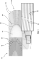
- Figure 1 shows a picture of a fragment of an angular sensor 10 according to an embodiment of this presentation, comprising a CVG resonator 12 having an 8-fold degree of rotational symmetry, comprising a flat central circular portion 14, the bottom of which (not shown) is attached to a substrate 16 by a support such as a pillar (not shown), as well as a plurality of concentric rings 18 in essentially the same plane as the circular portion 14.
- Each further concentric ring toward the outside of the resonator is attached to the preceding concentric ring by a series of N posts rotated 360/N degrees around the axis of the resonator with respect to the posts attaching the preceding ring to the center of the resonator.
- a multiple number of N of posts can also be used instead of N posts.
- the central portion 14, the concentric rings 18 and the posts 20 can be formed by etching away matter from a single substrate; for example a semiconductor substrate.
- Other types of resonator architectures than the one illustrated in Figure 1 can be used.
- a resonator of the type illustrated in Figure 1 is for example described in provisional US application No.
- the mechanical resonator 12 can be fabricated using standard microelectromechanical systems (MEMS) processes, especially high aspect ratio deep reactive ion etching (DRIE) of silicon-on-insulator (SOI) wafers and releasing the CVG mechanical resonator structure from the handle substrate via hydrofluoric (HF) acid etching (either liquid HF followed by critical point drying (CPD) or dry vapor HF release which doesn't require the subsequent CPD step).
- MEMS microelectromechanical systems
- DRIE deep reactive ion etching
- SOI silicon-on-insulator
- HF hydrofluoric acid etching
- CPD critical point drying
- An example of such a structure includes Disk Resonator Gyroscopes (DRGs, Figure 1 ) and Flower-of-life Vibratory Gyroscopes described in US Provisional Patent Application 62/542,744 ,
- a plurality of electrodes 22 are arranged on substrate 16 along the periphery of resonator 12, at a predetermined distance from the periphery of the resonator so as to form an electrostatic gap between the electrodes and the resonator.
- electrodes 22 can be separated from the periphery of the CVG mechanical resonator disk by a radial electrostatic gap ranging from 100 nm to 30 ⁇ m in width/distance; preferably 2 ⁇ m to 30 ⁇ m in distance.
- the electrodes 22 can be created by simultaneously etching a gap into the same (e.g. silicon) layer as the mechanical vibratory structure 12, so that the electrodes are self-aligned around the periphery of resonator 12.
- electrodes 22 comprise: a drive electrode and a sense electrode aligned along the anti-nodal axis of each of the first and second normal modes; a drive electrode and a sense electrode aligned along a first anti-nodal axis of each of the third and fourth normal modes mode; and a pair of bias tune electrodes aligned with at least one second anti-nodal axis of the third and fourth modes axis.
- the anti-nodal axis of a first of the four modes can be aligned with the anti-nodal axis of a second one of the four modes.
- a sensor according to the present disclosure comprises in priority drive and sense electrodes aligned with an anti-nodal axis of each of the first and second one of the four modes, over having a pair of bias tune electrodes aligned with an anti-nodal axis of one of said first and second modes. It is only when an anti-nodal axis of one of the first and second modes is free of drive and sense electrodes that it can comprise a pair of bias tune electrodes.
- each of the electrodes outlined above can be a differential electrode comprising at least two electrodes arranged side by side.
- the sensor can be sealed with a lid in a vacuum environment to maintain high quality factor (Q).
- FIG. 2 illustrates schematically elements of a sensing circuit 24 of an angular sensor 10 according to an embodiment of this presentation, the sensing circuit 24 comprising a coarse readout circuit 26, a fine readout circuit 28 and a summing circuit 30 generating a high dynamic range signal at an output 32.
- Sensing circuit 24 can be made, and can operate, as detailed for example in US patent application No. 15/253,694 .
- coarse readout circuit 26 and fine readout circuit 28 are coupled 26', 28' to the resonator electrodes to drive (with the drive electrodes) the first and second pairs of modes; measure (with the sense electrodes) motion of the first and second pairs of modes, and derive coarse and fine measurements of the rotation of the vibrating resonator 12 around its axis, as detailed hereafter.
- FIG. 3 illustrates the operation of sensing circuit 24 according to an embodiment of this presentation: coarse readout circuit 26 receives an analog angular rotation rate signal 262 (the rate at which resonator 12 rotates around its axis) and outputs a digital angular rotation rate signal 261 with a relatively small scale factor. Curve 261 shows a digital output of the coarse readout circuit 26 as a function of the analog rotation rate 262 of resonator 12.
- the coarse readout circuit 26 may generate a 19-bit data stream, each 19-bit number in the data stream output by coarse readout circuit 26 representing the instantaneous angular rate of the CVG 10, with a proportionality factor or "scale factor" equal to 2 18 (the 19th bit being a sign bit) divided by the maximum measurable rate.
- the scale factor may be 262,144/900 or about 291.3 bits per degrees per second and the rate resolution is 900/262,144 or about 0.0034 degrees per second.
- the coarse readout circuit can include 24-bit analog-to-digital and digital-to-analog converters (not shown), which may have inherent noise, so that the effective number of bits may be 19 or 20 bits.
- FIG. 3 illustrates a lower resolution, 4-bit ADC for clarity, where 16 ADC output levels corresponding to the possible 4-bit numbers are discernible on digital curve 261.
- the output of the coarse readout circuit 26 is fed 27 to the fine readout circuit 28 as an offset or bias adjustment, such that the output range of the fine readout circuit 28 can be significantly smaller, and a larger scale factor may be used.
- a residual angular rate measured by the fine readout circuit 28 may be ⁇ 0.003412 degrees per second, i.e., ⁇ 0.0017 degrees per second.
- the scale factor of the fine readout circuit 28 may be selected to be significantly greater than the scale factor of the coarse readout circuit 26.
- the fine readout circuit 28 also generates a 19-bit data stream, each 19-bit number in the data stream representing a residual instantaneous angular rate of the CVG (i.e. after subtraction of the coarse readout circuit offset)
- the resolution of the fine readout circuit 28 may be 0.0017 degrees per second divided by 2 18 (the 19th bit being a sign bit), i.e., 6.5 ⁇ 10 -9 degrees per second, or 24 microdegrees per hour.
- curve 281 shows the output of the fine readout circuit 28 without offset subtraction
- curve 282 shows the output of the fine readout circuit 28 with offset subtraction.
- fine readout circuit 28 can be configured to drive the third normal mode at a first drive frequency and to drive the fourth normal mode at a second drive frequency; and to derive a measurement of the difference between the true angular rate of the CVG resonator 12 and the coarse measurement 27 by adjusting the first drive frequency and the second drive frequency so that the difference between the first drive frequency and the second drive frequency is proportional to the coarse measurement 27.
- the drive frequency and phase of a mode can be determined by the signals sent to the drive electrode of the mode.
- fine readout circuit 28 can be configured to derive a measurement of the difference between the true angular rate of the CVG resonator 12 and the coarse measurement 27 by adjusting a natural frequency of the third normal mode and a natural frequency of the fourth normal mode so that the difference between the natural frequency of the third normal mode and the natural frequency of the fourth normal mode is proportional to the coarse measurement.
- a first pair (e.g. BT1) of bias tune electrodes can be used to adjust the third normal mode frequency; and a second pair (e.g. BT2) of bias tune electrodes can be used to adjust the fourth normal mode frequency
- Figure 4A shows a schematic of a drive circuit 34 of coarse readout circuit 26 according to embodiments of this presentation, comprising a first frequency reference 36 configured to generate a first reference signal 38; a first phase control circuit 40 configured to: measure a first phase difference between a first phase target, and the difference between a phase of an oscillation of the first normal mode 42 and a phase of the first reference signal 38; and to apply a first phase correction signal to the CVG resonator 12, to reduce the first phase difference.
- coarse readout circuit 26 further comprises a second phase control circuit 44 configured to measure a second phase difference between a second phase target, and the difference between a phase of an oscillation of the second normal mode 46 and the phase of the first reference signal 38; and to apply a second phase correction signal to the CVG resonator 12, to reduce the second phase difference.
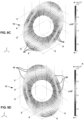
- Detailed diagrams illustrating the first and second normal modes can be found in Figures 9A and 9B .
- the first phase control circuit 40 can be configured to apply a first phase correction signal to the CVG resonator 12 by adjusting a natural frequency of the first normal mode.
- electrodes 22 do not comprise a dedicated DC tuning electrode for the first normal mode and a DC tuning voltage of the first normal mode is applied in addition to the AC voltage and/or current on the drive (e.g. N1D1 ⁇ +/- ⁇ ) and the sense (e.g. N1S1 ⁇ +/- ⁇ ) electrodes of the first normal mode to adjust the first normal mode frequency.
- the first phase control circuit 40 can be configured to adjust the natural frequency of the first normal mode by applying a bias voltage to a first tuning electrode of the CVG resonator 12.
- the natural frequency of the first normal mode can be adjusted by adding a DC tuning voltage to the AC signals on the drive (e.g. N1D1 ⁇ +/- ⁇ ) and the sense (e.g. N1S1 ⁇ +/- ⁇ ) electrodes of the first normal mode.
- the first phase control circuit 40 can be configured to adjust a natural frequency of the second normal mode by applying a bias voltage to a second tuning electrode of the CVG resonator.
- the frequency of the second normal mode can be adjusted by adding a DC tuning voltage to the AC signals on the drive (e.g. N1D2 ⁇ +/- ⁇ ) and the sense (e.g. N1S2 ⁇ +/- ⁇ ) electrodes of the second mode.
- Figure 4B shows a schematic of a drive circuit 48 of fine readout circuit 28 according to embodiments of this presentation, comprising a second frequency reference 50 configured to generate a second reference signal 52; a third phase control circuit 54 configured to: measure a third phase difference between a third phase target, and the difference between a phase of an oscillation of the third normal mode 56 and a phase of the second reference signal 52; and to apply a third phase correction signal to the CVG resonator 12, to reduce the third phase difference.
- fine readout circuit 48 further comprises a fourth phase control circuit 58 configured to measure a fourth phase difference between a fourth phase target, and the difference between a phase of an oscillation of the fourth normal mode 60 and the phase of the second reference signal 52; and to apply a fourth phase correction signal to the CVG resonator 12, to reduce the second phase difference.
- Detailed diagrams illustrating the third and fourth normal modes can be found in Figures 9C and 9D .
- drive circuits 34 and 48 are shown in two separate figures 4A and 4B , but the electrodes and components forming drive circuits 34 and 48 are preferably all arranged on substrate 16, as well as the remainder of sensing circuit 24.
- Drive circuits 34 and 48 can be made, and can operate, as detailed for example in US patent application No. 15/253,694 or in US patent application 15/253,704 .
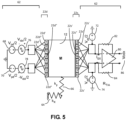
- Figure 5 illustrates differential electrodes 22d, 22s and a differential electrode drive and sense circuit 62 that can be part of an angular sensor according to an embodiment of this presentation.
- the drive and sense differential electrodes and the drive and sense circuit can be part of each of control circuits 40, 44, 54 and 58, the drive and sense electrodes being aligned with the mode associated with the control circuit.
- resonator 12 is illustrated as a rectangle mass M suspended by a pair of effective mechanical springs Kx 64 and Ky 66.
- Ky 66 may be assumed in some cases to be infinite such that the vibrational motion of the mass 12 occurs only in a single degree-of-freedom (DOF) along the horizontal or X direction.
- DOE degree-of-freedom
- mass 12 is assumed to be electrically conductive and at an electric ground potential of 0 volts.
- the X axis is aligned with one of the four normal modes of resonator 12.
- the other modes of resonator 12 or the circular shape of resonator 12 are not shown.
- a single drive electrode 22d is shown on one side of resonator 12 and a corresponding single sense electrode 22s is shown in the other side of resonator 12, aligned with electrode 22d along the X axis/normal mode of the resonator.
- drive electrode 22d and sense electrode 22s comprise each a sub-electrode set having at least one pair of differential sub-electrodes (respectively 22d', 22d" and 22s', 22s") arranged side by side.
- electrodes 22d, 22s comprise each more than one pair of differential sub-electrodes arranged side by side in an interdigitated manner.
- a first half 22d' of the sub-electrode set of drive electrode 22d can be maintained at a DC voltage 68 of -Vpd/2
- the second half 22d" of the sub-electrode set of drive electrode 22d can be maintained at a DC voltage 70 of -Vpd/2 so that a total potential difference between drive sub-electrodes 22d' and drive sub-electrode 22d" is Vpd.
- a first half 22s' of the sub-electrode set of sense electrode 22s can be maintained at a DC voltage 72 of +Vps/2, and the second half 22s" of the sub-electrode set of sense electrode 22s can be maintained at a DC voltage 74 of -Vps/2 so that a total potential difference between sense sub-electrodes 22s' and sense sub-electrode 22s" is Vps.
- the input driving voltage is split into out of phase halves, for example such that an AC voltage 76 of value Vid/2 applied to drive sub-electrodes 22d' is positive while an AC voltage 78 of value -Vid/2 applied to drive sub-electrodes 22d" is negative.
- This combination of out of phase electrical voltages is termed differential drive.
- the motional currents from sense sub-electrodes 22s', 22s", respectively, are out of phase for a uniform motion of mass 12. This is an example of differential sense.
- differential TIA 80 has a feedback resistor (R_TIA) 82 coupled to the negative input of TIA 80 and a feedback resistor (R_TIA) 84 coupled to the positive input of TIA 80.
- R_TIA feedback resistor
- R_TIA feedback resistor
- the TIA 80 amplifies the differential motional currents Isx from 22s" and 22s' and converts them to a differential output voltage Vodx 86.
- the device can also operate if the first sense sub-electrodes 22s" have a DC voltage of +Vps/2, and the second sense sub-electrodes 22s' have a DC voltage of -Vps/2. The total potential difference between the sense sub-electrodes 22s" and sense sub-electrodes 22s' is still Vps.
- the drive electrodes 22d', 22d" are driven by AC voltages Vid/2 (76) and -Vid/2 (78), which are 180 degrees out of phase, and because the parasitic capacitances, between drive sub-electrodes 22'd and sense sub-electrodes 22s" and between drive sub-electrodes 22d” and sense sub-electrodes 22s", are arranged to be approximately equal, the feedthrough currents generated by the parasitic capacitances are out of phase and cancel each other out at sense sub-electrodes 22s". Similarly, the out of phase feedthrough currents generated by the parasitic capacitances cancel each other out at sense sub-electrodes 22s'.
- differential electrodes 22d, 22s and differential electrode drive and sense circuit 62 illustrated in Figure 5 can for example be made, and can operate, as detailed in US patent application No. 14/836,462 .
- Figure 6 illustrates a portion of the node and anti-nodal axes of a CVG resonator 12 of an angular sensor according to an embodiment of this presentation.
- a drive electrode 22d (not shown) such as illustrated in Figure 5 is arranged on one side of the periphery of resonator 12 at the position marked D1, in alignment with axis 90; and a sense electrode 22s (not shown) such as illustrated in Figure 5 is arranged on the opposite side of the periphery of resonator 12 at the position marked S1, in alignment with axis 90.
- a drive electrode 22d (not shown) is arranged on one side of the periphery of resonator 12 at the position marked D2, in alignment with axis 92; and a sense electrode 22s (not shown) is arranged on the opposite side of the periphery of resonator 12 at the position marked S2, in alignment with axis 92.
- a bias tune electrode (not shown) is arranged on each side of the periphery of resonator 12 along axis 94 (at the positions marked BT1) because no anti-nodal axis of another mode of resonator 12 having sense/drive electrodes is aligned with axis 94.
- the bias tune electrodes can have the same structure as the sense and drive electrodes illustrated in figure 5 .
- a DC voltage can be maintained between the bias tune electrodes arranged along the anti-nodal axis of a mode to fine-tune the oscillation frequency of said mode (by making the electromechanical system of the resonator more or less rigid along said mode: applying an electrostatic tuning potential to the bias tune electrodes creates a negative electrostatic stiffness, resulting in a softer mode vibrational stiffness and effectively lowering the frequency of the mode).
- Such frequency tuning by adjusting a bias voltage can be implemented for example as detailed in US patent application No. 15/253,694 or in US patent application 15/253,704 .
- a DC voltage can be additionally sent to the drive electrodes of the sensor to add a linear component to the drive signal sent to the resonator; Similarly, a DC voltage can be additionally sent to the sense electrodes of the sensor to add a gain factor to the sense signal received on these electrodes.
- a bias tune electrode (not shown) is arranged on each side of the periphery of resonator 12 along axis 96, at the positions marked BT2.
- the bias tune electrodes at BT2 can have the same structure and the same function/operation with respect to the second mode as the bias tune electrodes at BT1 with respect to the first mode.
- a bias quadrature electrode (not shown) is arranged on each side of the periphery of resonator 12 along axis 98, at the positions marked BX1.
- a bias quadrature electrode (not shown) is arranged on each side of the periphery of resonator 12 along axis 100, at the positions also marked BX1.
- the bias quadrature electrodes at BX1 can have the same structure as the sense and drive electrodes illustrated in figure 5 . Dynamic control of DC voltages applied where appropriate to the bias quadrature electrodes at BX1 introduces a dynamically induced static torque that allows compensating for fabrication imperfections of the resonator 12. Having four electrodes at the four positions marked BX1 is preferred.
- bias quadrature axis are aligned with axis having sense and drive electrodes or bias tune electrodes of other modes, only two electrodes can be used to implement a partial bias quadrature control. Details about how to operate the BX1 electrodes and BX2 electrodes are provided hereafter in relation with Figure 7 .
- a bias quadrature electrode (not shown) is arranged on each side of the periphery of resonator 12 along axis 102, at the positions marked BX2.
- a bias quadrature electrode (not shown) is arranged on each side of the periphery of resonator 12 along axis 104, at the positions also marked BX2.
- the bias quadrature electrodes at BX2 can have the same structure as the sense and drive electrodes illustrated in figure 5 . Operation of the bias quadrature electrodes at BX2 can be the same as the operation of the bias quadrature electrodes at BX1.
- the drive electrode at position D1 can comprise two drive sub-electrodes 22', 22" respectively at positions D1+, D1-arranged symmetrically with respect to axis 90 on the periphery of resonator 12.
- the sense electrode at position S1 can comprise two sense sub-electrodes 22', 22" respectively at positions S1+, S1- arranged symmetrically with respect to axis 90 on the periphery of resonator 12, opposite position D1.
- the differential drive and sense electrodes at positions D1+, D1-; S1+, S1- can be connected to a first drive and sense circuit 62 such as illustrated in Figure 5 .
- the drive electrode 22 at position D2 can comprise two sense sub-electrodes 22', 22" respectively at positions D2+, D2- arranged symmetrically with respect to axis 92 on the periphery of resonator 12
- the sense electrode 22 at position S2 can comprise two sense sub-electrodes 22', 22" respectively at positions S2+, S2- arranged symmetrically with respect to axis 92 on the periphery of resonator 12, opposite position D2.
- the differential drive and sense electrodes at positions D2+, D2-; S2+, S2- can be connected to a second drive and sense circuit 62 such as illustrated in Figure 5 .
- the electrodes 22 at positions BT1, BT2, BX1 and BX2 can each comprise two sub-electrodes 22', 22" arranged symmetrically with respect to axis 94, 96, 98, 100, 102, 104 on each side of the periphery of resonator 12.
- the two sub-electrodes at each of positions BT1, BT2, BX1 and BX2 can be connected together, thus forming each a non-differential electrode.
- a ring electrode 106 can be arranged around the electrodes 22 of the sensor.
- contact pads 108 can be arranged on the surface of substrate 16, for example close to the edges of substrate 16 as illustrated in Figure 7 so as to form a LCC44-type package.
- substrate 16 can comprise at least one contact pad 108 corresponding to, and electrically connected with, each electrode 22 or sub-electrode 22', 22" of the sensor.
- each contact pad provided for receiving a signal can be separated from a neighboring contact pad provided for receiving another signal by a contact pad provided for being connected to a ground, coupled to the ring electrode 106 or also for example to the resonator 12 (GB pad).
- electrostatic transducer which may serve two purposes:
- TIA transimpedance amplifier
- ADC analog-to-digital converter
- a DC voltage must be applied across the electrostatic gap to polarize it, so that either the driving function or the sensing function of the particular electrostatic transducer can be performed.
- the drive and sense electrodes are split into positive (+) and negative (-) sub-electrodes, respectively.
- the vibratory motion can then be detected by applying a DC polarization voltage across the S1+ and S1- electrostatic transduction gaps. This in turn creates a pair of differential sense currents which are amplified and converted to a differential voltage signal by a differential TIA. The same method is applied to D2+/- and S2+/-.
- the BX1 electrodes if there is a substantial potential difference between them and electrodes GB, exert a counter clockwise (CCW) directed force on the two anti-nodal points on axis 90, which acts to pull the vibration mode pattern toward the BX1 electrodes.
- CCW counter clockwise
- the vibration pattern causes the effective gap to be larger (the disk is moving toward the center at these points), these points will experience a smaller force.
- the anti-nodal points on axis 94 go farther away from the center, and the anti-nodal points on axis 90 come closer to the center.
- AGC automatic gain control
- the sense mode motion in response to applied rotation will automatically be aligned since the Coriolis effect produces a force that is the cross product of the radially directed velocity and the vertically (out-of-plane) directed rotation axis.
- the direction of such a force is 45° from the drive axis, which is the sense mode.
- electrodes GB can be biased to a non-zero DC value and the BX1/BX2 electrodes can be nominally kept at DC ground (until a tuning potential is applied to them) or the GB electrodes can be held to ground potential and then BX1/BX2 can be DC biased.
- Figure 8 illustrates practical positions of the control and sense electrodes of a CVG resonator 12 of an angular sensor according to an embodiment of this presentation.
- a drive electrode for the first normal mode can comprise two drive sub-electrodes 22', 22" respectively at positions marked N1D1+, N2D1-, arranged symmetrically with respect to axis 110 on the periphery of resonator 12.
- a sense electrode for the first normal mode can comprise two sense sub-electrodes 22', 22" respectively at positions marked N1S1+, N1S1-, arranged symmetrically with respect to axis 110 on the periphery of resonator 12, opposite positions N1D1+, N1D1-.
- the differential drive and sense electrodes at positions N1D1+, N1D1-; N1S1+, NISI- can be connected to a third drive and sense circuit 62 such as illustrated in Figure 5 .
- a drive electrode for the second normal mode can comprise two drive sub-electrodes 22', 22" respectively at positions marked N1D2+, N1D2-, arranged symmetrically with respect to axis 112 on the periphery of resonator 12.
- a sense electrode for the second normal mode can comprise two sense sub-electrodes 22', 22" respectively at positions marked N1S2+, N1S2-, arranged symmetrically with respect to axis 112 on the periphery of resonator 12, opposite positions N1D2+, N1D2-.
- the differential drive and sense electrodes at positions N1D2+, N1D2-; N1S2+, N1S2- can be connected to a fourth drive and sense circuit 62 such as illustrated in Figure 5 .
- the sensor of Figure 8 comprises sense and drive sub-electrodes as disclosed in Figure 7 , at positions N2D1+, N2D1-, N2S1+, N2S1-, N2D2+, N2D2-, N2S2-+-, N2S2-- for driving and sensing oscillations along the normal modes having anti-nodal axes 90 and 92.
- the positions of the drive and sense electrodes for a mode can be exchanged to one side or another of the periphery of the resonator 12.
- no bias tune electrodes of the first or second normal modes is present on the periphery of resonator 12.
- a first pair of bias quadrature electrodes is arranged on the periphery of resonator 12, at positions BX2 aligned with axis 100, which is 45 degrees off axis 110; and a second pair of bias quadrature electrodes is arranged on the periphery of resonator 12, at positions BX1 aligned with axis 98, which is 45 degrees off axis 112.
- each bias quadrature electrode at positions BX1, BX2 is illustrated in Figure 8 as comprising two sub-electrodes arranged symmetrically with respect to axis 98, 100.
- the two sub-electrodes of each bias quadrature electrode can be connected together to a contact pad on substrate 16; and alternatively each bias quadrature electrode can be a single electrode.
- normal mode of resonator 12 (along axis 90) comprises no drive/sense electrodes from another mode of resonator 12, a pair of bias tune electrodes of the third normal mode is present at positions BT1 on the periphery of resonator 12, aligned with axis 94.
- normal mode of resonator 12 (along axis 92) comprises no drive/sense electrodes from another mode of resonator 12, a pair of bias tune electrodes of the fourth normal mode is present at positions BT2 on the periphery of resonator 12, aligned with axis 96.
- the contact pads coupled to differential sub-electrodes can be arranged side by side on substrate 16, for example as illustrated in Figure 8 .
- amplitude of the deformations of resonator 12 are exaggerated in the figures for clarity; the maximum amplitude of the resonator being smaller than the distance between the periphery of the resonator and the electrodes of the sensor when the resonator is at rest.
- This presentation discloses applying multi-mode control of the type disclosed in US application No.
- Figures 11A and 11B illustrate how the oscillation frequencies of the modes of a pair of modes can be controlled according to an embodiment of this presentation.
- FIG. 11B illustrates the output voltage signal from the angular sensor when it is operated using the control loops as illustrated in Figure 4 .
- a known sinusoidal physical rotation with a period of 8 seconds was applied to the angular sensor using a precision rate table and the resulting output voltage proportional to the rotation rate was measured.
Landscapes
- Physics & Mathematics (AREA)
- Engineering & Computer Science (AREA)
- General Physics & Mathematics (AREA)
- Radar, Positioning & Navigation (AREA)
- Remote Sensing (AREA)
- Gyroscopes (AREA)
Claims (20)
- Winkelsensor, der folgendes umfasst:einen Coriolis-Vibrationsgyroskopresonator (12), der entlang folgendem oszillieren kann: einem ersten Paar normaler n = 1 Modi (42, 46), umfassend einen ersten Normalmodus (42) und einen zweiten Normalmodus (46); wobei der erste und der zweite Normalmodus jeweils eine Antiknotenachse (100, 98) aufweisen; undeinem zweiten Paar normaler n = 2 Modi (56, 60), umfassend einen dritten Normalmodus (60) und einen vierten Normalmodus (56); wobei der dritte und der vierte Normalmodus (56, 60) jeweils zwei Antiknotenachsen (92, 96; 94, 90) aufweisen;einer Steuerelektrode (22d) und einer Messelektrode (22s), die ausgerichtet sind entlang der Antiknotenachse (100, 98) jedes ersten und zweiten Normalmodus (42, 46);einer Steuerelektrode (22d) und einer Messelektrode (22s), die ausgerichtet sind entlang einer ersten Antiknotenachse (92, 96; 94, 90) jedes dritten und vierten Normalmodus; undeines Paars von Vorspannungsabstimmungselektroden, die ausgerichtet sind mit einer zweiten Antiknotenachse (92, 96; 94, 90) des dritten oder des vierten Normalmodus;wobei der Winkelsensor keine mit der zweiten Antiknotenachse ausgerichtete Steuer- oder Messelektrode umfasst.
- Winkelsensor nach Anspruch 1, wobei kein Paar von Steuerelektroden, Messelektroden und Vorspannungsabstimmungselektroden entlang einer ersten Vorspannungsquadraturachse (98, 100; 102, 104) angeordnet ist, wobei die erste Vorspannungsquadraturachse um 360/(8*n) Grad von einer der Antiknotenachsen (92, 96; 94, 90) der normalen n = 1 und n = 2 Modi versetzt ist, die mindestens eine Mess-(22s) oder Steuerelektrode (22d) aufweist,
wobei der Winkelsensor ferner folgendes umfasst:
ein erstes Paar von Vorspannungsquadraturelektroden, die entlang der ersten Vorspannungsquadraturachse ausgerichtet sind. - Winkelsensor nach Anspruch 1, wobei kein Paar von Steuerelektroden, Messelektroden und Vorspannungsabstimmungselektroden entlang einer zweiten Vorspannungsquadraturachse (98, 100; 102, 104) angeordnet ist, wobei die zweite Vorspannungsquadraturachse um 360/(8*n) Grad von mindestens einer zweiten Antiknotenachse des dritten und vierten normalen n=2 Modus versetzt ist, der das Paar von Vorspannungsabstimmungselektroden aufweist,
wobei der Winkelsensor ferner ein zweites Paar von Vorspannungsquadraturelektroden umfasst, die mit der zweiten Vorspannungsquadraturachse ausgerichtet sind. - Winkelsensor nach Anspruch 1, der folgendes umfasst:
einen groben Auslesekreis (26), der für folgende Zwecke gestaltet ist:Steuern des ersten Normalmoduspaares (42, 46),Messen der Bewegung des ersten Normalmoduspaares (42, 46) mit einer ersten Empfindlichkeit, und Ableiten von der gemessenen Bewegung des ersten Normalmoduspaares (42, 46) einer groben Messung einer realen Winkelgeschwindigkeit des Coriolis-Vibrationsgyroskopresonators (12), undeinen feinen Auslesekreis (28), der für folgende Zwecke gestaltet ist:Empfangen der groben Messung,Steuern des zweiten Normalmoduspaares (56, 60),Messen der Bewegung des zweiten Normalmoduspaares (60, 56) mit einer zweiten Empfindlichkeit, die höher ist als die erste Empfindlichkeit, wobei die Messung durch die grobe Messung ausgeglichen wird; undvon der gemessenen Bewegung des zweiten Normalmoduspaares (56, 60) und der empfangenen groben Messung, Ableiten einer feinen Messung der realen Winkelgeschwindigkeit des Coriolis-Vibrationsgyroskopresonators (12). - Winkelsensor nach Anspruch 4, wobei der grobe Auslesekreis (26) zum Steuern des ersten Normalmoduspaares (42, 46) folgendes umfasst:
einen ersten Frequenzbezugswert (36), der so gestaltet ist, dass er ein erstes Referenzsignal (38) erzeugt; und einen ersten Phasenregelkreis (40), der für folgende Zwecke gestaltet ist:Messen einer ersten Phasendifferenz zwischen einem ersten Phasenziel und der Differenz zwischen: einer Phase einer Oszillation des ersten Normalmodus (42) und einer Phase des ersten Referenzsignals (38);Zuführen eines ersten Phasenkorrektursignals an den Coriolis-Vibrationsgyroskopresonator (12), um die erste Phasendifferenz zu reduzieren; undeinen zweiten Phasenregelkreis (44), der für folgende Zwecke gestaltet ist:Messen einer zweiten Phasendifferenz zwischen einem zweiten Phasenziel und der Differenz zwischen: einer Phase einer Oszillation des zweiten Normalmodus (46) und der Phase des ersten Referenzsignals (38); undZuführen eines zweiten Phasenkorrektursignals an den Coriolis-Vibrationsgyroskopresonator (12), um die zweite Phasendifferenz zu reduzieren. - Winkelsensor nach Anspruch 5, wobei der feine Auslesekreis (28) zum Steuern des zweiten Normalmoduspaares (56, 60) folgendes umfasst:einen zweiten Frequenzbezugswert (50), der zum Erzeugen eines zweiten Referenzsignals (52) gestaltet ist;einen dritten Phasenregelkreis (54), der für folgende Zwecke gestaltet ist:Messen einer dritten Phasendifferenz zwischen einem dritten Phasenziel und der Differenz zwischen: einer Phase der Oszillation des dritten Normalmodus (56) und einer Phase des zweiten Referenzsignals (52); undZuführen eines dritten Phasenkorrektursignals an den Coriolis-Vibrationsgyroskopresonator (12), um die dritte Phasendifferenz zu reduzieren; undeinen vierten Phasenregelkreis (58), der für folgende Zwecke gestaltet ist:
Messen einer vierten Phasendifferenz zwischen einem vierten Phasenziel und der Differenz zwischen: einer Phase der Oszillation des vierten Normalmodus (60) und der Phase des zweiten Referenzsignals (52); und Zuführen eines vierten Phasenkorrektursignals an den Coriolis-Vibrationsgyroskopresonator (12), um die vierte Phasendifferenz zu reduzieren. - Winkelsensor nach Anspruch 4, wobei der feine Auslesekreis (28) so gestaltet ist, dass er den dritten Normalmodus (56) mit einer ersten Steuerfrequenz steuert und den vierten Normalmodus (60) mit einer zweiten Steuerfrequenz steuert, und
wobei der feine Auslesekreis (28) so gestaltet ist, dass er die feine Messung der realen Winkelgeschwindigkeit des Coriolis-Vibrationsgyroskopresonators (12) ableitet durch Anpassung der ersten Steuerfrequenz und der zweiten Steuerfrequenz, so dass die Differenz zwischen der ersten Steuerfrequenz und der zweiten Steuerfrequenz proportional zu der groben Messung ist. - Winkelsensor nach Anspruch 4, wobei der feine Auslesekreis (28) so gestaltet ist, dass er die feine Messung der realen Winkelgeschwindigkeit des Coriolis-Vibrationsgyroskopresonators (12) ableitet durch Anpassung einer natürlichen Frequenz des dritten Normalmodus (56) und einer natürlichen Frequenz des vierten Normalmodus (60), so dass die Differenz zwischen der natürlichen Frequenz des dritten Normalmodus (56) und der natürlichen Frequenz des vierten Normalmodus (60) proportional zu der groben Messung ist.
- Winkelsensor nach Anspruch 1, wobei der Resonator (12) eine N-fache Rotationssymmetrie aufweist, wobei N eine Zweierpotenz und mindestens gleich 8 ist.
- Winkelsensor nach Anspruch 1, wobei jede Elektrode (22) eine Unterelektrodengruppe mit mindestens einem Paar differentieller Unterelektroden (22', 22") umfasst.
- Winkelsensor nach Anspruch 10, der mindestens 32 Unterelektroden (22', 22") umfasst.
- Winkelsensor nach Anspruch 10, wobei die zwei Unterelektroden (22', 22") jedes Unterelektrodenpaares angeordnet sind für den Empfang oder das Senden differentieller Signale mit einer Phasenverschiebung von 180 Grad zueinander.
- Winkelsensor nach Anspruch 5, wobei der erste Phasenregelkreis so gestaltet ist, dass er dem Coriolis-Vibrationsgyroskopresonator (12) ein erstes Phasenkorrektursignal zuführt durch Anpassung einer natürlichen Frequenz des ersten Normalmodus (40).
- Winkelsensor nach Anspruch 5, wobei der erste Phasenregelkreis so gestaltet ist, dass er die natürliche Frequenz des ersten Normalmodus (40) anpasst durch Zufuhr einer Vorspannungsspannung an eine erste Abstimmungselektrode des Coriolis-Vibrationsgyroskopresonators (12).
- Winkelsensor nach Anspruch 5, wobei der zweite Phasenregelkreis (44) so gestaltet ist, dass er eine natürliche Frequenz des zweiten Normalmodus (46) anpasst durch Zufuhr einer Vorspannungsspannung an eine zweite Abstimmungselektrode des Coriolis-Vibrationsgyroskopresonators (12).
- Winkelsensor nach Anspruch 4, wobei der grobe Auslesekreis (26) so gestaltet ist, dass er das erste Moduspaar (42, 46) so steuert, dass sich eine Phase der Bewegung des ersten Normalmodus (42) um 90 Grad von einer Phase der Bewegung des zweiten Normalmodus (46) unterscheidet.
- Winkelsensor nach Anspruch 4, wobei der feine Auslesekreis (28) so gestaltet ist, dass er das zweite Moduspaar (56, 60) so steuert, dass eine Amplitude der Bewegung des dritten Normalmodus (56) das Zehnfache einer Amplitude der Bewegung des vierten Normalmodus (60) entspricht.
- Winkelsensor nach Anspruch 4, wobei der feine Auslesekreis (28) so gestaltet ist, dass er das zweite Moduspaar (56, 60) so steuert, dass sich eine Phase der Bewegung des dritten Normalmodus (56) um 90 Grad von einer Phase der Bewegung des vierten Normalmodus (60) unterscheidet.
- Winkelsensor nach Anspruch 4, wobei der feine Auslesekreis (28) so gestaltet ist, dass er den dritten Normalmodus (56) mit einer ersten Steuerfrequenz steuert und den vierten Normalmodus (60) mit einer zweiten Steuerfrequenz steuert, und wobei der feine Auslesekreis (28) so gestaltet ist, dass er eine Messung der Differenz zwischen der realen Winkelgeschwindigkeit des Coriolis-Vibrationsgyroskopresonators (12) und der groben Messung ableitet durch Anpassung der ersten Steuerfrequenz und der zweiten Steuerfrequenz, so dass die Differenz zwischen der ersten Steuerfrequenz und der zweiten Steuerfrequenz proportional zu der groben Messung ist.
- Winkelsensor nach Anspruch 4, wobei der feine Auslesekreis (28) so gestaltet ist, dass er eine Messung der Differenz zwischen der realen Winkelgeschwindigkeit des Coriolis-Vibrationsgyroskopresonators (12) und der groben Messung ableitet durch Anpassung einer natürlichen Frequenz des dritten Normalmodus (56) und einer natürlichen Frequenz des vierten Normalmodus (60), so dass die Differenz zwischen der natürlichen Frequenz des dritten Normalmodus (56) und der natürlichen Frequenz des vierten Normalmodus (60) proportional zu der groben Messung ist.
Applications Claiming Priority (2)
| Application Number | Priority Date | Filing Date | Title |
|---|---|---|---|
| US201762544661P | 2017-08-11 | 2017-08-11 | |
| PCT/US2018/036786 WO2019032179A1 (en) | 2017-08-11 | 2018-06-08 | SILICON MULTI-MODE CORIOLIS VIBRATORY GYROSCOPES HAVING A HIGH-RODING SYMMETRIC MECHANICAL STRUCTURE AND 32 ELECTRODES |
Publications (3)
| Publication Number | Publication Date |
|---|---|
| EP3665436A1 EP3665436A1 (de) | 2020-06-17 |
| EP3665436A4 EP3665436A4 (de) | 2021-05-19 |
| EP3665436B1 true EP3665436B1 (de) | 2025-01-15 |
Family
ID=65272578
Family Applications (1)
| Application Number | Title | Priority Date | Filing Date |
|---|---|---|---|
| EP18844644.7A Active EP3665436B1 (de) | 2017-08-11 | 2018-06-08 | Silizium-multimoden-coriolis-vibrationskreisel mit rotationssymmetrischer mechanischer struktur hoher ordnung und 32 elektroden |
Country Status (4)
| Country | Link |
|---|---|
| US (1) | US10436587B2 (de) |
| EP (1) | EP3665436B1 (de) |
| CN (1) | CN111670338B (de) |
| WO (1) | WO2019032179A1 (de) |
Families Citing this family (4)
| Publication number | Priority date | Publication date | Assignee | Title |
|---|---|---|---|---|
| EP3721055B1 (de) | 2017-12-04 | 2023-04-26 | HRL Laboratories, LLC | Kontinuierliche bahnberechnung für richtungsbohren |
| CN111854722B (zh) * | 2020-07-30 | 2022-05-10 | 中国人民解放军国防科技大学 | 曲折柔性环的嵌套环式微机电振动陀螺 |
| US11867509B2 (en) | 2021-03-03 | 2024-01-09 | Invensense, Inc. | Robust method for gyroscope drive amplitude measurement |
| US12607463B1 (en) * | 2022-06-08 | 2026-04-21 | Inertialwave, Inc. | Universal resonator controller |
Citations (1)
| Publication number | Priority date | Publication date | Assignee | Title |
|---|---|---|---|---|
| US20080148846A1 (en) * | 2006-12-22 | 2008-06-26 | The Boeing Company | Vibratory gyroscope with parasitic mode damping |
Family Cites Families (16)
| Publication number | Priority date | Publication date | Assignee | Title |
|---|---|---|---|---|
| US7168318B2 (en) | 2002-08-12 | 2007-01-30 | California Institute Of Technology | Isolated planar mesogyroscope |
| UA79166C2 (en) * | 2005-05-31 | 2007-05-25 | Yurii Oleksiiovych Yatsenko | Detecting element of a vibratory gyroscope sensitive to coriolis acceleration |
| US8061201B2 (en) * | 2007-07-13 | 2011-11-22 | Georgia Tech Research Corporation | Readout method and electronic bandwidth control for a silicon in-plane tuning fork gyroscope |
| US8205495B2 (en) * | 2008-06-10 | 2012-06-26 | The Boeing Company | Systematic disc resonator gyroscope tuning |
| US8333112B2 (en) | 2008-06-10 | 2012-12-18 | The Boeing Company | Frequency tuning of disc resonator gyroscopes via resonator mass perturbation based on an identified model |
| US8011246B2 (en) * | 2008-09-22 | 2011-09-06 | Northrop Grumman Guidance And Electronics Company, Inc. | Apparatus and method for self-calibration of coriolis vibratory gyroscope |
| DE102010006584B4 (de) * | 2010-02-02 | 2012-09-27 | Northrop Grumman Litef Gmbh | Corioliskreisel mit Korrektureinheiten und Verfahren zur Reduktion des Quadraturbias |
| CN103348252B (zh) * | 2010-12-07 | 2016-01-20 | 佐治亚科技研究公司 | 模式匹配型单一质量块双轴陀螺仪及制造方法 |
| US9157739B1 (en) | 2012-08-07 | 2015-10-13 | Innalabs Limited | Force-rebalance coriolis vibratory gyroscope |
| US20140260611A1 (en) * | 2013-03-15 | 2014-09-18 | Analog Devices, Inc. | XY-Axis Gyroscopes with Electrode Configuration for Detecting Quadrature Errors and Out-of-Plane Sense Modes |
| WO2017075413A1 (en) * | 2015-10-28 | 2017-05-04 | Georgia Tech Research Corporation | Comb-driven substrate decoupled annulus pitch/roll baw gyroscope with slanted quadrature tuning electrode |
| JP6514790B2 (ja) * | 2016-01-27 | 2019-05-15 | 株式会社日立製作所 | ジャイロスコープ |
| SG11201806199YA (en) * | 2016-02-01 | 2018-08-30 | Agency Science Tech & Res | Gyroscope devices and methods for fabricating gyroscope devices |
| JP6689227B2 (ja) * | 2017-03-15 | 2020-04-28 | 株式会社日立製作所 | ジャイロスコープ |
| JP6627912B2 (ja) * | 2017-05-24 | 2020-01-08 | 株式会社村田製作所 | 圧電回転mems共振器 |
| JP6627911B2 (ja) * | 2017-05-24 | 2020-01-08 | 株式会社村田製作所 | 圧電回転mems共振器 |
-
2018
- 2018-06-08 WO PCT/US2018/036786 patent/WO2019032179A1/en not_active Ceased
- 2018-06-08 CN CN201880050670.0A patent/CN111670338B/zh active Active
- 2018-06-08 EP EP18844644.7A patent/EP3665436B1/de active Active
- 2018-06-08 US US16/004,310 patent/US10436587B2/en active Active
Patent Citations (1)
| Publication number | Priority date | Publication date | Assignee | Title |
|---|---|---|---|---|
| US20080148846A1 (en) * | 2006-12-22 | 2008-06-26 | The Boeing Company | Vibratory gyroscope with parasitic mode damping |
Also Published As
| Publication number | Publication date |
|---|---|
| EP3665436A4 (de) | 2021-05-19 |
| US20190049246A1 (en) | 2019-02-14 |
| CN111670338A (zh) | 2020-09-15 |
| CN111670338B (zh) | 2022-05-17 |
| WO2019032179A1 (en) | 2019-02-14 |
| US10436587B2 (en) | 2019-10-08 |
| WO2019032179A9 (en) | 2019-03-07 |
| EP3665436A1 (de) | 2020-06-17 |
Similar Documents
| Publication | Publication Date | Title |
|---|---|---|
| US9605964B2 (en) | Gyro quadrature stabalization with demodulation phase error nulling | |
| EP2191232B1 (de) | Verbesserungen in bezug auf winkelgeschwindigkeitssensoren | |
| US8061201B2 (en) | Readout method and electronic bandwidth control for a silicon in-plane tuning fork gyroscope | |
| Kline et al. | Quadrature FM gyroscope | |
| US9696340B2 (en) | Multi-axis chip-scale MEMS inertial measurement unit (IMU) based on frequency modulation | |
| Izyumin et al. | A 7ppm, 6/hr frequency-output MEMS gyroscope | |
| US8056413B2 (en) | Sensor and sensing method utilizing symmetrical differential readout | |
| US10209270B2 (en) | Inertial sensors | |
| EP3056859B1 (de) | Vorspannungs- und massstabfehlerabschwächung in einem coriolis-vibrationskreiselsystem | |
| US10436587B2 (en) | Multi-mode coriolis vibratory gyroscopes having high order rotationally symmetric mechanical structure and 32 electrodes | |
| WO2008072008A1 (en) | Improvements in or relating to a gyroscope | |
| JP2005521036A (ja) | マイクロ電子機械システム | |
| JPS6315528B2 (de) | ||
| JPH10160483A (ja) | レートセンサ | |
| JP6278604B2 (ja) | バイアス補正機能を備えた振動型ジャイロ | |
| JP6600672B2 (ja) | 半球共振型ジャイロスコープ | |
| Senkal et al. | Dual foucault pendulum gyroscope | |
| US11835339B1 (en) | Continuous online self-calibration for gyroscopes through modulation of damping axes | |
| US20140013845A1 (en) | Class ii coriolis vibratory rocking mode gyroscope with central fixed post | |
| Parajuli et al. | Silicon MEMS gyroscope with quatrefoil suspension system achieving 1 million quality factor | |
| EP2040032A1 (de) | Verbesserungen bei oder im Zusammenhang mit Winkelgeschwindigkeitssensoren | |
| Liu et al. | Digital closed-loop control based on adaptive filter for drive mode of a MEMS gyroscope | |
| Padovani et al. | In-plane and out-of-plane FM accelerometers with 130 DB dynamic range through nems-based oscillators | |
| Song et al. | Parametric drive of a micro rate integrating gyroscope using discrete electrodes | |
| Soderkvist | Micromachined vibrating gyroscopes |
Legal Events
| Date | Code | Title | Description |
|---|---|---|---|
| STAA | Information on the status of an ep patent application or granted ep patent |
Free format text: STATUS: THE INTERNATIONAL PUBLICATION HAS BEEN MADE |
|
| PUAI | Public reference made under article 153(3) epc to a published international application that has entered the european phase |
Free format text: ORIGINAL CODE: 0009012 |
|
| STAA | Information on the status of an ep patent application or granted ep patent |
Free format text: STATUS: REQUEST FOR EXAMINATION WAS MADE |
|
| 17P | Request for examination filed |
Effective date: 20200304 |
|
| AK | Designated contracting states |
Kind code of ref document: A1 Designated state(s): AL AT BE BG CH CY CZ DE DK EE ES FI FR GB GR HR HU IE IS IT LI LT LU LV MC MK MT NL NO PL PT RO RS SE SI SK SM TR |
|
| AX | Request for extension of the european patent |
Extension state: BA ME |
|
| DAV | Request for validation of the european patent (deleted) | ||
| DAX | Request for extension of the european patent (deleted) | ||
| A4 | Supplementary search report drawn up and despatched |
Effective date: 20210414 |
|
| RIC1 | Information provided on ipc code assigned before grant |
Ipc: G01C 19/56 20120101AFI20210409BHEP Ipc: G01C 25/00 20060101ALI20210409BHEP |
|
| STAA | Information on the status of an ep patent application or granted ep patent |
Free format text: STATUS: EXAMINATION IS IN PROGRESS |
|
| 17Q | First examination report despatched |
Effective date: 20230323 |
|
| GRAP | Despatch of communication of intention to grant a patent |
Free format text: ORIGINAL CODE: EPIDOSNIGR1 |
|
| STAA | Information on the status of an ep patent application or granted ep patent |
Free format text: STATUS: GRANT OF PATENT IS INTENDED |
|
| INTG | Intention to grant announced |
Effective date: 20240913 |
|
| GRAS | Grant fee paid |
Free format text: ORIGINAL CODE: EPIDOSNIGR3 |
|
| GRAA | (expected) grant |
Free format text: ORIGINAL CODE: 0009210 |
|
| STAA | Information on the status of an ep patent application or granted ep patent |
Free format text: STATUS: THE PATENT HAS BEEN GRANTED |
|
| P01 | Opt-out of the competence of the unified patent court (upc) registered |
Free format text: CASE NUMBER: APP_62488/2024 Effective date: 20241122 |
|
| AK | Designated contracting states |
Kind code of ref document: B1 Designated state(s): AL AT BE BG CH CY CZ DE DK EE ES FI FR GB GR HR HU IE IS IT LI LT LU LV MC MK MT NL NO PL PT RO RS SE SI SK SM TR |
|
| REG | Reference to a national code |
Ref country code: CH Ref legal event code: EP Ref country code: GB Ref legal event code: FG4D |
|
| REG | Reference to a national code |
Ref country code: DE Ref legal event code: R096 Ref document number: 602018078578 Country of ref document: DE |
|
| REG | Reference to a national code |
Ref country code: IE Ref legal event code: FG4D |
|
| REG | Reference to a national code |
Ref country code: NL Ref legal event code: MP Effective date: 20250115 |
|
| PG25 | Lapsed in a contracting state [announced via postgrant information from national office to epo] |
Ref country code: NL Free format text: LAPSE BECAUSE OF FAILURE TO SUBMIT A TRANSLATION OF THE DESCRIPTION OR TO PAY THE FEE WITHIN THE PRESCRIBED TIME-LIMIT Effective date: 20250115 |
|
| PG25 | Lapsed in a contracting state [announced via postgrant information from national office to epo] |
Ref country code: RS Free format text: LAPSE BECAUSE OF FAILURE TO SUBMIT A TRANSLATION OF THE DESCRIPTION OR TO PAY THE FEE WITHIN THE PRESCRIBED TIME-LIMIT Effective date: 20250415 |
|
| PG25 | Lapsed in a contracting state [announced via postgrant information from national office to epo] |
Ref country code: FI Free format text: LAPSE BECAUSE OF FAILURE TO SUBMIT A TRANSLATION OF THE DESCRIPTION OR TO PAY THE FEE WITHIN THE PRESCRIBED TIME-LIMIT Effective date: 20250115 |
|
| PG25 | Lapsed in a contracting state [announced via postgrant information from national office to epo] |
Ref country code: PL Free format text: LAPSE BECAUSE OF FAILURE TO SUBMIT A TRANSLATION OF THE DESCRIPTION OR TO PAY THE FEE WITHIN THE PRESCRIBED TIME-LIMIT Effective date: 20250115 |
|
| PGFP | Annual fee paid to national office [announced via postgrant information from national office to epo] |
Ref country code: DE Payment date: 20250627 Year of fee payment: 8 |
|
| PG25 | Lapsed in a contracting state [announced via postgrant information from national office to epo] |
Ref country code: ES Free format text: LAPSE BECAUSE OF FAILURE TO SUBMIT A TRANSLATION OF THE DESCRIPTION OR TO PAY THE FEE WITHIN THE PRESCRIBED TIME-LIMIT Effective date: 20250115 |
|
| REG | Reference to a national code |
Ref country code: LT Ref legal event code: MG9D |
|
| PG25 | Lapsed in a contracting state [announced via postgrant information from national office to epo] |
Ref country code: IS Free format text: LAPSE BECAUSE OF FAILURE TO SUBMIT A TRANSLATION OF THE DESCRIPTION OR TO PAY THE FEE WITHIN THE PRESCRIBED TIME-LIMIT Effective date: 20250515 Ref country code: NO Free format text: LAPSE BECAUSE OF FAILURE TO SUBMIT A TRANSLATION OF THE DESCRIPTION OR TO PAY THE FEE WITHIN THE PRESCRIBED TIME-LIMIT Effective date: 20250415 |
|
| REG | Reference to a national code |
Ref country code: AT Ref legal event code: MK05 Ref document number: 1760097 Country of ref document: AT Kind code of ref document: T Effective date: 20250115 |
|
| PG25 | Lapsed in a contracting state [announced via postgrant information from national office to epo] |
Ref country code: HR Free format text: LAPSE BECAUSE OF FAILURE TO SUBMIT A TRANSLATION OF THE DESCRIPTION OR TO PAY THE FEE WITHIN THE PRESCRIBED TIME-LIMIT Effective date: 20250115 |
|
| PG25 | Lapsed in a contracting state [announced via postgrant information from national office to epo] |
Ref country code: PT Free format text: LAPSE BECAUSE OF FAILURE TO SUBMIT A TRANSLATION OF THE DESCRIPTION OR TO PAY THE FEE WITHIN THE PRESCRIBED TIME-LIMIT Effective date: 20250515 Ref country code: LV Free format text: LAPSE BECAUSE OF FAILURE TO SUBMIT A TRANSLATION OF THE DESCRIPTION OR TO PAY THE FEE WITHIN THE PRESCRIBED TIME-LIMIT Effective date: 20250115 |
|
| PG25 | Lapsed in a contracting state [announced via postgrant information from national office to epo] |
Ref country code: BG Free format text: LAPSE BECAUSE OF FAILURE TO SUBMIT A TRANSLATION OF THE DESCRIPTION OR TO PAY THE FEE WITHIN THE PRESCRIBED TIME-LIMIT Effective date: 20250115 Ref country code: GR Free format text: LAPSE BECAUSE OF FAILURE TO SUBMIT A TRANSLATION OF THE DESCRIPTION OR TO PAY THE FEE WITHIN THE PRESCRIBED TIME-LIMIT Effective date: 20250416 |
|
| PG25 | Lapsed in a contracting state [announced via postgrant information from national office to epo] |
Ref country code: AT Free format text: LAPSE BECAUSE OF FAILURE TO SUBMIT A TRANSLATION OF THE DESCRIPTION OR TO PAY THE FEE WITHIN THE PRESCRIBED TIME-LIMIT Effective date: 20250115 |
|
| PG25 | Lapsed in a contracting state [announced via postgrant information from national office to epo] |
Ref country code: SE Free format text: LAPSE BECAUSE OF FAILURE TO SUBMIT A TRANSLATION OF THE DESCRIPTION OR TO PAY THE FEE WITHIN THE PRESCRIBED TIME-LIMIT Effective date: 20250115 |
|
| PG25 | Lapsed in a contracting state [announced via postgrant information from national office to epo] |
Ref country code: SM Free format text: LAPSE BECAUSE OF FAILURE TO SUBMIT A TRANSLATION OF THE DESCRIPTION OR TO PAY THE FEE WITHIN THE PRESCRIBED TIME-LIMIT Effective date: 20250115 |
|
| PG25 | Lapsed in a contracting state [announced via postgrant information from national office to epo] |
Ref country code: DK Free format text: LAPSE BECAUSE OF FAILURE TO SUBMIT A TRANSLATION OF THE DESCRIPTION OR TO PAY THE FEE WITHIN THE PRESCRIBED TIME-LIMIT Effective date: 20250115 |
|
| PG25 | Lapsed in a contracting state [announced via postgrant information from national office to epo] |
Ref country code: IT Free format text: LAPSE BECAUSE OF FAILURE TO SUBMIT A TRANSLATION OF THE DESCRIPTION OR TO PAY THE FEE WITHIN THE PRESCRIBED TIME-LIMIT Effective date: 20250115 |
|
| REG | Reference to a national code |
Ref country code: DE Ref legal event code: R097 Ref document number: 602018078578 Country of ref document: DE |
|
| PG25 | Lapsed in a contracting state [announced via postgrant information from national office to epo] |
Ref country code: CZ Free format text: LAPSE BECAUSE OF FAILURE TO SUBMIT A TRANSLATION OF THE DESCRIPTION OR TO PAY THE FEE WITHIN THE PRESCRIBED TIME-LIMIT Effective date: 20250115 Ref country code: EE Free format text: LAPSE BECAUSE OF FAILURE TO SUBMIT A TRANSLATION OF THE DESCRIPTION OR TO PAY THE FEE WITHIN THE PRESCRIBED TIME-LIMIT Effective date: 20250115 |
|
| PG25 | Lapsed in a contracting state [announced via postgrant information from national office to epo] |
Ref country code: RO Free format text: LAPSE BECAUSE OF FAILURE TO SUBMIT A TRANSLATION OF THE DESCRIPTION OR TO PAY THE FEE WITHIN THE PRESCRIBED TIME-LIMIT Effective date: 20250115 |
|
| PG25 | Lapsed in a contracting state [announced via postgrant information from national office to epo] |
Ref country code: SK Free format text: LAPSE BECAUSE OF FAILURE TO SUBMIT A TRANSLATION OF THE DESCRIPTION OR TO PAY THE FEE WITHIN THE PRESCRIBED TIME-LIMIT Effective date: 20250115 |
|
| PLBE | No opposition filed within time limit |
Free format text: ORIGINAL CODE: 0009261 |
|
| STAA | Information on the status of an ep patent application or granted ep patent |
Free format text: STATUS: NO OPPOSITION FILED WITHIN TIME LIMIT |
|
| REG | Reference to a national code |
Ref country code: CH Ref legal event code: L10 Free format text: ST27 STATUS EVENT CODE: U-0-0-L10-L00 (AS PROVIDED BY THE NATIONAL OFFICE) Effective date: 20251126 |
|
| 26N | No opposition filed |
Effective date: 20251016 |
|
| REG | Reference to a national code |
Ref country code: CH Ref legal event code: H13 Free format text: ST27 STATUS EVENT CODE: U-0-0-H10-H13 (AS PROVIDED BY THE NATIONAL OFFICE) Effective date: 20260127 |
|
| PG25 | Lapsed in a contracting state [announced via postgrant information from national office to epo] |
Ref country code: MC Free format text: LAPSE BECAUSE OF FAILURE TO SUBMIT A TRANSLATION OF THE DESCRIPTION OR TO PAY THE FEE WITHIN THE PRESCRIBED TIME-LIMIT Effective date: 20250115 |
|
| PG25 | Lapsed in a contracting state [announced via postgrant information from national office to epo] |
Ref country code: LU Free format text: LAPSE BECAUSE OF NON-PAYMENT OF DUE FEES Effective date: 20250608 |
|
| GBPC | Gb: european patent ceased through non-payment of renewal fee |
Effective date: 20250608 |
|
| REG | Reference to a national code |
Ref country code: BE Ref legal event code: MM Effective date: 20250630 |
|
| PG25 | Lapsed in a contracting state [announced via postgrant information from national office to epo] |
Ref country code: GB Free format text: LAPSE BECAUSE OF NON-PAYMENT OF DUE FEES Effective date: 20250608 |
|
| PG25 | Lapsed in a contracting state [announced via postgrant information from national office to epo] |
Ref country code: IE Free format text: LAPSE BECAUSE OF NON-PAYMENT OF DUE FEES Effective date: 20250608 |
|
| PG25 | Lapsed in a contracting state [announced via postgrant information from national office to epo] |
Ref country code: BE Free format text: LAPSE BECAUSE OF NON-PAYMENT OF DUE FEES Effective date: 20250630 |
|
| PG25 | Lapsed in a contracting state [announced via postgrant information from national office to epo] |
Ref country code: FR Free format text: LAPSE BECAUSE OF NON-PAYMENT OF DUE FEES Effective date: 20250630 |
|
| PG25 | Lapsed in a contracting state [announced via postgrant information from national office to epo] |
Ref country code: CH Free format text: LAPSE BECAUSE OF NON-PAYMENT OF DUE FEES Effective date: 20250630 |