EP3665449B1 - Mesure de température de fond de trou par combinaison de données das/dts - Google Patents
Mesure de température de fond de trou par combinaison de données das/dts Download PDFInfo
- Publication number
- EP3665449B1 EP3665449B1 EP17764141.2A EP17764141A EP3665449B1 EP 3665449 B1 EP3665449 B1 EP 3665449B1 EP 17764141 A EP17764141 A EP 17764141A EP 3665449 B1 EP3665449 B1 EP 3665449B1
- Authority
- EP
- European Patent Office
- Prior art keywords
- das
- dts
- temperature
- signals
- data
- Prior art date
- Legal status (The legal status is an assumption and is not a legal conclusion. Google has not performed a legal analysis and makes no representation as to the accuracy of the status listed.)
- Active
Links
Images


Classifications
-
- E—FIXED CONSTRUCTIONS
- E21—EARTH OR ROCK DRILLING; MINING
- E21B—EARTH OR ROCK DRILLING; OBTAINING OIL, GAS, WATER, SOLUBLE OR MELTABLE MATERIALS OR A SLURRY OF MINERALS FROM WELLS
- E21B47/00—Survey of boreholes or wells
- E21B47/06—Measuring temperature or pressure
- E21B47/07—Temperature
-
- G—PHYSICS
- G01—MEASURING; TESTING
- G01V—GEOPHYSICS; GRAVITATIONAL MEASUREMENTS; DETECTING MASSES OR OBJECTS; TAGS
- G01V1/00—Seismology; Seismic or acoustic prospecting or detecting
- G01V1/22—Transmitting seismic signals to recording or processing apparatus
- G01V1/226—Optoseismic systems
-
- E—FIXED CONSTRUCTIONS
- E21—EARTH OR ROCK DRILLING; MINING
- E21B—EARTH OR ROCK DRILLING; OBTAINING OIL, GAS, WATER, SOLUBLE OR MELTABLE MATERIALS OR A SLURRY OF MINERALS FROM WELLS
- E21B43/00—Methods or apparatus for obtaining oil, gas, water, soluble or meltable materials or a slurry of minerals from wells
- E21B43/25—Methods for stimulating production
- E21B43/26—Methods for stimulating production by forming crevices or fractures
-
- E—FIXED CONSTRUCTIONS
- E21—EARTH OR ROCK DRILLING; MINING
- E21B—EARTH OR ROCK DRILLING; OBTAINING OIL, GAS, WATER, SOLUBLE OR MELTABLE MATERIALS OR A SLURRY OF MINERALS FROM WELLS
- E21B47/00—Survey of boreholes or wells
- E21B47/02—Determining slope or direction
- E21B47/022—Determining slope or direction of the borehole, e.g. using geomagnetism
- E21B47/0224—Determining slope or direction of the borehole, e.g. using geomagnetism using seismic or acoustic means
-
- E—FIXED CONSTRUCTIONS
- E21—EARTH OR ROCK DRILLING; MINING
- E21B—EARTH OR ROCK DRILLING; OBTAINING OIL, GAS, WATER, SOLUBLE OR MELTABLE MATERIALS OR A SLURRY OF MINERALS FROM WELLS
- E21B47/00—Survey of boreholes or wells
- E21B47/02—Determining slope or direction
- E21B47/022—Determining slope or direction of the borehole, e.g. using geomagnetism
- E21B47/0228—Determining slope or direction of the borehole, e.g. using geomagnetism using electromagnetic energy or detectors therefor
-
- E—FIXED CONSTRUCTIONS
- E21—EARTH OR ROCK DRILLING; MINING
- E21B—EARTH OR ROCK DRILLING; OBTAINING OIL, GAS, WATER, SOLUBLE OR MELTABLE MATERIALS OR A SLURRY OF MINERALS FROM WELLS
- E21B47/00—Survey of boreholes or wells
- E21B47/10—Locating fluid leaks, intrusions or movements
- E21B47/107—Locating fluid leaks, intrusions or movements using acoustic means
-
- E—FIXED CONSTRUCTIONS
- E21—EARTH OR ROCK DRILLING; MINING
- E21B—EARTH OR ROCK DRILLING; OBTAINING OIL, GAS, WATER, SOLUBLE OR MELTABLE MATERIALS OR A SLURRY OF MINERALS FROM WELLS
- E21B47/00—Survey of boreholes or wells
- E21B47/10—Locating fluid leaks, intrusions or movements
- E21B47/113—Locating fluid leaks, intrusions or movements using electrical indications; using light radiations
-
- E—FIXED CONSTRUCTIONS
- E21—EARTH OR ROCK DRILLING; MINING
- E21B—EARTH OR ROCK DRILLING; OBTAINING OIL, GAS, WATER, SOLUBLE OR MELTABLE MATERIALS OR A SLURRY OF MINERALS FROM WELLS
- E21B47/00—Survey of boreholes or wells
- E21B47/12—Means for transmitting measuring-signals or control signals from the well to the surface, or from the surface to the well, e.g. for logging while drilling
- E21B47/13—Means for transmitting measuring-signals or control signals from the well to the surface, or from the surface to the well, e.g. for logging while drilling by electromagnetic energy, e.g. radio frequency
- E21B47/135—Means for transmitting measuring-signals or control signals from the well to the surface, or from the surface to the well, e.g. for logging while drilling by electromagnetic energy, e.g. radio frequency using light waves, e.g. infrared or ultraviolet waves
-
- G—PHYSICS
- G01—MEASURING; TESTING
- G01B—MEASURING LENGTH, THICKNESS OR SIMILAR LINEAR DIMENSIONS; MEASURING ANGLES; MEASURING AREAS; MEASURING IRREGULARITIES OF SURFACES OR CONTOURS
- G01B11/00—Measuring arrangements characterised by the use of optical techniques
- G01B11/16—Measuring arrangements characterised by the use of optical techniques for measuring the deformation in a solid, e.g. optical strain gauge
- G01B11/161—Measuring arrangements characterised by the use of optical techniques for measuring the deformation in a solid, e.g. optical strain gauge by interferometric means
-
- G—PHYSICS
- G01—MEASURING; TESTING
- G01H—MEASUREMENT OF MECHANICAL VIBRATIONS OR ULTRASONIC, SONIC OR INFRASONIC WAVES
- G01H9/00—Measuring mechanical vibrations or ultrasonic, sonic or infrasonic waves by using radiation-sensitive means, e.g. optical means
- G01H9/004—Measuring mechanical vibrations or ultrasonic, sonic or infrasonic waves by using radiation-sensitive means, e.g. optical means using fibre optic sensors
-
- G—PHYSICS
- G01—MEASURING; TESTING
- G01K—MEASURING TEMPERATURE; MEASURING QUANTITY OF HEAT; THERMALLY-SENSITIVE ELEMENTS NOT OTHERWISE PROVIDED FOR
- G01K11/00—Measuring temperature based upon physical or chemical changes not covered by groups G01K3/00, G01K5/00, G01K7/00 or G01K9/00
- G01K11/32—Measuring temperature based upon physical or chemical changes not covered by groups G01K3/00, G01K5/00, G01K7/00 or G01K9/00 using changes in transmittance, scattering or luminescence in optical fibres
-
- G—PHYSICS
- G01—MEASURING; TESTING
- G01V—GEOPHYSICS; GRAVITATIONAL MEASUREMENTS; DETECTING MASSES OR OBJECTS; TAGS
- G01V1/00—Seismology; Seismic or acoustic prospecting or detecting
- G01V1/40—Seismology; Seismic or acoustic prospecting or detecting specially adapted for well-logging
Definitions
- the present invention relates generally to the use of distributed fiber optic sensing including Distributed Acoustic Sensing (DAS) and Distributed Temperature Sensing (DTS) in subterranean wellbores for temperature measurement.
- DAS Distributed Acoustic Sensing
- DTS Distributed Temperature Sensing
- this application is directed to precise measurement of temperature in downhole environments utilizing fiber optic signals, including DAS and DTS signals, to obtain real-time temperature information.
- Precise distributed borehole temperature measurements are important for completion and production monitoring. For example, different borehole temperatures for unconventional wells reflect different fracture geometry and completion results for hydraulic fracturing operations. Borehole temperature anomalies are the indicator of leakage or well integrity problems. Temperature variations during production can be used to estimate production allocation of different well sections. Therefore, accurate borehole temperature information can provide better production estimation and better planning and execution to safely optimize production.
- DTS Distributed Temperature Sensing
- DTS systems are optoelectronic devices that measure temperature by means of optical fibers functioning as linear sensors. Temperatures are recorded along the optical sensor cable, thus not at discrete widely separated points, but as a continuous profile. Temperature determination is achieved over great distances.
- the DTS systems can locate the temperature to a spatial resolution of 1 m with accuracy to within ⁇ 1°C at a resolution of 0.01°C. Measurement distances of greater than 30 km can be monitored and some specialized systems can provide even tighter spatial resolutions.
- Optical fibers are made from doped quartz glass. Quartz glass is a form of silicon dioxide (SiO 2 ) with amorphous solid structure. The light scattered back from the fiber optic therefore contains three different spectral shares:
- One kind of the light scattering also known as Raman scattering, occurs in the optical fiber. Unlike incident light, this scattered light undergoes a spectral shift by an amount equivalent to the resonance frequency of the lattice oscillation. Thermal effects induce lattice oscillations within the solid. When light falls onto these thermally excited molecular oscillations, an interaction occurs between the light particles (photons) and the oscillation of the molecule. The intensity of the so-called anti-Stokes band is temperature-dependent, while the so-called Stokes band is practically independent of temperature. The local temperature of the optical fiber is derived from the ratio of the anti-Stokes and Stokes light intensities.
- OTDR Optical Time Domain Reflectometry
- OFDR Optical Frequency Domain Reflectometry
- CC Code Correlation
- OTDR was developed more than 20 years ago and has become the industry standard for telecom loss measurements and detects Rayleigh backscattering signals, which dominate the weaker Raman signals.
- the principle for OTDR is quite simple and is very similar to the time of flight measurement used for radar. Essentially a narrow laser pulse generated either by semiconductor or other solid state laser is sent into the fiber and the backscattered light is analyzed. From the time it takes the backscattered light to return to the detection unit it is possible to locate the location of the temperature event.
- OFDR Optical Frequency Domain Reflectometry
- Code Correlation DTS sends on/off sequences of limited length into the fiber.
- the codes are chosen to have suitable properties, e.g. Binary Golay code.
- the optical energy is spread over a code rather than packed into a single pulse.
- a light source with lower peak power compared to OTDR technology can be used, e.g. long life compact semiconductor lasers.
- the detected backscatter needs to be transformed-similar to OFDR technology-back into a spatial profile, e.g. by cross-correlation.
- the emission is finite (for example 128 bit) which avoids that weak scattered signals from afar are superposed by strong scattered signals from a short distance, thus improving the shot noise and the signal-to-noise ratio.
- US8630816 (Park et al. ) provides a high spatial resolution DTS sensor having a resolution of 25 mm or less, but does not address the temperature resolution issue.
- US8646968 (MacDougall et al. ) provides a DTS sensor in hydrogen environment having an accuracy of ⁇ 1.7°C.
- US8930143 (Sierra et al. ) provides a method of enhancing DTS resolution by using a thermal tracer (a temperature anomaly) in repeated acquisition and multiple functions, but no actual measurement data was provided.
- Downhole DAS is an acoustic detection technology that has recently been applied in production and geophysical settings.
- Downhole DAS is a fiber-optic distributed sensing technology that can provide key diagnostic insights during hydraulic fracturing operations.
- DAS is the measure of Rayleigh scatter distributed along the fiber optic cable.
- a coherent laser pulse is sent along the optic fiber, and scattering sites within the fiber cause the fiber to act as a distributed interferometer with a gauge length approximately equal to the pulse length.
- the intensity of the reflected light is measured as a function of time after transmission of the laser pulse. When the pulse has had time to travel the full length of the fiber and back, the next laser pulse can be sent along the fiber. Changes in the reflected intensity of successive pulses from the same region of fiber are caused by changes in the optical path length of that section of fiber. This type of system is very sensitive to both strain and temperature variations of the fiber and measurements can be made almost simultaneously at all sections of the fiber.
- Raw DAS data are usually in the form of optical phase, with a range from -pi to +pi.
- the optical phase is defined by the interference pattern of the back-scattered laser energy at two locations separated by a certain length (gauge length) along the fiber.
- the phase varies linearly with a small length change between these two locations, which can be interpreted as axial strain change of the fiber in between.
- the measured optical phase is sometimes differentiated in time before it is stored.
- the DAS data can be considered as linear scaled fiber strain rates.
- fiber-optic cables can be installed in vertical and horizontal wells, which can be treatment wells, injector wells, production wells, or monitor wells.
- vertical wells which can be treatment wells, injector wells, production wells, or monitor wells.
- DAS single mode fibers for DAS and multi-mode fibers for DTS.
- Multiple fibers within one cable can offer redundancy and the ability to interrogate with different instrumentation simultaneously.
- DAS Distributed Acoustic Sensing
- US20150146759 (by Johnston ) describes a system combining of DAS and DTS temperature measuring devices, but failed to illustrate the fitting models or relationship between DAS data and DTS data to obtain a meaningful temperature reading.
- US20150146759 can measure the temperature change for a certain time interval, it provides no method to numerically combine the DAS and DTS data to get continuous and precise absolute temperature measurement.
- WO2015/067931 discloses combining a profile of temperature variations obtained by DAS with a temperature profile obtained by DTS to create a resultant temperature profile. The resultant temperature profile can be created by starting with reference values of the DTS profile and modulating it by the temperature variations indicated by the DAS profile.
- the method described herein generally relates to a method of precisely measuring borehole temperature by combining both DAS and DTS data.
- the borehole temperature can be measured with accuracy in terms of both temperature and location along the borehole.
- DTS can only provide the temperature measurement with an accuracy around 0.056°C (0.1°F) with a relatively low sampling rate, it has the benefit of measuring absolute temperature, rather than just the variations thereof.
- DAS provides a much higher sampling rate, high precision ( ⁇ 0.56 ⁇ 10 -5 °C/s (10 -5 °F/s)), and a distributed temperature measurement (every 5 meters). However, it provides only information about the relative changes in temperature. Combining the two, as described herein provides a novel way to accurately and continuously measure borehole temperature with high precision.
- Completion costs especially through hydraulic fracturing, vary but are always a significant expenditure in all unconventional resources plays.
- Measurement and analysis of borehole temperature would allow completion engineers to optimize the process, as the fluid distribution, fracture geometry, etc. would be different if they show a different warm-back temperature signature after the injection.
- the disclosed method can be used to impact decisions on completion design, production optimization, valve actuation, etc. All these parameters affect appraisal and development economics in each unconventional asset, and are directly related to the borehole temperature in question.
- the well under monitoring is equipped with fiber optics for detecting and recording both DAS and DTS signals along the wellbore.
- the recorded DAS signals are first converted and then combined with the DTS signal.
- a first equation is used to convert DAS signal for temperature variation, and a second equation is used to calculate the misfit to optimize the temperature measurement.
- the final estimated temperature should therefore reflect both the accurate temperature variation from DAS data and the absolute temperature value from DTS.
- the invention includes any one or more of the flowing embodiments in any combinations thereof: A method of measuring temperature variations along a wellbore, the method comprising: providing one or two fiber optic cable(s) along a length of a wellbore; recording distributed acoustic sensing (DAS) signals along the wellbore well using said fiber optic cable(s); simultaneously recording distributed temperature sensing (DTS) signals from the well using said fiber optic cable(s); low-pass filter and down-sample the DAS signals to obtain low-frequency DAS data.
- DAS distributed acoustic sensing
- DTS distributed temperature sensing
- dT x t / dt ⁇ D x t + ⁇ t
- D(x,t) is the low-frequency DAS
- ⁇ is the constant that convert optical phase rate to temperature variation
- ⁇ (t) is the drift noise existing in the DAS data
- ⁇ ⁇ T ⁇ T _ 0 ⁇ + ⁇ ⁇ dT / dt ⁇ ⁇ D ⁇ ⁇ ⁇
- T_0 is the DTS data
- D is the inverted DAS data
- ⁇ is a parameter that determines the relative importance of minimizing the DAS data misfit, as compared to DTS misfit, and ⁇ may be frequency dependent.
- ⁇ ⁇ T ⁇ T _ 0 ⁇ + ⁇ ⁇ dT / dt ⁇ ⁇ D ⁇ ⁇ ⁇
- T_0 the DTS data
- D the low-frequency DAS data
- ⁇ a parameter that determines the relative importance of minimizing the DAS data misfit, as compared to DTS misfit, which may be frequency dependent.
- DAS and DTS signals are sampled at more than 1 kHz, preferably more than 5 kHz, more preferably more than 10 kHz to avoid aliasing from a high-frequency band.
- the fiber optics used in this disclosure can be single-mode fiber optics or multi-mode fiber optic cable.
- a multi-mode fiber optic cable is preferred.
- two or more single-mode fibers may be bundled together to improve signal quality and range of use.
- two separate fibers may be run independently one for DAS and the other for DTS.
- a single-mode optical fiber is an optical fiber designed to carry light only directly down the fiber - the transverse mode.
- Modes are the possible solutions of the Helmholtz equation for waves, which is obtained by combining Maxwell's equations and the boundary conditions. These modes define the way the wave travels through space, i.e. how the wave is distributed in space. Waves can have the same mode, but have different frequencies. This is the case in single-mode fibers, where waves with different frequencies, can be the same mode, which means that they are distributed in space in the same way, and that provides a single ray of light. Although the ray travels parallel to the length of the fiber, it is often called a "transverse" mode since its electromagnetic vibrations occur perpendicular (transverse) to the length of the fiber.
- multi-mode fiber has much larger core diameter, typically 50-100 micrometers; much larger than the wavelength of the light carried in it. Because of the large core and also the possibility of large numerical aperture, multi-mode fiber has higher "light-gathering" capacity than single-mode fiber. However, compared to single-mode fibers, the multi-mode fiber bandwidth-distance product limit is lower. Because multi-mode fiber has a larger core-size than single-mode fiber, it supports more than one propagation mode; hence it is limited by modal dispersion, while single mode is not.
- a "multi-mode fiber” is a type of optical fiber that has a large diametral core that allows multiple modes of light to propagate, and as such, the number of light reflections created as the light passes through the core increases, creating the ability for more data to pass through at a given time. This also means allowing two or more interrogating signals to be emitted along the same cable. Because of the high dispersion and attenuation rate with this type of fiber, the quality of the signal is reduced over long distance, thus it is typically used for short distance.
- a "low frequency" signal refers to a frequency component of the DAS signal that has a period of about 1 second or greater for an interferometer length of a few meters.
- the processor is configured to process DAS signal data to separate out the low frequency oscillations present in DAS signals.
- the temperature difference required to shift the signal by one interferometer fringe is about 0.15°C/L or up to a factor of two. For reasonable laser pulse widths this allows for the real time monitoring of well temperature changes.
- a “conversion” refers to mathematical transformation of data into a physical measurement. As used herein, we convert DAS raw phase data into the temperature variation.
- the DAS technology is briefly explained herein.
- light transmitted down the cable will continuously backscatter light so that it can be sensed, preferably at the interrogating unit (IU).
- IU interrogating unit
- a 10-ns pulse of light occupies about 2 m in the fiber as it propagates.
- each 10 nanoseconds of time in the optical echo response can be associated with reflections coming from a 1-m portion of the fiber (two-way time of 10 ns).
- By generating a repeated pulse every 100 ⁇ s and continuously processing the returned optical signal it is possible to interrogate the entire length of up to 10 km of fiber at a 10-kHz sample rate.
- DAS is very sensitive to deformations caused by temperature variation, up to 0.56 ⁇ 10 -5 °C/s (10 -5 °F/s).
- DTS measures and records temperatures also by optical fibers as linear sensors, and along the sensor cable to read out a continuous profile.
- DTS relies on scattering of light along a fiber-optic cable to determine temperature.
- Laser light is sent down the length of the fiber-optic cable where variations in temperature cause differences in backscatter, changing the wavelength and intensity of light.
- the scattered light travels back up the fiber-optic cable as a higher (Stokes) and a lower (anti-Stokes) wavelengths.
- Variation in the intensity of the Stokes wavelength is not affected by temperature, but the variation in intensity of the anti-Stokes wavelength is affected by temperature.
- temperature at a given section of the cable can be calculated. Measurements are recorded over 1-m sections along the length of the cable approximately every 15-20 s, depending on the system used. Measurements along each meter of the cable are then averaged over a specific time period to reduce instrument noise.
- the same fiber optic cable is used, which is preferably embedded in the wellbore cement, or included inside a coiled tubing string, a wireline, or a carbon rod. Separate fibers can also be used, and is more common at this time.
- Embedding the fiber(s) in the wellbore cement has the advantages of known precise location information and less chance to be damaged by production fluids, whereas including the fiber optic cable in the coiled tubing has the advantages of lower construction cost and even more sensitive temperature measurement as the temperature variation will be more readily detectable without passing through the cement.
- this configuration is not essential and multiple fibers and other deployment methods could be used.
- the DAS and DTS data acquisition has to happen simultaneously at the same well.
- DTS absolute temperature measurement
- the DTS data provides the absolute borehole temperature measurement, presented as T_0(x,t), x being distance from the interrogating unit, and t being sampling time.
- the low-frequency DAS data which is usually optical phase rate in rad/s, does not contain the absolute temperature information.
- DAS is extremely sensitive to temperature variations with time.
- D(x,t) is the low frequency DAS data
- ⁇ is the ratio between DAS optical phase rate and temperature variation
- ⁇ ( t ) is the non-zero drift in the DAS data which is channel independent and caused by instrument noise.
- parameters ⁇ and d(t) need to be inverted by comparing the DAS data with temperature gauge or DTS data.
- One way to perform this inversion is to use the Least-Square method in a matrix form.
- A is an interpolation matrix.
- Parameters ⁇ and ⁇ ( t ) can also be estimated by other inversion methods like gradient descent, Levenberg-Marquardt algorithm, etc.
- the final targeted temperature field T(x,t) should satisfy both DAS and DTS datasets at the same time. For that to happen, T(x,t) is obtained by minimizing the misfit of both datasets.
- the optimized temperature T(x,t) contains absolute temperature information from DTS, while also incorporating the accuracy of the DAS measurement of up to 0.56 ⁇ 10 -4 °C/s (10 -4 °F/s).
- results of this data processing methodology can be used to calibrate fracture and reservoir stimulation models to facilitate optimization of completion and well spacing.
- the results can also refine fracture geometry for new fracking configurations, which is beneficial for predicting well economy for future development.
- Scattered light pulses from nearby segments of the fiber are combined in an interferometer.
- the phase differences between the pulses is then a measure of their relative separations of their origins.
- a change in separation as small as one one-hundredth percentage of a wavelength can easily and accurately be measured. This typically amounts to a 1E-5 percentage change in fiber length (strain).
- DAS was originally designed to record fiber strains due to acoustic waves of frequencies up to 10 kHz, its response also extends to very low frequencies ( ⁇ 0.01 Hz).
- this disclosure utilizes low frequency DAS for higher accuracy of detecting temperature variation.
- DAS signal is recorded in the stimulated or production well (in-well), and if necessary in the offset wells (cross-well) as well, during the completion and production stages. In this test, only DAS signals recorded in the production well were processed. However, the processing flow is same for other cases.
- the distances between the stimulated well and offset monitor wells ranged from 2. 15 to 366 m (50 to 1200 ft).
- the fiber-optic cables were installed out of the casing and cemented in place to avoid unwanted DAS noise caused by fiber deformation during fluid injection or production.
- Numerous interrogators are available to record optical signals, and any suitable instrument can be used.
- Pinnacle Gen-1 Phase-1 interrogators are used for the recording.
- the low frequency band we are interested in is 0-1 Hz. However, the data should be sampled at >1kHz to avoid aliasing from the high-frequency band.
- the raw data was thus sampled at 10 kHz continuously at more than 6000 locations (referred as "channels" in this study) with 1 m spatial separation along the fiber.
- the gauge length was set to 5 m.
- the measured optical phase is differentiated in time, so the raw DAS data is linearly associated with strain rate along the fiber.
- the recorded DAS data are then low-pass filtered at 0.001-1 Hz and sub-sampled to a 1-second sample rate.
- Raman backscatter sensing is typically used for DTS monitoring, but Brillouin backscatter sensing can also be used, if desired. Brillouin or Rayleigh backscatter sensing may be used for DAS or DTS monitoring, with preferably Brillouin backscatter gain or coherent Rayleigh backscatter being sensed.
- the interrogation signal length and frequency can be varied depending on the specific borehole conditions as is well known in the art.
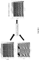
- FIG. 1 describes the data processing steps employed in our tests.
- step 101 the DAS data was measured and recorded as described above.
- additional data collection can also be implemented to corroborate the DAS data.
- step 103 the DTS data was measured and recorded as described above.
- the recording of DAS and DTS should be simultaneous and covering the same section of the monitored well.
- additional data collection can also be implemented to corroborate the DTS data.
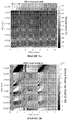
- the optic fiber cable is either situated in an injection/production well for real-time monitoring of injection/production progress, or in an offset well to determine for example the payzone condition, fracking effectiveness, or production interference. In our test, the cable was cemented outside the tubing string of a production well. Exemplary DTS and DAS data are shown in FIGs. 2A and 2B , respectively.
- step 105 the DAS recordings were low-pass filtered and down sampled to generate low-frequency DAS data.
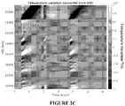
- step 107 the low-frequency DAS data were converted to temperature variation. Exemplary converted temperature variation is shown in FIG. 2C .
- step 109 the DTS and converted DAS data were combined.
- the combining was performed by a computer processor, which in step 109 fit both sets data to the temperature function T(x,t) by minimizing the error function ⁇ in Equation (2).
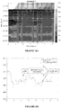
- FIG. 4 Further shown in FIG. 4 is a comparison that shows the temperature estimation obtained by the disclosed method and by DTS measurement alone at the measure depth 4267 m (14000 ft). As shown, the estimation obtained according to this disclosure has a much more accurate (about four orders of magnitude) temperature measurement than the DTS measurement alone. Further, the sampling and response time was also instantaneous thanks to the interrogating frequency.
- the data processing method can also be used to monitor well performance over a long period of time, such that any significant change in production profile can be addressed with adjusted completion designs.
- FIG. 5 An exemplary well system is shown in FIG. 5 .
- the evaluation and production system 10 associated with a borehole 12 is shown.
- a borehole string 14 is disposed in the borehole 12, which penetrates at least one earth formation 16 for facilitating operations such as drilling, production and making measurements of properties of the borehole 12 and/or the formation 16.
- the borehole string 14 includes any of various components to facilitate subterranean operations.
- the borehole string 14 is made from, for example, a pipe, multiple pipe sections or flexible tubing.
- the borehole string 14 includes for example, a drilling system and/or a bottomhole assembly (BHA).
- BHA bottomhole assembly
- the system 10 and/or the borehole string 14 include any number of downhole tools 18 for various processes including drilling, hydrocarbon production, and formation evaluation (FE) for measuring one or more physical quantities in or around a borehole.
- Various measurement tools may be incorporated into the system 10 to affect measurement regimes such as wireline measurement applications or logging-while-drilling (LWD) applications.
- the borehole string 14 is configured e.g., as a production string and includes a tool 18 configured as a stimulation assembly as part of, for example, a BHA.
- the stimulation assembly is configured to inject stimulation fluids such as hydraulic fracturing fluids and/or acid stimulation fluids into the formation.
- Stimulation fluids may include any suitable fluid used to reduce or eliminate an impediment to fluid production. But stimulation is not a necessary part of this disclosure.
- the system 10 includes one or more injection assemblies 20 configured to control injection of stimulation fluid and direct stimulation fluid into one or more production zones in the formation.
- Each injection assembly 20 includes, e.g., one or more injection or flow control devices configured to direct stimulation fluid from a conduit in the string 14 to the borehole 12.
- a fluid source 22 may be coupled to a wellhead 24 and injected into the borehole string 14.
- the system 10 also includes one or more fiber optic components configured to perform various functions in the system 10, such as communication and sensing various parameters, especially temperature.
- the fiber optic component includes a fiber optic sensor 26 configured to measure downhole properties such as temperature, pressure, stress, strain, vibration and deformation of downhole components such as the borehole string 14 and the tools 18.
- the optical fiber sensor 26 includes at least one optical fiber having one or more sensing locations disposed along the length of the optical fiber sensor 26. Examples of sensing locations include fiber Bragg gratings (FBG), mirrors, Fabry-Perot cavities and locations of intrinsic scattering. Locations of intrinsic scattering include points in or lengths of the fiber that reflect interrogation signals, such as Rayleigh scattering locations.
- the monitoring system includes an interrogation unit 28 configured to transmit an electromagnetic interrogation signal into the optical fiber sensor 26 and receive a reflected signal from one or more locations in the optical fiber sensor 26.
- the interrogation unit 28 includes components such as a signal source 30 (e.g., a pulsed light source, LED, laser, etc.) and a signal detector 32.
- a processor 34 is in operable communication with the signal source 30 and the detector 32 and is configured to control the source 30 and receive reflected signal data from the detector 32.
- An example of an interrogation unit is a reflectometer unit that includes an OFDR and/or OTDR type interrogator unit.
- the optical fiber sensor 26 is configured as a distributed acoustic sensor (DAS), which includes at least one DAS optical fiber 36, such as a single mode fiber, coupled to the interrogation unit 28.
- DAS distributed acoustic sensor
- the interrogation unit 28 (or other processing device configured to receive interferometer data) is configured to estimate temperature variation based on the DAS signals.
- the system 10 also includes a DTS assembly that includes at least one DTS optical fiber 38, which can be the same or different from 26.
- the DTS fiber can be coupled to a separate interrogation unit or other device for transmitting and receiving signals, or can be coupled to the DAS interrogation unit 28.
- fiber optics used in this disclosure were embedded in the external casing to avoid any undesirable deformation, but that would limit the applicability to wells already having fiber optics.
- the disclosed method provides a mechanism of temperature estimation using DAS/DTS that is up to 10,000 times more accurate than currently available technique that monitors temperature continuously along the borehole.
- the ability to do this accurately has several potential applications as outlined below.
- the inventive method is used during hydraulic fracturing.
- An optical fiber is deployed in an offset monitor well, and the fractures can be detected by monitoring the small temperature variations induced by fracture propagation and injection fluid movement from the stimulation well. Because the disclosed method can now measure up to ⁇ 0.56 ⁇ 10 -4 °C/ s (10 -4 °F/s), fracture propagation can be readily detected because the fracturing fluid has different thermal energy from the non-fractured formation, and the small changes within detecting limits represent the intersection of fractures at the monitor well.
- the inventive method is used during production.
- the borehole fluid temperature distribution slightly varies due to the change of borehole flow rate.
- the borehole fluid flow rate which provides production allocation information. As is known, this type of information can be used to optimize efficiencies of production.
- optical fiber in a non-producing offset monitor well and changing the production rate of the producing well, it is possible to estimate the production interference between these two wells by measuring the small temperature variations induced by the cross flow in the monitor well borehole. As such, the production interference in the field may be minimized adjusting well spacing and completion designs.
- the high-precision temperature estimation obtained from jointly inverting the DAS and DTS data is up to 10,000 times more accurate than the current commercial solution. It is a critical step towards the fiber-optical based production logging.
- the current fiber-based production logging solution that relies solely on DTS measurements fails to yield unique production profiles.
- the new production logging method that combines DTS and DAS is potentially more accurate, unique and reliable.
- the jointly inverted temperature measurements also have many other potential applications, including completion monitoring, cross-well interference testing, and borehole pump integrity checking.
Landscapes
- Physics & Mathematics (AREA)
- Engineering & Computer Science (AREA)
- Life Sciences & Earth Sciences (AREA)
- Geology (AREA)
- Mining & Mineral Resources (AREA)
- Environmental & Geological Engineering (AREA)
- General Life Sciences & Earth Sciences (AREA)
- Remote Sensing (AREA)
- Geophysics (AREA)
- Fluid Mechanics (AREA)
- Geochemistry & Mineralogy (AREA)
- General Physics & Mathematics (AREA)
- Acoustics & Sound (AREA)
- Electromagnetism (AREA)
- Length Measuring Devices By Optical Means (AREA)
- Investigating Or Analysing Materials By Optical Means (AREA)
- Geophysics And Detection Of Objects (AREA)
- Measuring Temperature Or Quantity Of Heat (AREA)
- Measurement Of Mechanical Vibrations Or Ultrasonic Waves (AREA)
- Investigating Or Analyzing Materials By The Use Of Ultrasonic Waves (AREA)
- General Engineering & Computer Science (AREA)
- Operations Research (AREA)
- Measurement Of Velocity Or Position Using Acoustic Or Ultrasonic Waves (AREA)
- Fire-Detection Mechanisms (AREA)
- Burglar Alarm Systems (AREA)
Claims (15)
- Procédé de mesure de variations de température le long d'un puits de forage, le procédé comprenant les étapes consistant à :a) fournir un ou plusieurs câbles de fibre optique le long d'une longueur d'un puits de forage ;b) enregistrer (101) des signaux de détection acoustique distribuée, DAS, le long du puits de forage en utilisant au moins un câble de fibre optique ;c) enregistrer simultanément (103) des signaux de détection de température distribuée, DTS, provenant du puits de forage en utilisant au moins un câble de fibre optique ;d) filtrer passe-bas et réaliser un sous-échantillonnage (105) des signaux DAS pour obtenir des données DAS à basse fréquence ;le procédé étant caractérisé en ce qu'il comprend en outre les étapes consistant à :e) convertir (107) les données DAS à basse fréquence en variation de température en utilisant l'équation suivante (1) :
 f) estimer (109) la température du trou de forage en minimisant la fonction d'erreur ε en utilisant l'équation suivante (2) :
- Procédé selon la revendication 1, dans lequel ledit un ou plusieurs câbles de fibre optique sont incorporés dans un ciment du puits de forage.
- Procédé selon la revendication 1, dans lequel ledit un ou plusieurs câbles de fibre optique sont inclus dans une chaîne de tubes enroulés, un câble métallique ou une tige de carbone dans le puits de forage.
- Procédé selon la revendication 1, dans lequel les signaux DAS et DTS sont obtenus à 0-1 Hz.
- Procédé selon la revendication 1, dans lequel les signaux DAS et DTS sont échantillonnés à plus de 1 kHz, de préférence à plus de 5 kHz, plus préférentiellement à plus de 10 kHz pour éviter le crénelage de la bande haute fréquence.
- Procédé selon la revendication 1, dans lequel les signaux DAS enregistrés sont filtrés passe-bas à 0,001-1 H : et sous-échantillonnés à une fréquence d'échantillonnage de 1 seconde.
- Procédé selon la revendication 1, dans lequel les signaux DAS et DTS sont obtenus à 0-1 Hz et échantillonnés à plus de 1 kHz, de préférence à plus de 5 kHz, plus préférentiellement à plus de 10 kHz pour éviter le crénelage de la bande haute fréquence.
- Procédé selon la revendication 1, dans lequel le puits de forage subit une fracturation, une fermeture, une production, une injection de vapeur/eau, ou une combinaison de celles-ci.
- Système pour mesurer la température dans un puits de forage, comprenant :a) un dispositif de surveillance de détection acoustique distribuée, DAS, incluant une fibre optique (36) qui s'étend sur une longueur d'un puits de forage, dans lequel la fibre optique DAS est couplée à une unité d'interrogation (28) pour émettre des signaux d'interrogation, le dispositif de surveillance DAS détecte des signaux DAS lorsque des variations de température provoquent une déformation de ladite fibre optique ;b) dispositif de détection de température distribuée, DTS, dans lequel ledit dispositif DTS est couplé à ladite fibre optique ou à une seconde fibre optique (38),
le dispositif DTS présentant une unité d'interrogation DTS pour émettre des signaux d'interrogation, et le dispositif DTS présentant une unité de surveillance DTS pour détecter les signaux DTS ;c) un ordinateur couplé au dispositif de surveillance DAS pour enregistrer les signaux DAS détectés par le dispositif de surveillance DAS, l'ordinateur étant également couplé au dispositif DTS pour enregistrer les signaux DTS détectés par le dispositif de surveillance DTS ;dans lequel l'ordinateur est configuré pour exécuter les étapes suivantes pour obtenir une estimation de la température le long dudit puits de forage à partir desdites données DAS et DTS enregistrées :i) traiter les données DAS pour obtenir des données DAS basse fréquence ;le système étant caractérisé en ce que l'ordinateur est en outre configuré pour exécuter les étapes consistant à :
ii) convertir les données DAS basse fréquence en variation de température en utilisant l'équation suivante (1)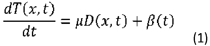 dans lequel D(χ, t) est le DAS basse fréquence, µ est la constante qui convertit le taux de phase optique en variation de température, β(t) est le bruit de dérive existant dans les données DAS.iii) estimer la mesure de la température en minimisant une fonction d'erreur ε en utilisant l'équation suivante (2)
 dans lequel T 0 représente les données DTS, D représente les données basse fréquence, et λ est un paramètre qui détermine l'importance relative de la minimisation de l'inadaptation des données DAS, par rapport à l'inadaptation des données DTS, qui peut dépendre de la fréquence.
 - Procédé selon la revendication 9, dans lequel ledit câble de fibre optique est incorporé dans un ciment du puits de forage.
- Système selon la revendication 9, dans lequel ledit câble de fibre optique est inclus dans une chaîne de tubes enroulés, un câble métallique ou une tige de carbone dans le puits de forage.
- Système selon la revendication 9, dans lequel le puits de forage subit une fracturation, une fermeture, une production, une injection de vapeur, ou une combinaison de celles-ci.
- Système selon la revendication 9, dans lequel les signaux DAS et DTS sont obtenus à 0-1 Hz, éventuellement dans lequel les signaux DAS et DTS sont obtenus à 0-1 Hz et échantillonnés à plus de 1 kHz, de préférence à plus de 5 kHz, plus préférentiellement à plus de 10 kHz pour éviter le crénelage d'une bande haute fréquence.
- Système selon la revendication 9, dans lequel les signaux DAS et DTS sont échantillonnés à >1 kHz pour éviter le crénelage de la bande haute fréquence.
- Système selon la revendication 9, dans lequel les signaux DAS enregistrés sont filtrés passe-bas à 0,001-1 Hz et sous-échantillonnés à une fréquence d'échantillonnage de 1 seconde.
Applications Claiming Priority (4)
| Application Number | Priority Date | Filing Date | Title |
|---|---|---|---|
| US201662305777P | 2016-03-09 | 2016-03-09 | |
| US201662305758P | 2016-03-09 | 2016-03-09 | |
| US15/453,216 US10370957B2 (en) | 2016-03-09 | 2017-03-08 | Measuring downhole temperature by combining DAS/DTS data |
| PCT/US2017/021667 WO2017156328A1 (fr) | 2016-03-09 | 2017-03-09 | Mesure de température de fond de trou par combinaison de données das/dts |
Publications (3)
| Publication Number | Publication Date |
|---|---|
| EP3665449A1 EP3665449A1 (fr) | 2020-06-17 |
| EP3665449A4 EP3665449A4 (fr) | 2021-10-13 |
| EP3665449B1 true EP3665449B1 (fr) | 2022-12-28 |
Family
ID=59786319
Family Applications (5)
| Application Number | Title | Priority Date | Filing Date |
|---|---|---|---|
| EP17764150.3A Active EP3427083B1 (fr) | 2016-03-09 | 2017-03-09 | Détection acoustique distribuée à basse fréquence |
| EP17764141.2A Active EP3665449B1 (fr) | 2016-03-09 | 2017-03-09 | Mesure de température de fond de trou par combinaison de données das/dts |
| EP17764149.5A Active EP3704477B1 (fr) | 2016-03-09 | 2017-03-09 | Surveillance de fracture hydraulique par un das basse fréquence |
| EP17764137.0A Active EP3427045B1 (fr) | 2016-03-09 | 2017-03-09 | Procédé das d'estimation de répartition de fluide |
| EP17764146.1A Withdrawn EP3427018A4 (fr) | 2016-03-09 | 2017-03-09 | Détection acoustique distribuée pour télémétrie de puits |
Family Applications Before (1)
| Application Number | Title | Priority Date | Filing Date |
|---|---|---|---|
| EP17764150.3A Active EP3427083B1 (fr) | 2016-03-09 | 2017-03-09 | Détection acoustique distribuée à basse fréquence |
Family Applications After (3)
| Application Number | Title | Priority Date | Filing Date |
|---|---|---|---|
| EP17764149.5A Active EP3704477B1 (fr) | 2016-03-09 | 2017-03-09 | Surveillance de fracture hydraulique par un das basse fréquence |
| EP17764137.0A Active EP3427045B1 (fr) | 2016-03-09 | 2017-03-09 | Procédé das d'estimation de répartition de fluide |
| EP17764146.1A Withdrawn EP3427018A4 (fr) | 2016-03-09 | 2017-03-09 | Détection acoustique distribuée pour télémétrie de puits |
Country Status (6)
| Country | Link |
|---|---|
| US (5) | US20170260839A1 (fr) |
| EP (5) | EP3427083B1 (fr) |
| AU (5) | AU2017230716B2 (fr) |
| CA (2) | CA3016470A1 (fr) |
| CL (3) | CL2018002553A1 (fr) |
| WO (5) | WO2017156338A1 (fr) |
Families Citing this family (78)
| Publication number | Priority date | Publication date | Assignee | Title |
|---|---|---|---|---|
| US10808521B2 (en) | 2013-05-31 | 2020-10-20 | Conocophillips Company | Hydraulic fracture analysis |
| NL2014518B1 (en) * | 2015-03-25 | 2017-01-17 | Fugro Tech Bv | A device for measuring fluid parameters, a method for measuring fluid parameters and a computer program product. |
| US10281341B2 (en) * | 2015-05-21 | 2019-05-07 | Hifi Engineering Inc. | Methods and systems using optical fiber interferometry |
| GB201522715D0 (en) * | 2015-12-23 | 2016-02-03 | Optasense Holdings Ltd | Fibre optic temperature measurement |
| US20170260839A1 (en) | 2016-03-09 | 2017-09-14 | Conocophillips Company | Das for well ranging |
| US10890058B2 (en) | 2016-03-09 | 2021-01-12 | Conocophillips Company | Low-frequency DAS SNR improvement |
| CA3062569A1 (fr) | 2017-05-05 | 2018-11-08 | Conocophillips Company | Analyse de volume de roche stimulee |
| WO2018204920A1 (fr) | 2017-05-05 | 2018-11-08 | Conocophillips Company | Analyse de volume de roche stimulée |
| US11255997B2 (en) | 2017-06-14 | 2022-02-22 | Conocophillips Company | Stimulated rock volume analysis |
| NO344774B1 (en) * | 2017-10-10 | 2020-04-27 | Petroleum Technology Co As | Downhole device with signal transmitter |
| AU2018352983B2 (en) * | 2017-10-17 | 2024-02-22 | Conocophillips Company | Low frequency distributed acoustic sensing hydraulic fracture geometry |
| CN108119121A (zh) * | 2017-12-11 | 2018-06-05 | 中国石油天然气股份有限公司 | 一种水平井重复压裂潜力井快速筛选方法 |
| CN109958411B (zh) * | 2017-12-22 | 2021-04-02 | 中国石油化工股份有限公司 | 一种水平井簇射孔分段压裂方法 |
| US11487037B2 (en) | 2018-01-09 | 2022-11-01 | Halliburton Energy Services, Inc. | Well monitoring via distributed acoustic sensing subsystem and distributed temperature sensing subsystem |
| CA3094528A1 (fr) * | 2018-03-28 | 2019-10-03 | Conocophillips Company | Evaluation d'interference de puits das basse frequence |
| IL277826B2 (en) * | 2018-04-06 | 2023-10-01 | Ava Risk Group Ltd | Event statistic generation method and apparatus for intrusion detection |
| CA3097930A1 (fr) | 2018-05-02 | 2019-11-07 | Conocophillips Company | Inversion de diagraphie de production basee sur des das/dts |
| US12291943B2 (en) | 2018-05-02 | 2025-05-06 | Conocophillips Company | Production logging inversion based on LFDAS/DTS |
| US11467308B2 (en) * | 2018-05-21 | 2022-10-11 | West Virginia University | Fibro: a fiber optic data processing software for unconventional reservoirs |
| CN108827482B (zh) * | 2018-07-02 | 2019-09-10 | 南昌航空大学 | 对流层大气温度廓线测量方法、装置及控制方法 |
| US20200072995A1 (en) * | 2018-08-29 | 2020-03-05 | Silixa Ltd. | Wireline Optical Fiber Sensing |
| CN109236255B (zh) * | 2018-09-03 | 2020-07-10 | 中国石油大学(华东) | 一种水平井压裂潜力评价方法和装置 |
| WO2020102202A1 (fr) | 2018-11-13 | 2020-05-22 | Motive Drilling Technologies, Inc. | Appareil et procédés pour déterminer des informations d'un puits |
| US11698288B2 (en) * | 2018-11-14 | 2023-07-11 | Saudi Arabian Oil Company | Signal to noise ratio management |
| US11561311B2 (en) * | 2018-12-07 | 2023-01-24 | Halliburton Energy Services, Inc. | Simultaneous acquisition of distributed acoustic sensing for monitoring |
| US11530581B2 (en) * | 2018-12-17 | 2022-12-20 | Exxonmobil Upstream Research Company | Weighted material point method for managing fluid flow in pipes |
| US11293280B2 (en) * | 2018-12-19 | 2022-04-05 | Exxonmobil Upstream Research Company | Method and system for monitoring post-stimulation operations through acoustic wireless sensor network |
| CA3117660C (fr) * | 2018-12-31 | 2023-08-08 | Halliburton Energy Services, Inc. | Detection acoustique distribuee: localisation d'evenements microsismiques a l'aide d'informations de temps de trajet avec un modele de vitesse anisotrope heterogene |
| EP3680638B1 (fr) | 2019-01-11 | 2021-11-03 | AiQ Dienstleistungen UG (haftungsbeschränkt) | Détection acoustique distribuée et surveillance d'intégrité de capteur |
| CN109854220B (zh) * | 2019-01-14 | 2020-11-10 | 中南大学 | 一种适用于低渗储层水力压裂模拟试验的注液管密封方法 |
| CN109933860A (zh) * | 2019-02-25 | 2019-06-25 | 北京科技大学 | 页岩气压裂水平井簇间距优化方法 |
| US10962408B2 (en) | 2019-03-07 | 2021-03-30 | Saudi Arabian Oil Company | Quasi-fundamental-mode operated multimode fiber for distributed acoustic sensing |
| US11768307B2 (en) | 2019-03-25 | 2023-09-26 | Conocophillips Company | Machine-learning based fracture-hit detection using low-frequency DAS signal |
| US11327191B2 (en) * | 2019-05-02 | 2022-05-10 | Saudi Arabian Oil Company | Seismic mono-frequency workflow for direct gas reservoir detection |
| CN110159240B (zh) * | 2019-06-19 | 2020-09-22 | 中国地质大学(北京) | 一种煤层气开采压裂设备 |
| CN110344816B (zh) * | 2019-07-16 | 2023-05-09 | 中国石油大学(华东) | 一种基于分布式光纤声音监测的油气井出砂监测方法 |
| CN112240195B (zh) * | 2019-07-16 | 2024-01-30 | 中国石油大学(华东) | 基于分布式光纤声音监测的油气井出砂监测模拟实验装置及工作方法 |
| WO2021013829A1 (fr) * | 2019-07-22 | 2021-01-28 | Tore Kjos | Procédé et système d'étude sismique |
| CN110286421B (zh) * | 2019-08-09 | 2020-12-18 | 中国石油大学(华东) | 一种致密砂岩储层天然裂缝建模方法 |
| US10880007B1 (en) | 2019-08-15 | 2020-12-29 | Saudi Arabian Oil Company | Simultaneous distributed temperature and vibration sensing using multimode optical fiber |
| US11556612B2 (en) * | 2019-09-09 | 2023-01-17 | Halliburton Energy Services, Inc. | Predicting material distribution in a hydraulic fracturing treatment stage |
| US12130394B2 (en) * | 2019-10-03 | 2024-10-29 | Schlumberger Technology Corporation | Fiber optic interrogation system |
| CA3151611C (fr) * | 2019-10-31 | 2023-12-19 | Halliburton Energy Services, Inc. | Localisation d'evenements sismiques passifs dans un puits de forage a l'aide d'une detection acoustique distribuee |
| US12196605B2 (en) | 2019-11-25 | 2025-01-14 | Nec Corporation | Position detection device and position detection method |
| CN110849461B (zh) * | 2019-12-04 | 2021-08-31 | 江苏方天电力技术有限公司 | 一种调相机振动信号采集与存储方法、系统 |
| US12000268B2 (en) | 2019-12-27 | 2024-06-04 | Adams Testing Services, Inc. | Hydraulic pressure testing system, and method of testing tubular products |
| US11920464B2 (en) | 2020-01-31 | 2024-03-05 | Halliburton Energy Services, Inc. | Thermal analysis of temperature data collected from a distributed temperature sensor system for estimating thermal properties of a wellbore |
| US11828171B2 (en) | 2020-03-18 | 2023-11-28 | Chevron U.S.A. Inc. | System and method for preventing wellbore interactions |
| CN111444612B (zh) * | 2020-03-26 | 2021-04-16 | 北京科技大学 | 一种致密油藏水平井多级压裂流场形态模拟方法 |
| US11339636B2 (en) | 2020-05-04 | 2022-05-24 | Saudi Arabian Oil Company | Determining the integrity of an isolated zone in a wellbore |
| US20210364669A1 (en) * | 2020-05-19 | 2021-11-25 | Halliburton Energy Services, Inc. | Multi-well interference control and mitigation |
| US11519767B2 (en) | 2020-09-08 | 2022-12-06 | Saudi Arabian Oil Company | Determining fluid parameters |
| US11920469B2 (en) | 2020-09-08 | 2024-03-05 | Saudi Arabian Oil Company | Determining fluid parameters |
| US11656112B2 (en) * | 2020-11-19 | 2023-05-23 | International Business Machines Corporation | Acoustic fluids monitoring |
| WO2022155594A1 (fr) | 2021-01-15 | 2022-07-21 | Conocophillips Company | Analyse d'intégrité hydraulique |
| US11530597B2 (en) | 2021-02-18 | 2022-12-20 | Saudi Arabian Oil Company | Downhole wireless communication |
| US11603756B2 (en) | 2021-03-03 | 2023-03-14 | Saudi Arabian Oil Company | Downhole wireless communication |
| US20220283330A1 (en) * | 2021-03-03 | 2022-09-08 | Halliburton Energy Services, Inc. | Gauge Length Correction For Seismic Attenuation From Distributed Acoustic System Fiber Optic Data |
| US11644351B2 (en) | 2021-03-19 | 2023-05-09 | Saudi Arabian Oil Company | Multiphase flow and salinity meter with dual opposite handed helical resonators |
| US11913464B2 (en) | 2021-04-15 | 2024-02-27 | Saudi Arabian Oil Company | Lubricating an electric submersible pump |
| US11619114B2 (en) | 2021-04-15 | 2023-04-04 | Saudi Arabian Oil Company | Entering a lateral branch of a wellbore with an assembly |
| CA3154347A1 (fr) * | 2021-04-16 | 2022-10-16 | Husky Oil Operations Limited | Systeme et methode pour surveiller la progression d'une chambre de vapeur en subsurface au moyen de cables a fibres optiques |
| US12332394B2 (en) * | 2021-06-01 | 2025-06-17 | Nec Corporation | Fiber sensing using supervisory path of submarine cables |
| CA3225345A1 (fr) | 2021-07-16 | 2023-01-19 | Conocophillips Company | Instrument de diagraphie de production passif utilisant la chaleur et la detection acoustique distribuee |
| US11994016B2 (en) | 2021-12-09 | 2024-05-28 | Saudi Arabian Oil Company | Downhole phase separation in deviated wells |
| US12085687B2 (en) | 2022-01-10 | 2024-09-10 | Saudi Arabian Oil Company | Model-constrained multi-phase virtual flow metering and forecasting with machine learning |
| US12092779B2 (en) * | 2022-01-31 | 2024-09-17 | Halliburton Energy Services, Inc. | Simultaneous distributed acoustic sensing with multiple gauge lengths |
| US12153180B2 (en) | 2022-03-22 | 2024-11-26 | Saudi Arabian Oil Company | ISO-frequency ratio logs |
| US20240133281A1 (en) * | 2022-04-15 | 2024-04-25 | Southwest Petroleum University | Calculation systems for predicting proppant embedding depth based on shale softening effect |
| US12436043B2 (en) * | 2022-09-29 | 2025-10-07 | The Government Of The United States Of America, As Represented By The Secretary Of The Navy | Methods providing distributed temperature and strain measurements and related sensors |
| US12305501B2 (en) * | 2022-10-31 | 2025-05-20 | Saudi Arabian Oil Company | Distributed fiber sensing in a packer for permanent casing and formation deformation monitoring |
| WO2024107815A1 (fr) * | 2022-11-15 | 2024-05-23 | Schlumberger Technology Corporation | Procédé de détection automatisé d'événement sismique pour traitement de données de détection acoustique distribuées de fond de trou |
| US12242009B2 (en) | 2022-12-07 | 2025-03-04 | Saudi Arabian Oil Company | Method and system for measuring strain rate at a scale shorter than gauge length |
| US20240405890A1 (en) * | 2023-06-01 | 2024-12-05 | Nec Laboratories America, Inc. | Fiber-optic acoustic antenna array as an acoustic communication system |
| US12546215B2 (en) * | 2024-01-09 | 2026-02-10 | Ifdata Llc | Fracking efficiency evaluation system and method(s) of use |
| CN117553903B (zh) * | 2024-01-10 | 2024-05-24 | 三峡金沙江云川水电开发有限公司 | 一种基于光纤传感的大型变压器运输监测方法及系统 |
| CN118091185B (zh) * | 2024-04-26 | 2024-07-02 | 中国科学院地质与地球物理研究所 | 点源主动加热分布式光纤测量多层地下水流量流速的方法 |
| WO2026102396A1 (fr) * | 2024-11-08 | 2026-05-15 | Conocophillips Company | Système et procédé de déconvolution d'une détection acoustique distribuée dans un puits |
Family Cites Families (71)
| Publication number | Priority date | Publication date | Assignee | Title |
|---|---|---|---|---|
| US3981187A (en) | 1974-03-25 | 1976-09-21 | Atlantic Richfield Company | Method for measuring the thermal conductivity of well casing and the like |
| US4676664A (en) | 1983-07-15 | 1987-06-30 | The Trustees Of Columbia University In The City Of New York | Exploring for subsurface hydrocarbons by sea floor temperature gradients preferably using a multiplexed thermistor probe |
| US6787758B2 (en) | 2001-02-06 | 2004-09-07 | Baker Hughes Incorporated | Wellbores utilizing fiber optic-based sensors and operating devices |
| WO1998050681A1 (fr) | 1997-05-02 | 1998-11-12 | Baker Hughes Incorporated | Puits utilisant des detecteurs et des equipements operationnels a base de fibres optiques |
| AU8164898A (en) | 1997-06-27 | 1999-01-19 | Baker Hughes Incorporated | Drilling system with sensors for determining properties of drilling fluid downhole |
| US6026913A (en) | 1997-09-30 | 2000-02-22 | Halliburton Energy Services, Inc. | Acoustic method of connecting boreholes for multi-lateral completion |
| US6665117B2 (en) | 1999-05-06 | 2003-12-16 | Conocophillips Company | Method and apparatus for interactive curved surface borehole interpretation and visualization |
| AU2282501A (en) | 1999-12-27 | 2001-07-09 | Ball Corporation | Autonomous omnidirectional driller |
| US7028772B2 (en) | 2000-04-26 | 2006-04-18 | Pinnacle Technologies, Inc. | Treatment well tiltmeter system |
| US6778720B1 (en) | 2002-04-02 | 2004-08-17 | Optiphase, Inc. | Dual slope fiber optic array interrogator |
| GB0521713D0 (en) | 2005-10-25 | 2005-11-30 | Qinetiq Ltd | Traffic sensing and monitoring apparatus |
| US8326540B2 (en) | 2007-02-15 | 2012-12-04 | HiFi Engineering, Inc. | Method and apparatus for fluid migration profiling |
| CA2700732A1 (fr) | 2007-10-19 | 2009-04-23 | Shell Internationale Research Maatschappij B.V. | Traitement cryogenique de gaz |
| US7946341B2 (en) * | 2007-11-02 | 2011-05-24 | Schlumberger Technology Corporation | Systems and methods for distributed interferometric acoustic monitoring |
| WO2009073008A1 (fr) | 2007-12-06 | 2009-06-11 | Halliburton Energy Services, Inc. | Guidage acoustique pour un placement de puits de forage |
| US7668411B2 (en) | 2008-06-06 | 2010-02-23 | Schlumberger Technology Corporation | Distributed vibration sensing system using multimode fiber |
| WO2010056353A2 (fr) | 2008-11-17 | 2010-05-20 | SensorTran, Inc | Sonde thermique à fibre optique, à haute résolution spatiale |
| US20100200743A1 (en) | 2009-02-09 | 2010-08-12 | Larry Dale Forster | Well collision avoidance using distributed acoustic sensing |
| GB0905986D0 (en) | 2009-04-07 | 2009-05-20 | Qinetiq Ltd | Remote sensing |
| PL228478B1 (pl) * | 2009-05-27 | 2018-04-30 | Qinetiq Ltd | Sposób wgłębnego monitoringu hydraulicznego szczelinowania, układ do wgłębnego monitoringu oraz zastosowanie układu |
| US20110019178A1 (en) * | 2009-07-22 | 2011-01-27 | Christos Vlatas | Method for post processing fiber optic strain measurement data |
| US8746333B2 (en) | 2009-11-30 | 2014-06-10 | Technological Research Ltd | System and method for increasing production capacity of oil, gas and water wells |
| WO2011079098A2 (fr) | 2009-12-23 | 2011-06-30 | Shell Oil Company | Détection de signaux acoustiques large bande et directionnels à l'aide d'un ensemble de détection acoustique répartie (das) à fibre optique |
| US8505625B2 (en) | 2010-06-16 | 2013-08-13 | Halliburton Energy Services, Inc. | Controlling well operations based on monitored parameters of cement health |
| US8930143B2 (en) | 2010-07-14 | 2015-01-06 | Halliburton Energy Services, Inc. | Resolution enhancement for subterranean well distributed optical measurements |
| US8864374B2 (en) | 2010-08-13 | 2014-10-21 | Qorex Llc | Low profile, high temperature, hydrogen tolerant optical sensing cable |
| US9170149B2 (en) | 2010-09-01 | 2015-10-27 | Schlumberger Technology Corporation | Distributed fiber optic sensor system with improved linearity |
| GB201020358D0 (en) | 2010-12-01 | 2011-01-12 | Qinetiq Ltd | Fracture characterisation |
| US8740455B2 (en) | 2010-12-08 | 2014-06-03 | Baker Hughes Incorporated | System and method for distributed environmental parameter measurement |
| CN103270244B (zh) | 2010-12-21 | 2017-12-01 | 国际壳牌研究有限公司 | 测试应变和压力的系统和方法 |
| WO2012084040A1 (fr) | 2010-12-22 | 2012-06-28 | Omnisens Sa | Procédé et appareil de mesure optoélectroniques de brillouin |
| GB201102930D0 (en) | 2011-02-21 | 2011-04-06 | Qinetiq Ltd | Techniques for distributed acoustic sensing |
| GB201104423D0 (en) * | 2011-03-16 | 2011-04-27 | Qinetiq Ltd | Subsurface monitoring using distributed accoustic sensors |
| US9347313B2 (en) | 2011-06-13 | 2016-05-24 | Shell Oil Company | Hydraulic fracture monitoring using active seismic sources with receivers in the treatment well |
| GB2492802A (en) | 2011-07-13 | 2013-01-16 | Statoil Petroleum As | Using distributed acoustic measurements for surveying a hydrocarbon producing well and for compensating other acoustic measurements |
| US8864599B2 (en) | 2011-07-18 | 2014-10-21 | Swing-Wright, Llc | Teaching aid |
| WO2013028515A2 (fr) | 2011-08-19 | 2013-02-28 | US Seismic Systems, Inc. | Systèmes de détection de fuite de puits de forage et leurs procédés d'utilisation |
| GB201116816D0 (en) | 2011-09-29 | 2011-11-09 | Qintetiq Ltd | Flow monitoring |
| GB201122027D0 (en) | 2011-12-20 | 2012-02-01 | Bp Exploration Operating | Estimating flow in production well |
| WO2013185225A1 (fr) * | 2012-06-11 | 2013-12-19 | Kobold Services Inc. | Contrôle microsismique avec cartographie de bruit sur fibres optiques |
| US9273548B2 (en) * | 2012-10-10 | 2016-03-01 | Halliburton Energy Services, Inc. | Fiberoptic systems and methods detecting EM signals via resistive heating |
| US20140126325A1 (en) | 2012-11-02 | 2014-05-08 | Silixa Ltd. | Enhanced seismic surveying |
| US9388685B2 (en) | 2012-12-22 | 2016-07-12 | Halliburton Energy Services, Inc. | Downhole fluid tracking with distributed acoustic sensing |
| US20140202240A1 (en) * | 2013-01-24 | 2014-07-24 | Halliburton Energy Services, Inc. | Flow velocity and acoustic velocity measurement with distributed acoustic sensing |
| US20140260588A1 (en) | 2013-03-12 | 2014-09-18 | Halliburton Energy Services | Flow Sensing Fiber Optic Cable and System |
| US20140358444A1 (en) | 2013-05-31 | 2014-12-04 | Conocophillips Company | Method of hydraulic fracture identification using temperature |
| NO347403B1 (en) | 2013-06-13 | 2023-10-16 | Schlumberger Technology Bv | Fiber optic distributed vibration sensing with wavenumber sensitivity correction |
| US9091155B2 (en) | 2013-07-10 | 2015-07-28 | Halliburton Energy Services, Inc. | Reducing disturbance during fiber optic sensing |
| GB201312549D0 (en) | 2013-07-12 | 2013-08-28 | Fotech Solutions Ltd | Monitoring of hydraulic fracturing operations |
| US10087751B2 (en) * | 2013-08-20 | 2018-10-02 | Halliburton Energy Services, Inc. | Subsurface fiber optic stimulation-flow meter |
| CA2926411C (fr) | 2013-10-28 | 2022-07-05 | Petrus Hendrikus Maria Wilhemus IN'T PANHUIS | Procede et systeme pour surveiller un ecoulement de fluide dans un conduit |
| GB201319553D0 (en) * | 2013-11-05 | 2013-12-18 | Optasense Holdings Ltd | Monitoring of steam injection |
| US10208586B2 (en) | 2013-11-25 | 2019-02-19 | Baker Hughes, A Ge Company, Llc | Temperature sensing using distributed acoustic sensing |
| US9556723B2 (en) | 2013-12-09 | 2017-01-31 | Baker Hughes Incorporated | Geosteering boreholes using distributed acoustic sensing |
| AU2013408391B2 (en) | 2013-12-17 | 2017-06-08 | Halliburton Energy Services, Inc. | Distributed acoustic sensing for passive ranging |
| GB2522061A (en) | 2014-01-14 | 2015-07-15 | Optasense Holdings Ltd | Determining sensitivity profiles for DAS sensors |
| GB201408131D0 (en) | 2014-05-08 | 2014-06-25 | Optasense Holdings Ltd | Fluid inflow |
| GB201408125D0 (en) | 2014-05-08 | 2014-06-25 | Optasense Holdings Ltd | Fibre optic distributed sensing |
| CA2891100A1 (fr) | 2014-05-16 | 2015-11-16 | Aaron SCOLLARD | Plan de puits interactif |
| CA2947576C (fr) | 2014-06-04 | 2022-11-22 | Halliburton Energy Services, Inc. | Evaluation d'un modele de propagation de fracture sur la base de donnees sismiques |
| WO2015187149A1 (fr) | 2014-06-04 | 2015-12-10 | Halliburton Energy Services, Inc. | Surveillance de la saturation souterraine en hydrocarbures à l'aide d'une détection acoustique répartie |
| CA2946179C (fr) | 2014-06-04 | 2023-10-17 | Halliburton Energy Services, Inc. | Analyse de traitement de fracture sur la base d'une detection acoustique repartie |
| US20160003032A1 (en) | 2014-07-07 | 2016-01-07 | Conocophillips Company | Matrix temperature production logging tool |
| GB2542726B (en) | 2014-07-10 | 2021-03-10 | Schlumberger Holdings | Distributed fiber optic monitoring of vibration to generate a noise log to determine characteristics of fluid flow |
| WO2016060688A1 (fr) | 2014-10-17 | 2016-04-21 | Halliburton Energy Services, Inc. | Procédés et systèmes utilisant un modèle de prédiction de débit fondé sur une activité acoustique et une compensation d'un agent de soutènement |
| US10012069B2 (en) | 2014-10-31 | 2018-07-03 | Schlumberger Technology Corporation | Method of treatment design and optimization of sequenced fracturing technique |
| CA2987721C (fr) | 2015-08-31 | 2022-02-08 | Halliburton Energy Services, Inc. | Procedes et systemes utilisant un modele de prediction de debit qui est fonction de la geometrie en grappes des perforations, des caracteristiques de fluide, et de l'activite acou stique |
| US10890058B2 (en) | 2016-03-09 | 2021-01-12 | Conocophillips Company | Low-frequency DAS SNR improvement |
| US20170260839A1 (en) | 2016-03-09 | 2017-09-14 | Conocophillips Company | Das for well ranging |
| US10095828B2 (en) | 2016-03-09 | 2018-10-09 | Conocophillips Company | Production logs from distributed acoustic sensors |
| US20180230049A1 (en) | 2017-02-13 | 2018-08-16 | Baker Hughes Incorporated | Downhole optical fiber with array of fiber bragg gratings and carbon-coating |
-
2017
- 2017-03-08 US US15/453,517 patent/US20170260839A1/en not_active Abandoned
- 2017-03-08 US US15/453,434 patent/US10458228B2/en active Active
- 2017-03-08 US US15/453,650 patent/US10287874B2/en active Active
- 2017-03-08 US US15/453,216 patent/US10370957B2/en active Active
- 2017-03-08 US US15/453,044 patent/US10465501B2/en active Active
- 2017-03-09 AU AU2017230716A patent/AU2017230716B2/en active Active
- 2017-03-09 EP EP17764150.3A patent/EP3427083B1/fr active Active
- 2017-03-09 CA CA3016470A patent/CA3016470A1/fr not_active Abandoned
- 2017-03-09 AU AU2017230724A patent/AU2017230724A1/en not_active Abandoned
- 2017-03-09 WO PCT/US2017/021679 patent/WO2017156338A1/fr not_active Ceased
- 2017-03-09 AU AU2017230721A patent/AU2017230721B2/en active Active
- 2017-03-09 AU AU2017230728A patent/AU2017230728B2/en active Active
- 2017-03-09 EP EP17764141.2A patent/EP3665449B1/fr active Active
- 2017-03-09 CA CA3012708A patent/CA3012708A1/fr active Pending
- 2017-03-09 WO PCT/US2017/021674 patent/WO2017156334A1/fr not_active Ceased
- 2017-03-09 WO PCT/US2017/021678 patent/WO2017156337A1/fr not_active Ceased
- 2017-03-09 EP EP17764149.5A patent/EP3704477B1/fr active Active
- 2017-03-09 EP EP17764137.0A patent/EP3427045B1/fr active Active
- 2017-03-09 WO PCT/US2017/021667 patent/WO2017156328A1/fr not_active Ceased
- 2017-03-09 EP EP17764146.1A patent/EP3427018A4/fr not_active Withdrawn
- 2017-03-09 WO PCT/US2017/021659 patent/WO2017156323A1/fr not_active Ceased
- 2017-03-09 AU AU2017230727A patent/AU2017230727B2/en active Active
-
2018
- 2018-09-06 CL CL2018002553A patent/CL2018002553A1/es unknown
- 2018-09-06 CL CL2018002554A patent/CL2018002554A1/es unknown
- 2018-09-06 CL CL2018002557A patent/CL2018002557A1/es unknown
Also Published As
Similar Documents
| Publication | Publication Date | Title |
|---|---|---|
| US10370957B2 (en) | Measuring downhole temperature by combining DAS/DTS data | |
| US10208586B2 (en) | Temperature sensing using distributed acoustic sensing | |
| US6751556B2 (en) | Technique and system for measuring a characteristic in a subterranean well | |
| EP3427017B1 (fr) | Journaux de production provenant de capteurs acoustiques distribués | |
| CA3055290C (fr) | Mesure de temperature a l'aide d'une combinaison d'interferometrie a retrodiffusion rayleigh et raman | |
| US9200508B2 (en) | Method and apparatus for monitoring vibration using fiber optic sensors | |
| US8476583B2 (en) | System and method for wellbore monitoring | |
| EP3137735B1 (fr) | Détection acoustique distribuée à l'aide de faibles taux de répétition d'impulsions | |
| US20120176250A1 (en) | System and method for integrated downhole sensing and optical fiber monitoring | |
| RU2654356C1 (ru) | Двухконечный распределенный датчик температуры с набором датчиков температуры | |
| US20190169985A1 (en) | Simultaneous distributed measurements on optical fiber | |
| US20200032644A1 (en) | Temperature-corrected distributed fiber-optic sensing | |
| EP3134615B1 (fr) | Correction d'atténuation pour des capteurs de température répartis à l'aide de rapport d'anti-stokes à rayleigh | |
| NO20191476A1 (en) | Dispersion-shifted optical fibers for downhole sensing | |
| CA2490107C (fr) | Technique et systeme de mesure d'une caracteristique dans un puits souterrain | |
| Jin et al. | Calibration of Double-Ended Distributed Temperature Sensing System for Production Logging | |
| NO347099B1 (en) | Downhole microseismic detection for passive ranging to a target wellbore | |
| US20250334048A1 (en) | Monitoring downhole components of completion assembly using distributed acoustic sensing | |
| Ahmed | Critical Analysis and Application of Optical Fiber Sensors in Oil and Gas Industry | |
| WO2025226368A1 (fr) | Surveillance de composants de fond de trou d'ensemble d'achèvement à l'aide d'une détection acoustique distribuée |
Legal Events
| Date | Code | Title | Description |
|---|---|---|---|
| STAA | Information on the status of an ep patent application or granted ep patent |
Free format text: STATUS: THE INTERNATIONAL PUBLICATION HAS BEEN MADE |
|
| STAA | Information on the status of an ep patent application or granted ep patent |
Free format text: STATUS: THE APPLICATION IS DEEMED TO BE WITHDRAWN |
|
| PUAI | Public reference made under article 153(3) epc to a published international application that has entered the european phase |
Free format text: ORIGINAL CODE: 0009012 |
|
| 17P | Request for examination filed |
Effective date: 20191108 |
|
| 18D | Application deemed to be withdrawn |
Effective date: 20181010 |
|
| AK | Designated contracting states |
Kind code of ref document: A1 Designated state(s): AL AT BE BG CH CY CZ DE DK EE ES FI FR GB GR HR HU IE IS IT LI LT LU LV MC MK MT NL NO PL PT RO RS SE SI SK SM TR |
|
| STAA | Information on the status of an ep patent application or granted ep patent |
Free format text: STATUS: REQUEST FOR EXAMINATION WAS MADE |
|
| D18D | Application deemed to be withdrawn (deleted) | ||
| A4 | Supplementary search report drawn up and despatched |
Effective date: 20210913 |
|
| RIC1 | Information provided on ipc code assigned before grant |
Ipc: G01V 1/40 20060101ALN20210907BHEP Ipc: G01V 1/22 20060101ALI20210907BHEP Ipc: G01K 11/32 20210101ALI20210907BHEP Ipc: E21B 47/135 20120101ALI20210907BHEP Ipc: E21B 47/07 20120101ALI20210907BHEP Ipc: E21B 47/0224 20120101ALI20210907BHEP Ipc: E21B 47/0228 20120101ALI20210907BHEP Ipc: E21B 43/01 20060101ALI20210907BHEP Ipc: G01H 9/00 20060101AFI20210907BHEP |
|
| GRAP | Despatch of communication of intention to grant a patent |
Free format text: ORIGINAL CODE: EPIDOSNIGR1 |
|
| STAA | Information on the status of an ep patent application or granted ep patent |
Free format text: STATUS: GRANT OF PATENT IS INTENDED |
|
| RIC1 | Information provided on ipc code assigned before grant |
Ipc: G01V 1/40 20060101ALN20220602BHEP Ipc: G01V 1/22 20060101ALI20220602BHEP Ipc: G01K 11/32 20060101ALI20220602BHEP Ipc: E21B 47/135 20120101ALI20220602BHEP Ipc: E21B 47/07 20120101ALI20220602BHEP Ipc: E21B 47/0224 20120101ALI20220602BHEP Ipc: E21B 47/0228 20120101ALI20220602BHEP Ipc: E21B 43/01 20060101ALI20220602BHEP Ipc: G01H 9/00 20060101AFI20220602BHEP |
|
| INTG | Intention to grant announced |
Effective date: 20220623 |
|
| GRAS | Grant fee paid |
Free format text: ORIGINAL CODE: EPIDOSNIGR3 |
|
| GRAA | (expected) grant |
Free format text: ORIGINAL CODE: 0009210 |
|
| STAA | Information on the status of an ep patent application or granted ep patent |
Free format text: STATUS: THE PATENT HAS BEEN GRANTED |
|
| AK | Designated contracting states |
Kind code of ref document: B1 Designated state(s): AL AT BE BG CH CY CZ DE DK EE ES FI FR GB GR HR HU IE IS IT LI LT LU LV MC MK MT NL NO PL PT RO RS SE SI SK SM TR |
|
| RAP1 | Party data changed (applicant data changed or rights of an application transferred) |
Owner name: CONOCOPHILLIPS COMPANY |
|
| REG | Reference to a national code |
Ref country code: GB Ref legal event code: FG4D |
|
| REG | Reference to a national code |
Ref country code: CH Ref legal event code: EP |
|
| REG | Reference to a national code |
Ref country code: DE Ref legal event code: R096 Ref document number: 602017065035 Country of ref document: DE |
|
| REG | Reference to a national code |
Ref country code: AT Ref legal event code: REF Ref document number: 1540779 Country of ref document: AT Kind code of ref document: T Effective date: 20230115 |
|
| REG | Reference to a national code |
Ref country code: IE Ref legal event code: FG4D |
|
| REG | Reference to a national code |
Ref country code: NO Ref legal event code: T2 Effective date: 20221228 |
|
| REG | Reference to a national code |
Ref country code: LT Ref legal event code: MG9D |
|
| PG25 | Lapsed in a contracting state [announced via postgrant information from national office to epo] |
Ref country code: SE Free format text: LAPSE BECAUSE OF FAILURE TO SUBMIT A TRANSLATION OF THE DESCRIPTION OR TO PAY THE FEE WITHIN THE PRESCRIBED TIME-LIMIT Effective date: 20221228 Ref country code: LT Free format text: LAPSE BECAUSE OF FAILURE TO SUBMIT A TRANSLATION OF THE DESCRIPTION OR TO PAY THE FEE WITHIN THE PRESCRIBED TIME-LIMIT Effective date: 20221228 Ref country code: FI Free format text: LAPSE BECAUSE OF FAILURE TO SUBMIT A TRANSLATION OF THE DESCRIPTION OR TO PAY THE FEE WITHIN THE PRESCRIBED TIME-LIMIT Effective date: 20221228 |
|
| REG | Reference to a national code |
Ref country code: NL Ref legal event code: MP Effective date: 20221228 |
|
| REG | Reference to a national code |
Ref country code: AT Ref legal event code: MK05 Ref document number: 1540779 Country of ref document: AT Kind code of ref document: T Effective date: 20221228 |
|
| PG25 | Lapsed in a contracting state [announced via postgrant information from national office to epo] |
Ref country code: RS Free format text: LAPSE BECAUSE OF FAILURE TO SUBMIT A TRANSLATION OF THE DESCRIPTION OR TO PAY THE FEE WITHIN THE PRESCRIBED TIME-LIMIT Effective date: 20221228 Ref country code: LV Free format text: LAPSE BECAUSE OF FAILURE TO SUBMIT A TRANSLATION OF THE DESCRIPTION OR TO PAY THE FEE WITHIN THE PRESCRIBED TIME-LIMIT Effective date: 20221228 Ref country code: HR Free format text: LAPSE BECAUSE OF FAILURE TO SUBMIT A TRANSLATION OF THE DESCRIPTION OR TO PAY THE FEE WITHIN THE PRESCRIBED TIME-LIMIT Effective date: 20221228 Ref country code: GR Free format text: LAPSE BECAUSE OF FAILURE TO SUBMIT A TRANSLATION OF THE DESCRIPTION OR TO PAY THE FEE WITHIN THE PRESCRIBED TIME-LIMIT Effective date: 20230329 |
|
| PG25 | Lapsed in a contracting state [announced via postgrant information from national office to epo] |
Ref country code: NL Free format text: LAPSE BECAUSE OF FAILURE TO SUBMIT A TRANSLATION OF THE DESCRIPTION OR TO PAY THE FEE WITHIN THE PRESCRIBED TIME-LIMIT Effective date: 20221228 |
|
| PG25 | Lapsed in a contracting state [announced via postgrant information from national office to epo] |
Ref country code: SM Free format text: LAPSE BECAUSE OF FAILURE TO SUBMIT A TRANSLATION OF THE DESCRIPTION OR TO PAY THE FEE WITHIN THE PRESCRIBED TIME-LIMIT Effective date: 20221228 Ref country code: RO Free format text: LAPSE BECAUSE OF FAILURE TO SUBMIT A TRANSLATION OF THE DESCRIPTION OR TO PAY THE FEE WITHIN THE PRESCRIBED TIME-LIMIT Effective date: 20221228 Ref country code: PT Free format text: LAPSE BECAUSE OF FAILURE TO SUBMIT A TRANSLATION OF THE DESCRIPTION OR TO PAY THE FEE WITHIN THE PRESCRIBED TIME-LIMIT Effective date: 20230428 Ref country code: ES Free format text: LAPSE BECAUSE OF FAILURE TO SUBMIT A TRANSLATION OF THE DESCRIPTION OR TO PAY THE FEE WITHIN THE PRESCRIBED TIME-LIMIT Effective date: 20221228 Ref country code: EE Free format text: LAPSE BECAUSE OF FAILURE TO SUBMIT A TRANSLATION OF THE DESCRIPTION OR TO PAY THE FEE WITHIN THE PRESCRIBED TIME-LIMIT Effective date: 20221228 Ref country code: CZ Free format text: LAPSE BECAUSE OF FAILURE TO SUBMIT A TRANSLATION OF THE DESCRIPTION OR TO PAY THE FEE WITHIN THE PRESCRIBED TIME-LIMIT Effective date: 20221228 Ref country code: AT Free format text: LAPSE BECAUSE OF FAILURE TO SUBMIT A TRANSLATION OF THE DESCRIPTION OR TO PAY THE FEE WITHIN THE PRESCRIBED TIME-LIMIT Effective date: 20221228 |
|
| PG25 | Lapsed in a contracting state [announced via postgrant information from national office to epo] |
Ref country code: SK Free format text: LAPSE BECAUSE OF FAILURE TO SUBMIT A TRANSLATION OF THE DESCRIPTION OR TO PAY THE FEE WITHIN THE PRESCRIBED TIME-LIMIT Effective date: 20221228 Ref country code: PL Free format text: LAPSE BECAUSE OF FAILURE TO SUBMIT A TRANSLATION OF THE DESCRIPTION OR TO PAY THE FEE WITHIN THE PRESCRIBED TIME-LIMIT Effective date: 20221228 Ref country code: IS Free format text: LAPSE BECAUSE OF FAILURE TO SUBMIT A TRANSLATION OF THE DESCRIPTION OR TO PAY THE FEE WITHIN THE PRESCRIBED TIME-LIMIT Effective date: 20230428 Ref country code: AL Free format text: LAPSE BECAUSE OF FAILURE TO SUBMIT A TRANSLATION OF THE DESCRIPTION OR TO PAY THE FEE WITHIN THE PRESCRIBED TIME-LIMIT Effective date: 20221228 |
|
| REG | Reference to a national code |
Ref country code: DE Ref legal event code: R097 Ref document number: 602017065035 Country of ref document: DE |
|
| REG | Reference to a national code |
Ref country code: DE Ref legal event code: R119 Ref document number: 602017065035 Country of ref document: DE |
|
| PG25 | Lapsed in a contracting state [announced via postgrant information from national office to epo] |
Ref country code: MC Free format text: LAPSE BECAUSE OF FAILURE TO SUBMIT A TRANSLATION OF THE DESCRIPTION OR TO PAY THE FEE WITHIN THE PRESCRIBED TIME-LIMIT Effective date: 20221228 Ref country code: DK Free format text: LAPSE BECAUSE OF FAILURE TO SUBMIT A TRANSLATION OF THE DESCRIPTION OR TO PAY THE FEE WITHIN THE PRESCRIBED TIME-LIMIT Effective date: 20221228 |
|
| REG | Reference to a national code |
Ref country code: CH Ref legal event code: PL |
|
| PLBE | No opposition filed within time limit |
Free format text: ORIGINAL CODE: 0009261 |
|
| STAA | Information on the status of an ep patent application or granted ep patent |
Free format text: STATUS: NO OPPOSITION FILED WITHIN TIME LIMIT |
|
| REG | Reference to a national code |
Ref country code: BE Ref legal event code: MM Effective date: 20230331 |
|
| 26N | No opposition filed |
Effective date: 20230929 |
|
| PG25 | Lapsed in a contracting state [announced via postgrant information from national office to epo] |
Ref country code: LU Free format text: LAPSE BECAUSE OF NON-PAYMENT OF DUE FEES Effective date: 20230309 |
|
| P01 | Opt-out of the competence of the unified patent court (upc) registered |
Effective date: 20231207 |
|
| REG | Reference to a national code |
Ref country code: IE Ref legal event code: MM4A |
|
| PG25 | Lapsed in a contracting state [announced via postgrant information from national office to epo] |
Ref country code: SI Free format text: LAPSE BECAUSE OF FAILURE TO SUBMIT A TRANSLATION OF THE DESCRIPTION OR TO PAY THE FEE WITHIN THE PRESCRIBED TIME-LIMIT Effective date: 20221228 Ref country code: LI Free format text: LAPSE BECAUSE OF NON-PAYMENT OF DUE FEES Effective date: 20230331 Ref country code: IE Free format text: LAPSE BECAUSE OF NON-PAYMENT OF DUE FEES Effective date: 20230309 Ref country code: FR Free format text: LAPSE BECAUSE OF NON-PAYMENT OF DUE FEES Effective date: 20230331 Ref country code: DE Free format text: LAPSE BECAUSE OF NON-PAYMENT OF DUE FEES Effective date: 20231003 Ref country code: CH Free format text: LAPSE BECAUSE OF NON-PAYMENT OF DUE FEES Effective date: 20230331 |
|
| PG25 | Lapsed in a contracting state [announced via postgrant information from national office to epo] |
Ref country code: BE Free format text: LAPSE BECAUSE OF NON-PAYMENT OF DUE FEES Effective date: 20230331 |
|
| PG25 | Lapsed in a contracting state [announced via postgrant information from national office to epo] |
Ref country code: IT Free format text: LAPSE BECAUSE OF FAILURE TO SUBMIT A TRANSLATION OF THE DESCRIPTION OR TO PAY THE FEE WITHIN THE PRESCRIBED TIME-LIMIT Effective date: 20221228 |
|
| PG25 | Lapsed in a contracting state [announced via postgrant information from national office to epo] |
Ref country code: BG Free format text: LAPSE BECAUSE OF FAILURE TO SUBMIT A TRANSLATION OF THE DESCRIPTION OR TO PAY THE FEE WITHIN THE PRESCRIBED TIME-LIMIT Effective date: 20221228 |
|
| PG25 | Lapsed in a contracting state [announced via postgrant information from national office to epo] |
Ref country code: BG Free format text: LAPSE BECAUSE OF FAILURE TO SUBMIT A TRANSLATION OF THE DESCRIPTION OR TO PAY THE FEE WITHIN THE PRESCRIBED TIME-LIMIT Effective date: 20221228 |
|
| PG25 | Lapsed in a contracting state [announced via postgrant information from national office to epo] |
Ref country code: CY Free format text: LAPSE BECAUSE OF FAILURE TO SUBMIT A TRANSLATION OF THE DESCRIPTION OR TO PAY THE FEE WITHIN THE PRESCRIBED TIME-LIMIT; INVALID AB INITIO Effective date: 20170309 |
|
| PG25 | Lapsed in a contracting state [announced via postgrant information from national office to epo] |
Ref country code: HU Free format text: LAPSE BECAUSE OF FAILURE TO SUBMIT A TRANSLATION OF THE DESCRIPTION OR TO PAY THE FEE WITHIN THE PRESCRIBED TIME-LIMIT; INVALID AB INITIO Effective date: 20170309 |
|
| PG25 | Lapsed in a contracting state [announced via postgrant information from national office to epo] |
Ref country code: TR Free format text: LAPSE BECAUSE OF FAILURE TO SUBMIT A TRANSLATION OF THE DESCRIPTION OR TO PAY THE FEE WITHIN THE PRESCRIBED TIME-LIMIT Effective date: 20221228 |
|
| PGFP | Annual fee paid to national office [announced via postgrant information from national office to epo] |
Ref country code: GB Payment date: 20260220 Year of fee payment: 10 |
|
| PGFP | Annual fee paid to national office [announced via postgrant information from national office to epo] |
Ref country code: NO Payment date: 20260223 Year of fee payment: 10 |