EP3665456B1 - Dispositif transducteur avec un ensemble de capteur et procédé pour sa fabrication - Google Patents
Dispositif transducteur avec un ensemble de capteur et procédé pour sa fabrication Download PDFInfo
- Publication number
- EP3665456B1 EP3665456B1 EP18740801.8A EP18740801A EP3665456B1 EP 3665456 B1 EP3665456 B1 EP 3665456B1 EP 18740801 A EP18740801 A EP 18740801A EP 3665456 B1 EP3665456 B1 EP 3665456B1
- Authority
- EP
- European Patent Office
- Prior art keywords
- segment
- wall
- carrier element
- temperature sensor
- end segment
- Prior art date
- Legal status (The legal status is an assumption and is not a legal conclusion. Google has not performed a legal analysis and makes no representation as to the accuracy of the status listed.)
- Active
Links
Images




Classifications
-
- G—PHYSICS
- G01—MEASURING; TESTING
- G01K—MEASURING TEMPERATURE; MEASURING QUANTITY OF HEAT; THERMALLY-SENSITIVE ELEMENTS NOT OTHERWISE PROVIDED FOR
- G01K1/00—Details of thermometers not specially adapted for particular types of thermometer
- G01K1/14—Supports; Fastening devices; Arrangements for mounting thermometers in particular locations
-
- G—PHYSICS
- G01—MEASURING; TESTING
- G01K—MEASURING TEMPERATURE; MEASURING QUANTITY OF HEAT; THERMALLY-SENSITIVE ELEMENTS NOT OTHERWISE PROVIDED FOR
- G01K1/00—Details of thermometers not specially adapted for particular types of thermometer
- G01K1/14—Supports; Fastening devices; Arrangements for mounting thermometers in particular locations
- G01K1/143—Supports; Fastening devices; Arrangements for mounting thermometers in particular locations for measuring surface temperatures
-
- G—PHYSICS
- G01—MEASURING; TESTING
- G01K—MEASURING TEMPERATURE; MEASURING QUANTITY OF HEAT; THERMALLY-SENSITIVE ELEMENTS NOT OTHERWISE PROVIDED FOR
- G01K1/00—Details of thermometers not specially adapted for particular types of thermometer
- G01K1/16—Special arrangements for conducting heat from the object to the sensitive element
-
- G—PHYSICS
- G01—MEASURING; TESTING
- G01K—MEASURING TEMPERATURE; MEASURING QUANTITY OF HEAT; THERMALLY-SENSITIVE ELEMENTS NOT OTHERWISE PROVIDED FOR
- G01K13/00—Thermometers specially adapted for specific purposes
- G01K13/02—Thermometers specially adapted for specific purposes for measuring temperature of moving fluids or granular materials capable of flow
-
- G—PHYSICS
- G01—MEASURING; TESTING
- G01K—MEASURING TEMPERATURE; MEASURING QUANTITY OF HEAT; THERMALLY-SENSITIVE ELEMENTS NOT OTHERWISE PROVIDED FOR
- G01K7/00—Measuring temperature based on the use of electric or magnetic elements directly sensitive to heat ; Power supply therefor, e.g. using thermoelectric elements
- G01K7/02—Measuring temperature based on the use of electric or magnetic elements directly sensitive to heat ; Power supply therefor, e.g. using thermoelectric elements using thermoelectric elements, e.g. thermocouples
-
- G—PHYSICS
- G01—MEASURING; TESTING
- G01K—MEASURING TEMPERATURE; MEASURING QUANTITY OF HEAT; THERMALLY-SENSITIVE ELEMENTS NOT OTHERWISE PROVIDED FOR
- G01K7/00—Measuring temperature based on the use of electric or magnetic elements directly sensitive to heat ; Power supply therefor, e.g. using thermoelectric elements
- G01K7/16—Measuring temperature based on the use of electric or magnetic elements directly sensitive to heat ; Power supply therefor, e.g. using thermoelectric elements using resistive elements
- G01K7/18—Measuring temperature based on the use of electric or magnetic elements directly sensitive to heat ; Power supply therefor, e.g. using thermoelectric elements using resistive elements the element being a linear resistance, e.g. platinum resistance thermometer
-
- G—PHYSICS
- G01—MEASURING; TESTING
- G01K—MEASURING TEMPERATURE; MEASURING QUANTITY OF HEAT; THERMALLY-SENSITIVE ELEMENTS NOT OTHERWISE PROVIDED FOR
- G01K7/00—Measuring temperature based on the use of electric or magnetic elements directly sensitive to heat ; Power supply therefor, e.g. using thermoelectric elements
- G01K7/16—Measuring temperature based on the use of electric or magnetic elements directly sensitive to heat ; Power supply therefor, e.g. using thermoelectric elements using resistive elements
- G01K7/22—Measuring temperature based on the use of electric or magnetic elements directly sensitive to heat ; Power supply therefor, e.g. using thermoelectric elements using resistive elements the element being a non-linear resistance, e.g. thermistor
-
- G—PHYSICS
- G01—MEASURING; TESTING
- G01K—MEASURING TEMPERATURE; MEASURING QUANTITY OF HEAT; THERMALLY-SENSITIVE ELEMENTS NOT OTHERWISE PROVIDED FOR
- G01K13/00—Thermometers specially adapted for specific purposes
- G01K13/02—Thermometers specially adapted for specific purposes for measuring temperature of moving fluids or granular materials capable of flow
- G01K13/024—Thermometers specially adapted for specific purposes for measuring temperature of moving fluids or granular materials capable of flow of moving gases
-
- G—PHYSICS
- G01—MEASURING; TESTING
- G01K—MEASURING TEMPERATURE; MEASURING QUANTITY OF HEAT; THERMALLY-SENSITIVE ELEMENTS NOT OTHERWISE PROVIDED FOR
- G01K13/00—Thermometers specially adapted for specific purposes
- G01K13/02—Thermometers specially adapted for specific purposes for measuring temperature of moving fluids or granular materials capable of flow
- G01K13/026—Thermometers specially adapted for specific purposes for measuring temperature of moving fluids or granular materials capable of flow of moving liquids
Definitions
- the invention relates to a transducer device with a sensor assembly and a pipe connected thereto. Furthermore, the invention also relates to a manufacturing method for such a transducer device.
- Transducer devices of the aforementioned type or measuring systems formed therewith are known, among other things, from US 2004/0028118 A1 , the EP 0 171 904 A1 , EP-A 919 793 , the US-A 2004/0187599 , the US-A 2011/0113896 , the US-A 2014/0069210 , the US-A 2016/0138952 , the US-A 2017/0074701 , the US-A 47 68 384 , the US-A 53 81 697 , the US-B 75 49 319 , the WO-A 01/02816 , the WO-A 2009/134268 , the WO-A 2012/033504 , the WO-A 2012/067608 or the WO-A 2012/115639 shown.
- Such converter devices can each comprise at least one tube having a lumen surrounded by a - typically metallic - wall, in particular for guiding a flowing fluid, and a temperature sensor mounted on the outside of the same tube and connected to it in a thermally conductive manner.
- the tube of the aforementioned converter devices can also be designed in particular to guide a fluid, for example a gas, a liquid or a flowable dispersion, which flows at least temporarily in its lumen and to be allowed to vibrate during this time.
- the temperature sensor is designed to detect a temperature of the wall of the tube and to convert it into a corresponding electrical temperature measurement signal representing the aforementioned temperature.
- the converter device in particular its temperature sensor, can further be connected to a measuring and operating electronics, for example formed by means of at least one microprocessor, to form a measuring system for measuring at least one measured variable, for example a temperature, a mass flow rate, a density and/or a viscosity, of the fluid guided in the at least one tube of the respective converter device.
- a measuring and operating electronics for example formed by means of at least one microprocessor, to form a measuring system for measuring at least one measured variable, for example a temperature, a mass flow rate, a density and/or a viscosity, of the fluid guided in the at least one tube of the respective converter device.
- the aforementioned temperature sensor is typically formed by means of at least one temperature sensor and a coupling body that mechanically, but also thermally conductively connects the same temperature sensor to the wall of the pipe.
- Such temperature sensors can be formed, for example, by means of a temperature-sensitive measuring resistor, for example a platinum measuring resistor, such as a Pt100, a Pt500 or a Pt1000, a thermistor or a thermocouple.
- the coupling body can be a molded part made of metal or plastic and/or formed immediately when attaching the temperature sensor to the pipe using thermally conductive adhesive or solder.
- the temperature sensor therefore has an additional retaining clip which enables it to be securely and reliably fixed to the wall, which at least partially surrounds the temperature sensor together with the coupling body - referred to here as the fixing element - and which is firmly connected to the wall, for example by soldering, welding or gluing.
- One disadvantage of this solution is, however, that the final completion of the temperature sensor, which is already relatively complex to manufacture, is carried out in-situ, namely only in the final installation position on the pipe, by first placing the retaining clip precisely on the temperature sensor already applied to the pipe together with the coupling body and then connecting it to the wall of the pipe while maintaining the position and location of all the components of the temperature sensor.
- one object of the invention is to improve temperature sensors of the type described above in such a way that, on the one hand, their final assembly on the pipe is simplified and, on the other hand, a high long-term stability is achieved for the temperature sensors thus produced or the converter devices formed therewith. can be achieved or guaranteed.
- the use of the temperature sensor or the converter device formed thereby should also be possible for operating temperatures of over 350°C.
- the invention consists in a converter device formed by means of a sensor assembly according to independent claim 1.
- a measuring system formed by means of such a transducer device for measuring at least one measured variable, for example a temperature, a density and/or a viscosity, of a flowing fluid, for example a gas, a liquid or a flowable dispersion, is disclosed, which measuring system also comprises measuring and operating electronics which are electrically connected to the temperature sensor and are formed, for example, by means of a microprocessor.
- the invention also consists in a method for producing the aforementioned converter device according to claim 13.
- a basic idea of the invention is to provide a temperature sensor that is as simple and reproducible as possible to install, but is also stable over the long term, by first forming a prefabricated sensor assembly, namely containing both the temperature sensor and the coupling body as well as an additional carrier element carrying the temperature sensor and coupling body, which can then be materially bonded to the wall of the pipe in a comparatively simple, yet reproducible and extremely vibration-resistant manner, wherein a middle segment of the carrier element carrying the temperature sensor and the coupling body is designed to be relatively rigid in comparison to the adjoining end segments of the carrier element in order to permanently keep any increased mechanical stresses that may occur in the pipe and/or the sensor assembly away from the temperature sensor and the coupling body.
- the aforementioned material connection between the sensor assembly and the pipe can - at least in the case that both the wall of the pipe and the carrier element are made of steel, for example stainless steel - advantageously be made exclusively by resistance welding, in particular spot welding, of the end segments to the wall.
- the same connection can advantageously be made predominantly or exclusively via the end segments of the carrier element.
- a further advantage of the invention is that the respective sensor assemblies outside the converter device can be prefabricated mechanically, possibly also automatically, and thus very reproducibly and in large quantities.
- the sensor assemblies according to the invention or the converter devices formed therewith can have very low tolerances compared to conventional converter devices, namely very small deviations from a corresponding nominal size.
- the sensor assembly according to the invention can be easily adapted to the respective outside diameter of the pipe or a sensor assembly according to the invention manufactured in a certain size can be used for any pipe that has an outside diameter within a predetermined size range that nevertheless extends over several centimeters.
- a further advantage of the invention is that, due to the aforementioned prefabrication of the temperature sensor or its considerably simplified final assembly on the respective pipe, a temperature response behavior of the converter device according to the invention is very well reproducible even for a large number of such converter devices, or converter devices manufactured in series production or in near-series production can have a considerably lower sample scatter in this regard compared to conventional converter devices of the type mentioned at the beginning.
- a converter device according to the invention can nevertheless have significantly improved long-term stability for the respective temperature sensor compared to conventional converter devices, or a measuring system formed therewith can have significantly reduced drift when measuring temperature compared to conventional measuring systems of the type in question, and thus increased measurement accuracy.
- a sensor assembly 1 according to the invention - shown here in an original or starting form - is shown in various side views.
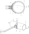
- the sensor assembly 1 is, as in Fig. 3a or 3b, in particular intended and set up to be placed on and connected to a wall of a pipe 2, which can be inserted, for example, by means of a flange connection, into the course of a pipeline supplying or discharging the fluid, to form a converter device for measuring at least one measured variable, for example a temperature, a density and/or a viscosity, of a flowing fluid.
- Fluid can be, for example, a gas, a liquid or a flowable dispersion.
- the sensor assembly 1 according to the invention or the converter device formed thereby can also be part of a measuring system - for example also vibronic - which is used to measure the aforementioned at least one measured variable, for example also vibronic.
- the sensor assembly 1 comprises a temperature sensor 11, a carrier element 12 for holding the same temperature sensor 11 and a coupling body 13 which thermally conductively couples the temperature sensor 11 to the carrier element 12.
- the temperature sensor 11 and the coupling body 13 are advantageously connected to one another in a materially bonded manner.
- the temperature sensor 11 is designed to detect a temperature at a temperature measuring point formed thereby and to convert it into a temperature measuring signal 81, namely an electrical measuring signal representing the measuring point temperature ⁇ 1, for example with an electrical signal voltage dependent on the same first measuring point temperature and/or an electrical signal current dependent on the same first measuring point temperature.
- the temperature sensor 11 of the sensor assembly according to the invention can, for example, be connected by means of a temperature-sensitive measuring resistor, for example a platinum measuring resistor, such as a Pt100, a Pt500 or a Pt1000.
- a temperature-sensitive measuring resistor for example a platinum measuring resistor, such as a Pt100, a Pt500 or a Pt1000.
- the temperature sensor can also be formed by means of a thermistor and/or a thermocouple.
- the temperature sensor can advantageously be a temperature sensor manufactured using thin-film technology, for example a platinum measuring resistor manufactured using thin-film technology, such as that offered by Innovative Sensor Technology IST AG, Ebnat-Kappel, CH, among others under the designation P0K1.520.4WB010.
- the temperature sensor 11 has a carrier 111, for example made of glass and/or ceramic, and at least one arranged on the same carrier 111, for example applied using thin-film technology and/or - as also in Fig. 2 indicated - at least in sections meandering, conductor track 112, e.g. made of platinum.
- the temperature sensor 11 can also, as in Fig.
- the protective layer 113 can, for example, consist at least partially of a glass, in particular a lead-free glass and/or a glass that conforms to EU Directive 2011/65/EU (ROHS 2).
- a metallization layer 114 can be provided on the side of the carrier 111 opposite the conductor track, as indicated.
- This metallization layer 114 which is applied using thin-film technology for example, can be used, not least in the case described above, in which the carrier 111 is made of ceramic or glass and the carrier element is made of a metal, to be able to solder the temperature sensor 11 to a metal body.
- the carrier element 12 of the sensor assembly 1 has a central segment 12a, a plate-shaped first end segment 12b adjoining a first end of the central segment 12a, and a second end segment 12c adjoining a plate-shaped second end of the central segment 12a, which is remote from the first end.
- the aforementioned sub-segments 12a of the carrier element 12 can - as in Fig. 1a or from a summary of the Fig. 1a, 1b and 2
- the carrier element 12 can be made of a metal, in particular a steel, and/or can be monolithic, for example, namely produced as a stamped and bent part.
- the carrier element 12 consists at least partially, in particular predominantly or completely, of a stainless steel, in particular an austenitic stainless steel.
- the coupling body 13 can, for example, be a block or a molded part made of metal and/or a plastic that conducts heat as well as possible.
- the coupling body 13 can also advantageously be created in-situ, namely only in the course of forming the sensor assembly, for example by soldering or gluing the temperature sensor 11 and the carrier element 12 together to form the coupling body 13.
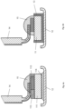
- the coupling body 13 can also be designed and arranged in such a way that it - as in Fig. 4b indicated - at least partially encloses the temperature sensor 11 or that the temperature sensor 11 is at least embedded in the coupling body 13.
- the temperature sensor 11 and the coupling body 13 are, as also Fig. 1a or 1b, are arranged together on a first surface 12+ of the carrier element 12.
- the coupling body 13 is also materially connected to the carrier element 12, in particular to its central segment 12a, to form a coupling body-to-carrier element connection zone.
- the surface 12+ of the carrier element 12 is flat at least in the region of the coupling body-to-carrier element connection zone and/or that the surface 12# of the carrier element 12 is flat at least in the region of the coupling body-to-carrier element connection zone, for example such that the surfaces 12+, 12# of the carrier element 12 are plane-parallel at least in the region of the coupling body-to-carrier element connection zone.
- the sensor assembly comprises, as in Fig. 1a and 1b indicated or evident from their combination, a pair of connecting wires 14 which are electrically connected to the temperature sensor 11, for example formed by means of copper wires and/or silver wires; which are arranged in particular in such a way that the connection points of the connecting wires 14 formed thereby with the conductor track 112 are each arranged on the aforementioned carrier 111.
- the connecting wires 14 can be bonded to the conductor track 112 of the carrier element 12 and the temperature sensor 11, for example, before the aforementioned joining of the carrier element 12 and the temperature sensor 11, possibly even during the manufacture of the temperature sensor 11.
- the sensor assembly further comprises a protective layer 15 which at least partially covers both the temperature sensor 11 and the aforementioned pair of connecting wires 14.
- the protective layer 15 can, for example, be bonded to the temperature sensor 11 and/or the connecting wires 14, or can consist at least partially of a plastic, such as a silicone and/or an epoxy resin.
- the protective layer 15 can be designed and positioned in such a way that the temperature sensor 11 and the pair of connecting wires 14 are covered within a common contact area, for example, including the aforementioned connection points of the connecting wires 14 with the conductor track 112.
- the sensor assembly can also be provided with a retaining clip 16 in order to improve its mechanical stability, which is integrally connected to the carrier element 12, but also surrounds the temperature sensor 11, for example holding the temperature sensor pressed against the carrier element.
- the retaining clip 16 can be made, for example, of a metal and/or the same material as the Carrier element 12 is manufactured and, as in Fig.5 shown schematically, be fixed to the central segment 12a of the support element 12, for example after the temperature sensor 11 has been attached thereto.
- the sensor assembly 1 is intended to be used as a component of a converter device serving to measure at least one measured variable, wherein the converter device comprises as a further component a tube 2 serving to guide the fluid.
- Said tube 2 has a lumen 22 surrounded by a, for example, metallic, wall 21 and is, as in Fig. 3a shown, at least in some areas hollow-cylindrical.
- the tube can be designed to guide the fluid to be measured in the aforementioned lumen, for example, namely, the fluid supplied or discharged via a pipe connected to it.
- the wall 22 of the tube 2 can advantageously consist at least partially, for example, predominantly or completely, of a stainless steel, e.g. an austenitic stainless steel.
- the tube 2 is further designed to guide the flowing fluid in the lumen 22 and to be allowed to vibrate during this process.
- the carrier element 12 or the sensor assembly 1 formed therewith is - as in Fig. 3a indicated - positioned on a hollow cylindrical, thus straight segment of the wall 22.
- the carrier element 12 - as in Fig. 3a indicated - at least in selected areas 100, it is materially connected to the wall 21 of the pipe 2, for example welded and/or soldered to the wall 21.
- the support element 12 and the wall 21 can also advantageously consist at least partially, for example predominantly or completely, of the same material, for example the same stainless steel.
- the carrier element 12 is designed and arranged on the pipe 2 in such a way that the middle segment 12a and/or the end segment 12b and/or the end segment 12c of the carrier element contact the wall 22 of the pipe; this in particular in such a way that the middle segment contacts the wall in the area of the aforementioned coupling body-to-carrier element connection zone or by forming a middle segment-to-pipe contact zone.
- the carrier element 12 can be the Pipe 2 attached sensor assembly 1 - as in Fig. 3a or 3b or from their combination it is immediately apparent - a different one from that in Fig.
- the carrier element 12 can be shaped in such a way that both the end segment 12b and the middle segment 12a of the carrier element as well as the end segment 12c and the middle segment 12a of the carrier element each enclose an angle of less than 180° and more than 90°, in particular of equal size.
- the middle segment 12a of the carrier element the wall of the pipe - as in Fig. 3b indicated - only tangentially contacted and/or that the end segment 12b and/or the end segment 12c contact the wall 22 over its surface.
- the end segment 12b of the carrier element 12 and the wall 21 of the pipe 2 are welded together, for example by means of resistance or spot welding, and/or the end segment 12c of the carrier element 12 and the wall 21 of the pipe 2 are welded together, in particular by means of resistance or spot welding; this in particular in such a way that the middle segment 12a of the carrier element 12 is not integrally connected to the wall of the pipe or that only the two aforementioned end segments 12b, 12c of the carrier element 12 are integrally connected to the wall 21 of the pipe 2.
- a thermally conductive paste can be applied at least between the middle segment of the carrier element and the wall of the pipe.
- the middle segment 12a and the wall 21, as in Fig.6 can also be connected to one another in a material-locking manner, for example by means of a soldered connection or by means of a thermally conductive adhesive 3.
- the converter device according to the invention can be manufactured very simply, for example, by positioning the sensor assembly provided on the pipe 2 provided in such a way that the end segment 12b is first placed on the wall 21 of the pipe 2 and is bonded there to the wall 2, for example by means of resistance welding, and then the - initially still free - end segment 12c is also placed accordingly on the wall 21 of the pipe 2 - in particular tightly or by forming the aforementioned middle segment-to-pipe contact zone - and is bonded there to the wall 2, for example also by means of resistance welding.
- a sensor assembly 1 can also advantageously be provided with an initially in its original, for example, one in Fig. 1a, 1b or 2 shown form corresponding to the initial shape left carrier element 12, wherein the in Fig. 3a or 3b final installation form is practically only brought about during the connection of sensor assembly 1 and pipe 2.
- the carrier element 12 in the sensor assembly according to the invention or the converter device formed therewith is designed such that a minimum bending stiffness EI 12a , which the middle segment 12a has at least in the area of the aforementioned coupling body-to-carrier element connection zone, is greater than a minimum bending stiffness EI 12 , which the carrier element 12 has as a whole, or that the same minimum bending stiffness EI 12 , of the middle segment 12a is greater than a minimum bending stiffness EI 12b , which the end segment 12b has, and/or than a minimum bending stiffness EI 12c , which the end segment 12c.
- the carrier element 12 can also be manually transferred from its initial shape to the aforementioned final installation shape during the final assembly of the sensor assembly 1 on the pipe 2, and that, on the other hand, the coupling body-to-carrier element connection zone, which is particularly critical for the long-term stability of the sensor assembly or the converter device formed thereby, is kept free of excessive mechanical stresses which damage the sensor assembly 1.
- the end segment 12b and/or the end segment 12c is designed to be plastically deformed, in particular bent, as a result of a bending force introduced therein at a distance from the middle segment 12a, or the middle segment 12a is designed not to be plastically deformed as a result of a bending force introduced into the end segment 12b and/or into the end segment 12c, namely end segment 12b or 12c, respectively.
- the inventive relations of the aforementioned bending stiffnesses EI 12 , EI 12a , EI 12b , EI 12 can - as in Fig. 2 shown schematically - can be produced in a very simple manner by means of material weakenings 12'12" specifically made on the carrier element, for example in the form of recesses, bores and/or elongated holes made accordingly in the carrier element.
Landscapes
- Physics & Mathematics (AREA)
- General Physics & Mathematics (AREA)
- Nonlinear Science (AREA)
- Measuring Temperature Or Quantity Of Heat (AREA)
- Measuring Volume Flow (AREA)
Claims (13)
- Appareil de transduction, comprenant :- un tube (2) comportant une lumière (22) entourée d'une paroi (21), en particulier d'une paroi métallique (22),- et un ensemble de capteurs (1), cetensemble de capteurs comprenant- un capteur de température (11), notamment un capteur de température fabriqué en particulier selon la technologie des couches minces ou formé au moyen d'au moins une résistance de mesure en platine ;- un élément porteur métallique (2), en particulier un élément porteur métallique monolithique et/ou en forme de pince (2), destiné à recevoir le capteur de température-- avec un segment central (12a), notamment en forme de plaque,-- avec un premier segment d'extrémité en forme de plaque (12b) adjacent à une première extrémité du segment central-- et avec un deuxième segment d'extrémité en forme de plaque (12c) attenant à une deuxième extrémité du segment central éloignée de la première extrémité ;- et un corps de couplage (13), en particulier au moins partiellement enveloppant et/ou métallique, qui relie par conduction thermique le capteur de température et l'élément porteur ;dans lequel le capteur de température (11) et le corps de couplage (13) sont reliés l'un à l'autre par une liaison matérielle et sont disposés ensemble sur une première surface (12+) de l'élément porteur (12),- et dans lequel le corps de couplage (13) est relié à l'élément porteur (12), en particulier à son segment central (12a), formant une zone de connexion entre le corps de couplage et le support ;- dans lequel l'élément porteur (12) de l'ensemble capteur (1) est disposé sur la surface (21+) de la paroi (21) du tube opposée à la lumière et est relié à ladite paroi (21) par une liaison matérielle, en particulier par soudure et/ou brasage,et dans lequel la plus petite rigidité de flexion EI12ad, que le segment central (12a) présente au moins dans la zone de connexion entre le corps de couplage et l'élément de support, est supérieure à la plus petite rigidité de flexion EI12, que l'élément de support (12) présente dans son ensemble, et/ou est supérieure à la plus petite rigidité de flexion EI12bd, que le premier segment d'extrémité (12b) présente, et/ou est supérieure à la plus petite rigidité de flexion EI12cd, que le deuxième segment d'extrémité (12c) présente.-- dans lequel l'élément porteur (12) est disposé sur un segment cylindrique creux de la paroi (21),-- et dans lequel l'élément porteur (12) entre en contact avec la paroi (21) du tube avec une deuxième surface (12#), en particulier plane, opposée à la première surface (12+) de l'élément porteur, au moins dans certaines zones ;
- Appareil transducteur selon l'une des revendications précédentes,- dans lequel le premier segment d'extrémité (12b) est conçu pour être déformé plastiquement, en particulier plié, sous l'effet d'une force de flexion introduite dans ce segment à une certaine distance du segment central (12a) ; et/ou- dans lequel le second segment d'extrémité (12c) est conçu pour être déformé plastiquement, en particulier plié, sous l'effet d'une force de flexion introduite à une certaine distance du segment central (12a) ; et/ou- dans lequel le segment central (12a) est configuré pour se déplacer dans le premier segment d'extrémité (12b) à la suite d'une
une force de flexion injectée déformant plastiquement ledit segment d'extrémité (12b) et/ou une force de flexion déformant plastiquement ledit segment d'extrémité (12c) introduite dans le second segment d'extrémité (12c) ; et/ou- dans lequel le premier segment d'extrémité (12b) et le second segment d'extrémité (12c) sont conçus pour être déformés, en particulier plastiquement, sous l'effet d'une force de flexion introduite à une certaine distance du segment central (12a),en particulier plié, en particulier tel que le premier segment d'extrémité (12b) et le segment central (12a) et le deuxième segment d'extrémité (12c) et le segment central (12a) forment chacun un angle V, en particulier de même taille, inférieur à 180° et supérieur à 90° et/ou tel que le segment d'extrémité (12c) et le segment central (12a) forment chacun un angle V de même taille.la première surface est convexe dans une zone s'étendant du premier segment d'extrémité au second segment d'extrémité ; et/oudans lequel l'élément porteur est constitué au moins en partie, en particulier de façon prédominante ou complète, d'un acier inoxydable, en particulier d'un acier inoxydable austénitique. - Appareil transducteur selon l'une des revendications précédentes, dans lequel le capteur de température (11) comporte un support (111), notamment en verre et/ou en céramique, et au moins une piste conductrice (112), notamment en platine, disposée sur le support (111), notamment appliquée selon la technologie des couches minces et/ou serpentant au moins par sections.
- Appareil transducteur selon la revendication précédente,- dans lequel le capteur de température (11) comporte une couche protectrice (113) recouvrant au moins partiellement la piste conductrice (112), notamment constituée au moins en partie d'un verre sans plomb et/ou d'un verre conforme à la directive européenne 2011/65/UE (ROHS 2) ; et/ou- dans lequel le capteur de température possède une couche de métallisation, notamment appliquée à l'aide de la technologie des couches minces, sur un côté du support (11) qui ne supporte pas la au moins une piste conductrice, notamment en face de la piste conductrice.
- Dispositif transducteur selon l'une quelconque des revendications précédentes, comprenant en outre : un transducteur relié au capteur de température par une paire de fils de connexion (14) connectés électriquement, formés en particulier au moyen de fils de cuivre et/ou de fils d'argent.
- Dispositif transducteur selon la revendication précédente, comprenant en outre : un fil de connexion (14) reliant à la fois le capteur de température (11) et la paire de fils de connexion (14), en particulier dans une zone de contact commune, dans chaque cas au moins partiellement recouvert, en particulier au moins partiellement constitué d'une couche protectrice en plastique (15), en particulier constituée d'une silicone et/ou d'une résine époxy.
- Appareil transducteur selon l'une des revendications précédentes, comprenant en outre : un capteur de température qui est relié à l'élément porteur, en particulier à son élément central, par une liaison matérielle, mais qui comporte néanmoins le capteur de température
pince de maintien (16), en particulier en métal, qui maintient le capteur de température pressé contre l'élément porteur. - Appareil transducteur selon l'une des revendications précédentes,- dans lequel le capteur de température (11) est conçu pour détecter une température à un point de mesure de la température formé avec lui et pour la convertir en un signal de mesure de la température (θ 1), à savoir un signal de mesure électrique représentant la température du point de mesure (ϑ 1), en particulier avec un signal électrique du même point de mesure de la température.
un signal électrique de tension dépendant de la température du premier point de mesure et/ou un signal électrique de courant dépendant de la même température du premier point de mesure ; et/ou- dans lequel le capteur de température (11) est constitué d'une résistance de mesure en platine ; et/ou- dans lequel le capteur de température est constitué d'une thermistance ; et/ou- le capteur de température étant constitué d'un thermocouple. - Appareil transducteur selon l'une des revendications précédentes,- dans lequel le tube est adapté pour transporter un fluide, par exemple un gaz, un liquide ou une dispersion fluide, circulant au moins de manière intermittente dans sa lumière ; et/ou- dans lequel le tube est adapté pour transporter dans sa lumière un fluide, par exemple un gaz, un liquide ou une dispersion fluide, s'écoulant au moins de manière intermittente, tout en étantvibré ; et/ou- dans lequel la deuxième surface (12#) de l'élément porteur est concave dans une région s'étendant de son premier segment d'extrémité (12b) à son deuxième segment d'extrémité (12c) ; et/ou- dans lequel le premier segment d'extrémité (12b) et le segment central (12a) de l'élément porteur ainsi que le deuxième segment d'extrémité (12c) et le segment central (12a) de l'élément porteur forment chacun un angle, en particulier de même taille, inférieur à 180° et supérieur à 90° ; et/ou- dans lequel la première surface (12+) de l'élément porteur est convexe dans une zone s'étendant de son premier segment d'extrémité (12b) à son second segment d'extrémité (12c).
- Appareil transducteur selon l'une des revendications précédentes,- dans lequel l'élément porteur, en particulier son segment central et/ou son premier segment d'extrémité et/ou son second segment d'extrémité, est en contact avec la paroi du tube ; et/ou- la paroi du tube étant constituée au moins en partie, en particulier de façon prédominante ou complète, de est constituée d'un acier inoxydable, en particulier d'un acier inoxydable austénitique ; et/ou- dans lequel l'élément de support et la paroi du tube sont constitués au moins en partie, en particulier de façon prédominante ou complète, du même matériau ; et/ou- dans lequel le premier segment d'extrémité de l'élément de support et la paroi du tube sont soudés l'un à l'autre, notamment au moyen d'une soudure par résistance ; et/ou- dans lequel le deuxième segment d'extrémité de l'élément de support et la paroi du tube sont soudés ensemble, en particulier au moyen d'une soudure par résistance ; et/ou- dans lequel l'élément porteur a une forme de pince ; et/ou- dans lequel la première surface de l'élément porteur est plate au moins
dans la zone de connexion entre le corps de couplage et l'élément
porteur ; et/ou- dans lequel le segment central de l'élément de support entre en contact avec la paroi du tube dans la zone de connexion entre le corps de couplage et l'élément de
support ; et/ou- le segment central de l'élément de support n'entrant en contact que de manière tangentielle avec la paroi du tube. - Appareil transducteur selon l'une des revendications précédentes,- dans lequel le segment central de l'élément de support entre en contact avec la paroi du tube pour former une zone de contact entre le segment central et le tube ; et/ou- dans lequel une pâte thermoconductrice et/ou un adhésif thermoconducteur est appliqué au moins entre le segment central de l'élément porteur et la paroi du tube ; et/ou- le segment central de l'élément de support et la paroi du tube sont soudés l'un à l'autre ; et/ou- dans lequel seuls les premier et deuxième segments d'extrémité de l'élément de support,mais pas son segment central, sont reliés à la paroi du tube par une liaison matérielle ;
et/ou- le segment central de l'élément de support n'est pas relié à la paroi du tube par une liaison matérielle. - Système de mesure pour mesurer au moins un mesurande, en particulier une température, une densité et/ou une viscosité, d'un fluide en écoulement, en particulier un gaz, un liquide ou une dispersion fluide, lequel système de mesure comprend :- un dispositif transducteur selon l'une des revendications précédentes pour guider le fluide ;- et une unité électronique de mesure et d'exploitation (ME) reliée électriquement au capteur de température, notamment au moyen d'un microprocesseur.
- Procédé de fabrication d'un dispositif de transduction selon l'une quelconque des revendications précédentes, comprenant :- fournir l'ensemble du capteur ;- préparer le tuyau ;- placer le premier segment d'extrémité de l'élément de support contre la paroi du tuyau ;- liaison par verrouillage du matériau du premier segment d'extrémité de l'élément de support à la paroi du tuyau,
notamment par soudage par résistance ;- placer le deuxième segment d'extrémité de l'élément de support contre la paroi du tuyau ;- ainsi que le collage matériel du deuxième segment d'extrémité de l'élément de support à la paroi du tube, notamment par soudage par résistance.
Applications Claiming Priority (2)
| Application Number | Priority Date | Filing Date | Title |
|---|---|---|---|
| DE102017118109.1A DE102017118109A1 (de) | 2017-08-09 | 2017-08-09 | Sensorbaugruppe |
| PCT/EP2018/068898 WO2019029942A1 (fr) | 2017-08-09 | 2018-07-12 | Module de détection |
Publications (2)
| Publication Number | Publication Date |
|---|---|
| EP3665456A1 EP3665456A1 (fr) | 2020-06-17 |
| EP3665456B1 true EP3665456B1 (fr) | 2024-09-04 |
Family
ID=62916665
Family Applications (1)
| Application Number | Title | Priority Date | Filing Date |
|---|---|---|---|
| EP18740801.8A Active EP3665456B1 (fr) | 2017-08-09 | 2018-07-12 | Dispositif transducteur avec un ensemble de capteur et procédé pour sa fabrication |
Country Status (5)
| Country | Link |
|---|---|
| US (1) | US11428578B2 (fr) |
| EP (1) | EP3665456B1 (fr) |
| CN (1) | CN110998263A (fr) |
| DE (1) | DE102017118109A1 (fr) |
| WO (1) | WO2019029942A1 (fr) |
Families Citing this family (3)
| Publication number | Priority date | Publication date | Assignee | Title |
|---|---|---|---|---|
| CN218035396U (zh) * | 2021-04-30 | 2022-12-13 | 浙江盾安禾田金属有限公司 | 空调感温头安装结构及空调器 |
| CN113384156B (zh) * | 2021-05-21 | 2025-08-29 | 孝感华工高理电子有限公司 | 一种发热盘温控组件及加热装置及方法 |
| NO20230433A1 (en) * | 2023-04-21 | 2024-10-22 | Clampon As | An apparatus and a method for determing the temperature of fluids contained in a pipe or a vessel |
Citations (1)
| Publication number | Priority date | Publication date | Assignee | Title |
|---|---|---|---|---|
| EP0171904A1 (fr) * | 1984-07-02 | 1986-02-19 | Philip F. Finney | Ensemble de thermocouple |
Family Cites Families (31)
| Publication number | Priority date | Publication date | Assignee | Title |
|---|---|---|---|---|
| DE3632800A1 (de) | 1986-09-26 | 1988-04-07 | Flowtec Ag | Nach dem coriolisprinzip arbeitendes massendurchflussmessgeraet |
| DE4224379C2 (de) | 1992-07-06 | 1998-05-20 | Krohne Messtechnik Kg | Massendurchflußmeßgerät |
| DE29621433U1 (de) * | 1996-12-10 | 1998-04-16 | Landis & Gyr Tech Innovat | Temperaturfühler |
| US6311136B1 (en) | 1997-11-26 | 2001-10-30 | Invensys Systems, Inc. | Digital flowmeter |
| US6327915B1 (en) | 1999-06-30 | 2001-12-11 | Micro Motion, Inc. | Straight tube Coriolis flowmeter |
| US6550962B1 (en) * | 2000-09-28 | 2003-04-22 | Therm-O-Disc, Incorporated | Temperature monitoring assembly having a thermostatic control with mounting clip |
| DE10210772C1 (de) | 2002-03-12 | 2003-06-26 | Heraeus Sensor Nite Gmbh | Temperatursensor |
| US6814486B2 (en) * | 2002-08-09 | 2004-11-09 | Advanced Thermal Products, Inc. | Return bend temperature sensor |
| US7040179B2 (en) | 2002-12-06 | 2006-05-09 | Endress+ Hauser Flowtec Ag | Process meter |
| DE102005061703A1 (de) * | 2005-12-21 | 2007-07-05 | Innovative Sensor Technology Ist Ag | Vorrichtung zur Bestimmung und/oder Überwachung einer Prozessgrösse und Verfahren zur Herstellung einer entsprechenden Sensoreinheit |
| US7549319B2 (en) | 2006-11-16 | 2009-06-23 | Halliburton Energy Services, Inc. | High pressure resonant vibrating-tube densitometer |
| DE102007035997A1 (de) | 2007-07-30 | 2009-02-05 | Innovative Sensor Technology Ist Ag | Vorrichtung zur Bestimmung und/oder Überwachung einer Prozessgröße |
| US7597472B2 (en) * | 2008-01-25 | 2009-10-06 | Pacific Controls Co., Ltd. | Temperature sensor assembly having bracket |
| JP5323928B2 (ja) | 2008-05-01 | 2013-10-23 | マイクロ モーション インコーポレイテッド | 流量計のパラメータの異常から診断を行う方法 |
| US8336396B2 (en) | 2009-03-11 | 2012-12-25 | Endress + Hauser Flowtec Ag | Measuring transducer of vibration-type, as well as an in-line measuring device having such a measuring transducer |
| DE102009046839A1 (de) | 2009-11-18 | 2011-05-19 | Endress + Hauser Flowtec Ag | Meßsystem mit einer zwei parallel durchströmte Meßrohre aufweisenden Rohranordnung sowie Verfahren zu deren Überwachung |
| US8181533B2 (en) | 2010-01-06 | 2012-05-22 | Daniel Measurement And Control, Inc. | Ultrasonic flow meter and transducer assembly with isolated transformer capsule |
| MX2013002141A (es) | 2010-09-09 | 2013-04-03 | Micro Motion Inc | Compensacion de tension termica en un medidor de flujo vibratorio de tubo curveado. |
| KR101569887B1 (ko) | 2010-11-16 | 2015-11-27 | 마이크로 모우션, 인코포레이티드 | 다중 온도 센서 시스템 |
| CN103370605B (zh) | 2011-02-23 | 2015-08-19 | 微动公司 | 振动流量计和用于测量温度的方法 |
| US9120286B2 (en) * | 2011-03-31 | 2015-09-01 | Fos Llc | Fiber optic sensor thermally matched support tubes for distributed fiber optic sensing |
| DE102011080894A1 (de) | 2011-08-12 | 2013-02-14 | Endress + Hauser Flowtec Ag | Sensor-Modul zum Messen und/oder Überwachen von Parametern von in Rohrleitungen strömenden Medien sowie damit gebildetes Meßsystem |
| DE102012204898A1 (de) * | 2012-03-27 | 2013-10-02 | Klaus Schirmer | Temperatursensor |
| DE102012017797B4 (de) | 2012-09-10 | 2014-09-18 | Krohne Ag | Durchflussmessgerät |
| US20140161151A1 (en) * | 2012-12-12 | 2014-06-12 | John Proctor | Line & pipe flexible temperature sensor assembly |
| DE102014103427A1 (de) | 2014-03-13 | 2015-09-17 | Endress + Hauser Flowtec Ag | Wandlervorrichtung sowie damit gebildetes Meßsystem |
| DE102014116658B4 (de) | 2014-11-14 | 2016-06-23 | Krohne Ag | Vorrichtung zur Temperaturbestimmung sowie Messanordnung zur Bestimmung des Durchflusses |
| CN204373800U (zh) | 2015-01-19 | 2015-06-03 | 大连理工大学 | 一种测量高温管道外壁温度的夹具装置 |
| US10101216B2 (en) * | 2015-03-16 | 2018-10-16 | Miclau-S.R.I. Inc. | Conduit for the reomovable positioning of temperature sensors in a water heater and method |
| DE102015114314A1 (de) | 2015-08-28 | 2017-03-02 | Innovative Sensor Technology Ist Ag | Verfahren zur Herstellung eines Temperatursensors |
| CN205120268U (zh) * | 2015-11-13 | 2016-03-30 | 孔浩 | 一种ntc温度传感器 |
-
2017
- 2017-08-09 DE DE102017118109.1A patent/DE102017118109A1/de active Pending
-
2018
- 2018-07-12 CN CN201880051576.7A patent/CN110998263A/zh active Pending
- 2018-07-12 US US16/637,572 patent/US11428578B2/en active Active
- 2018-07-12 EP EP18740801.8A patent/EP3665456B1/fr active Active
- 2018-07-12 WO PCT/EP2018/068898 patent/WO2019029942A1/fr not_active Ceased
Patent Citations (1)
| Publication number | Priority date | Publication date | Assignee | Title |
|---|---|---|---|---|
| EP0171904A1 (fr) * | 1984-07-02 | 1986-02-19 | Philip F. Finney | Ensemble de thermocouple |
Also Published As
| Publication number | Publication date |
|---|---|
| DE102017118109A1 (de) | 2019-02-14 |
| CN110998263A (zh) | 2020-04-10 |
| WO2019029942A1 (fr) | 2019-02-14 |
| US11428578B2 (en) | 2022-08-30 |
| EP3665456A1 (fr) | 2020-06-17 |
| US20200256738A1 (en) | 2020-08-13 |
Similar Documents
| Publication | Publication Date | Title |
|---|---|---|
| EP3665456B1 (fr) | Dispositif transducteur avec un ensemble de capteur et procédé pour sa fabrication | |
| DE19530413C1 (de) | Verfahren zur Befestigung und Kontaktierung von Widerstandselementen für Heißfilmanemometer sowie Sensoranordnung | |
| DE102012204898A1 (de) | Temperatursensor | |
| EP2591318B1 (fr) | Capteur de mesure de débitmètre thermique pour déterminer le débit d'un milieu dans un tube de mesure et procédé de production dudit capteur de mesure | |
| EP0905493B1 (fr) | Capteur électrique, en particulier capteur de température, avec plaque à circuit imprimé | |
| EP0149416A2 (fr) | Thermomètre pour mesurer la température dans des milieux de faible convection | |
| EP1255972B2 (fr) | Sonde de température et procédé pour la mise en contact d'une sonde de température | |
| EP3612806A1 (fr) | Capteur de température à contact | |
| DE10315519B4 (de) | Temperaturerfassungselement und mit demselben versehenes Schaltungssubstrat | |
| WO2018134085A1 (fr) | Capteur | |
| DE3620246C2 (de) | Temperaturfühler | |
| EP4048992B1 (fr) | Procédé pour relier un dispositif à un élément support | |
| DE102015221458B3 (de) | Verfahren zur Herstellung eines Messgeräts mit einer Sensorspitze | |
| EP4078101B1 (fr) | Dispositif de mesure | |
| DE19802296A1 (de) | Verfahren und Temperaturfühler zur Messung von Oberflächentemperaturen | |
| WO2019174968A1 (fr) | Élément capteur de température | |
| DE10237946B4 (de) | Füllstandssensor zur Verwendung bei einer Vorrichtung zum elektrischen Messen der Füllstandshöhe einer Flüssigkeit in einem Behälter sowie Verfahren zur Einstellung des Nullpunktes des Anzeigesignals für wenigstens eine Anzeigevorrichtung dieser Vorrichtung | |
| DE102022131916A1 (de) | Elektrisches oder elektronisches Bauelement und Verfahren zu dessen Herstellung | |
| DE2059879B2 (de) | Thermoelektrische Sonde zur Überwachung der Strömung eines Mediums und Verfahren zu deren Herstellung | |
| WO2021197722A1 (fr) | Liaison soudée électrique, capteur pourvu d'une liaison soudée et procédé de fabrication | |
| DE102023124584A1 (de) | Sensoranordnung und Verfahren zur Herstellung einer Sensoranordnung | |
| DE3049056A1 (de) | Temperaturfuehler | |
| DE102023208039A1 (de) | Anordnung und Verfahren zu Strommessung | |
| DE102023108929A1 (de) | Temperatursensor und Durchflussmessgerät | |
| DE19946533C2 (de) | Sensor zur Messung der Strömungsgeschwindigkeit von Gasen und Verfahren zu dessen Herstellung |
Legal Events
| Date | Code | Title | Description |
|---|---|---|---|
| STAA | Information on the status of an ep patent application or granted ep patent |
Free format text: STATUS: UNKNOWN |
|
| STAA | Information on the status of an ep patent application or granted ep patent |
Free format text: STATUS: THE INTERNATIONAL PUBLICATION HAS BEEN MADE |
|
| PUAI | Public reference made under article 153(3) epc to a published international application that has entered the european phase |
Free format text: ORIGINAL CODE: 0009012 |
|
| STAA | Information on the status of an ep patent application or granted ep patent |
Free format text: STATUS: REQUEST FOR EXAMINATION WAS MADE |
|
| 17P | Request for examination filed |
Effective date: 20200123 |
|
| AK | Designated contracting states |
Kind code of ref document: A1 Designated state(s): AL AT BE BG CH CY CZ DE DK EE ES FI FR GB GR HR HU IE IS IT LI LT LU LV MC MK MT NL NO PL PT RO RS SE SI SK SM TR |
|
| AX | Request for extension of the european patent |
Extension state: BA ME |
|
| DAV | Request for validation of the european patent (deleted) | ||
| DAX | Request for extension of the european patent (deleted) | ||
| STAA | Information on the status of an ep patent application or granted ep patent |
Free format text: STATUS: EXAMINATION IS IN PROGRESS |
|
| 17Q | First examination report despatched |
Effective date: 20220218 |
|
| REG | Reference to a national code |
Ref country code: DE Ref legal event code: R079 Ref country code: DE Ref legal event code: R079 Ref document number: 502018015091 Country of ref document: DE Free format text: PREVIOUS MAIN CLASS: G01K0001140000 Ipc: G01K0001143000 |
|
| GRAP | Despatch of communication of intention to grant a patent |
Free format text: ORIGINAL CODE: EPIDOSNIGR1 |
|
| STAA | Information on the status of an ep patent application or granted ep patent |
Free format text: STATUS: GRANT OF PATENT IS INTENDED |
|
| GRAJ | Information related to disapproval of communication of intention to grant by the applicant or resumption of examination proceedings by the epo deleted |
Free format text: ORIGINAL CODE: EPIDOSDIGR1 |
|
| STAA | Information on the status of an ep patent application or granted ep patent |
Free format text: STATUS: EXAMINATION IS IN PROGRESS |
|
| RIC1 | Information provided on ipc code assigned before grant |
Ipc: G01K 13/02 20060101ALI20240213BHEP Ipc: G01K 1/143 20210101AFI20240213BHEP |
|
| GRAP | Despatch of communication of intention to grant a patent |
Free format text: ORIGINAL CODE: EPIDOSNIGR1 |
|
| STAA | Information on the status of an ep patent application or granted ep patent |
Free format text: STATUS: GRANT OF PATENT IS INTENDED |
|
| INTG | Intention to grant announced |
Effective date: 20240305 |
|
| INTC | Intention to grant announced (deleted) | ||
| INTG | Intention to grant announced |
Effective date: 20240403 |
|
| GRAS | Grant fee paid |
Free format text: ORIGINAL CODE: EPIDOSNIGR3 |
|
| GRAA | (expected) grant |
Free format text: ORIGINAL CODE: 0009210 |
|
| STAA | Information on the status of an ep patent application or granted ep patent |
Free format text: STATUS: THE PATENT HAS BEEN GRANTED |
|
| AK | Designated contracting states |
Kind code of ref document: B1 Designated state(s): AL AT BE BG CH CY CZ DE DK EE ES FI FR GB GR HR HU IE IS IT LI LT LU LV MC MK MT NL NO PL PT RO RS SE SI SK SM TR |
|
| REG | Reference to a national code |
Ref country code: GB Ref legal event code: FG4D Free format text: NOT ENGLISH |
|
| REG | Reference to a national code |
Ref country code: CH Ref legal event code: EP |
|
| REG | Reference to a national code |
Ref country code: IE Ref legal event code: FG4D Free format text: LANGUAGE OF EP DOCUMENT: GERMAN |
|
| REG | Reference to a national code |
Ref country code: DE Ref legal event code: R096 Ref document number: 502018015091 Country of ref document: DE |
|
| P01 | Opt-out of the competence of the unified patent court (upc) registered |
Free format text: CASE NUMBER: APP_48882/2024 Effective date: 20240827 |
|
| REG | Reference to a national code |
Ref country code: NL Ref legal event code: FP |
|
| REG | Reference to a national code |
Ref country code: LT Ref legal event code: MG9D |
|
| PG25 | Lapsed in a contracting state [announced via postgrant information from national office to epo] |
Ref country code: NO Free format text: LAPSE BECAUSE OF FAILURE TO SUBMIT A TRANSLATION OF THE DESCRIPTION OR TO PAY THE FEE WITHIN THE PRESCRIBED TIME-LIMIT Effective date: 20241204 |
|
| PG25 | Lapsed in a contracting state [announced via postgrant information from national office to epo] |
Ref country code: FI Free format text: LAPSE BECAUSE OF FAILURE TO SUBMIT A TRANSLATION OF THE DESCRIPTION OR TO PAY THE FEE WITHIN THE PRESCRIBED TIME-LIMIT Effective date: 20240904 Ref country code: GR Free format text: LAPSE BECAUSE OF FAILURE TO SUBMIT A TRANSLATION OF THE DESCRIPTION OR TO PAY THE FEE WITHIN THE PRESCRIBED TIME-LIMIT Effective date: 20241205 Ref country code: PL Free format text: LAPSE BECAUSE OF FAILURE TO SUBMIT A TRANSLATION OF THE DESCRIPTION OR TO PAY THE FEE WITHIN THE PRESCRIBED TIME-LIMIT Effective date: 20240904 |
|
| PG25 | Lapsed in a contracting state [announced via postgrant information from national office to epo] |
Ref country code: BG Free format text: LAPSE BECAUSE OF FAILURE TO SUBMIT A TRANSLATION OF THE DESCRIPTION OR TO PAY THE FEE WITHIN THE PRESCRIBED TIME-LIMIT Effective date: 20240904 |
|
| PG25 | Lapsed in a contracting state [announced via postgrant information from national office to epo] |
Ref country code: LV Free format text: LAPSE BECAUSE OF FAILURE TO SUBMIT A TRANSLATION OF THE DESCRIPTION OR TO PAY THE FEE WITHIN THE PRESCRIBED TIME-LIMIT Effective date: 20240904 |
|
| PG25 | Lapsed in a contracting state [announced via postgrant information from national office to epo] |
Ref country code: HR Free format text: LAPSE BECAUSE OF FAILURE TO SUBMIT A TRANSLATION OF THE DESCRIPTION OR TO PAY THE FEE WITHIN THE PRESCRIBED TIME-LIMIT Effective date: 20240904 |
|
| PG25 | Lapsed in a contracting state [announced via postgrant information from national office to epo] |
Ref country code: ES Free format text: LAPSE BECAUSE OF FAILURE TO SUBMIT A TRANSLATION OF THE DESCRIPTION OR TO PAY THE FEE WITHIN THE PRESCRIBED TIME-LIMIT Effective date: 20240904 Ref country code: RS Free format text: LAPSE BECAUSE OF FAILURE TO SUBMIT A TRANSLATION OF THE DESCRIPTION OR TO PAY THE FEE WITHIN THE PRESCRIBED TIME-LIMIT Effective date: 20241204 |
|
| PG25 | Lapsed in a contracting state [announced via postgrant information from national office to epo] |
Ref country code: RS Free format text: LAPSE BECAUSE OF FAILURE TO SUBMIT A TRANSLATION OF THE DESCRIPTION OR TO PAY THE FEE WITHIN THE PRESCRIBED TIME-LIMIT Effective date: 20241204 Ref country code: PL Free format text: LAPSE BECAUSE OF FAILURE TO SUBMIT A TRANSLATION OF THE DESCRIPTION OR TO PAY THE FEE WITHIN THE PRESCRIBED TIME-LIMIT Effective date: 20240904 Ref country code: NO Free format text: LAPSE BECAUSE OF FAILURE TO SUBMIT A TRANSLATION OF THE DESCRIPTION OR TO PAY THE FEE WITHIN THE PRESCRIBED TIME-LIMIT Effective date: 20241204 Ref country code: LV Free format text: LAPSE BECAUSE OF FAILURE TO SUBMIT A TRANSLATION OF THE DESCRIPTION OR TO PAY THE FEE WITHIN THE PRESCRIBED TIME-LIMIT Effective date: 20240904 Ref country code: HR Free format text: LAPSE BECAUSE OF FAILURE TO SUBMIT A TRANSLATION OF THE DESCRIPTION OR TO PAY THE FEE WITHIN THE PRESCRIBED TIME-LIMIT Effective date: 20240904 Ref country code: GR Free format text: LAPSE BECAUSE OF FAILURE TO SUBMIT A TRANSLATION OF THE DESCRIPTION OR TO PAY THE FEE WITHIN THE PRESCRIBED TIME-LIMIT Effective date: 20241205 Ref country code: FI Free format text: LAPSE BECAUSE OF FAILURE TO SUBMIT A TRANSLATION OF THE DESCRIPTION OR TO PAY THE FEE WITHIN THE PRESCRIBED TIME-LIMIT Effective date: 20240904 Ref country code: ES Free format text: LAPSE BECAUSE OF FAILURE TO SUBMIT A TRANSLATION OF THE DESCRIPTION OR TO PAY THE FEE WITHIN THE PRESCRIBED TIME-LIMIT Effective date: 20240904 Ref country code: BG Free format text: LAPSE BECAUSE OF FAILURE TO SUBMIT A TRANSLATION OF THE DESCRIPTION OR TO PAY THE FEE WITHIN THE PRESCRIBED TIME-LIMIT Effective date: 20240904 |
|
| PG25 | Lapsed in a contracting state [announced via postgrant information from national office to epo] |
Ref country code: PT Free format text: LAPSE BECAUSE OF FAILURE TO SUBMIT A TRANSLATION OF THE DESCRIPTION OR TO PAY THE FEE WITHIN THE PRESCRIBED TIME-LIMIT Effective date: 20250106 Ref country code: IS Free format text: LAPSE BECAUSE OF FAILURE TO SUBMIT A TRANSLATION OF THE DESCRIPTION OR TO PAY THE FEE WITHIN THE PRESCRIBED TIME-LIMIT Effective date: 20250104 |
|
| PG25 | Lapsed in a contracting state [announced via postgrant information from national office to epo] |
Ref country code: RO Free format text: LAPSE BECAUSE OF FAILURE TO SUBMIT A TRANSLATION OF THE DESCRIPTION OR TO PAY THE FEE WITHIN THE PRESCRIBED TIME-LIMIT Effective date: 20240904 Ref country code: SM Free format text: LAPSE BECAUSE OF FAILURE TO SUBMIT A TRANSLATION OF THE DESCRIPTION OR TO PAY THE FEE WITHIN THE PRESCRIBED TIME-LIMIT Effective date: 20240904 |
|
| PG25 | Lapsed in a contracting state [announced via postgrant information from national office to epo] |
Ref country code: EE Free format text: LAPSE BECAUSE OF FAILURE TO SUBMIT A TRANSLATION OF THE DESCRIPTION OR TO PAY THE FEE WITHIN THE PRESCRIBED TIME-LIMIT Effective date: 20240904 |
|
| PG25 | Lapsed in a contracting state [announced via postgrant information from national office to epo] |
Ref country code: CZ Free format text: LAPSE BECAUSE OF FAILURE TO SUBMIT A TRANSLATION OF THE DESCRIPTION OR TO PAY THE FEE WITHIN THE PRESCRIBED TIME-LIMIT Effective date: 20240904 |
|
| PG25 | Lapsed in a contracting state [announced via postgrant information from national office to epo] |
Ref country code: IT Free format text: LAPSE BECAUSE OF FAILURE TO SUBMIT A TRANSLATION OF THE DESCRIPTION OR TO PAY THE FEE WITHIN THE PRESCRIBED TIME-LIMIT Effective date: 20240904 Ref country code: SK Free format text: LAPSE BECAUSE OF FAILURE TO SUBMIT A TRANSLATION OF THE DESCRIPTION OR TO PAY THE FEE WITHIN THE PRESCRIBED TIME-LIMIT Effective date: 20240904 |
|
| REG | Reference to a national code |
Ref country code: DE Ref legal event code: R097 Ref document number: 502018015091 Country of ref document: DE |
|
| PG25 | Lapsed in a contracting state [announced via postgrant information from national office to epo] |
Ref country code: DK Free format text: LAPSE BECAUSE OF FAILURE TO SUBMIT A TRANSLATION OF THE DESCRIPTION OR TO PAY THE FEE WITHIN THE PRESCRIBED TIME-LIMIT Effective date: 20240904 |
|
| PLBE | No opposition filed within time limit |
Free format text: ORIGINAL CODE: 0009261 |
|
| STAA | Information on the status of an ep patent application or granted ep patent |
Free format text: STATUS: NO OPPOSITION FILED WITHIN TIME LIMIT |
|
| 26N | No opposition filed |
Effective date: 20250605 |
|
| PGFP | Annual fee paid to national office [announced via postgrant information from national office to epo] |
Ref country code: NL Payment date: 20250721 Year of fee payment: 8 |
|
| PG25 | Lapsed in a contracting state [announced via postgrant information from national office to epo] |
Ref country code: SE Free format text: LAPSE BECAUSE OF FAILURE TO SUBMIT A TRANSLATION OF THE DESCRIPTION OR TO PAY THE FEE WITHIN THE PRESCRIBED TIME-LIMIT Effective date: 20240904 |
|
| PGFP | Annual fee paid to national office [announced via postgrant information from national office to epo] |
Ref country code: DE Payment date: 20250722 Year of fee payment: 8 |
|
| PGFP | Annual fee paid to national office [announced via postgrant information from national office to epo] |
Ref country code: GB Payment date: 20250722 Year of fee payment: 8 |
|
| PGFP | Annual fee paid to national office [announced via postgrant information from national office to epo] |
Ref country code: FR Payment date: 20250725 Year of fee payment: 8 |
|
| REG | Reference to a national code |
Ref country code: CH Ref legal event code: H13 Free format text: ST27 STATUS EVENT CODE: U-0-0-H10-H13 (AS PROVIDED BY THE NATIONAL OFFICE) Effective date: 20260224 |
|
| PG25 | Lapsed in a contracting state [announced via postgrant information from national office to epo] |
Ref country code: LU Free format text: LAPSE BECAUSE OF NON-PAYMENT OF DUE FEES Effective date: 20250712 |
|
| REG | Reference to a national code |
Ref country code: BE Ref legal event code: MM Effective date: 20250731 |
|
| PG25 | Lapsed in a contracting state [announced via postgrant information from national office to epo] |
Ref country code: BE Free format text: LAPSE BECAUSE OF NON-PAYMENT OF DUE FEES Effective date: 20250731 |
|
| PG25 | Lapsed in a contracting state [announced via postgrant information from national office to epo] |
Ref country code: CH Free format text: LAPSE BECAUSE OF NON-PAYMENT OF DUE FEES Effective date: 20250731 |