EP3665655B1 - Volumetrische darstellung von volumetrischen bilddaten mit interaktiver segmentierung - Google Patents
Volumetrische darstellung von volumetrischen bilddaten mit interaktiver segmentierung Download PDFInfo
- Publication number
- EP3665655B1 EP3665655B1 EP18743822.1A EP18743822A EP3665655B1 EP 3665655 B1 EP3665655 B1 EP 3665655B1 EP 18743822 A EP18743822 A EP 18743822A EP 3665655 B1 EP3665655 B1 EP 3665655B1
- Authority
- EP
- European Patent Office
- Prior art keywords
- volume
- sub
- user
- image data
- image
- Prior art date
- Legal status (The legal status is an assumption and is not a legal conclusion. Google has not performed a legal analysis and makes no representation as to the accuracy of the status listed.)
- Active
Links
Images


Classifications
-
- G—PHYSICS
- G06—COMPUTING OR CALCULATING; COUNTING
- G06T—IMAGE DATA PROCESSING OR GENERATION, IN GENERAL
- G06T15/00—Three-dimensional [3D] image rendering
- G06T15/08—Volume rendering
-
- G—PHYSICS
- G06—COMPUTING OR CALCULATING; COUNTING
- G06F—ELECTRIC DIGITAL DATA PROCESSING
- G06F3/00—Input arrangements for transferring data to be processed into a form capable of being handled by the computer; Output arrangements for transferring data from processing unit to output unit, e.g. interface arrangements
- G06F3/01—Input arrangements or combined input and output arrangements for interaction between user and computer
- G06F3/048—Interaction techniques based on graphical user interfaces [GUI]
- G06F3/0481—Interaction techniques based on graphical user interfaces [GUI] based on specific properties of the displayed interaction object or a metaphor-based environment, e.g. interaction with desktop elements like windows or icons, or assisted by a cursor's changing behaviour or appearance
- G06F3/04815—Interaction with a metaphor-based environment or interaction object displayed as three-dimensional [3D], e.g. changing the user viewpoint with respect to the environment or object
-
- G—PHYSICS
- G06—COMPUTING OR CALCULATING; COUNTING
- G06F—ELECTRIC DIGITAL DATA PROCESSING
- G06F3/00—Input arrangements for transferring data to be processed into a form capable of being handled by the computer; Output arrangements for transferring data from processing unit to output unit, e.g. interface arrangements
- G06F3/01—Input arrangements or combined input and output arrangements for interaction between user and computer
- G06F3/048—Interaction techniques based on graphical user interfaces [GUI]
- G06F3/0484—Interaction techniques based on graphical user interfaces [GUI] for the control of specific functions or operations, e.g. selecting or manipulating an object, an image or a displayed text element, setting a parameter value or selecting a range
- G06F3/04842—Selection of displayed objects or displayed text elements
-
- G—PHYSICS
- G06—COMPUTING OR CALCULATING; COUNTING
- G06F—ELECTRIC DIGITAL DATA PROCESSING
- G06F3/00—Input arrangements for transferring data to be processed into a form capable of being handled by the computer; Output arrangements for transferring data from processing unit to output unit, e.g. interface arrangements
- G06F3/01—Input arrangements or combined input and output arrangements for interaction between user and computer
- G06F3/048—Interaction techniques based on graphical user interfaces [GUI]
- G06F3/0484—Interaction techniques based on graphical user interfaces [GUI] for the control of specific functions or operations, e.g. selecting or manipulating an object, an image or a displayed text element, setting a parameter value or selecting a range
- G06F3/04845—Interaction techniques based on graphical user interfaces [GUI] for the control of specific functions or operations, e.g. selecting or manipulating an object, an image or a displayed text element, setting a parameter value or selecting a range for image manipulation, e.g. dragging, rotation, expansion or change of colour
-
- G—PHYSICS
- G06—COMPUTING OR CALCULATING; COUNTING
- G06T—IMAGE DATA PROCESSING OR GENERATION, IN GENERAL
- G06T15/00—Three-dimensional [3D] image rendering
- G06T15/005—General purpose rendering architectures
-
- G—PHYSICS
- G06—COMPUTING OR CALCULATING; COUNTING
- G06T—IMAGE DATA PROCESSING OR GENERATION, IN GENERAL
- G06T15/00—Three-dimensional [3D] image rendering
- G06T15/10—Geometric effects
- G06T15/20—Perspective computation
-
- G—PHYSICS
- G06—COMPUTING OR CALCULATING; COUNTING
- G06T—IMAGE DATA PROCESSING OR GENERATION, IN GENERAL
- G06T17/00—Three-dimensional [3D] modelling for computer graphics
- G06T17/20—Finite element generation, e.g. wire-frame surface description, tesselation
- G06T17/205—Re-meshing
-
- G—PHYSICS
- G06—COMPUTING OR CALCULATING; COUNTING
- G06T—IMAGE DATA PROCESSING OR GENERATION, IN GENERAL
- G06T19/00—Manipulating three-dimensional [3D] models or images for computer graphics
- G06T19/20—Editing of three-dimensional [3D] images, e.g. changing shapes or colours, aligning objects or positioning parts
-
- G—PHYSICS
- G06—COMPUTING OR CALCULATING; COUNTING
- G06T—IMAGE DATA PROCESSING OR GENERATION, IN GENERAL
- G06T7/00—Image analysis
- G06T7/10—Segmentation; Edge detection
- G06T7/11—Region-based segmentation
-
- G—PHYSICS
- G06—COMPUTING OR CALCULATING; COUNTING
- G06T—IMAGE DATA PROCESSING OR GENERATION, IN GENERAL
- G06T2200/00—Indexing scheme for image data processing or generation, in general
- G06T2200/24—Indexing scheme for image data processing or generation, in general involving graphical user interfaces [GUIs]
-
- G—PHYSICS
- G06—COMPUTING OR CALCULATING; COUNTING
- G06T—IMAGE DATA PROCESSING OR GENERATION, IN GENERAL
- G06T2207/00—Indexing scheme for image analysis or image enhancement
- G06T2207/10—Image acquisition modality
- G06T2207/10072—Tomographic images
- G06T2207/10081—Computed x-ray tomography [CT]
-
- G—PHYSICS
- G06—COMPUTING OR CALCULATING; COUNTING
- G06T—IMAGE DATA PROCESSING OR GENERATION, IN GENERAL
- G06T2207/00—Indexing scheme for image analysis or image enhancement
- G06T2207/10—Image acquisition modality
- G06T2207/10072—Tomographic images
- G06T2207/10088—Magnetic resonance imaging [MRI]
-
- G—PHYSICS
- G06—COMPUTING OR CALCULATING; COUNTING
- G06T—IMAGE DATA PROCESSING OR GENERATION, IN GENERAL
- G06T2207/00—Indexing scheme for image analysis or image enhancement
- G06T2207/10—Image acquisition modality
- G06T2207/10072—Tomographic images
- G06T2207/10104—Positron emission tomography [PET]
-
- G—PHYSICS
- G06—COMPUTING OR CALCULATING; COUNTING
- G06T—IMAGE DATA PROCESSING OR GENERATION, IN GENERAL
- G06T2207/00—Indexing scheme for image analysis or image enhancement
- G06T2207/10—Image acquisition modality
- G06T2207/10072—Tomographic images
- G06T2207/10108—Single photon emission computed tomography [SPECT]
-
- G—PHYSICS
- G06—COMPUTING OR CALCULATING; COUNTING
- G06T—IMAGE DATA PROCESSING OR GENERATION, IN GENERAL
- G06T2207/00—Indexing scheme for image analysis or image enhancement
- G06T2207/10—Image acquisition modality
- G06T2207/10132—Ultrasound image
-
- G—PHYSICS
- G06—COMPUTING OR CALCULATING; COUNTING
- G06T—IMAGE DATA PROCESSING OR GENERATION, IN GENERAL
- G06T2207/00—Indexing scheme for image analysis or image enhancement
- G06T2207/20—Special algorithmic details
- G06T2207/20092—Interactive image processing based on input by user
-
- G—PHYSICS
- G06—COMPUTING OR CALCULATING; COUNTING
- G06T—IMAGE DATA PROCESSING OR GENERATION, IN GENERAL
- G06T2207/00—Indexing scheme for image analysis or image enhancement
- G06T2207/30—Subject of image; Context of image processing
- G06T2207/30004—Biomedical image processing
- G06T2207/30048—Heart; Cardiac
-
- G—PHYSICS
- G06—COMPUTING OR CALCULATING; COUNTING
- G06T—IMAGE DATA PROCESSING OR GENERATION, IN GENERAL
- G06T2210/00—Indexing scheme for image generation or computer graphics
- G06T2210/41—Medical
-
- G—PHYSICS
- G06—COMPUTING OR CALCULATING; COUNTING
- G06T—IMAGE DATA PROCESSING OR GENERATION, IN GENERAL
- G06T2210/00—Indexing scheme for image generation or computer graphics
- G06T2210/56—Particle system, point based geometry or rendering
-
- G—PHYSICS
- G06—COMPUTING OR CALCULATING; COUNTING
- G06T—IMAGE DATA PROCESSING OR GENERATION, IN GENERAL
- G06T2219/00—Indexing scheme for manipulating 3D models or images for computer graphics
- G06T2219/008—Cut plane or projection plane definition
-
- G—PHYSICS
- G06—COMPUTING OR CALCULATING; COUNTING
- G06T—IMAGE DATA PROCESSING OR GENERATION, IN GENERAL
- G06T2219/00—Indexing scheme for manipulating 3D models or images for computer graphics
- G06T2219/20—Indexing scheme for editing of 3D models
- G06T2219/2004—Aligning objects, relative positioning of parts
-
- G—PHYSICS
- G06—COMPUTING OR CALCULATING; COUNTING
- G06T—IMAGE DATA PROCESSING OR GENERATION, IN GENERAL
- G06T2219/00—Indexing scheme for manipulating 3D models or images for computer graphics
- G06T2219/20—Indexing scheme for editing of 3D models
- G06T2219/2021—Shape modification
Definitions
- the invention relates to a system and a computer-implemented method for volume rendering of volumetric image data.
- the invention further relates to a workstation and imaging apparatus comprising the system, and to a computer-readable medium comprising instructions for causing a processor system to perform the computer-implemented method.
- Medical image acquisition techniques such as Computed Tomography (CT), Magnetic Resonance (MR), etc., may acquire volumetric image data of an anatomical region of a patient.
- the term 'volumetric image data' refers to image data which represents an image volume.
- Such volumetric image data may provide a three-dimensional (3D) view of an anatomical region or structure of the patient, and may thereby support medical diagnosis and treatment of the patient.
- the volumetric image data may be presented in various ways to a user. For example, if the volumetric image data is represented by a stack of image slices, one of the image slices may be selected for display. Another example is that an oblique slice may be generated using a multi-planar reformatting technique.
- volume rendering technique be used to generate a two-dimensional (2D) view of the volumetric image data.
- 2D rendering techniques are known in the art, which may generally involve assigning opacity values to the image data and projecting the image data onto a viewing plane using the opacity values.
- the output of volume rendering is typically a 2D image.
- segmentation it is known to use segmentation to delineate a sub-volume of the image volume and generate a volume rendering of the image data inside the sub-volume. This may allow a specific anatomical region or structure to be visualized.
- a publication titled 'Fast Volume Segmentation With Simultaneous Visualization Using Programmable Graphics Hardware' by Sherbondy et al. describes a fast segmentation method which is based on seeded region growing with merging criteria based on intensity and gradient values and with gradient sensitivity scaled using nonlinear diffusion.
- the segmentation algorithm which is used is said to allow interactive visualization and control because of its computation speed and coordination with a hardware accelerated volume renderer.
- a user may interactively change parameters of the segmentation algorithm and run the segmentation algorithm again.
- EP2312534 describes a device which allows a range of volume rendering to be limited using a three-dimensional region of interest (3D-ROI).
- the manual of the segmentation plugin of the Medical Imaging Interaction Toolkit as consulted via http://docs.mitk.orq/2016.11/orq mitk views segmentation.html#org mitk qui qt segmenta tionUserManualOverview, describes a segmentation plugin which allows creating segmentations of anatomical and pathological structures in medical images of the human body. Using a correction tool, small corrective changes may be applied to the segmentation, specifically by drawing lines.
- EP 2312534 discloses an ultrasonic volume data processing device which forms a three-dimensional image of a target tissue in a living body.
- a system for volume rendering of image data of an image volume showing a type of anatomical structure, the system comprising:
- a further aspect of the invention provides a workstation or imaging apparatus comprising the system.
- a further aspect of the invention provides a computer-implemented method for volume rendering of image data of an image volume showing a type of anatomical structure, the method comprising:
- a further aspect of the invention provides a computer-readable medium comprising transitory or non-transitory data representing instructions arranged to cause a processor system to perform the computer-implemented method.
- the above measures provide an image data interface configured for accessing volumetric image data which may be acquired by various imaging modalities, including but not limited to CT and MRI, positron emission tomography, SPECT scanning, ultrasonography, etc.
- the volumetric image data may directly formatted as an image volume, e.g., as a 3D array of voxels, but also formatted differently yet represent an image volume.
- An example of the latter is a set of 2D images, such as image slices, which together represent the image volume.
- the above measures further provide a user input interface for receiving user input commands from a user input device operable by the user.
- a user input device operable by the user.
- the user may use the user input device, e.g., a computer mouse, keyboard or touch screen, to provide input commands to the system and to control various operational aspects of the system, such as the user interface established by the system.
- a display output interface is provided which may, during use of the system, be connected to a display to display visual output of the system.
- a processor is provided which is configurable by instructions stored in a memory to apply a segmentation model to the image data.
- a segmentation model which may be defined by model data, may be configured to segment a type of anatomical region or structure.
- the processor may perform a model-based segmentation of the image data by applying the segmentation model to the image data.
- the instructions stored in the memory may define an adaptation technique. It is noted that the functionality described in this paragraph is known per se from the field of model-based segmentation of medical images.
- a sub-volume of the image volume may be delineated which normally corresponds to the type of anatomical region or structure represented by the segmentation model.
- the interior of the ribcage may be segmented including the heart.
- the image data inside the sub-volume is then volume rendered onto a viewing plane, e.g., using any suitable known type of volume rendering technique, thereby obtaining an output image which represents the volume rendering of the image data inside the sub-volume.
- This volume rendering of the image data inside the sub-volume is henceforth also simply referred to as 'volume rendering of the sub-volume' or in short 'rendered sub-volume'.
- the viewing plane may be a geometric construct and may be defined in relation to the image volume, e.g., by plane coordinates.
- Display data is then generated which, when displayed on a display, shows the rendered sub-volume in a viewport.
- the viewport may be shown in a window of a graphical user interface, or in full-screen.
- the user may interactively adjust a geometry of the viewing plane, for example by adjusting a position or orientation of the viewing plane within the image volume, thereby effectively navigating within the image volume and obtaining volume renderings from different perspectives of the sub-volume.
- Such type of navigation is known per se.
- the inventors have considered that in many medical applications, a (clinical) user may be mainly interested in the volume rendering of the sub-volume, in which case the segmentation model is merely a 'means to an end' to select the sub-volume which is to be volume rendered.
- the segmentation may be imperfect, which may, even for small errors, greatly affect the volume rendering.
- WO2017001476 it is known to allow a user to manually adjust a segmentation obtained from a segmentation model.
- a segmentation model is a mesh model
- a mesh part may be re-positioned, or the resolution of a mesh part may be increased.
- Such techniques are described in, e.g., WO2017001476 , in as far as describing the segmentation of a sub-volume by a segmentation model.
- WO2017001476 For adjusting an applied segmentation model, and thereby the segmented sub-volume, WO2017001476 generates a cross-sectional view of the image data which is optimized to allow adjustment of the mesh part.
- Such a cross-sectional view may be generated by multi-planar reformatting.
- Fig. 3 shows a thin bone layer 315 obstructing the heart, which may be the result of the segmentation of the interior of the rib cage being slightly inaccurate, e.g., in the sub-mm range. It may be difficult or even impossible to judge from a cross-sectional view whether or not the volume rendering of the sub-volume contains such types of obstructions or similar types of artifacts.
- Sherbondy et al. does show the impact of changes in the segmentation on the volume rendering, but only allows changes in the form of adjustments in segmentation parameters, after which the segmentation algorithm has to be run again. Depending on the type of segmentation parameters which may be adjusted, it may be difficult or even impossible to apply specific adjustments to the segmentation.
- the inventors have devised to establish a user interface which enables the user to interactively adjust the sub-volume by applying a push action and/or a pull action to the sub-volume, while updating the volume rendering of the sub-volume in response to an adjustment of the sub-volume by the user.
- a push action causes a part of the sub-volume to be pulled inwards
- a pull action causes the part of the sub-volume to be pulled outwards.
- the user is enabled to directly adjust the sub-volume by pushing a part of the sub-volume inwards, and/or pulling a part of the sub-volume outwards.
- the part to which the push and/or pull action is applied may be automatically selected based on the geometry of the viewing plane, as the geometry (e.g., the position and/or orientation with respect to the image volume) is user-adjustable and it is likely that the user, when invoking the push and/or pull action, wishes said action to be applied to a part of the sub-volume which is currently visible, or at least that the adjustment of said sub-volume is visible at the current geometry.
- the action may be automatically applied to a centrally shown part of the sub-volume.
- the part to which the push and/or pull action is to be applied is thus automatically selected and may not require explicit user interaction, while being intuitively understandable by the user.
- volume rendering is directly updated after such an adjustment, the user can immediately see how the adjustment affects the volume rendering. It is thus not needed to perform an adjustment in a separate cross-sectional view, nor is the adjustment restricted to segmentation parameters of a segmentation algorithm, e.g., thresholds or sensitivity parameters, which may often be global rather than local.
- segmentation parameters of a segmentation algorithm e.g., thresholds or sensitivity parameters, which may often be global rather than local.
- the push action or the pull action is selected and applied by the user based on at least one of: a keyboard command and a predefined mouse interaction.
- a keyboard command and a predefined mouse interaction.
- Such type of user input is immediate and allows the user to quickly and intuitively activate the push action and/or pull action (in short push/pull action).
- the part of the sub-volume to which the push action or the pull action is applied is selected by the processor based on at least one of:
- the push/pull action may be applied locally to the segmentation model, e.g., centered around or otherwise positioned relative to a point of the sub-volume.
- the center of the viewport, or the point closest to the viewing plane may be automatically selected and does not require explicit user interaction, while being intuitively understandable by the user.
- Such and other points of the sub-volume may be determined based on the geometry of the user-selected viewing plane.
- the user interface comprises a manual selection mode in which the part of the sub-volume to which the push action or the pull action is applied is selected by the processor based on a user selection of a point of the sub-volume. Additionally or alternatively to the selection by the processor, the user may manually select a point of the sub-volume, e.g., by clicking in the viewport.
- the user interface enables the user to select at least one of: a spatial extent and a strength, of the push action or the pull action.
- the push/pull action may be applied locally within a spatial area, e.g., around the selected point, and have a strength which determines the degree of push/pull deformation.
- This extent and strength may be selectable by the user, either explicitly, e.g., by specifying said parameters in the user interface, or implicitly, e.g., based on a characteristic of the user input which actives the push/pull action. For example, if the push/pull action is activated by dragging, the distance may determine the strength.
- the user interface comprises a side adjustment mode in which the pull action and the push action operate in a plane parallel to the user-selected viewing plane of the volume rendering, and wherein, when the side adjustment mode is selected, an outline of a lateral side of the sub-volume is visualized in the viewport.
- a side adjustment mode may be provided which, when active, may provide the user with a visual aid in the form of a cross-sectional outline of the sub-volume to aid the user when adjusting the sub-volume laterally, e.g., along a plane parallel to the user-selected viewing plane.
- Such a visual aid has been found to be unobtrusive for this type of adjustment, as it does not obstruct the lateral sides of the rendered sub-volume.
- image data surrounding the sub-volume in the image volume is volume rendered and displayed in the viewport in accordance with a different visualization parameter than the image data inside of the sub-volume.
- another visual aid may be provided when adjusting the sub-volume laterally, namely in the form of the volume rendering of image data immediately outside the sub-volume being displayed. This allows the user to quickly see the effect of when the sub-volume is enlarged by a pull-action. To nevertheless clearly show the boundaries of the sub-volume, the surrounding image data may be differently visualized, e.g., with a higher opacity or lower intensity. For other types of adjustments, such a visual aid may again rather obstruct, or be obstructed by, the rendered sub-volume.
- the user interface comprises a frontal adjustment mode in which the pull action and the push action operate in a plane orthogonal to the user-selected viewing plane of the volume rendering.
- the user may be enabled to adjust a frontal side of the sub-volume, e.g., a side facing towards the user.
- image data surrounding the sub-volume in the image volume is excluded from the volume rendering or assigned a 100% opacity in the volume rendering.
- the segmentation model is a mesh model.
- mesh models are well-suited for segmenting an anatomical region or structure.
- the segmentation model defines a closed hull.
- a closed hull may be directly used to select the sub-volume.
- the following embodiments involve providing a user interface which enables a user to interactively adjust a sub-volume by applying at least one of: a push action and a pull action to the sub-volume.
- the push action may cause part of the sub-volume to be pulled inwards, whereas the pull action may cause part of the sub-volume to be pulled outwards.
- the volume rendering of the sub-volume may be updated in response to a user's adjustment of the sub-volume.
- Fig. 1 shows a system 100 for volume rendering of image data of an image volume.
- the system 100 comprises an image data interface 120 configured to access the image data 030 of the image volume.
- the image data interface 120 is shown to be connected to an external image repository 020 which comprises the image data 030 of the image volume.
- the image repository 020 may be constituted by, or be part of, a Picture Archiving and Communication System (PACS) of a Hospital Information System (HIS) to which the system 100 may be connected or comprised in.
- the system 100 may obtain access to the image data 030 of the image volume via external data communication 022.
- the volumetric image data may be accessed from an internal data storage of the system.
- the image data interface 120 may take various forms, such as a network interface to a local or wide area network, e.g., the Internet, a storage interface to an internal or external data storage, etc.
- the system 100 is further shown to comprise a user interface subsystem 180 which may be configured to, during operation of the system 100, enable a user to interact with the system 100, for example using a graphical user interface.
- the user interface subsystem 180 is shown to comprise a user input interface 184 configured to receive user input data 082 from a user input device 080 operable by the user.
- the user input device 080 may take various forms, including but not limited to a computer mouse, touch screen, keyboard, microphone, etc.
- Fig. 1 shows the user input device to be a computer mouse 080.
- the user input interface 184 may be of a type which corresponds to the type of user input device 080, i.e., it may be a thereto corresponding type of user device interface 184.
- the user interface subsystem 180 is further shown to comprise a display output interface 182 configured to provide display data 062 to a display 060 to visualize output of the system 100.
- the display is an external display 060.
- the display may be an internal display.
- the system 100 is further shown to comprise a processor 140 configured to internally communicate with the image data interface 120 via data communication 122, and a memory 160 accessible by the processor 140 via data communication 142.
- the processor 140 is further shown to internally communicate with the user interface subsystem 180 via data communication 144.
- the processor 140 may be configured to, during operation of the system 100, apply a segmentation model to the image data 030 of the image volume, thereby delineating a sub-volume of the image volume, generate the display data 062 to show a viewport which comprises a volume rendering of image data inside the sub-volume, and using the user input interface 184 and the display output interface 182, establish a user interface which enables the user to interactively adjust the sub-volume by applying at least one of: a push action and a pull action to the sub-volume, wherein the push action causes a part of the sub-volume to be pulled inwards, wherein the pull action causes the part of the sub-volume to be pulled outwards, and wherein the volume rendering of the sub-volume is updated in the viewport in response to an adjustment of the sub-volume by the user.
- the user interface established by the system 100 may be or comprise a graphical user interface which is shown on the display 060.
- the processor 140 may be configured to generate the display data 062 to display the graphical user interface to a user.
- the graphical user interface may be represented by a set of interface instructions stored as data in a memory accessible to the processor 140, being for example the memory 160 or another memory of the system 100.
- the user interface established by the system 100 is not a graphical user interface.
- the user may use a keyboard to provide input to the system 100, while the viewport may be shown on the display full-screen.
- Such a configuration of the system 100 may conventionally not be understood as a graphical user interface.
- the system 100 may be embodied as, or in, a single device or apparatus, such as a workstation or imaging apparatus or mobile device.
- the device or apparatus may comprise one or more microprocessors which execute appropriate software.
- the software may have been downloaded and/or stored in a corresponding memory, e.g., a volatile memory such as RAM or a non-volatile memory such as Flash.
- the functional units of the system e.g., the image data interface, the user input interface, the display output interface and the processor, may be implemented in the device or apparatus in the form of programmable logic, e.g., as a Field-Programmable Gate Array (FPGA).
- FPGA Field-Programmable Gate Array
- each functional unit of the system may be implemented in the form of a circuit.
- system 100 may also be implemented in a distributed manner, e.g., involving different devices or apparatuses.
- the distribution may be in accordance with a client-server model, e.g., using a server and a thin-client.
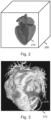
- Fig. 2 schematically shows an image volume 200 by way of its outline, with a segmentation model 210 having been applied to the image data of the image volume 200 resulting in the delineation or segmentation of a sub-volume 210 in the image volume 200.
- the sub-volume 210 is shown to correspond to the volume occupied by the segmentation model 210, and is therefore referenced by a same reference numeral and visualized by the same.
- model-based segmentation may be used to delineate a particular sub-volume, e.g., a 'sub-volume of interest'.
- the sub-volume may correspond to an anatomical region, such as an interior of the ribcage, an anatomical organ, such as the heart, or any other type of anatomical structure.
- the model-based segmentation may result in a set of points explicitly or implicitly defining a closed surface, e.g., a hull, which encompasses - and thereby delineates - a sub-volume of the image volume.
- An example of such model-based segmentation is described in " Automatic Model-based Segmentation of the Heart in CT Images" by Ecabert et al., IEEE Transactions on Medical Imaging 2008, 27(9), pp. 1189-1201 .
- a segmentation model may define more than an (outer) surface of an anatomical region or structure.
- a segmentation model may delineate an exterior of an organ as well as internal structures inside of the organ.
- the sub-volume may be delineated by the outer surface, e.g., a hull, of the segmentation model.
- the segmentation model may also directly and solely define such an outer surface.
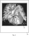
- Fig. 3 shows an example of a volume rendering 310 of the image data inside a sub-volume.
- the sub-volume here corresponds to an interior of the ribcage, and is thus different from the sub-volume of Fig. 2 which solely delineates the heart.
- image data outside the image volume is not shown, e.g., by having been excluded from input to the volume rendering technique or having been assigned a 100% opacity.
- the rendered sub-volume 310 comprises undesired (parts) of a structure. For example, in the case of Fig.
- the sub-volume includes a thin bone layer 315, thereby causing part of the heart to be obstructed in the volume rendering 310.
- This may be due to small, possibly sub-mm, deviations in the model-based segmentation.
- larger errors may occur during segmentation.
- a structure may have been wrongly excluded from the segmentation, such as an aorta that has been interpreted as the spine due to a limited field of view of the segmentation algorithm.
- the volume rendering may lack a structure which may be of interest to a user. In these and similar cases, it may be desired to adjust the sub-volume.
- segmentation may also be desirable in case the segmentation is correct.
- the segmentation model does not fully represent the anatomical region or structure of interest, and thus that a 'correction' of an - in principle correct - segmentation is desired.
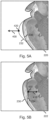
- Fig. 4 shows a viewport 330 which may be shown on a display as part of display content 300.
- the system 100 of Fig. 1 may generate such display content, with the display content being provided to the display in the form of display data.
- the display content 300 may comprise other content besides the viewport 330, including but not limited to buttons, menus, etc. of a graphical user interface.
- the display content may entirely consist of the viewport 330, in which case the viewport 330 is shown full-screen.
- the viewport 330 is shown to comprise a rendered sub-volume similar to the one shown in Fig. 3 .
- the user may use the viewport 330 to navigate within the image volume and obtain volume renderings from different perspectives of the sub-volume. Such navigation may be on the basis of the user providing navigation commands to the system 100 of Fig. 1 . These navigation commands may be translated by the system 100 into adjustments of the geometry of a viewing plane of the volume rendering, for example by adjusting a position or orientation of the viewing plane within the image volume.
- Such type of navigation is known per se.
- the adjustment tools provided by system 100 of Fig. 1 are schematically illustrated. Namely, it is illustrated that the user may, when presented with the viewport 330, select a push action which causes a part of the sub-volume to be pushed inwards, which is illustrated in Fig. 4 with arrow 410. Similarly, the user may select a pull action which causes a part of the sub-volume to be pulled outwards, which is illustrated in Fig. 4 with arrow 400.
- both push action and pull action cause a deformation orthogonally to the viewing plane, in that the pull action pulls the part of the sub-volume towards the user, and the push action pushes the part of the sub-volume away of the user.
- the direction of the push action and the pull action may be determined in various ways. For example, specific adjustment modes may be provided, in which the push action and the pull action operate in a certain plane. For example, as indicated in Fig. 4 , a frontal adjustment mode may be provided in which the pull action 400 and the push action 410 operate in a plane orthogonal to the viewing plane of the volume rendering 310, e.g., towards and away from the user.
- a frontal adjustment mode may be provided in which the pull action 400 and the push action 410 operate in a plane orthogonal to the viewing plane of the volume rendering 310, e.g., towards and away from the user.
- the direction of the adjustment may be dependent on the spatial orientation of the part of the sub-volume which is to be adjusted. For example, the direction of adjustment may always be perpendicular to its surface.
- the type of input command which is used to select and active the push/pull action may determine in which direction the push/pull action is carried out.
- the part of the sub-volume to which the push action 410 or the pull action 400 is applied may be selected to be centered around or otherwise positioned relative to a point 420 of the sub-volume.
- the point 420 may be selected by the system, e.g., as the point of the sub-volume which is shown in a center of viewport 330, or the point of the sub-volume which is closest to the viewing plane of the volume rendering.
- the user may indirectly influence the selection of the point, e.g., by rotating or moving the rendered sub-volume if the system provides such functionality.
- the user may manually select the point 420, e.g., via a cursor.
- the user interface provided by the system may further enable the user to select a spatial extent 430 and/or a strength of the push action 410 or the pull action 400.
- This spatial extent which is shown in Fig. 4 as a circle 430 defined by a spatial radius but which may also have any other shape, may define the size of the area on the surface of the sub-volume which is influenced by the push/pull operation. For example, an area may be selected based on the geodesic distance on the surface to the point 420, e.g., as a distance on the surface of a mesh representing the segmentation model, or an area that is given by the intersection of a sphere with the given spatial radius around the point with the sub-volume.
- the spatial radius, or in general the spatial extent may have a default value.
- a strength may be selected which defines how far the surface of the sub-volume is deformed by a push/pull action. The strength may be user-defined value or a default value.
- the push action and the pull action may be selected and activated in various ways.
- the selection and activation may be the same.
- the push/pull action may be selected and activated by a keyboard command or by mouse interaction, such as scrolling the wheel or dragging the mouse, whereby the inward ('push') or outward direction ('pull') may be determined based on the direction of the mouse interaction.
- the selection of the push/pull action may also take place in a graphical user interface, e.g., by selection from a menu, with the activation being, e.g., a mouse click.
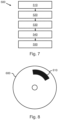
- Fig. 5A and 5B both illustrate, in cross-sectional views 220, 222 of the segmentation model, how the adjustment by a push/pull action locally deforms the segmentation model. It is noted that these Figures are provided for illustration purposes and do not represent the manner in which the adjustment is carried out by the user.
- Fig. 5A illustrates the pull action 400, where it can be seen that the surface 230 of the segmentation model (and thereby the sub-volume) is locally deformed outwards around point 420 by the pull action 400, resulting in a locally adjusted surface 232.
- Fig. 5B illustrates the push action 410, where it can be seen that the surface 230 is locally deformed inwards around point 420 by the push action 410, thereby resulting in a locally adjusted surface 234.
- Fig. 6 shows viewport 332 which may be shown on a display as part of display content 302, while further illustrating a side adjustment mode.
- the pull action 402 and the push action (not explicitly shown in Fig. 6 ) operate in a plane parallel to the viewing plane of the volume rendering 312.
- Fig. 6 further illustrates the point 422 around which the pull action 402 is performed, and the spatial extent 432 of the pull action.
- an outline 340 of a lateral side of the sub-volume may be visualized in the viewport.
- the outline 340 may be a line, or a lateral part of the surface of the sub-volume may be rendered in a semi-transparent manner. In some embodiments, the outline 340 may be 'dragged-and-dropped' to effect the push/pull action.
- image data surrounding the sub-volume in the image volume may also be volume rendered (reference numeral 320 in Fig. 6 ), but displayed in the viewport 322 in accordance with a different visualization parameter than the image data inside of the sub-volume.
- the volume rendering 320 of the image data surrounding the sub-volume may be displayed with a higher opacity or lower intensity.
- Fig. 6 shows the latter type of visualization.
- the sub-volume may be rerendered in the viewport.
- the sub-volume may be rerendered while a push/pull action is performed, e.g., already before its completion.
- the adjusted segmentation model may be saved after the interactive adjustment.
- the adjustment steps may be stored, and the user interface may provide redo and repeat operations.
- Fig. 7 shows a computer-implemented method 500 for volume rendering of image data of an image volume. It is noted that the method 500 may, but does not need to, correspond to an operation of the system 100 as described with reference to Fig. 1 and others.
- the method 500 comprises, in an operation titled "ACCESSING IMAGE DATA OF IMAGE VOLUME”, accessing 510 the image data of the image volume.
- the method 500 further comprises, in an operation titled “APPLYING SEGMENTATION MODEL TO IDENTIFY SUB-VOLUME”, applying 520 a segmentation model to the image data of the image volume, thereby delineating a sub-volume of the image volume.
- the method 500 further comprises, in an operation titled "VOLUME RENDERING OF IMAGE DATA OF SUB-VOLUME", generating 530 display data showing a viewport which comprises a volume rendering of image data inside the sub-volume.
- the method 500 further comprises, in an operation titled "ESTABLISHING USER INTERFACE", establishing 540 a user interface which enables the user to interactively adjust the sub-volume by applying at least one of: a push action and a pull action to the sub-volume, wherein the push action causes a part of the sub-volume to be pulled inwards, and wherein the pull action causes the part of the sub-volume to be pulled outwards.
- the method 500 further comprises, in an operation titled "UPDATING VOLUME RENDERING", updating 550 the volume rendering of the sub-volume in the viewport in response to an adjustment of the sub-volume by the user.
- the method 500 may be implemented on a computer as a computer implemented method, as dedicated hardware, or as a combination of both.
- instructions for the computer e.g., executable code
- the executable code may be stored in a transitory or non-transitory manner. Examples of computer readable mediums include memory devices, optical storage devices, integrated circuits, servers, online software, etc.
- Fig. 8 shows an optical disc 600.
- a system and method may be provided for volume rendering of image data of an image volume.
- a segmentation model may be applied to the image data of the image volume, thereby delineating a sub-volume of the image volume.
- the image data inside the sub-volume may be volume rendered.
- a user interface may be provided which enables a user to interactively adjust the sub-volume by applying at least one of: a push action and a pull action to the sub-volume.
- the push action may cause part of the sub-volume to be pulled inwards, whereas the pull action may cause part of the sub-volume to be pulled outwards.
- the volume rendering of the sub-volume may be updated in response to a user's adjustment of the sub-volume
- the invention also applies to computer programs, particularly computer programs on or in a carrier, adapted to put the invention into practice.
- the program may be in the form of a source code, an object code, a code intermediate source and an object code such as in a partially compiled form, or in any other form suitable for use in the implementation of the method according to the invention.
- a program may have many different architectural designs.
- a program code implementing the functionality of the method or system according to the invention may be sub-divided into one or more sub-routines. Many different ways of distributing the functionality among these sub-routines will be apparent to the skilled person.
- the sub-routines may be stored together in one executable file to form a self-contained program.
- Such an executable file may comprise computer-executable instructions, for example, processor instructions and/or interpreter instructions (e.g. Java interpreter instructions).
- one or more or all of the sub-routines may be stored in at least one external library file and linked with a main program either statically or dynamically, e.g. at run-time.
- the main program contains at least one call to at least one of the sub-routines.
- the sub-routines may also comprise function calls to each other.
- An embodiment relating to a computer program product comprises computer-executable instructions corresponding to each processing stage of at least one of the methods set forth herein. These instructions may be sub-divided into sub-routines and/or stored in one or more files that may be linked statically or dynamically.
- Another embodiment relating to a computer program product comprises computer-executable instructions corresponding to each means of at least one of the systems and/or products set forth herein. These instructions may be sub-divided into sub-routines and/or stored in one or more files that may be linked statically or dynamically.
- the carrier of a computer program may be any entity or device capable of carrying the program.
- the carrier may include a data storage, such as a ROM, for example, a CD ROM or a semiconductor ROM, or a magnetic recording medium, for example, a hard disk.
- the carrier may be a transmissible carrier such as an electric or optical signal, which may be conveyed via electric or optical cable or by radio or other means.
- the carrier may be constituted by such a cable or other device or means.
- the carrier may be an integrated circuit in which the program is embedded, the integrated circuit being adapted to perform, or used in the performance of, the relevant method.
Landscapes
- Engineering & Computer Science (AREA)
- Theoretical Computer Science (AREA)
- Physics & Mathematics (AREA)
- General Physics & Mathematics (AREA)
- General Engineering & Computer Science (AREA)
- Computer Graphics (AREA)
- Human Computer Interaction (AREA)
- Software Systems (AREA)
- Geometry (AREA)
- Architecture (AREA)
- Computer Hardware Design (AREA)
- Computing Systems (AREA)
- Computer Vision & Pattern Recognition (AREA)
- Apparatus For Radiation Diagnosis (AREA)
- Processing Or Creating Images (AREA)
- Image Generation (AREA)
- User Interface Of Digital Computer (AREA)
Claims (15)
- System (100) zum Volumenrendering von Bilddaten eines Bildvolumens (200), das einen Typ einer anatomischen Struktur zeigt, wobei das System umfasst:- eine Bilddatenschnittstelle (120), die konfiguriert ist, um auf die Bilddaten (030) des Bildvolumens zuzugreifen;- eine Benutzereingabeschnittstelle (184), die konfiguriert ist, um Benutzereingabedaten (082) von einer Benutzereingabevorrichtung (080), die von einem Benutzer bedient werden kann, zu empfangen;- eine Anzeigeausgabeschnittstelle (182), die konfiguriert ist, um Anzeigedaten (062) für eine Anzeige (060) bereitzustellen, um eine Ausgabe des Systems darzustellen;- einen Speicher (160), der Anweisungsdaten umfasst, die einen Satz Anweisungen repräsentieren;- einen Prozessor (140), der konfiguriert ist, um mit der Bilddatenschnittstelle, der Benutzereingabeschnittstelle, der Anzeigeausgabeschnittstelle und dem Speicher zu kommunizieren und den Satz Anweisungen auszuführen, wobei der Satz Anweisungen, wenn er vom Prozessor ausgeführt wird, bewirkt, dass der Prozessor:- auf Modelldaten zugreift, die ein Segmentierungsmodell zum Segmentieren des Typs einer anatomischen Struktur definieren;- das Segmentierungsmodell auf die Bilddaten des Bildvolumens (200) anwendet, wodurch ein Teilvolumen (210) des Bildvolumens, das eine Segmentierung der anatomischen Struktur im Bildvolumen repräsentiert, abgegrenzt wird;- die Anzeigedaten erzeugt, um ein Ansichtsfenster (330, 332) anzuzeigen, das ein Volumenrendering (310, 312) von Bilddaten innerhalb des Teilvolumens auf einer Ansichtsebene umfasst;- unter Verwendung der Benutzereingabeschnittstelle und der Anzeigeausgabeschnittstelle eine Benutzerschnittstelle erstellt, die es dem Benutzer ermöglicht:eine Geometrie der Ansichtsebene des Volumenrenderings interaktiv anzupassen, um eine vom Benutzer ausgewählte Ansichtsebene zu erstellen;das Teilvolumen interaktiv anzupassen durch Anwenden mindestens eines von: einer Schiebeaktion (410) und einer Ziehaktion (400, 402) auf das Teilvolumen, wobei die Schiebeaktion bewirkt, dass ein Teil des Teilvolumens nach innen gezogen wird, wobei die Ziehaktion bewirkt, dass der Teil des Teilvolumens nach außen gezogen wird, wobei der Teil des Teilvolumens, auf den die Schiebeaktion oder die Ziehaktion angewendet wird, vom Prozessor auf Basis der Geometrie der vom Benutzer ausgewählten Ansichtsebene ausgewählt wird,wobei das Volumenrendering des Teilvolumens im Ansichtsfenster in Reaktion auf eine Anpassung der Ansichtsebene oder des Teilvolumens durch den Benutzer aktualisiert wird.
- System (100) nach Anspruch 1, wobei die Schiebeaktion (410) oder die Ziehaktion (400, 402) vom Benutzer auf Basis mindestens eines ausgewählt und angewendet wird von: einem Tastaturbefehl und einer vordefinierten Mausinteraktion.
- System (100) nach Anspruch 1 oder 2, wobei der Teil des Teilvolumens (210), auf den die Schiebeaktion (410) oder die Ziehaktion (400, 402) angewendet wird, vom Prozessor auf Basis mindestens eines ausgewählt wird von:- einem Punkt (420, 422) des Teilvolumens, der in einer Mitte des Ansichtsfensters angezeigt wird,- einem Punkt des Teilvolumens, der der vom Benutzer ausgewählten Ansichtsebene des Volumenrenderings am nächsten liegt.
- System nach einem der Ansprüche 1 bis 3, wobei die Benutzerschnittstelle einen manuellen Auswahlmodus umfasst, in dem der Teil des Teilvolumens (210), auf den die Schiebeaktion (410) oder die Ziehaktion (400, 402) angewendet wird, vom Prozessor auf Basis einer Benutzerauswahl eines Punkts des Teilvolumens ausgewählt wird.
- System (100) nach einem der Ansprüche 1 bis 4, wobei die Benutzerschnittstelle es dem Benutzer ermöglicht, mindestens eines auszuwählen von: einer räumlichen Erstreckung (430, 432) und eine Stärke der Schiebeaktion (410) oder der Ziehaktion (400, 402).
- System (100) nach einem der Ansprüche 1 bis 5, wobei die Benutzerschnittstelle einen Seitenanpassungsmodus umfasst, in dem die Ziehaktion (402) und die Schiebeaktion in einer Ebene parallel zu der vom Benutzer ausgewählten Ansichtsebene des Volumenrenderings (312) erfolgen, und wobei, wenn der Seitenanpassungsmodus ausgewählt ist, ein Umriss (340) einer seitlichen Seite des Teilvolumens im Ansichtsfenster (332) dargestellt wird.
- System (100) nach Anspruch 6, wobei, wenn der Seitenanpassungsmodus ausgewählt ist, Bilddaten, die das Teilvolumen (210) im Bildvolumen (200) umgeben, ein Volumen sind, das mit einem anderen Darstellungsparameter als die Bilddaten innerhalb des Teilvolumens gerendert (320) und im Ansichtsfenster (322) angezeigt wird.
- System (100) nach Anspruch 7, wobei der andere Darstellungsparameter bewirkt, dass das Volumenrendering (320) der Bilddaten, die das Teilvolumen (210) umgeben, mit einer höheren Opazität oder niedrigeren Intensität angezeigt wird.
- System (100) nach einem der Ansprüche 1 bis 8, wobei die Benutzerschnittstelle einen Frontalanpassungsmodus umfasst, in dem die Ziehaktion (400) und die Schiebeaktion (410) in einer Ebene orthogonal zu der vom Benutzer ausgewählten Ansichtsebene des Volumenrenderings (310, 312) erfolgen.
- System (100) nach Anspruch 9, wobei, wenn der Frontalanpassungsmodus ausgewählt ist, Bilddaten, die das Teilvolumen (210) im Bildvolumen (200) umgeben, vom Volumenrendering (310, 312) ausgeschlossen werden oder beim Volumenrendering eine Opazität von 100 % zugewiesen bekommen.
- System (100) nach einem der Ansprüche 1 bis 10, wobei das Segmentierungsmodell ein Maschenmodell ist.
- System (100) nach einem der Ansprüche 1 bis 11, wobei das Segmentierungsmodell eine geschlossene Hülle definiert.
- Arbeitsstation oder Bildgebungseinrichtung, die das System (100) nach einem der Ansprüche 1 bis 12 umfasst.
- Computerimplementiertes Verfahren (500) zum Volumenrendering von Bilddaten eines Bildvolumens, das einen Typ einer anatomischen Struktur zeigt, wobei das Verfahren umfasst:- Zugreifen (510) auf die Bilddaten des Bildvolumens;- Zugreifen auf Modelldaten, die ein Segmentierungsmodell zum Segmentieren des Typs einer anatomischen Struktur definieren;- Anwenden (520) des Segmentierungsmodells auf die Bilddaten des Bildvolumens, wodurch ein Teilvolumen des Bildvolumens, das eine Segmentierung der anatomischen Struktur im Bildvolumen repräsentiert, abgegrenzt wird;- Erzeugen (530) von Anzeigedaten, die ein Ansichtsfenster zeigen, das ein Volumenrendering von Bilddaten innerhalb des Teilvolumens auf einer Anzeigeebene umfasst;- Erstellen (540) einer Benutzerschnittstelle, die es dem Benutzer ermöglicht:eine Geometrie der Ansichtsebene des Volumenrenderings interaktiv anzupassen, um eine vom Benutzer ausgewählte Ansichtsebene zu erstellen;das Teilvolumen interaktiv anzupassen durch Anwenden mindestens eines von: einer Schiebeaktion und einer Ziehaktion auf das Teilvolumen, wobei die Schiebeaktion bewirkt, dass ein Teil des Teilvolumens nach innen gezogen wird, und wobei die Ziehaktion bewirkt, dass der Teil des Teilvolumens nach außen gezogen wird, wobei der Teil des Teilvolumens, auf den die Schiebeaktion oder die Ziehaktion angewendet wird, vom Prozessor auf Basis der Geometrie der vom Benutzer ausgewählten Ansichtsebene ausgewählt wird; und- Aktualisieren (550) des Volumenrenderings des Teilvolumens im Ansichtsfenster in Reaktion auf eine Anpassung der Ansichtsebene oder des Teilvolumens durch den Benutzer.
- Computerlesbares Medium (600), das flüchtige oder nichtflüchtige Daten (610) umfasst, die Anweisungen repräsentieren, die dazu eingerichtet sind, zu bewirken, dass ein Prozessorsystem das computerimplementierte Verfahren nach Anspruch 14 durchführt.
Applications Claiming Priority (2)
| Application Number | Priority Date | Filing Date | Title |
|---|---|---|---|
| EP17185118.1A EP3441944A1 (de) | 2017-08-07 | 2017-08-07 | Volumetrische darstellung von volumetrischen bilddaten mit interactiver segmentierung |
| PCT/EP2018/070369 WO2019030012A1 (en) | 2017-08-07 | 2018-07-27 | RENDERING VOLUMETRIC IMAGE DATA VOLUME WITH INTERACTIVE SEGMENTATION |
Publications (2)
| Publication Number | Publication Date |
|---|---|
| EP3665655A1 EP3665655A1 (de) | 2020-06-17 |
| EP3665655B1 true EP3665655B1 (de) | 2025-02-19 |
Family
ID=59676994
Family Applications (2)
| Application Number | Title | Priority Date | Filing Date |
|---|---|---|---|
| EP17185118.1A Withdrawn EP3441944A1 (de) | 2017-08-07 | 2017-08-07 | Volumetrische darstellung von volumetrischen bilddaten mit interactiver segmentierung |
| EP18743822.1A Active EP3665655B1 (de) | 2017-08-07 | 2018-07-27 | Volumetrische darstellung von volumetrischen bilddaten mit interaktiver segmentierung |
Family Applications Before (1)
| Application Number | Title | Priority Date | Filing Date |
|---|---|---|---|
| EP17185118.1A Withdrawn EP3441944A1 (de) | 2017-08-07 | 2017-08-07 | Volumetrische darstellung von volumetrischen bilddaten mit interactiver segmentierung |
Country Status (5)
| Country | Link |
|---|---|
| US (1) | US20200250880A1 (de) |
| EP (2) | EP3441944A1 (de) |
| JP (1) | JP7373484B2 (de) |
| CN (1) | CN110998667A (de) |
| WO (1) | WO2019030012A1 (de) |
Families Citing this family (5)
| Publication number | Priority date | Publication date | Assignee | Title |
|---|---|---|---|---|
| EP3839895A1 (de) * | 2019-12-19 | 2021-06-23 | Koninklijke Philips N.V. | Maschenkorrektur in abhängigkeit von der maschennormalrichtung |
| CN115223035A (zh) * | 2021-04-20 | 2022-10-21 | 阿里巴巴新加坡控股有限公司 | 图像检测方法、装置、设备和存储介质 |
| US12567150B2 (en) * | 2021-08-17 | 2026-03-03 | Siemens Healthineers Ag | Editing presegmented images and volumes using deep learning |
| US12198349B2 (en) | 2022-01-25 | 2025-01-14 | GE Precision Healthcare LLC | Methods and systems for real-time image 3D segmentation regularization |
| US20240020926A1 (en) * | 2022-07-14 | 2024-01-18 | Biosense Webster (Israel) Ltd. | Correcting a segmentation curve in an anatomical model |
Family Cites Families (8)
| Publication number | Priority date | Publication date | Assignee | Title |
|---|---|---|---|---|
| US8698795B2 (en) * | 2008-01-24 | 2014-04-15 | Koninklijke Philips N.V. | Interactive image segmentation |
| EP2444939A1 (de) * | 2009-10-15 | 2012-04-25 | Hitachi Aloka Medical, Ltd. | Vorrichtung zur Verarbeitung von Ultraschallvolumendaten |
| JP5437767B2 (ja) | 2009-10-15 | 2014-03-12 | 日立アロカメディカル株式会社 | 超音波ボリュームデータ処理装置 |
| US8819591B2 (en) * | 2009-10-30 | 2014-08-26 | Accuray Incorporated | Treatment planning in a virtual environment |
| US8970581B2 (en) * | 2012-01-04 | 2015-03-03 | Carestream Health, Inc. | System and method for interactive contouring for 3D medical images |
| EP3224803A1 (de) * | 2014-11-28 | 2017-10-04 | Koninklijke Philips N.V. | Modellbasierte segmentierung einer anatomischen struktur |
| US10282917B2 (en) | 2015-06-29 | 2019-05-07 | Koninklijke Philips N.V. | Interactive mesh editing |
| JP6565514B2 (ja) | 2015-09-09 | 2019-08-28 | 株式会社島津製作所 | 放射線撮影装置 |
-
2017
- 2017-08-07 EP EP17185118.1A patent/EP3441944A1/de not_active Withdrawn
-
2018
- 2018-07-27 WO PCT/EP2018/070369 patent/WO2019030012A1/en not_active Ceased
- 2018-07-27 JP JP2020505396A patent/JP7373484B2/ja active Active
- 2018-07-27 EP EP18743822.1A patent/EP3665655B1/de active Active
- 2018-07-27 CN CN201880051036.9A patent/CN110998667A/zh active Pending
- 2018-07-27 US US16/637,102 patent/US20200250880A1/en not_active Abandoned
Also Published As
| Publication number | Publication date |
|---|---|
| WO2019030012A1 (en) | 2019-02-14 |
| JP7373484B2 (ja) | 2023-11-02 |
| CN110998667A (zh) | 2020-04-10 |
| US20200250880A1 (en) | 2020-08-06 |
| EP3665655A1 (de) | 2020-06-17 |
| JP2020530156A (ja) | 2020-10-15 |
| EP3441944A1 (de) | 2019-02-13 |
Similar Documents
| Publication | Publication Date | Title |
|---|---|---|
| EP2486548B1 (de) | Interaktive auswahl eines gewünschten volumens in einem bild | |
| EP3665655B1 (de) | Volumetrische darstellung von volumetrischen bilddaten mit interaktiver segmentierung | |
| CN107851337B (zh) | 交互式网格编辑 | |
| US9349220B2 (en) | Curve correction in volume data sets | |
| EP2724317B1 (de) | System und verfahren zur verarbeitung eines medizinischen bildes | |
| CN102859552B (zh) | 图像数据分割 | |
| EP3731179A1 (de) | Systeme und verfahren zur halbautomatischen segmentierung eines medizinischen 3d-bildes unter verwendung einer in echtzeit edge-bewussten bürste | |
| EP3198565B1 (de) | Visualisieren eines volumetrischen bildes einer anatomischen struktur | |
| CN108701492B (zh) | 医学图像导航系统 | |
| US20140152649A1 (en) | Inspector Tool for Viewing 3D Images | |
| CN103258323B (zh) | 用于测量在医学成像数据中的变量比率的方法和装置 | |
| EP1828978A1 (de) | Verfahren, vorrichtung und computerprogramm zur segmentierung einer struktur in einem mehrdimensionalen datensatz | |
| BR112017005715B1 (pt) | Sistema e método para visualização de uma imagem volumétrica de uma estrutura anatômica, e equipamento de imageamento |
Legal Events
| Date | Code | Title | Description |
|---|---|---|---|
| STAA | Information on the status of an ep patent application or granted ep patent |
Free format text: STATUS: UNKNOWN |
|
| STAA | Information on the status of an ep patent application or granted ep patent |
Free format text: STATUS: THE INTERNATIONAL PUBLICATION HAS BEEN MADE |
|
| PUAI | Public reference made under article 153(3) epc to a published international application that has entered the european phase |
Free format text: ORIGINAL CODE: 0009012 |
|
| STAA | Information on the status of an ep patent application or granted ep patent |
Free format text: STATUS: REQUEST FOR EXAMINATION WAS MADE |
|
| 17P | Request for examination filed |
Effective date: 20200309 |
|
| AK | Designated contracting states |
Kind code of ref document: A1 Designated state(s): AL AT BE BG CH CY CZ DE DK EE ES FI FR GB GR HR HU IE IS IT LI LT LU LV MC MK MT NL NO PL PT RO RS SE SI SK SM TR |
|
| AX | Request for extension of the european patent |
Extension state: BA ME |
|
| DAV | Request for validation of the european patent (deleted) | ||
| DAX | Request for extension of the european patent (deleted) | ||
| STAA | Information on the status of an ep patent application or granted ep patent |
Free format text: STATUS: EXAMINATION IS IN PROGRESS |
|
| 17Q | First examination report despatched |
Effective date: 20211214 |
|
| GRAP | Despatch of communication of intention to grant a patent |
Free format text: ORIGINAL CODE: EPIDOSNIGR1 |
|
| STAA | Information on the status of an ep patent application or granted ep patent |
Free format text: STATUS: GRANT OF PATENT IS INTENDED |
|
| RIC1 | Information provided on ipc code assigned before grant |
Ipc: G06T 7/11 20170101ALI20240904BHEP Ipc: G06T 19/20 20110101ALI20240904BHEP Ipc: G06T 15/08 20110101AFI20240904BHEP |
|
| INTG | Intention to grant announced |
Effective date: 20240917 |
|
| GRAS | Grant fee paid |
Free format text: ORIGINAL CODE: EPIDOSNIGR3 |
|
| GRAA | (expected) grant |
Free format text: ORIGINAL CODE: 0009210 |
|
| STAA | Information on the status of an ep patent application or granted ep patent |
Free format text: STATUS: THE PATENT HAS BEEN GRANTED |
|
| AK | Designated contracting states |
Kind code of ref document: B1 Designated state(s): AL AT BE BG CH CY CZ DE DK EE ES FI FR GB GR HR HU IE IS IT LI LT LU LV MC MK MT NL NO PL PT RO RS SE SI SK SM TR |
|
| REG | Reference to a national code |
Ref country code: GB Ref legal event code: FG4D |
|
| REG | Reference to a national code |
Ref country code: CH Ref legal event code: EP |
|
| REG | Reference to a national code |
Ref country code: IE Ref legal event code: FG4D |
|
| REG | Reference to a national code |
Ref country code: DE Ref legal event code: R096 Ref document number: 602018079310 Country of ref document: DE |
|
| REG | Reference to a national code |
Ref country code: DE Ref legal event code: R084 Ref document number: 602018079310 Country of ref document: DE |
|
| REG | Reference to a national code |
Ref country code: GB Ref legal event code: 746 Effective date: 20250331 |
|
| REG | Reference to a national code |
Ref country code: NL Ref legal event code: MP Effective date: 20250219 |
|
| PG25 | Lapsed in a contracting state [announced via postgrant information from national office to epo] |
Ref country code: RS Free format text: LAPSE BECAUSE OF FAILURE TO SUBMIT A TRANSLATION OF THE DESCRIPTION OR TO PAY THE FEE WITHIN THE PRESCRIBED TIME-LIMIT Effective date: 20250519 |
|
| PG25 | Lapsed in a contracting state [announced via postgrant information from national office to epo] |
Ref country code: FI Free format text: LAPSE BECAUSE OF FAILURE TO SUBMIT A TRANSLATION OF THE DESCRIPTION OR TO PAY THE FEE WITHIN THE PRESCRIBED TIME-LIMIT Effective date: 20250219 |
|
| PG25 | Lapsed in a contracting state [announced via postgrant information from national office to epo] |
Ref country code: PL Free format text: LAPSE BECAUSE OF FAILURE TO SUBMIT A TRANSLATION OF THE DESCRIPTION OR TO PAY THE FEE WITHIN THE PRESCRIBED TIME-LIMIT Effective date: 20250219 |
|
| PG25 | Lapsed in a contracting state [announced via postgrant information from national office to epo] |
Ref country code: ES Free format text: LAPSE BECAUSE OF FAILURE TO SUBMIT A TRANSLATION OF THE DESCRIPTION OR TO PAY THE FEE WITHIN THE PRESCRIBED TIME-LIMIT Effective date: 20250219 |
|
| REG | Reference to a national code |
Ref country code: LT Ref legal event code: MG9D |
|
| PG25 | Lapsed in a contracting state [announced via postgrant information from national office to epo] |
Ref country code: NO Free format text: LAPSE BECAUSE OF FAILURE TO SUBMIT A TRANSLATION OF THE DESCRIPTION OR TO PAY THE FEE WITHIN THE PRESCRIBED TIME-LIMIT Effective date: 20250519 Ref country code: IS Free format text: LAPSE BECAUSE OF FAILURE TO SUBMIT A TRANSLATION OF THE DESCRIPTION OR TO PAY THE FEE WITHIN THE PRESCRIBED TIME-LIMIT Effective date: 20250619 |
|
| PG25 | Lapsed in a contracting state [announced via postgrant information from national office to epo] |
Ref country code: NL Free format text: LAPSE BECAUSE OF FAILURE TO SUBMIT A TRANSLATION OF THE DESCRIPTION OR TO PAY THE FEE WITHIN THE PRESCRIBED TIME-LIMIT Effective date: 20250219 |
|
| PG25 | Lapsed in a contracting state [announced via postgrant information from national office to epo] |
Ref country code: HR Free format text: LAPSE BECAUSE OF FAILURE TO SUBMIT A TRANSLATION OF THE DESCRIPTION OR TO PAY THE FEE WITHIN THE PRESCRIBED TIME-LIMIT Effective date: 20250219 |
|
| PG25 | Lapsed in a contracting state [announced via postgrant information from national office to epo] |
Ref country code: LV Free format text: LAPSE BECAUSE OF FAILURE TO SUBMIT A TRANSLATION OF THE DESCRIPTION OR TO PAY THE FEE WITHIN THE PRESCRIBED TIME-LIMIT Effective date: 20250219 Ref country code: PT Free format text: LAPSE BECAUSE OF FAILURE TO SUBMIT A TRANSLATION OF THE DESCRIPTION OR TO PAY THE FEE WITHIN THE PRESCRIBED TIME-LIMIT Effective date: 20250620 |
|
| PG25 | Lapsed in a contracting state [announced via postgrant information from national office to epo] |
Ref country code: BG Free format text: LAPSE BECAUSE OF FAILURE TO SUBMIT A TRANSLATION OF THE DESCRIPTION OR TO PAY THE FEE WITHIN THE PRESCRIBED TIME-LIMIT Effective date: 20250219 Ref country code: GR Free format text: LAPSE BECAUSE OF FAILURE TO SUBMIT A TRANSLATION OF THE DESCRIPTION OR TO PAY THE FEE WITHIN THE PRESCRIBED TIME-LIMIT Effective date: 20250520 |
|
| REG | Reference to a national code |
Ref country code: AT Ref legal event code: MK05 Ref document number: 1769062 Country of ref document: AT Kind code of ref document: T Effective date: 20250219 |
|
| PG25 | Lapsed in a contracting state [announced via postgrant information from national office to epo] |
Ref country code: SE Free format text: LAPSE BECAUSE OF FAILURE TO SUBMIT A TRANSLATION OF THE DESCRIPTION OR TO PAY THE FEE WITHIN THE PRESCRIBED TIME-LIMIT Effective date: 20250219 |
|
| PG25 | Lapsed in a contracting state [announced via postgrant information from national office to epo] |
Ref country code: SM Free format text: LAPSE BECAUSE OF FAILURE TO SUBMIT A TRANSLATION OF THE DESCRIPTION OR TO PAY THE FEE WITHIN THE PRESCRIBED TIME-LIMIT Effective date: 20250219 |
|
| PG25 | Lapsed in a contracting state [announced via postgrant information from national office to epo] |
Ref country code: DK Free format text: LAPSE BECAUSE OF FAILURE TO SUBMIT A TRANSLATION OF THE DESCRIPTION OR TO PAY THE FEE WITHIN THE PRESCRIBED TIME-LIMIT Effective date: 20250219 |
|
| PGFP | Annual fee paid to national office [announced via postgrant information from national office to epo] |
Ref country code: DE Payment date: 20250728 Year of fee payment: 8 |
|
| PG25 | Lapsed in a contracting state [announced via postgrant information from national office to epo] |
Ref country code: IT Free format text: LAPSE BECAUSE OF FAILURE TO SUBMIT A TRANSLATION OF THE DESCRIPTION OR TO PAY THE FEE WITHIN THE PRESCRIBED TIME-LIMIT Effective date: 20250219 |
|
| PGFP | Annual fee paid to national office [announced via postgrant information from national office to epo] |
Ref country code: GB Payment date: 20250722 Year of fee payment: 8 |
|
| PG25 | Lapsed in a contracting state [announced via postgrant information from national office to epo] |
Ref country code: AT Free format text: LAPSE BECAUSE OF FAILURE TO SUBMIT A TRANSLATION OF THE DESCRIPTION OR TO PAY THE FEE WITHIN THE PRESCRIBED TIME-LIMIT Effective date: 20250219 |
|
| PGFP | Annual fee paid to national office [announced via postgrant information from national office to epo] |
Ref country code: FR Payment date: 20250725 Year of fee payment: 8 |
|
| PG25 | Lapsed in a contracting state [announced via postgrant information from national office to epo] |
Ref country code: CZ Free format text: LAPSE BECAUSE OF FAILURE TO SUBMIT A TRANSLATION OF THE DESCRIPTION OR TO PAY THE FEE WITHIN THE PRESCRIBED TIME-LIMIT Effective date: 20250219 Ref country code: EE Free format text: LAPSE BECAUSE OF FAILURE TO SUBMIT A TRANSLATION OF THE DESCRIPTION OR TO PAY THE FEE WITHIN THE PRESCRIBED TIME-LIMIT Effective date: 20250219 |
|
| PG25 | Lapsed in a contracting state [announced via postgrant information from national office to epo] |
Ref country code: RO Free format text: LAPSE BECAUSE OF FAILURE TO SUBMIT A TRANSLATION OF THE DESCRIPTION OR TO PAY THE FEE WITHIN THE PRESCRIBED TIME-LIMIT Effective date: 20250219 |
|
| PG25 | Lapsed in a contracting state [announced via postgrant information from national office to epo] |
Ref country code: SK Free format text: LAPSE BECAUSE OF FAILURE TO SUBMIT A TRANSLATION OF THE DESCRIPTION OR TO PAY THE FEE WITHIN THE PRESCRIBED TIME-LIMIT Effective date: 20250219 |
|
| REG | Reference to a national code |
Ref country code: DE Ref legal event code: R097 Ref document number: 602018079310 Country of ref document: DE |
|
| PLBE | No opposition filed within time limit |
Free format text: ORIGINAL CODE: 0009261 |
|
| STAA | Information on the status of an ep patent application or granted ep patent |
Free format text: STATUS: NO OPPOSITION FILED WITHIN TIME LIMIT |
|
| REG | Reference to a national code |
Ref country code: CH Ref legal event code: L10 Free format text: ST27 STATUS EVENT CODE: U-0-0-L10-L00 (AS PROVIDED BY THE NATIONAL OFFICE) Effective date: 20251231 |
|
| 26N | No opposition filed |
Effective date: 20251120 |
|
| REG | Reference to a national code |
Ref country code: CH Ref legal event code: H13 Free format text: ST27 STATUS EVENT CODE: U-0-0-H10-H13 (AS PROVIDED BY THE NATIONAL OFFICE) Effective date: 20260224 |
|
| PG25 | Lapsed in a contracting state [announced via postgrant information from national office to epo] |
Ref country code: LU Free format text: LAPSE BECAUSE OF NON-PAYMENT OF DUE FEES Effective date: 20250727 |
|
| REG | Reference to a national code |
Ref country code: BE Ref legal event code: MM Effective date: 20250731 |
|
| PG25 | Lapsed in a contracting state [announced via postgrant information from national office to epo] |
Ref country code: BE Free format text: LAPSE BECAUSE OF NON-PAYMENT OF DUE FEES Effective date: 20250731 |
|
| PG25 | Lapsed in a contracting state [announced via postgrant information from national office to epo] |
Ref country code: CH Free format text: LAPSE BECAUSE OF NON-PAYMENT OF DUE FEES Effective date: 20250731 |