EP3665663B1 - Capteur de sécurité proche-éloigné - Google Patents
Capteur de sécurité proche-éloigné Download PDFInfo
- Publication number
- EP3665663B1 EP3665663B1 EP18843401.3A EP18843401A EP3665663B1 EP 3665663 B1 EP3665663 B1 EP 3665663B1 EP 18843401 A EP18843401 A EP 18843401A EP 3665663 B1 EP3665663 B1 EP 3665663B1
- Authority
- EP
- European Patent Office
- Prior art keywords
- sensor
- sub
- magnetic field
- processor
- far
- Prior art date
- Legal status (The legal status is an assumption and is not a legal conclusion. Google has not performed a legal analysis and makes no representation as to the accuracy of the status listed.)
- Active
Links
Images



Classifications
-
- G—PHYSICS
- G08—SIGNALLING
- G08B—SIGNALLING SYSTEMS, e.g. PERSONAL CALLING SYSTEMS; ORDER TELEGRAPHS; ALARM SYSTEMS
- G08B13/00—Burglar, theft or intruder alarms
- G08B13/22—Electrical actuation
- G08B13/24—Electrical actuation by interference with electromagnetic field distribution
- G08B13/2491—Intrusion detection systems, i.e. where the body of an intruder causes the interference with the electromagnetic field
-
- G—PHYSICS
- G01—MEASURING; TESTING
- G01B—MEASURING LENGTH, THICKNESS OR SIMILAR LINEAR DIMENSIONS; MEASURING ANGLES; MEASURING AREAS; MEASURING IRREGULARITIES OF SURFACES OR CONTOURS
- G01B7/00—Measuring arrangements characterised by the use of electric or magnetic techniques
- G01B7/14—Measuring arrangements characterised by the use of electric or magnetic techniques for measuring distance or clearance between spaced objects or spaced apertures
-
- G—PHYSICS
- G01—MEASURING; TESTING
- G01R—MEASURING ELECTRIC VARIABLES; MEASURING MAGNETIC VARIABLES
- G01R33/00—Arrangements or instruments for measuring magnetic variables
- G01R33/0023—Electronic aspects, e.g. circuits for stimulation, evaluation, control; Treating the measured signals; calibration
-
- G—PHYSICS
- G01—MEASURING; TESTING
- G01R—MEASURING ELECTRIC VARIABLES; MEASURING MAGNETIC VARIABLES
- G01R33/00—Arrangements or instruments for measuring magnetic variables
- G01R33/02—Measuring direction or magnitude of magnetic fields or magnetic flux
-
- G—PHYSICS
- G01—MEASURING; TESTING
- G01R—MEASURING ELECTRIC VARIABLES; MEASURING MAGNETIC VARIABLES
- G01R33/00—Arrangements or instruments for measuring magnetic variables
- G01R33/02—Measuring direction or magnitude of magnetic fields or magnetic flux
- G01R33/06—Measuring direction or magnitude of magnetic fields or magnetic flux using galvano-magnetic devices
- G01R33/07—Hall effect devices
- G01R33/072—Constructional adaptation of the sensor to specific applications
-
- G—PHYSICS
- G08—SIGNALLING
- G08B—SIGNALLING SYSTEMS, e.g. PERSONAL CALLING SYSTEMS; ORDER TELEGRAPHS; ALARM SYSTEMS
- G08B13/00—Burglar, theft or intruder alarms
- G08B13/02—Mechanical actuation
- G08B13/08—Mechanical actuation by opening, e.g. of door, of window, of drawer, of shutter, of curtain, of blind
-
- G—PHYSICS
- G08—SIGNALLING
- G08B—SIGNALLING SYSTEMS, e.g. PERSONAL CALLING SYSTEMS; ORDER TELEGRAPHS; ALARM SYSTEMS
- G08B21/00—Alarms responsive to a single specified undesired or abnormal condition and not otherwise provided for
- G08B21/18—Status alarms
- G08B21/22—Status alarms responsive to presence or absence of persons
-
- G—PHYSICS
- G08—SIGNALLING
- G08B—SIGNALLING SYSTEMS, e.g. PERSONAL CALLING SYSTEMS; ORDER TELEGRAPHS; ALARM SYSTEMS
- G08B29/00—Checking or monitoring of signalling or alarm systems; Prevention or correction of operating errors, e.g. preventing unauthorised operation
- G08B29/02—Monitoring continuously signalling or alarm systems
- G08B29/04—Monitoring of the detection circuits
- G08B29/046—Monitoring of the detection circuits prevention of tampering with detection circuits
-
- G—PHYSICS
- G08—SIGNALLING
- G08B—SIGNALLING SYSTEMS, e.g. PERSONAL CALLING SYSTEMS; ORDER TELEGRAPHS; ALARM SYSTEMS
- G08B29/00—Checking or monitoring of signalling or alarm systems; Prevention or correction of operating errors, e.g. preventing unauthorised operation
- G08B29/18—Prevention or correction of operating errors
- G08B29/20—Calibration, including self-calibrating arrangements
Definitions
- the present application relates to the field of home security. More specifically, the present application relates to a security sensor for monitoring a barrier.
- a local alarm condition i.e., unauthorized opening of a door or window
- a signal may be generated by circuitry located within the reed switch assembly and sent, via wires or over-the-air, to the alarm panel.
- a loud audible alert is generated, either at the alarm panel in the home or directly by the circuitry within the reed switch assembly, indicating that a door or window has been opened without authorization.
- US 2016/0187118 describes systems and techniques for guided installation of an opening sensor. A strength of a magnetic field created by a magnet of an opening sensor at a location of a magnetometer sensor of the opening sensor may be determined. Feedback may be provided to an installer of the opening sensor based on the determined strength of the magnetic field.
- the present description relates to a "near-far" door or window security sensor that can be used in installations where either a wide or a narrow door or window frame may be present.
- FIG. 1 is an illustration of a prior art security system.
- a door 100 and a window 102 are monitored by barrier alarms (i.e., door/window sensors) 104 and 106, respectively.
- Each of the barrier alarms comprises a magnet 108 and a sensor 110.
- Magnet 108 is shown in FIG. 1 as mounted on a movable portion of door 100 and window 102, while sensor 110 is mounted on a wall on the other side of door jamb 114 and casing 116, in proximity to magnet 108 when door 100 or window 102 is in a closed position.
- magnet 108 may be mounted to the wall and sensor 110 mounted to the movable door or window portion.
- Sensor 110 detects a magnetic field produced by the magnet and uses this detection as a basis for determining whether the door 100 or window 102 is open, closed, partially open, or transitioning between any of these states.
- Each of the barrier alarms communicate with alarm panel 112, typically using wireless RF signals generated by the barrier alarms and/or alarm panel 112. For example, if door 100 is opened, sensor 108 detects a reduction or elimination of a magnetic field produced by magnet 108 as magnet 108 moves away from sensor 108 as door 100 is opened. In response, barrier alarm 104/106 generates and transmits an alarm signal to alarm panel 112 indicative of a local alarm condition, e.g., door 100 has been opened.
- alarm panel 112 may send messages to either of the barrier alarms requesting a status of either one, e.g., whether a barrier being monitored is "open”, “closed”, partially open, a battery status, a tamper status, etc.
- one or both barrier alarms may transmit a response to alarm panel 112 indicating such a status, as the case may be.
- Other commands may be transmitted by alarm panel 112, such as "sound alarm”, “turn on warning light”, open gate, lock door, unlock window, etc.
- alarm panel 112 performs monitoring of barrier alarms 104, 106, and other security devices (for example, tilt sensors, shock sensors, motion detectors, passive infra-red detectors, light interruption detectors, etc.) that may be part of the security system.
- alarm panel 112 may provide an audible and/or visual status of the various sensors in the system (e.g., "open”, “closed”, “partially open”, “open more than X distance”, "on", “off', "normal”, “alarm”, “locked”, “unlocked”, etc.).
- Alarm panel 112 may also be in communication with an off-site remote monitoring station 124 via communication network 122, such as the Internet, PSTN, a fiber optic communication network, a wireless communication network (e.g., cellular, data, satellite, etc.), and/or other wide-area network.
- Remote monitoring station 124 typically provides security monitoring services for homes and businesses equipped with security systems such as the one shown in FIG. 1 .
- Remote monitoring station 124 is adapted to receive communications from alarm panel 112 via network 122 in response to alarm panel 112 receiving an indication of a local alarm condition being sensed by one or more barrier alarms/sensors in the security system.
- alarm panel 112 simply receives raw data from the barrier alarms and determines, based on the data, whether a local alarm condition has occurred.
- alarm panel 112 When a local alarm condition is detected, alarm panel 112 generates a system alarm which may comprise taking one or more actions, such as notifying remote monitoring station 124 that a local alarm condition has occurred, illuminating one or more lights, sounding one or more audible alerts, etc.
- Such a user input device 210 may comprise a mechanical switch (i.e., pushbutton, momentary pushbutton, toggle, slide, etc.), an opto-electrical switch, a heat sensing device (to detect the presence of a human finger), a capacitive sensor, a microphone, or any other type of switch or sensor to provide an indication to near-far sensor 200 that a user wishes to place near-far sensor 200 into a configuration mode or a calibration mode, and/or to provide signals to the processor within near-far sensor 200 indicating that the window (or door) is in a certain position during a calibration process, for example, closed, open, partially open, opened a predetermined distance (for example, 6 inches, allowing air to enter the window or door, but not enough for a person to pass).
- a mechanical switch i.e., pushbutton, momentary pushbutton, toggle, slide, etc.
- an opto-electrical switch to detect the presence of a human finger
- a capacitive sensor to detect the presence of a
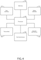
- First sub-sensor 404 is coupled to processor 400 and senses one or more attributes of a magnetic field produced by magnet 202.
- first sub-sensor 404 may detect the strength, direction, and/or polarity of the magnetic field produced by magnet 202, in one or more axis, and produce a signal in accordance with one or more of these properties.
- An example of such a first sub-sensor 404 is a typical reed switch, used in the security industry for many years. Typically, in order to change the state of a typical reed switch used in prior art security sensors, a certain threshold magnetic field is needed, which is a relatively strong magnetic field strength. The measure of the magnetic field strength required to operate a reed switch is generally expressed in ampere turns.
- processor 400 will determine that the window is in the closed position by comparing readings of the Hall Effect sensor to 90% of 812, or 731 as the threshold variance, to determine that the window is closed. Any reading less than the threshold variance would indicate that magnet 102 has been moved far enough from near-far sensor 200 as to indicate that the door or window has been opened.
Landscapes
- Physics & Mathematics (AREA)
- General Physics & Mathematics (AREA)
- Condensed Matter Physics & Semiconductors (AREA)
- Electromagnetism (AREA)
- Business, Economics & Management (AREA)
- Emergency Management (AREA)
- Burglar Alarm Systems (AREA)
- Emergency Alarm Devices (AREA)
Claims (4)
- Capteur de sécurité proche-éloigné (200) pour surveiller une barrière, comprenant :un premier sous-capteur (404) pour détecter un champ magnétique produit par un aimant (202) ;un deuxième sous-capteur (406) pour détecter le champ magnétique, dans lequel le premier sous-capteur présente une première sensibilité au champ magnétique et le deuxième sous-capteur présente une deuxième sensibilité au champ magnétique, dans lequel la deuxième sensibilité au champ magnétique est au moins cinq fois plus élevée que la première sensibilité au champ magnétique ;une mémoire (402) pour stocker des instructions exécutables par un processeur ; etun processeur (400) couplé au premier sous-capteur, au deuxième sous-capteur et à la mémoire pour exécuter des instructions exécutables par un processeur qui amènent le capteur proche-éloigné à :sélectionner l'un des sous-capteurs à surveiller pendant un mode de fonctionnement normal ;surveiller le sous-capteur sélectionné pendant le mode de fonctionnement normal ;déterminer si la barrière a été ouverte sur base du premier sous-capteur ou du deuxième sous-capteur, en fonction de quel sous-capteur a été sélectionné ;dans lequelles instructions exécutables par un processeur comprennent en outre des instructions qui amènent le capteur proche-éloigné à surveiller périodiquement le sous-capteur qui n'a pas été sélectionné,déterminer une lecture du sous-capteur sélectionné à des premiers intervalles de temps prédéterminés ;déterminer une deuxième lecture du sous-capteur non sélectionné à des deuxièmes intervalles de temps prédéterminés, dans lequel les deuxièmes intervalles de temps prédéterminés sont plus grands que les premiers intervalles de temps prédéterminés, etdéterminer qu'une condition anormale est présente lorsque le sous-capteur sélectionné n'indique pas que la barrière a été ouverte et que le sous-capteur non sélectionné détermine la présence d'un deuxième champ magnétique produit par un deuxième aimant.
- Capteur de sécurité proche-éloigné selon la revendication 1,
dans lequel le premier sous-capteur comprend un commutateur à lames souples et le deuxième sous-capteur comprend un capteur à effet Hall ou une magnétorésistance. - Capteur de sécurité proche-éloigné selon la revendication 1, comprenant en outre un émetteur (408) et dans lequel :le premier sous-capteur est un commutateur à lames pour détecter la présence d'un champ magnétique produit par un aimant lorsque la barrière est fermée ;le deuxième sous-capteur est un capteur à effet Hall pour détecter le champ magnétique lorsque la barrière est fermée ; etle processeur est couplé à l'émetteur afin de faire en sorte qu'un signal d'alarme soit transmis par l'émetteur lorsque le processeur détermine que la barrière a été ouverte.
- Procédé mis en oeuvre par un capteur de sécurité proche-éloigné (200), comprenant les étapes suivantes mises en oeuvre par un processeur (400) du capteur de sécurité proche-éloigné :déterminer si un premier sous-capteur (404) du capteur de sécurité proche-éloigné a détecté un champ magnétique produit par un aimant (202) ;déterminer si un deuxième sous-capteur (406) du capteur de sécurité proche-éloigné a détecté le champ magnétique, dans lequel le premier sous-capteur présente une première sensibilité au champ magnétique et le deuxième sous-capteur présente une deuxième sensibilité au champ magnétique, dans lequel la deuxième sensibilité au champ magnétique est au moins cinq fois plus élevée que la première sensibilité au champ magnétique ;sélectionner l'un des sous-capteurs à surveiller sur base de quel sous-capteur a détecté le champ magnétique ;surveiller le sous-capteur sélectionné pendant un mode de fonctionnement normal ;déterminer si la barrière a été ouverte lorsque le sous-capteur sélectionné indique un changement dans le champ magnétique ;surveiller périodiquement le sous-capteur qui n'a pas été sélectionné,déterminer une lecture du sous-capteur sélectionné à des premiers intervalles de temps prédéterminés ;déterminer une deuxième lecture du sous-capteur non sélectionné à des deuxièmes intervalles de temps prédéterminés, dans lequel les deuxièmes intervalles de temps prédéterminés sont plus grands que les premiers intervalles de temps prédéterminés ; etdéterminer qu'une condition anormale est présente lorsque le sous-capteur sélectionné n'indique pas que la barrière a été ouverte et que le sous-capteur qui n'a pas été sélectionné détermine la présence d'un deuxième champ magnétique produit par un deuxième aimant.
Applications Claiming Priority (2)
| Application Number | Priority Date | Filing Date | Title |
|---|---|---|---|
| US15/671,288 US10565843B2 (en) | 2017-08-08 | 2017-08-08 | Near-far security sensor |
| PCT/US2018/043808 WO2019032298A1 (fr) | 2017-08-08 | 2018-07-26 | Capteur de sécurité proche-éloigné |
Publications (4)
| Publication Number | Publication Date |
|---|---|
| EP3665663A1 EP3665663A1 (fr) | 2020-06-17 |
| EP3665663A4 EP3665663A4 (fr) | 2021-04-28 |
| EP3665663B1 true EP3665663B1 (fr) | 2024-07-03 |
| EP3665663C0 EP3665663C0 (fr) | 2024-07-03 |
Family
ID=65272447
Family Applications (1)
| Application Number | Title | Priority Date | Filing Date |
|---|---|---|---|
| EP18843401.3A Active EP3665663B1 (fr) | 2017-08-08 | 2018-07-26 | Capteur de sécurité proche-éloigné |
Country Status (3)
| Country | Link |
|---|---|
| US (4) | US10565843B2 (fr) |
| EP (1) | EP3665663B1 (fr) |
| WO (1) | WO2019032298A1 (fr) |
Families Citing this family (13)
| Publication number | Priority date | Publication date | Assignee | Title |
|---|---|---|---|---|
| US11417181B2 (en) * | 2018-10-25 | 2022-08-16 | Carrier Corporation | Non-contact sensor for security systems |
| DE102018220145A1 (de) * | 2018-11-23 | 2020-05-28 | Brose Fahrzeugteile Se & Co. Kommanditgesellschaft, Bamberg | Verfahren und Verstellvorrichtung zum Verstellen eines Fahrzeugverstellteils mit ausgegebener Statusinformation |
| RU189504U1 (ru) * | 2018-11-26 | 2019-05-24 | Анатолий Николаевич Членов | Охранный магнитоконтактный извещатель |
| US11346687B2 (en) | 2019-04-19 | 2022-05-31 | Inteva Products, Llc | Horizontal magnet for hall effect sensor activation in a vehicle latch |
| GB2584101B (en) | 2019-05-20 | 2023-05-17 | Avantis Hardware Ltd | An attachment system |
| US10935362B2 (en) * | 2019-05-29 | 2021-03-02 | Sheldon Manufacturing Inc. | Calibratable door status indication system |
| US11574530B2 (en) * | 2020-06-04 | 2023-02-07 | Ecolink Intelligent Technology, Inc. | Electronic sensor with flexible sensing device |
| GB2604592A (en) * | 2021-03-03 | 2022-09-14 | Cqr Security Ltd | A solid-state contact alarm device |
| US11610463B2 (en) * | 2021-05-18 | 2023-03-21 | Comcast Cable Communications, Llc | Sensor arrangement |
| GB202112053D0 (en) * | 2021-08-23 | 2021-10-06 | Safehinge Ltd | Methods and systems for monitoring mental health environment |
| CN114994580A (zh) * | 2022-06-14 | 2022-09-02 | 南通华卓医疗科技有限公司 | 一种门磁异常检测系统及其检测方法 |
| CN115962793A (zh) * | 2022-06-14 | 2023-04-14 | 南通华卓医疗科技有限公司 | 一种门磁异常检测的双重过滤机制与方法 |
| US12307880B2 (en) * | 2022-08-29 | 2025-05-20 | Comcast Cable Communications, Llc | Systems and methods for determining status of sensors |
Citations (1)
| Publication number | Priority date | Publication date | Assignee | Title |
|---|---|---|---|---|
| DE4113665C2 (de) * | 1991-04-26 | 1994-08-04 | Binsack Reedtechnik Gmbh | Fremdfeldsichere Kontaktanordnung für magnetisch betätigte Näherungsschalter |
Family Cites Families (14)
| Publication number | Priority date | Publication date | Assignee | Title |
|---|---|---|---|---|
| US4763937A (en) | 1986-09-11 | 1988-08-16 | Sittnick Jr Ralph A | Electromagnetic door lock system |
| US6094952A (en) | 1998-01-02 | 2000-08-01 | Sargent & Greenleaf, Inc. | Dead bolt combination lock with integrated re-locking features |
| DE10131412B4 (de) | 2000-11-17 | 2008-08-28 | Brose Fahrzeugteile Gmbh & Co. Kommanditgesellschaft, Coburg | Kraftfahrzeugtür |
| US20050044908A1 (en) | 2001-11-15 | 2005-03-03 | Min Byong Do | Digital door lock capable of detecting its operation states |
| US6963280B2 (en) * | 2003-06-16 | 2005-11-08 | Honeywell International Inc. | Door security device for use in security systems |
| US7388467B2 (en) | 2005-11-15 | 2008-06-17 | Ge Security, Inc. | System and method for determining a state of a door |
| US7528711B2 (en) | 2005-12-19 | 2009-05-05 | Lawrence Kates | Portable monitoring unit |
| US20080018438A1 (en) | 2006-03-01 | 2008-01-24 | Ehrlich Rodney P | Door monitoring system for trailer door |
| US8141296B2 (en) | 2008-06-09 | 2012-03-27 | Branko Bem | Apparatus for automatically opening and closing, locking and unlocking bathroom stall door |
| US7769510B2 (en) | 2008-12-11 | 2010-08-03 | Cummins Intellectual Properties, Inc. | Identification of wireless sensors |
| JP5307607B2 (ja) | 2009-04-16 | 2013-10-02 | ホーチキ株式会社 | 窓開閉検出装置 |
| US9489828B2 (en) * | 2014-05-28 | 2016-11-08 | Ecolink Intelligent Technology, Inc. | Programmable security sensor |
| US9523567B2 (en) | 2014-12-30 | 2016-12-20 | Google Inc. | Guided installation for an opening sensor |
| US10008106B2 (en) | 2016-02-11 | 2018-06-26 | Ecolink Intelligent Technology, Inc. | Self-configuring sensing device |
-
2017
- 2017-08-08 US US15/671,288 patent/US10565843B2/en active Active
-
2018
- 2018-07-26 EP EP18843401.3A patent/EP3665663B1/fr active Active
- 2018-07-26 WO PCT/US2018/043808 patent/WO2019032298A1/fr not_active Ceased
-
2020
- 2020-02-10 US US16/786,403 patent/US11482090B2/en active Active
-
2022
- 2022-10-20 US US17/969,728 patent/US11699336B2/en active Active
-
2023
- 2023-06-02 US US18/328,476 patent/US12056996B2/en active Active
Patent Citations (1)
| Publication number | Priority date | Publication date | Assignee | Title |
|---|---|---|---|---|
| DE4113665C2 (de) * | 1991-04-26 | 1994-08-04 | Binsack Reedtechnik Gmbh | Fremdfeldsichere Kontaktanordnung für magnetisch betätigte Näherungsschalter |
Also Published As
| Publication number | Publication date |
|---|---|
| US10565843B2 (en) | 2020-02-18 |
| EP3665663A1 (fr) | 2020-06-17 |
| US20230316886A1 (en) | 2023-10-05 |
| US12056996B2 (en) | 2024-08-06 |
| US20230051790A1 (en) | 2023-02-16 |
| US20200175832A1 (en) | 2020-06-04 |
| EP3665663A4 (fr) | 2021-04-28 |
| EP3665663C0 (fr) | 2024-07-03 |
| US20190051129A1 (en) | 2019-02-14 |
| US11482090B2 (en) | 2022-10-25 |
| WO2019032298A1 (fr) | 2019-02-14 |
| US11699336B2 (en) | 2023-07-11 |
Similar Documents
| Publication | Publication Date | Title |
|---|---|---|
| US12056996B2 (en) | Near-far security sensor | |
| US9786139B2 (en) | Programmable security sensor | |
| US20250336284A1 (en) | Temporary security bypass method and apparatus | |
| US10515524B2 (en) | Security apparatus and method | |
| US12118875B2 (en) | Security system automatic bypass reset | |
| US11984017B2 (en) | In-field sensor programming | |
| EP3262622A1 (fr) | Dispositif d'alarme intelligent pour fermeture | |
| WO2017139475A1 (fr) | Dispositif de détection à configuration automatique |
Legal Events
| Date | Code | Title | Description |
|---|---|---|---|
| STAA | Information on the status of an ep patent application or granted ep patent |
Free format text: STATUS: THE INTERNATIONAL PUBLICATION HAS BEEN MADE |
|
| PUAI | Public reference made under article 153(3) epc to a published international application that has entered the european phase |
Free format text: ORIGINAL CODE: 0009012 |
|
| STAA | Information on the status of an ep patent application or granted ep patent |
Free format text: STATUS: REQUEST FOR EXAMINATION WAS MADE |
|
| 17P | Request for examination filed |
Effective date: 20200219 |
|
| AK | Designated contracting states |
Kind code of ref document: A1 Designated state(s): AL AT BE BG CH CY CZ DE DK EE ES FI FR GB GR HR HU IE IS IT LI LT LU LV MC MK MT NL NO PL PT RO RS SE SI SK SM TR |
|
| AX | Request for extension of the european patent |
Extension state: BA ME |
|
| DAV | Request for validation of the european patent (deleted) | ||
| DAX | Request for extension of the european patent (deleted) | ||
| A4 | Supplementary search report drawn up and despatched |
Effective date: 20210325 |
|
| RIC1 | Information provided on ipc code assigned before grant |
Ipc: G08B 13/24 20060101AFI20210319BHEP Ipc: G08B 13/08 20060101ALI20210319BHEP Ipc: G08B 13/06 20060101ALI20210319BHEP Ipc: E05B 45/00 20060101ALI20210319BHEP |
|
| STAA | Information on the status of an ep patent application or granted ep patent |
Free format text: STATUS: EXAMINATION IS IN PROGRESS |
|
| 17Q | First examination report despatched |
Effective date: 20220812 |
|
| GRAP | Despatch of communication of intention to grant a patent |
Free format text: ORIGINAL CODE: EPIDOSNIGR1 |
|
| STAA | Information on the status of an ep patent application or granted ep patent |
Free format text: STATUS: GRANT OF PATENT IS INTENDED |
|
| INTG | Intention to grant announced |
Effective date: 20240213 |
|
| GRAS | Grant fee paid |
Free format text: ORIGINAL CODE: EPIDOSNIGR3 |
|
| GRAA | (expected) grant |
Free format text: ORIGINAL CODE: 0009210 |
|
| STAA | Information on the status of an ep patent application or granted ep patent |
Free format text: STATUS: THE PATENT HAS BEEN GRANTED |
|
| AK | Designated contracting states |
Kind code of ref document: B1 Designated state(s): AL AT BE BG CH CY CZ DE DK EE ES FI FR GB GR HR HU IE IS IT LI LT LU LV MC MK MT NL NO PL PT RO RS SE SI SK SM TR |
|
| REG | Reference to a national code |
Ref country code: CH Ref legal event code: EP |
|
| REG | Reference to a national code |
Ref country code: DE Ref legal event code: R096 Ref document number: 602018071389 Country of ref document: DE |
|
| U01 | Request for unitary effect filed |
Effective date: 20240710 |
|
| U07 | Unitary effect registered |
Designated state(s): AT BE BG DE DK EE FI FR IT LT LU LV MT NL PT SE SI Effective date: 20240724 |
|
| U20 | Renewal fee for the european patent with unitary effect paid |
Year of fee payment: 7 Effective date: 20240729 |
|
| PG25 | Lapsed in a contracting state [announced via postgrant information from national office to epo] |
Ref country code: NO Free format text: LAPSE BECAUSE OF FAILURE TO SUBMIT A TRANSLATION OF THE DESCRIPTION OR TO PAY THE FEE WITHIN THE PRESCRIBED TIME-LIMIT Effective date: 20241003 |
|
| PG25 | Lapsed in a contracting state [announced via postgrant information from national office to epo] |
Ref country code: GR Free format text: LAPSE BECAUSE OF FAILURE TO SUBMIT A TRANSLATION OF THE DESCRIPTION OR TO PAY THE FEE WITHIN THE PRESCRIBED TIME-LIMIT Effective date: 20241004 Ref country code: PL Free format text: LAPSE BECAUSE OF FAILURE TO SUBMIT A TRANSLATION OF THE DESCRIPTION OR TO PAY THE FEE WITHIN THE PRESCRIBED TIME-LIMIT Effective date: 20240703 |
|
| PG25 | Lapsed in a contracting state [announced via postgrant information from national office to epo] |
Ref country code: IS Free format text: LAPSE BECAUSE OF FAILURE TO SUBMIT A TRANSLATION OF THE DESCRIPTION OR TO PAY THE FEE WITHIN THE PRESCRIBED TIME-LIMIT Effective date: 20241103 |
|
| PG25 | Lapsed in a contracting state [announced via postgrant information from national office to epo] |
Ref country code: CZ Free format text: LAPSE BECAUSE OF FAILURE TO SUBMIT A TRANSLATION OF THE DESCRIPTION OR TO PAY THE FEE WITHIN THE PRESCRIBED TIME-LIMIT Effective date: 20240703 Ref country code: HR Free format text: LAPSE BECAUSE OF FAILURE TO SUBMIT A TRANSLATION OF THE DESCRIPTION OR TO PAY THE FEE WITHIN THE PRESCRIBED TIME-LIMIT Effective date: 20240703 |
|
| PG25 | Lapsed in a contracting state [announced via postgrant information from national office to epo] |
Ref country code: ES Free format text: LAPSE BECAUSE OF FAILURE TO SUBMIT A TRANSLATION OF THE DESCRIPTION OR TO PAY THE FEE WITHIN THE PRESCRIBED TIME-LIMIT Effective date: 20240703 Ref country code: RS Free format text: LAPSE BECAUSE OF FAILURE TO SUBMIT A TRANSLATION OF THE DESCRIPTION OR TO PAY THE FEE WITHIN THE PRESCRIBED TIME-LIMIT Effective date: 20241003 |
|
| PG25 | Lapsed in a contracting state [announced via postgrant information from national office to epo] |
Ref country code: RS Free format text: LAPSE BECAUSE OF FAILURE TO SUBMIT A TRANSLATION OF THE DESCRIPTION OR TO PAY THE FEE WITHIN THE PRESCRIBED TIME-LIMIT Effective date: 20241003 Ref country code: PL Free format text: LAPSE BECAUSE OF FAILURE TO SUBMIT A TRANSLATION OF THE DESCRIPTION OR TO PAY THE FEE WITHIN THE PRESCRIBED TIME-LIMIT Effective date: 20240703 Ref country code: NO Free format text: LAPSE BECAUSE OF FAILURE TO SUBMIT A TRANSLATION OF THE DESCRIPTION OR TO PAY THE FEE WITHIN THE PRESCRIBED TIME-LIMIT Effective date: 20241003 Ref country code: IS Free format text: LAPSE BECAUSE OF FAILURE TO SUBMIT A TRANSLATION OF THE DESCRIPTION OR TO PAY THE FEE WITHIN THE PRESCRIBED TIME-LIMIT Effective date: 20241103 Ref country code: HR Free format text: LAPSE BECAUSE OF FAILURE TO SUBMIT A TRANSLATION OF THE DESCRIPTION OR TO PAY THE FEE WITHIN THE PRESCRIBED TIME-LIMIT Effective date: 20240703 Ref country code: GR Free format text: LAPSE BECAUSE OF FAILURE TO SUBMIT A TRANSLATION OF THE DESCRIPTION OR TO PAY THE FEE WITHIN THE PRESCRIBED TIME-LIMIT Effective date: 20241004 Ref country code: ES Free format text: LAPSE BECAUSE OF FAILURE TO SUBMIT A TRANSLATION OF THE DESCRIPTION OR TO PAY THE FEE WITHIN THE PRESCRIBED TIME-LIMIT Effective date: 20240703 Ref country code: CZ Free format text: LAPSE BECAUSE OF FAILURE TO SUBMIT A TRANSLATION OF THE DESCRIPTION OR TO PAY THE FEE WITHIN THE PRESCRIBED TIME-LIMIT Effective date: 20240703 |
|
| REG | Reference to a national code |
Ref country code: CH Ref legal event code: PL |
|
| RAP2 | Party data changed (patent owner data changed or rights of a patent transferred) |
Owner name: UNIVERSAL ELECTRONICS INC. |
|
| U1K | Transfer of rights of the unitary patent after the registration of the unitary effect |
Owner name: UNIVERSAL ELECTRONICS INC.; US |
|
| REG | Reference to a national code |
Ref country code: GB Ref legal event code: 732E Free format text: REGISTERED BETWEEN 20250306 AND 20250312 |
|
| PG25 | Lapsed in a contracting state [announced via postgrant information from national office to epo] |
Ref country code: SM Free format text: LAPSE BECAUSE OF FAILURE TO SUBMIT A TRANSLATION OF THE DESCRIPTION OR TO PAY THE FEE WITHIN THE PRESCRIBED TIME-LIMIT Effective date: 20240703 |
|
| PG25 | Lapsed in a contracting state [announced via postgrant information from national office to epo] |
Ref country code: CH Free format text: LAPSE BECAUSE OF NON-PAYMENT OF DUE FEES Effective date: 20240731 Ref country code: MC Free format text: LAPSE BECAUSE OF FAILURE TO SUBMIT A TRANSLATION OF THE DESCRIPTION OR TO PAY THE FEE WITHIN THE PRESCRIBED TIME-LIMIT Effective date: 20240703 |
|
| PG25 | Lapsed in a contracting state [announced via postgrant information from national office to epo] |
Ref country code: SK Free format text: LAPSE BECAUSE OF FAILURE TO SUBMIT A TRANSLATION OF THE DESCRIPTION OR TO PAY THE FEE WITHIN THE PRESCRIBED TIME-LIMIT Effective date: 20240703 |
|
| PLBE | No opposition filed within time limit |
Free format text: ORIGINAL CODE: 0009261 |
|
| STAA | Information on the status of an ep patent application or granted ep patent |
Free format text: STATUS: NO OPPOSITION FILED WITHIN TIME LIMIT |
|
| 26N | No opposition filed |
Effective date: 20250404 |
|
| PG25 | Lapsed in a contracting state [announced via postgrant information from national office to epo] |
Ref country code: IE Free format text: LAPSE BECAUSE OF NON-PAYMENT OF DUE FEES Effective date: 20240726 |
|
| U20 | Renewal fee for the european patent with unitary effect paid |
Year of fee payment: 8 Effective date: 20250728 |
|
| PGFP | Annual fee paid to national office [announced via postgrant information from national office to epo] |
Ref country code: GB Payment date: 20250728 Year of fee payment: 8 |
|
| PG25 | Lapsed in a contracting state [announced via postgrant information from national office to epo] |
Ref country code: RO Free format text: LAPSE BECAUSE OF FAILURE TO SUBMIT A TRANSLATION OF THE DESCRIPTION OR TO PAY THE FEE WITHIN THE PRESCRIBED TIME-LIMIT Effective date: 20240703 |
|
| PG25 | Lapsed in a contracting state [announced via postgrant information from national office to epo] |
Ref country code: CY Free format text: LAPSE BECAUSE OF FAILURE TO SUBMIT A TRANSLATION OF THE DESCRIPTION OR TO PAY THE FEE WITHIN THE PRESCRIBED TIME-LIMIT; INVALID AB INITIO Effective date: 20180726 |
|
| PG25 | Lapsed in a contracting state [announced via postgrant information from national office to epo] |
Ref country code: HU Free format text: LAPSE BECAUSE OF FAILURE TO SUBMIT A TRANSLATION OF THE DESCRIPTION OR TO PAY THE FEE WITHIN THE PRESCRIBED TIME-LIMIT; INVALID AB INITIO Effective date: 20180726 |