EP3665739B1 - Metall-wasserstoff-batterien für energiespeicherung im grossen massstab - Google Patents
Metall-wasserstoff-batterien für energiespeicherung im grossen massstab Download PDFInfo
- Publication number
- EP3665739B1 EP3665739B1 EP18845281.7A EP18845281A EP3665739B1 EP 3665739 B1 EP3665739 B1 EP 3665739B1 EP 18845281 A EP18845281 A EP 18845281A EP 3665739 B1 EP3665739 B1 EP 3665739B1
- Authority
- EP
- European Patent Office
- Prior art keywords
- electrode
- metal
- hydrogen
- nimoco
- nickel
- Prior art date
- Legal status (The legal status is an assumption and is not a legal conclusion. Google has not performed a legal analysis and makes no representation as to the accuracy of the status listed.)
- Active
Links
Images








Classifications
-
- H—ELECTRICITY
- H01—ELECTRIC ELEMENTS
- H01M—PROCESSES OR MEANS, e.g. BATTERIES, FOR THE DIRECT CONVERSION OF CHEMICAL ENERGY INTO ELECTRICAL ENERGY
- H01M4/00—Electrodes
- H01M4/86—Inert electrodes with catalytic activity, e.g. for fuel cells
- H01M4/8605—Porous electrodes
- H01M4/8615—Bifunctional electrodes for rechargeable cells
-
- H—ELECTRICITY
- H01—ELECTRIC ELEMENTS
- H01M—PROCESSES OR MEANS, e.g. BATTERIES, FOR THE DIRECT CONVERSION OF CHEMICAL ENERGY INTO ELECTRICAL ENERGY
- H01M12/00—Hybrid cells; Manufacture thereof
- H01M12/08—Hybrid cells; Manufacture thereof composed of a half-cell of a fuel-cell type and a half-cell of the secondary-cell type
-
- H—ELECTRICITY
- H01—ELECTRIC ELEMENTS
- H01M—PROCESSES OR MEANS, e.g. BATTERIES, FOR THE DIRECT CONVERSION OF CHEMICAL ENERGY INTO ELECTRICAL ENERGY
- H01M4/00—Electrodes
- H01M4/02—Electrodes composed of, or comprising, active material
- H01M4/13—Electrodes for accumulators with non-aqueous electrolyte, e.g. for lithium-accumulators; Processes of manufacture thereof
- H01M4/134—Electrodes based on metals, Si or alloys
-
- H—ELECTRICITY
- H01—ELECTRIC ELEMENTS
- H01M—PROCESSES OR MEANS, e.g. BATTERIES, FOR THE DIRECT CONVERSION OF CHEMICAL ENERGY INTO ELECTRICAL ENERGY
- H01M4/00—Electrodes
- H01M4/02—Electrodes composed of, or comprising, active material
- H01M4/36—Selection of substances as active materials, active masses, active liquids
- H01M4/38—Selection of substances as active materials, active masses, active liquids of elements or alloys
-
- H—ELECTRICITY
- H01—ELECTRIC ELEMENTS
- H01M—PROCESSES OR MEANS, e.g. BATTERIES, FOR THE DIRECT CONVERSION OF CHEMICAL ENERGY INTO ELECTRICAL ENERGY
- H01M4/00—Electrodes
- H01M4/02—Electrodes composed of, or comprising, active material
- H01M4/64—Carriers or collectors
- H01M4/70—Carriers or collectors characterised by shape or form
- H01M4/80—Porous plates, e.g. sintered carriers
- H01M4/808—Foamed, spongy materials
-
- H—ELECTRICITY
- H01—ELECTRIC ELEMENTS
- H01M—PROCESSES OR MEANS, e.g. BATTERIES, FOR THE DIRECT CONVERSION OF CHEMICAL ENERGY INTO ELECTRICAL ENERGY
- H01M4/00—Electrodes
- H01M4/86—Inert electrodes with catalytic activity, e.g. for fuel cells
- H01M4/8605—Porous electrodes
- H01M4/8621—Porous electrodes containing only metallic or ceramic material, e.g. made by sintering or sputtering
-
- H—ELECTRICITY
- H01—ELECTRIC ELEMENTS
- H01M—PROCESSES OR MEANS, e.g. BATTERIES, FOR THE DIRECT CONVERSION OF CHEMICAL ENERGY INTO ELECTRICAL ENERGY
- H01M4/00—Electrodes
- H01M4/86—Inert electrodes with catalytic activity, e.g. for fuel cells
- H01M4/88—Processes of manufacture
- H01M4/8803—Supports for the deposition of the catalytic active composition
- H01M4/8807—Gas diffusion layers
-
- H—ELECTRICITY
- H01—ELECTRIC ELEMENTS
- H01M—PROCESSES OR MEANS, e.g. BATTERIES, FOR THE DIRECT CONVERSION OF CHEMICAL ENERGY INTO ELECTRICAL ENERGY
- H01M4/00—Electrodes
- H01M4/86—Inert electrodes with catalytic activity, e.g. for fuel cells
- H01M4/88—Processes of manufacture
- H01M4/8825—Methods for deposition of the catalytic active composition
-
- H—ELECTRICITY
- H01—ELECTRIC ELEMENTS
- H01M—PROCESSES OR MEANS, e.g. BATTERIES, FOR THE DIRECT CONVERSION OF CHEMICAL ENERGY INTO ELECTRICAL ENERGY
- H01M4/00—Electrodes
- H01M4/86—Inert electrodes with catalytic activity, e.g. for fuel cells
- H01M4/88—Processes of manufacture
- H01M4/8825—Methods for deposition of the catalytic active composition
- H01M4/8853—Electrodeposition
-
- H—ELECTRICITY
- H01—ELECTRIC ELEMENTS
- H01M—PROCESSES OR MEANS, e.g. BATTERIES, FOR THE DIRECT CONVERSION OF CHEMICAL ENERGY INTO ELECTRICAL ENERGY
- H01M4/00—Electrodes
- H01M4/86—Inert electrodes with catalytic activity, e.g. for fuel cells
- H01M4/90—Selection of catalytic material
- H01M4/9041—Metals or alloys
-
- H—ELECTRICITY
- H01—ELECTRIC ELEMENTS
- H01M—PROCESSES OR MEANS, e.g. BATTERIES, FOR THE DIRECT CONVERSION OF CHEMICAL ENERGY INTO ELECTRICAL ENERGY
- H01M4/00—Electrodes
- H01M4/86—Inert electrodes with catalytic activity, e.g. for fuel cells
- H01M4/98—Raney-type electrodes
-
- H—ELECTRICITY
- H01—ELECTRIC ELEMENTS
- H01M—PROCESSES OR MEANS, e.g. BATTERIES, FOR THE DIRECT CONVERSION OF CHEMICAL ENERGY INTO ELECTRICAL ENERGY
- H01M8/00—Fuel cells; Manufacture thereof
- H01M8/04—Auxiliary arrangements, e.g. for control of pressure or for circulation of fluids
- H01M8/04082—Arrangements for control of reactant parameters, e.g. pressure or concentration
- H01M8/04089—Arrangements for control of reactant parameters, e.g. pressure or concentration of gaseous reactants
-
- H—ELECTRICITY
- H01—ELECTRIC ELEMENTS
- H01M—PROCESSES OR MEANS, e.g. BATTERIES, FOR THE DIRECT CONVERSION OF CHEMICAL ENERGY INTO ELECTRICAL ENERGY
- H01M8/00—Fuel cells; Manufacture thereof
- H01M8/04—Auxiliary arrangements, e.g. for control of pressure or for circulation of fluids
- H01M8/04082—Arrangements for control of reactant parameters, e.g. pressure or concentration
- H01M8/04201—Reactant storage and supply, e.g. means for feeding, pipes
-
- H—ELECTRICITY
- H01—ELECTRIC ELEMENTS
- H01M—PROCESSES OR MEANS, e.g. BATTERIES, FOR THE DIRECT CONVERSION OF CHEMICAL ENERGY INTO ELECTRICAL ENERGY
- H01M4/00—Electrodes
- H01M4/02—Electrodes composed of, or comprising, active material
- H01M2004/026—Electrodes composed of, or comprising, active material characterised by the polarity
- H01M2004/028—Positive electrodes
-
- H—ELECTRICITY
- H01—ELECTRIC ELEMENTS
- H01M—PROCESSES OR MEANS, e.g. BATTERIES, FOR THE DIRECT CONVERSION OF CHEMICAL ENERGY INTO ELECTRICAL ENERGY
- H01M4/00—Electrodes
- H01M4/86—Inert electrodes with catalytic activity, e.g. for fuel cells
- H01M2004/8678—Inert electrodes with catalytic activity, e.g. for fuel cells characterised by the polarity
- H01M2004/8684—Negative electrodes
-
- H—ELECTRICITY
- H01—ELECTRIC ELEMENTS
- H01M—PROCESSES OR MEANS, e.g. BATTERIES, FOR THE DIRECT CONVERSION OF CHEMICAL ENERGY INTO ELECTRICAL ENERGY
- H01M2300/00—Electrolytes
- H01M2300/0002—Aqueous electrolytes
- H01M2300/0014—Alkaline electrolytes
Definitions
- Rechargeable batteries offer great opportunities to target low-cost, high capacity and highly reliable systems for large-scale energy storage.
- Representative of the battery technologies include lead-acid, redox-flow, lithium-ion, sodium-sulfur and liquid-metal; however, these technologies can hardly fulfill the overall economic criteria for the large utility market due to a variety of unsolved issues.
- DOE United States Department of Energy
- improved battery technology and advanced materials are highly desirable yet very challenging.
- a metal-hydrogen battery with an anode comprising an alloy including nickel, molybdenum and cobalt is known from document CN 106 119 652 .
- Documents US 4 460 660 and US 3 544 375 disclose the electrode deposition of transition metal alloy catalysts for metal-hydrogen batteries.
- An aspect of the present invention is a metal-hydrogen battery according to appended claim 1.
- Another aspect of the present invention is a method of manufacturing the metal-hydrogen battery according to appended claim 9.
- Fig. 22 shows a schematic of a metal-hydrogen battery 100 according to some embodiments.
- the metal-hydrogen battery 100 includes a first electrode 102, a second electrode 104, a separator 106 disposed between the first electrode 102 and the second electrode 104, and an electrolyte 108 disposed between the first electrode 102 and the second electrode 104.
- the second electrode 104 is a catalytic hydrogen electrode.
- the second electrode 104 includes a conductive substrate 110 and a coating 112 covering the conductive substrate 110, and where the coating 112 includes a bi-functional catalyst to catalyze both hydrogen evolution reaction and hydrogen oxidation reaction at the second electrode 104.
- the conductive substrate 110 is porous, such as having a porosity of at least about 10%, at least about 20%, at least about 30%, at least about 40%, or at least about 50%, and up to about 80%, up to about 90%, or greater.
- the conductive substrate 110 is a nickel foam.
- the conductive substrate 110 is a copper foam, a steel foam, an aluminum foam, or others.
- the conductive substrate 110 is a metal alloy foam, such as a nickel-molybdenum foam, a nickel-copper foam, a nickel-cobalt foam, a nickel-tungsten foam, a nickel-silver foam, a nickel-molybdenum-cobalt foam, or others.
- Other conductive substrates not forming part of the invention are encompassed by this disclosure, such as metal foils, metal meshes, and fibrous conductive substrates.
- the conductive substrates are carbon-based materials, such as carbon fibrous paper, carbon cloth, carbon felt, carbon mat, carbon nanotube film, graphite foil, graphite foam, graphite mat, graphene foil, graphene fibers, graphene film, and graphene foam.
- the bi-functional catalyst is different from, or is devoid of, platinum.
- the bi-functional catalyst is a nickel-molybdenum-cobalt alloy.
- Other transition metal alloys as bi-functional catalysts not forming part of the invention are encompassed by this disclosure, such as nickel-molybdenum, nickel-tungsten, nickel-tungsten-cobalt, nickel-carbon based composites.
- bi-functional catalysts are a combination of hydrogen evolution reaction and hydrogen oxidation reaction catalysts.
- the bi-functional catalysts of the metal-hydrogen battery 100 include a mixture of different materials, which contribute to hydrogen evolution and oxidation reactions as a whole.
- the second electrode 104 is an anode or a cathode.
- the coating 112 includes nanostructures of the bi-functional catalyst, such as having sizes (or an average size) in a range of about 1 nm to about 100 nm, about 1 nm to about 80 nm, or about 1 nm to about 50 nm.
- the first electrode 102 includes a conductive substrate 114 and a coating 116 covering the conductive substrate 114, and where the coating 116 includes a redox-reactive material that includes a transition metal.
- the conductive substrate 114 is porous, such as having a porosity of at least about 10%, at least about 20%, at least about 30%, at least about 40%, or at least about 50%, and up to about 80%, up to about 90%, or greater.
- the conductive substrate 114 is a metal foam, such as a nickel foam, or a metal alloy foam.
- Other conductive substrates are encompassed by this disclosure, such as metal foils, metal meshes, and fibrous conductive substrates.
- the transition metal included in the redox-reactive material is nickel. In some embodiments, nickel is included as nickel hydroxide or nickel oxyhydroxide. In some embodiments, the transition metal included in the redox-reactive material is cobalt. In some embodiments, cobalt is included as cobalt oxide or zinc cobalt oxide. In some embodiments, the transition metal included in the redox-reactive material is manganese. In some embodiments, manganese is included as manganese oxide or doped manganese oxide (e.g., doped with nickel, copper, bismuth, cobalt or other transition or post-transition metals). Other transition metals are encompassed by this disclosure, such as silver.
- the first electrode 102 is a cathode
- the second electrode 104 is an anode
- the coating 116 includes microstructures of the redox-reactive material, such as having sizes (or an average size) in a range of about 1 ⁇ m to about 100 ⁇ m, about 1 ⁇ m to about 50 ⁇ m, or about 1 ⁇ m to about 10 ⁇ m.
- the first electrode 102 includes a metal foil that includes a transition metal.
- the transition metal is zinc.
- Other transition metals are encompassed by this disclosure, such as silver.
- the first electrode 102 is an anode, and the second electrode 104 is a cathode.
- the electrolyte 108 is an aqueous electrolyte.
- the aqueous electrolyte is alkaline and has a pH greater than 7, such as about 7.5 or greater, about 8 or greater, about 8.5 or greater, or about 9 or greater.
- the battery 100 also includes an enclosure 118 within which the first electrode 102, the second electrode 104, the separator 106, and the electrolyte 108 are disposed.
- the enclosure 118 includes or defines an inlet 120, which is fluidly connected to an inlet valve 122, and an outlet 124, which is fluidly connected to an outlet valve 126.
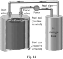
- the battery 100 also includes a storage tank 128 to store hydrogen gas, and an optional pump 130 fluidly connected between the outlet 124, through the outlet valve 126, and the storage tank 128, and where the pump 130 is configured to direct a flow of hydrogen gas from the enclosure 118 to the storage tank 128.
- the storage tank 128 is also fluidly connected to the inlet 120, through the inlet valve 122, to allow a flow of hydrogen gas from the storage tank 128 to the enclosure 118.
- Additional embodiments of this disclosure are directed to a manufacturing method of a catalytic hydrogen electrode which includes providing a conductive substrate and a deposition solution in contact with the conductive substrate, and where the deposition solution includes precursors of a bi-functional catalyst.
- the method also includes performing electrodeposition to form a coating of the bi-functional catalyst covering the conductive substrate.
- the bi-functional catalyst is a nickel-molybdenum-cobalt alloy
- the deposition solution includes a nickel-containing precursor, a molybdenum-containing precursor, and a cobalt-containing precursor.
- this example is directed to a class of battery chemistry termed as "metal-hydrogen" batteries by pairing earth-abundant transition metal cathodes (e.g., nickel, manganese, cobalt, etc .) with a low-cost, bi-functional nickel-molybdenum-cobalt alloy catalyzed hydrogen anode in an alkaline electrolyte.
- the batteries operate by redox reactions of metal oxides at the cathode and highly reversible hydrogen evolution/oxidation reactions at the anode.
- the Ni-H 2 battery exhibits a high energy density of about 140 Wh kg -1 (or more) and excellent rechargeability with negligible capacity decay over 1500 cycles (or more).
- the cost of the Ni-H 2 cells achieves as low as about $83 per kilowatt-hour, demonstrating attractive characteristics for large-sale energy storage.
- M-H 2 batteries include a redox-reactive metal cathode and a catalytic hydrogen anode in an alkaline electrolyte.
- the batteries operate by electrochemical redox-reactions at the cathode and highly reversible hydrogen evolution/oxidation reactions (HER/HOR) at the anode.
- HER/HOR highly reversible hydrogen evolution/oxidation reactions
- Successful application is performed for a nickel-molybdenum-cobalt (NiMoCo) bi-functional HER/HOR catalyst as the low-cost anode.
- Ni nickel
- Mn manganese
- Co cobalt
- the advanced nickel-hydrogen (Ni-H 2 ) cell is of particular interest because the cathode nickel hydroxide/oxyhydroxide (Ni(OH) 2 /NiOOH) reaction is highly rechargeable under alkaline conditions.
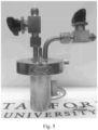
- Fig. 1a The fabrication and energy storage mechanism of the advanced Ni-H 2 battery is schematically depicted in Fig. 1a . It is constructed in a custom-made cylindrical cell by rolling a Ni(OH) 2 cathode, polymer separator and NiMoCo catalyzed anode into a steel vessel, similar to the fabrication of commercial AA batteries. An about 30% potassium hydroxide (KOH) solution is used as an electrolyte. The steel vessel is equipped with a gas inlet and outlet to remove air and to direct the hydrogen flow into and out of the cell when desired. A prototypical Ni-H 2 testing cell is shown in Fig. 5 .
- KOH potassium hydroxide
- the cathode Ni(OH) 2 is oxidized to NiOOH meanwhile hydrogen gas is evolved from the alkaline electrolyte on the anode via the NiMoCo catalyzed HER.
- the cathode NiOOH is reduced back to Ni(OH) 2 and hydrogen gas is oxidized on the anode via the NiMoCo catalyzed HOR.
- the redox reactions of the advanced Ni-H 2 cell during charge and discharge can be described as:
- Fig. 1b illustrates the electrode configuration and specification of the Ni-H 2 cell.
- the cathode was made by heavily coating micrometer sized Ni(OH) 2 spheres (Inset in Fig. 1c ) into nickel foam to form a compact electrode ( Fig. 6 ). Scanning electron microscopy (SEM) images show that the Ni(OH) 2 cathode has an average thickness of about 700 ⁇ m ( Fig. 1c ). Due to the high density of the Ni(OH) 2 microsphere, the tap density of the cathode is about 2.6 g cm -3 , corresponding to a high mass loading of about 182 mg cm -2 .
- the Ni(OH) 2 was further characterized by X-ray diffraction (XRD) to be ⁇ -phase ( Fig. 7 ), which is the most stable phase in the Ni(OH) 2 family.
- XRD X-ray diffraction
- the large thickness, high mass loading and tap density of the Ni(OH) 2 electrode are among those of industry levels, allowing the Ni-H 2 cells into practical energy storage applications.
- the anode is comprised of a three-dimensional (3D) thin layer of NiMoCo catalyst, which was directly grown on porous nickel foam without any conducting additive or binder ( Fig. 1b ).
- XRD confirmed the crystal phase of the NiMoCo alloy ( Fig. 8 ).
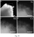
- NiMoCo comprises of many interconnected nanoparticles (Inset in Fig. 1d ). It is further disclosed by transmission electron microscopy (TEM) that the NiMoCo nanoparticles are in the range of tens of nanometers ( Fig. 9 ). The scanning transmission electron microscopy (STEM) and the elemental mapping of the NiMoCo alloy demonstrate the uniform distribution of the individual elements of Ni, Mo and Co ( Fig. 10 ).
- the developed NiMoCo electrode has some unique features to the M-H 2 battery. 1) Due to the 3D characteristic of the nickel foam, the resulting NiMoCo electrode retains the macroporous hierarchical nature ( Fig. 1d ).
- the interconnected NiMoCo nanoparticles give rise to the formation of nanopores in between, making the porous NiMoCo electrode with highly accessible surface for fast battery charge and discharge reactions.
- the generated hydrogen gas can be readily evolved on the porous anode in the charge process and be effectively oxidized in the discharge process.
- the nickel foam skeletons are interconnected virtually free-of-junction, assuring high electrical conductivity of the electrodes for good battery operation.
- Fig. 2 demonstrates the electrochemical performance of the advanced Ni-H 2 cylindrical cell using the compact Ni(OH) 2 cathode and 3D NiMoCo anode.
- the galvanostatic charge and discharge tests at a constant current of about 50 mA (about 2.78 mA cm -2 ) represent distinct charge and discharge plateaus at about 1.55 V and about 1.25 V, respectively ( Fig. 2a ), which agree well with the reaction potentials between Ni(OH) 2 /NiOOH and HER/HOR.
- the Ni-H 2 cylindrical cell can achieve high discharge capacity of about 640 mAh, which corresponds to a specific capacity of about 195 mAh g -1 (based on the mass of Ni(OH) 2 ) and areal capacity of about 35.5 mAh cm -2 .
- the advanced Ni-H 2 cell exhibits excellent rechargeability, retaining above about 95% of the initial capacity ( Fig. 2b ) and Coulombic efficiency (the ratio of discharge capacity over charge capacity, in Fig. 11 ) after 600 cycles at a current of about 100 mA (about 5.56 mA cm -2 ). Meanwhile, remarkable rate capability is achieved in the Ni-H 2 cell, as proven by charging and discharging it under different current densities ( Fig. 12 ).
- the Ni-H 2 cell can be operated under fast charge mode.
- a set of charge-discharge measurements show that the discharge capacities of the Ni-H 2 cell at current density of about 50 mA kept almost the same under different charge current densities (from about 50 mA to about 150 mA) ( Fig. 13 ).
- the energy density of the Ni-H 2 cylindrical cell is calculated to be about 140 Wh kg -1 (normalized to the mass of all components in the cell but excluding the steel vessel) which is higher than the nickel-cadmium (40-60 Wh kg -1 ) and lead-acid batteries (30-50 Wh kg -1 ).
- the energy cost of the materials utilization in the advanced Ni-H 2 cylindrical cell is estimated to be about $83 kWh -1 , achieving the DOE cost target of $100 kWh -1 for large-scale energy storage applications.
- the capital cost of the Ni-H 2 system can be further reduced by optimization of the electrode materials and the battery operation system.
- a semi-flowable battery system is proposed to manage the advanced Ni-H 2 cells for the improvement of overall cell performance.
- the semi-flowable cells are constructed by connecting one or multiple individual Ni-H 2 cells with a hydrogen storage tank (details in Supplementary Information).
- the hydrogen storage tank serves as an external energy collector and reservoir to one or more of the connected cells.
- the advanced semi-flowable configuration contributes to the system with some particular advantages. 1)
- the charge process of the semi-flowable Ni-H 2 cells operates under ambient pressure, making them less dependent on the high pressure vessel. Therefore, it provides an efficient pathway to the reduction of the manufacturing cost upon the utilization of the pressure vessel. 2)
- the ambient-pressure charge process is favorable to the charge overpotential.
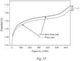
- the flowable Ni-H 2 cell For example, about 27 mV of the decrease of the charge overpotential is achieved in the flowable Ni-H 2 cell due to the kinetically favorable reaction for hydrogen generation ( Fig. 15 ). The reduction of the overpotential is believed to contribute to the improvement of the system efficiency.
- the discharge of the semi-flowable Ni-H 2 cells can be controlled by the flow of the hydrogen gas into the cells.
- the advanced semi-flowable system is tolerant to the cell overcharge/overdischarge, realized by dissipating the overcharge/overdischarge induced gases (mainly O 2 ) out of the system. 5)
- the flow of the hydrogen gas in the system is self-driven by the internal gas pressure.
- Ni-H 2 battery system is spontaneous and self-balanced in a constrained space. Moreover, the speed of gas flow is faster than a liquid and consumes less energy. This is a great advantage for the flowable Ni-H 2 battery system where a pump or other external force can be omitted, leading to the simplicity and cost reduction of the system design.
- the Ni-H 2 cells and the hydrogen tank can be separated completely for various applications. As such, the charged Ni-H 2 cells with low hydrogen pressure can be treated as dispatchable sources of electricity for better transportation without carrying the hydrogen tank. Meanwhile, the hydrogen tank with high purity hydrogen gas storage can be treated as an independent fuel resource for other applications.
- the individual cells can be electrically connected in series or parallel to provide high output voltage or current, respectively.
- Pt/C and NiMoCo exhibit significantly higher current densities than that of the nickel foam, indicating the negligible HER activity of the nickel foam and significant activity of the Pt/C and NiMoCo catalysts.
- the exceptional HER activity of NiMoCo approaches the benchmark Pt/C catalyst.
- An overpotential of about 80 mV for NiMoCo drives a hydrogen generation current density of about 10 mA cm -2 , which is highly comparable to that of the Pt/C catalyst which has an overpotential of about 71 mV.
- the applied overpotential of the NiMoCo electrode is as low as about 180 mV, making it one of the most active non-precious electrocatalysts toward HER in alkaline solutions.
- the NiMoCo demonstrates outstanding long-term stability, showing no noticeable activity degradation over about 1500 hours of hydrolysis at current density of about 20 mA cm -2 ( Fig. 3b ).
- the Pt/C catalyst shows gradual activity degradation over about 800 hours of hydrolysis, probably due to the detachment of the Pt/C from the nickel foam which is caused by generous hydrogen evolution bubbles.
- FIG. 3c shows the polarization curves of the nickel foam, Pt/C and NiMoCo on nickel foam under different gas conditions.
- the anodic current above zero is an indicator of hydrogen oxidation. It shows that the Pt/C and NiMoCo have negligible activities toward HOR under argon atmosphere, virtually because of the limited availability of hydrogen gas in the testing cell.
- Nickel foam shows no detectable HOR activity under hydrogen atmosphere. In comparison, both Pt/C and NiMoCo exhibit the typical polarization curves with large current densities under hydrogen atmosphere, indicating their excellent HOR activities.
- NiMoCo was found to have an onset potential of 0 V toward HOR, which is the same as that of the Pt/C, confirming its unprecedented HOR catalytic performance. Long-term stability tests are performed toward the HOR activity of NiMoCo. Impressively, the NiMoCo electrode shows negligible activity degradation over about 1000 hours of consecutive hydrogen oxidation ( Fig. 3d ). In contrast, the Pt/C electrode shows slight activity decay over long term ( Fig. 3d ). The outstanding HER/HOR activities of the NiMoCo make it an exceptional bi-functional hydrogen catalyst for the M-H 2 battery application.
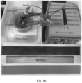
- NiMoCo catalyst as the 3D hydrogen electrode provides many advantages over a slurry coated Pt/C catalysts. 1) As compared to the costly Pt/C, the use of low-cost NiMoCo as the hydrogen catalyst can dramatically reduce the battery cost, making it highly desirable for large-scale energy storage application. 2) The electrochemical deposition of the NiMoCo catalyst on nickel foam gives rise to a 3D electrode with no carbon additive or polymer binder, which improves the electrode conductivity and also avoids the carbon oxidation induced catalyst failure or the possible catalytic poisons. 3) The DC power supplied two-electrode deposition is of large-scale fabrication ( Fig. 16 ), allowing the development of Ni-H 2 cells for large-scale applications.
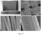
- NiMoCo is applicable to any conductive substrates.
- the NiMoCo alloys are successfully deposited onto nickel foam and foil, stainless steel mesh and foil, and carbon fiber cloth ( Fig. 17 ).
- the composition, morphology and thickness of the NiMoCo can be well controlled by the electrodeposition, which provides a general approach to the optimization of the NiMoCo catalyst and to the fabrication of other metal/metal alloys for many widespread applications.
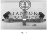
- Fig. 18 small-sized Swagelok cells are developed ( Fig. 18 ) to test a series of low-cost metals (Ni, Co, Mn, and Zn)-H 2 systems.
- the metal electrodes, separator and NiMoCo or Pt/C catalyzed hydrogen electrode are laminated in stacks for the assembly of the Swagelok cells.
- Fig. 4 presents the electrochemical performance of four different M-H 2 cells.
- the Ni-H 2 Swagelok cell was fabricated by using Ni(OH) 2 cathode and NiMoCo or Pt/C anode.
- the galvanostatic charge-discharge curves demonstrate the similar electrochemical behaviors of the Ni-H 2 Swagelok cell by the deployment of NiMoCo and Pt/C anode ( Fig. 4a ).
- the cell with the NiMoCo anode shows better discharge characteristic and a slightly higher discharge capacity.
- the Ni-H 2 Swagelok cell with the NiMoCo anode exhibits outstanding long-term cycle stability, showing negligible capacity decay over 1500 cycles ( Fig. 4b ).
- the Ni-H 2 cell with the Pt/C anode shows gradual capacity degradation over cycling.
- Fig. 4a The galvanostatic charge-discharge curves demonstrate the similar electrochemical behaviors of the Ni-H 2 Swagelok cell by the deployment of NiMoCo and Pt/C anode
- the cell with the NiMoCo anode shows better discharge characteristic and a slightly higher discharge capacity.
- the Ni-H 2 Swagelok cell with the NiMoCo anode exhibits outstanding long-term cycle stability, showing neg
- Co-H 2 Swagelok cell by using ZnCo 2 O 4 cathode ( Fig. 20 ) and the NiMoCo anode.
- the Co-H 2 cell shows distinct charge and discharge voltage plateaus in the ranges of about 1.3-1.4 V and about 1.2-1.3 V, respectively.
- the small overpotential of about 110 mV (at about 100 mAh g -1 ) is superior to that of the Ni-H 2 cell, due to the nanostructured ZnCo 2 O 4 cathode with fast charge storage kinetics.
- the consecutive charge and discharge cycling of the Co-H 2 cell demonstrates very stable long-term rechargeability, showing no capacity loss over 5000 cycles.
- the electrolytic manganese dioxide with a small amount of nickel and cobalt doping was chosen as the cathode by pairing with the NiMoCo anode ( Fig. 21 ).
- the charge-discharge profiles of the Mn-H 2 cell exhibit the similar electrochemical behavior as that of MnO 2 alkaline batteries.
- the Mn-H 2 cell shows slow capacity decay over consecutive cycling, retaining a capacity of about 100 mAh g -1 after 1200 cycles ( Fig. 19 ). Nevertheless, it is a significant improvement of the cycle stability from the Mn based alkaline batteries, demonstrating the superior capability of the Mn-H 2 cell.
- the NiMoCo electrocatalyst can be employed as a cathode for the M-H 2 cells such as Zn-H 2 cell due to its suitable redox potential of HER/HOR versus Zn plating/stripping reactions.
- the Zn-H 2 cell was fabricated by using Zn foil as the anode and NiMoCo as the cathode in the electrolyte of about 30% KOH with addition of about 0.5 M ZnO.
- the Zn-H 2 cell shows a discharge plateau of about 0.4 V ( Fig. 4e ), which corresponds to the potential difference between the Zn anode and the NiMoCo cathode.
- the Zn-H 2 cell shows no capacity decay over 1000 cycles.
- the electrochemical performance of the M-H 2 cells by the application of the NiMoCo demonstrates the remarkable electrocatalytic activity of the NiMoCo as a universal bi-functional HER/HOR catalyst in alkaline electrolyte.
- a class of metal-hydrogen batteries is developed using redox-active metal (Ni, Co, and Mn) cathode and a low-cost NiMoCo catalyzed hydrogen anode.
- the advanced Ni-H 2 cell shows a high energy density of about 140 Wh kg -1 with excellent rechargeability over 1500 cycles.
- the low energy cost of about US$83 kWh -1 achieves the DOE target of US$100 kWh -1 , which makes it desirable for the large-scale energy storage application. Further optimization of the materials and systems can be performed for improved electrochemical performance.
- a two-electrode cathodic deposition was used to synthesize NiMoCo alloys onto 3D porous nickel foam substrates.
- the deposition was conducted on a DC power supply (Dr. Meter DC Power Supply HY5020E) by taking a piece of nickel foam as cathode and titanium mesh as anode under current density of about 80 mA cm -2 with respect to the cathode.
- Dr. Meter DC Power Supply HY5020E Dr. Meter DC Power Supply HY5020E
- the deposition solution was prepared by dissolution of nickel (II) chloride hexahydrate (NiCl 2 .6H 2 O, about 11.9 g L -1 ), sodium molybdate dihydrate (Na 2 MoO 4 .2H 2 O, about 2.42 g L -1 ), cobalt (II) chloride hexahydrate (CoCl 2 .6H 2 O, about 0.35 g L -1 ), sodium bicarbonate (NaHCO 3 , about 74.77 g L -1 ) and sodium pyrophosphate tetrabasic (Na 4 P 2 O 7 , about 34.57 g L -1 ) into DI water at room temperature.
- nickel (II) chloride hexahydrate NiCl 2 .6H 2 O, about 11.9 g L -1
- sodium molybdate dihydrate Na 2 MoO 4 .2H 2 O, about 2.42 g L -1
- NiMoCo coated nickel foam was cleaned by DI water and immersed in about 10 M KOH for about 24 hours. It was then cleaned by DI water and dried in air. Subsequently, the NiMoCo coated nickel foam was annealed in a tube furnace at about 450 °C for about 1 h under forming gas atmosphere (about 95% Ar with about 5% H 2 ).
- the tube furnace was cooled naturally and the NiMoCo coated nickel foam was taken out and kept in vacuum box for further use.
- the commercially available Pt/C powder HiSPEC platinum 40% on carbon, Fuel cell store, USA
- PVDF polyvinylidene fluoride
- NMP N-Methyl-2-pyrrolidone
- the suspension was stirred for at least about 24 hours and then was subjected to a bath sonication of about 30 minutes before coating onto the nickel foam.
- the nickel foam was immersed into the Pt/C suspension for about 1 minute and then taken out for drying in vacuum oven at about 80 °C. Multiple times of the immersion-soaking-drying process were applied to increase the loading of Pt/C on the nickel foam.
- Ni(OH) 2 cathode with industrial-level mass loading of about 180 mg cm -2 was prepared by a slurry coating of Ni(OH) 2 microspheres (Panasonic) onto nickel foam.
- the ZnCo 2 O 4 cathode was grown directly onto nickel foam current collector by a hydrothermal reaction.
- zinc nitrate hexahydrate (Zn(NO 3 ) 2 .6H 2 O, about 1 mmol), cobalt (II) nitrate hexahydrate (Co(NO 3 ) 2 .6H 2 O, about 2 mmol), ammonium fluoride (NH 4 F, about 2 mmol) and urea (CO(NH 2 ) 2 , about 5 mmol) were dissolved into DI water (about 35 mL) under vigorous stirring.
- Ni and Co doped ⁇ -MnO 2 electrolytic manganese dioxide was prepared by a three-electrode deposition, where the carbon cloth, Ag/AgCl electrode and graphite rod served as working, reference and counter electrodes, respectively.
- the deposition solution was prepared by dissolving manganese (II) sulfate monohydrate (MnSO 4 .H 2 O, about 48 g L -1 ), sulfuric acid (H 2 SO 4 , about 95-98%, about 24 g L -1 ) with nickel (II) sulfate hexahydrate (NiSO 4 .6H 2 O, about 2% of MnSO 4 ) and cobalt (II) sulfate heptahydrate (CoSO 4 .7H 2 O, about 2% of MnSO 4 ) into DI water.
- a current density of about 20 mA cm -2 was applied to deposit Ni and Co doped MnO 2 onto the conductive carbon cloth at temperature of 90 ( ⁇ 3) °C for about 5 minutes. Afterwards, the sample was cleaned by DI water and allowed to dry in vacuum.
- the Swagelok cell was built up by clamping two KF to Swagelok adapters in a PTFE-centered O-ring ( Fig. 18 ).
- the adapters were equipped with inlet and outlet valves to remove trapped air from the cell and to connect it with external hydrogen tank for the semi-flowable cell when desired.
- the cathode Ni(OH) 2 on nickel foam, ZnCo 2 O 4 on nickel foam, EMD on carbon cloth
- separator ZYK-15, Zircar Zirconia, Inc. USA
- the anode NiMoCo/Pt/C on nickel foam
- a thin layer of insulating PTFE film was inserted between the stainless steel adapter and the aluminum clamp to avoid the contact of the cathode and the anode.
- the electrolyte was freshly prepared by dissolving about 30 wt.% KOH in DI water.
- the advanced Ni-H 2 cylindrical cell was constructed by clamping a KF to Swagelok adapter with a stainless steel cylinder in a PTFE-centered O-ring ( Fig. 5 ).
- the adapter and the stainless steel cylinder were machined in a machine shop.
- the adapter was connected with a three-way valve on its outside, while its inside was welded with a steel rod which serves as cathode terminal.
- a piece of Ni(OH) 2 electrode wrapping with polymer separator (Freudenberg, Germany) on its both sides and a piece of NiMoCo anode were stacked and surrounded on the steel rod to make a cylinder-like cell configuration.
- the cathode was spot welded to the stainless steel rod for good electronic conductivity.
- the electrodes were then put into the stainless steel cylinder where the NiMoCo anode was directly contacted with the cylinder and served as anode terminal.
- a freshly prepared about 30 wt % KOH electrolyte was added to the cell.
- the Ni-H 2 cylindrical cell was purged with high purity hydrogen gas (about 99.99%, Airgas) to remove the trapped air.
- the sealed cell was allowed to sit for over about 12 hours before the electrochemical measurements.
- the semi-flowable Ni-H 2 battery system was formed by connecting one of more individual Ni-H 2 cells with a hydrogen storage tank through steel pipelines ( Fig. 14 ).
- the hydrogen storage tank has a higher pressure than what is specified for the Ni-H 2 cell.
- the cathode Ni(OH) 2 is oxidized to NiOOH meanwhile hydrogen gas is generated on the anode via the NiMoCo catalyzed hydrogen evolution reaction.
- the gas inlet valve is kept off while the outlet valve is kept on in the whole charge process, in order to let the generated gas flow out of the cell to the hydrogen storage tank.
- the charge of the semi-flowable Ni-H 2 battery was conducted under ambient pressure.
- the gas outlet valve is turned off while the inlet valve is turned on to fill the cell with hydrogen.
- the cathode is therefore reduced back to Ni(OH) 2 and hydrogen gas is oxidized on the anode via the NiMoCo catalyzed hydrogen oxidation reaction in the discharge process.
- the electrochemical tests of the M-H 2 batteries were conducted in Biologic VMP3 multi-channel electrochemical workstations (Bio-Logic Inc. France) and LandHe battery testers (Wuhan, China) at room temperature. Galvanostatic charge-discharge measurements were performed by charging the cells at different currents to a set cut-off capacity and discharging them to a set cut-off voltage.
- the electrocatalytic activity of the NiMoCo and Pt/C anodes toward HER was conducted in a three-electrode configuration by taking the NiMoCo or Pt/C on nickel foam as a working electrode, saturated calomel electrode (SCE) as a reference electrode and a graphite rod as a counter electrode.
- Linear sweep voltammetry curve was recorded at about 1 mV/s between about -0.9 and about -1.6 V (vs. SCE).
- the electrocatalytic activity of the NiMoCo and Pt/C anodes toward HOR was conducted in a two-electrode configuration by using the NiMoCo or Pt/C on nickel foam as a working electrode and a graphite rod as a counter electrode.
- the fabrication of the HOR test cell is the same as that of the Swagelok cell.
- the catalysts were tested under hydrogen and argon atmosphere in the sealed Swagelok cell separately. Linear sweep voltammetry curve was recorded at about 1 mV/s between about -0.1 and about 0.4 V. Long-term chronoamperometric stability test was conducted under a constant potential of about 0.3 V.
- the materials were characterized by X-ray diffraction (XRD), scanning electron microscopy (SEM) and transmission electron microscopy (TEM).
- XRD X-ray diffraction
- SEM scanning electron microscopy
- TEM transmission electron microscopy
- the crystallinity and structure of the materials were determined by PANalytical X'Pert diffractometer using copper K-edge X-rays.
- the morphology of the products was observed by FEI XL30 Sirion SEM.
- TEM and energy-dispersive X-ray spectroscopy (EDX) were conducted on FEI Tecnai G2 F20 X-TWIN TEM.
- C ⁇ i P i m i / E d
- C the capital energy cost per discharge energy in unit of US dollar per kilowatt-hour (US$ kWh -1 )
- P i the specific cost of each component in US$ kg -1
- m i the mass of the specific component in kg
- E d the discharge energy in kWh.
- the price of the transition metals Ni: US$14 kg -1 , Mo: US$26 kg -1 , Co: US$90 kg -1 ) are obtained from www.infomine.com.
- the terms “substantially,” “substantial,” and “about” are used to describe and account for small variations.
- the terms can refer to instances in which the event or circumstance occurs precisely as well as instances in which the event or circumstance occurs to a close approximation.
- the terms can encompass a range of variation of less than or equal to ⁇ 10% of that numerical value, such as less than or equal to ⁇ 5%, less than or equal to ⁇ 4%, less than or equal to ⁇ 3%, less than or equal to ⁇ 2%, less than or equal to ⁇ 1%, less than or equal to ⁇ 0.5%, less than or equal to ⁇ 0.1%, or less than or equal to ⁇ 0.05%.
- a size of an object that is circular or spherical can refer to a diameter of the object.
- a size of the object can refer to a diameter of a corresponding circular or spherical object, where the corresponding circular or spherical object exhibits or has a particular set of derivable or measurable characteristics that are substantially the same as those of the non-circular or non-spherical object.
- the objects can have a distribution of sizes around the particular size.
- a size of a set of objects can refer to a typical size of a distribution of sizes, such as an average size, a median size, or a peak size.
- connection refers to an operational coupling or linking.
- Connected objects can be directly coupled to one another or can be indirectly coupled to one another, such as via one or more other objects.
- range format is used for convenience and brevity and should be understood flexibly to include numerical values explicitly specified as limits of a range, but also to include all individual numerical values or sub-ranges encompassed within that range as if each numerical value and sub-range is explicitly specified.
- a range of about 1 to about 200 should be understood to include the explicitly recited limits of about 1 and about 200, but also to include individual values such as about 2, about 3, and about 4, and sub-ranges such as about 10 to about 50, about 20 to about 100, and so forth.
Landscapes
- Chemical & Material Sciences (AREA)
- Chemical Kinetics & Catalysis (AREA)
- Electrochemistry (AREA)
- General Chemical & Material Sciences (AREA)
- Engineering & Computer Science (AREA)
- Manufacturing & Machinery (AREA)
- Materials Engineering (AREA)
- Life Sciences & Earth Sciences (AREA)
- Sustainable Development (AREA)
- Sustainable Energy (AREA)
- Ceramic Engineering (AREA)
- Battery Electrode And Active Subsutance (AREA)
- Cell Electrode Carriers And Collectors (AREA)
- Inert Electrodes (AREA)
- Secondary Cells (AREA)
- Management, Administration, Business Operations System, And Electronic Commerce (AREA)
Claims (10)
- Metall-Wasserstoff-Batterie, umfassend:eine erste Elektrode;eine zweite Elektrode, die während des Ladens Wasserstoffgas erzeugt und während des Entladens Wasserstoffgas oxidiert; undeinen Elektrolyten, der zwischen der ersten Elektrode und der zweiten Elektrode angeordnet ist, wobei die zweite Elektrode ein zweites leitfähiges Substrat, das einen Nickelschaum umfasst, und eine zweite Beschichtung, die das zweite leitfähige Substrat bedeckt, beinhaltet, wobei die zweite Beschichtung einen bifunktionellen Katalysator beinhaltet, der eine Nickel-Molybdän-Kobalt-Legierung umfasst, wobei der bifunktionelle Katalysator sowohl die Wasserstoffentwicklungsreaktion als auch die Wasserstoffoxidationsreaktion an der zweiten Elektrode katalysiert, dadurch gekennzeichnet, dass der bifunktionelle Katalysator in einer Form von miteinander verbundenen Nanopartikeln ist, die Nanoporen aufweisen, die zwischen den miteinander verbundenen Nanopartikeln ausgebildet sind.
- Metall-Wasserstoff-Batterie nach Anspruch 1, wobei die erste Elektrode ein erstes leitfähiges Substrat und eine erste Beschichtung, die das erste leitfähige Substrat bedeckt, beinhaltet und die erste Beschichtung ein redoxreaktives Material beinhaltet, das ein Übergangsmetall beinhaltet.
- Metall-Wasserstoff-Batterie nach Anspruch 2, wobei das erste leitfähige Substrat:porös ist odereinen Metallschaum oder einen Metalllegierungsschaum beinhaltet.
- Metall-Wasserstoff-Batterie nach Anspruch 2, wobei das Übergangsmetall eines von Nickel, Kobalt oder Mangan beinhaltet.
- Metall-Wasserstoff-Batterie nach einem der Ansprüche 1 oder 2, wobei die erste Elektrode eine Metallfolie beinhaltet, die ein Übergangsmetall beinhaltet.
- Metall-Wasserstoff-Batterie nach einem der Ansprüche 1-5, wobei der Elektrolyt:ein wässriger Elektrolyt oderalkalisch ist.
- Metall-Wasserstoff-Batterie nach einem der Ansprüche 1-6, weiterhin umfassend ein Gehäuse, innerhalb dessen die erste Elektrode, die zweite Elektrode und der Elektrolyt angeordnet sind, und wobei das Gehäuse ein Einlassventil, einen Einlass, der mit dem Einlassventil fluidverbunden ist, ein Auslassventil und einen Auslass, der mit dem Auslassventil fluidverbunden ist beinhaltet; und optionaleinen Speichertank, um Wasserstoffgas zu speichern; undeine Pumpe, die zwischen dem Auslass durch das Auslassventil und dem Speichertank fluidverbunden ist.
- Metall-Wasserstoff-Batterie nach Anspruch 1, wobei:die erste Elektrode eine Kathode ist, die ein redoxreaktives Material beinhaltet, das ein Übergangsmetall beinhaltet;die zweite Elektrode eine katalytische Wasserstoffanode ist, die den bifunktionellen Katalysator beinhaltet; undder Elektrolyt alkalisch ist.
- Verfahren zur Herstellung der Metall-Wasserstoff-Batterie nach einem der vorhergehenden Ansprüche, wobei das Verfahren ein Ausbilden der zweiten Elektrode durch:Bereitstellen des zweiten leitfähigen Substrats und einer Abscheidungslösung in Kontakt mit dem zweiten leitfähigen Substrat, wobei die Abscheidungslösung Vorläufer des bifunktionellen Katalysators beinhaltet; undDurchführen einer elektrolytischen Abscheidung, um eine Beschichtung aus dem bifunktionellen Katalysator, die das zweite leitfähige Substrat bedeckt, auszubilden, umfasst.
- Verfahren nach Anspruch 9, wobei die Vorläufer einen nickelhaltigen Vorläufer, einem molybdänhaltigen Vorläufer und einen kobalthaltigen Vorläufer beinhalten.
Applications Claiming Priority (2)
| Application Number | Priority Date | Filing Date | Title |
|---|---|---|---|
| US201762544508P | 2017-08-11 | 2017-08-11 | |
| PCT/US2018/045816 WO2019032704A1 (en) | 2017-08-11 | 2018-08-08 | METAL-HYDROGEN BATTERIES OF LARGE SCALE ENERGY ACCUMULATION |
Publications (3)
| Publication Number | Publication Date |
|---|---|
| EP3665739A1 EP3665739A1 (de) | 2020-06-17 |
| EP3665739A4 EP3665739A4 (de) | 2021-04-28 |
| EP3665739B1 true EP3665739B1 (de) | 2024-05-22 |
Family
ID=65271635
Family Applications (1)
| Application Number | Title | Priority Date | Filing Date |
|---|---|---|---|
| EP18845281.7A Active EP3665739B1 (de) | 2017-08-11 | 2018-08-08 | Metall-wasserstoff-batterien für energiespeicherung im grossen massstab |
Country Status (10)
| Country | Link |
|---|---|
| US (1) | US11855294B2 (de) |
| EP (1) | EP3665739B1 (de) |
| JP (1) | JP7345858B2 (de) |
| KR (1) | KR102641151B1 (de) |
| CN (1) | CN111033883A (de) |
| AU (1) | AU2018313823B2 (de) |
| CA (1) | CA3068606A1 (de) |
| MX (1) | MX2020001452A (de) |
| SG (1) | SG11202000107RA (de) |
| WO (1) | WO2019032704A1 (de) |
Families Citing this family (15)
| Publication number | Priority date | Publication date | Assignee | Title |
|---|---|---|---|---|
| CN111357149B (zh) * | 2017-12-26 | 2024-06-07 | 信越聚合物株式会社 | 散热结构和具有其的电池 |
| US10811711B2 (en) | 2018-11-20 | 2020-10-20 | University Of Delaware | Electrochemical devices and fuel cell systems |
| US12191502B2 (en) * | 2019-04-02 | 2025-01-07 | Eenotech, Inc. | pH-universal aqueous rechargeable hydrogen batteries |
| CN111515380B (zh) * | 2020-05-11 | 2022-04-29 | 安泰科技股份有限公司 | 一种高容量镁基复合储氢材料及其制备方法 |
| CN111847400A (zh) * | 2020-05-14 | 2020-10-30 | 清华大学 | 制备非贵金属氢燃料电池负极材料的方法 |
| IL298364A (en) | 2020-05-20 | 2023-01-01 | Univ Delaware | Electrochemically driven carbon dioxide separator |
| EP3916123A1 (de) * | 2020-05-29 | 2021-12-01 | 2706649 Ontario Ltd | Aktives element, verfahren zu seiner herstellung und elektrochemische vorrichtung |
| CN111769297B (zh) * | 2020-07-17 | 2022-08-16 | 郑州佛光发电设备股份有限公司 | 铝空气电池阴极催化剂及其制备方法 |
| EP3957599A1 (de) | 2020-08-21 | 2022-02-23 | 2706649 Ontario Ltd | Wasserstofferzeugungselement, verfahren zu seiner herstellung und seine verwendung |
| US12087951B2 (en) * | 2020-10-12 | 2024-09-10 | Peter HERMANSEN | Electrochemical cell integrates electrolysis and fuel cell functions |
| WO2022246747A1 (zh) * | 2021-05-27 | 2022-12-01 | 中国科学技术大学 | 金属-氢气电池及其制备方法 |
| KR102949170B1 (ko) * | 2021-06-24 | 2026-04-07 | 에너베뉴 인코포레이티드 | 금속 수소 배터리용 전극 및 그 제조방법 |
| US12586826B2 (en) | 2021-11-10 | 2026-03-24 | EnerVenue Holdings, Ltd. | Method for operating a metal-hydrogen battery |
| US12107249B2 (en) | 2022-08-29 | 2024-10-01 | EnerVenue Inc. | Nickel-hydrogen battery configurations for grid-scale energy storage |
| US20240097241A1 (en) * | 2022-09-19 | 2024-03-21 | EnerVenue, Inc | Facility for High Capacity Storage Using Metal Hydrogen Batteries |
Family Cites Families (24)
| Publication number | Priority date | Publication date | Assignee | Title |
|---|---|---|---|---|
| US3544375A (en) * | 1967-05-22 | 1970-12-01 | Samuel Ruben | Rechargeable fuel cell |
| US4159367A (en) | 1978-06-29 | 1979-06-26 | Yardney Electric Corporation | Hydrogen electrochemical cell and rechargeable metal-hydrogen battery |
| US4460660A (en) * | 1982-12-22 | 1984-07-17 | Rca Corporation | Negative hydrogen electrode comprising an alloy palladium and rutherium |
| US4567119A (en) | 1984-03-12 | 1986-01-28 | Hughes Aircraft Company | Nickel-hydrogen bipolar battery |
| US5618392A (en) | 1991-10-31 | 1997-04-08 | Tanaka Kikinzoku Kogyo K.K. | Gas diffusion electrode |
| JP3171642B2 (ja) * | 1992-02-28 | 2001-05-28 | 田中貴金属工業株式会社 | ガス拡散電極 |
| US5695530A (en) * | 1994-03-14 | 1997-12-09 | Hong; Kuochih | Method for making high charging efficiency and fast oxygen recombination rechargeable hydride batteries |
| CA2424861A1 (en) * | 2000-10-02 | 2003-03-13 | Tohoku Techno Arch Co., Ltd. | Method of absorption-desorption of hydrogen storage alloy and hydrogen storage alloy and fuel cell using said method |
| US7645543B2 (en) * | 2002-10-15 | 2010-01-12 | Polyplus Battery Company | Active metal/aqueous electrochemical cells and systems |
| CN101521277A (zh) | 2004-01-08 | 2009-09-02 | 双向电池公司 | 用于镍电极的正极活性材料 |
| US20060293173A1 (en) * | 2005-06-28 | 2006-12-28 | Qinglin Zhang | Hydrogen generation catalysts and systems for hydrogen generation |
| US20080280190A1 (en) * | 2005-10-20 | 2008-11-13 | Robert Brian Dopp | Electrochemical catalysts |
| US8481530B2 (en) | 2006-12-01 | 2013-07-09 | The Research Foundation Of State University Of New York | 3β-hydroxysteroid dehydrogenase inhibitors |
| JP2009221072A (ja) * | 2008-03-18 | 2009-10-01 | Hitachi Maxell Ltd | 水素供給用カートリッジおよび燃料電池発電システム |
| KR101512034B1 (ko) * | 2010-01-25 | 2015-04-14 | 라모트 앳 텔-아비브 유니버시티 리미티드 | 연료 전지용 촉매 및 전극 |
| WO2011112992A1 (en) * | 2010-03-12 | 2011-09-15 | Energ2, Inc. | Mesoporous carbon materials comprising bifunctional catalysts |
| KR101373092B1 (ko) * | 2010-04-05 | 2014-03-13 | 삼성에스디아이 주식회사 | 연료 전지용 전극 촉매, 이를 포함하는 연료 전지용 막-전극 어셈블리 및 연료 전지 시스템 |
| CN102534283A (zh) * | 2010-12-10 | 2012-07-04 | 北京有色金属研究总院 | 一种多元合金泡沫材料及其制备方法 |
| KR20140039147A (ko) | 2011-01-28 | 2014-04-01 | 중웨이 첸 | 금속 공기 배터리/연료 전지용 코어-쉘 구조의 이작용성 촉매 |
| US20130344407A1 (en) * | 2012-06-25 | 2013-12-26 | Eveready Battery Company, Inc. | Hydrogen Generator and Method of Controlling Reaction |
| CN104798247A (zh) | 2012-09-21 | 2015-07-22 | 丹麦技术大学 | 一种可充电的碳-氧电池 |
| CN104981923B (zh) * | 2013-02-01 | 2018-09-11 | 株式会社日本触媒 | 电极前体、电极以及电池 |
| US20170342578A1 (en) * | 2014-11-11 | 2017-11-30 | William Marsh Rice University | A new class of electrocatalysts |
| CN106119652B (zh) * | 2016-06-21 | 2019-01-15 | 安泰科技股份有限公司 | 镍氢电池用La-Mg-Ni系储氢合金及其制备方法 |
-
2018
- 2018-08-08 US US16/058,607 patent/US11855294B2/en active Active
- 2018-08-08 SG SG11202000107RA patent/SG11202000107RA/en unknown
- 2018-08-08 CN CN201880050711.6A patent/CN111033883A/zh active Pending
- 2018-08-08 CA CA3068606A patent/CA3068606A1/en active Pending
- 2018-08-08 MX MX2020001452A patent/MX2020001452A/es unknown
- 2018-08-08 EP EP18845281.7A patent/EP3665739B1/de active Active
- 2018-08-08 KR KR1020207005205A patent/KR102641151B1/ko active Active
- 2018-08-08 WO PCT/US2018/045816 patent/WO2019032704A1/en not_active Ceased
- 2018-08-08 JP JP2020505397A patent/JP7345858B2/ja active Active
- 2018-08-08 AU AU2018313823A patent/AU2018313823B2/en active Active
Also Published As
| Publication number | Publication date |
|---|---|
| AU2018313823B2 (en) | 2023-09-28 |
| EP3665739A1 (de) | 2020-06-17 |
| KR102641151B1 (ko) | 2024-02-28 |
| JP2020530647A (ja) | 2020-10-22 |
| CA3068606A1 (en) | 2019-02-14 |
| US11855294B2 (en) | 2023-12-26 |
| MX2020001452A (es) | 2020-03-20 |
| AU2018313823A1 (en) | 2020-01-23 |
| US20190051907A1 (en) | 2019-02-14 |
| BR112020001152A2 (pt) | 2020-07-21 |
| EP3665739A4 (de) | 2021-04-28 |
| SG11202000107RA (en) | 2020-02-27 |
| JP7345858B2 (ja) | 2023-09-19 |
| WO2019032704A1 (en) | 2019-02-14 |
| KR20200030597A (ko) | 2020-03-20 |
| CN111033883A (zh) | 2020-04-17 |
Similar Documents
| Publication | Publication Date | Title |
|---|---|---|
| US11855294B2 (en) | Metal-hydrogen batteries for large-scale energy storage | |
| Li et al. | An amorphous trimetallic (Ni–Co–Fe) hydroxide-sheathed 3D bifunctional electrode for superior oxygen evolution and high-performance cable-type flexible zinc–air batteries | |
| Wu et al. | Ultrastable NiFeOOH/NiFe/Ni electrocatalysts prepared by in-situ electro-oxidation for oxygen evolution reaction at large current density | |
| Shang et al. | Achieving high energy density and efficiency through integration: progress in hybrid zinc batteries | |
| JP7449600B2 (ja) | 固体-液体-気体反応を伴う超安定な再充電可能なマンガン電池 | |
| Li et al. | Porous phosphorus-rich CoP3/CoSnO2 hybrid nanocubes for high-performance Zn-air batteries | |
| Bansal et al. | Silicon–air batteries: progress, applications and challenges | |
| JP2006512729A (ja) | 導電性ポリマーバインダーを用いた活性電極組成物 | |
| AU2020252206B2 (en) | pH-universal aqueous rechargeable hydrogen batteries | |
| HK40028243A (en) | Metal-hydrogen batteries for large-scale energy storage | |
| Sripallawit et al. | Cathodized Stainless Steel Mesh for Binder-Free NiFe2O4/NiFe Layer Double Hydroxides Oxygen Evolution Reaction Electrode | |
| Khor et al. | Materials today energy | |
| BR112020001152B1 (pt) | Bateria de hidrogênio metálico e método de fabricação de segundo eletrodo | |
| He et al. | New Design of Zinc–Air Batteries | |
| Xiong | Electrodeposited Electrocatalysts For Rechargeable Zinc-air Batteries | |
| JP2024500702A (ja) | エネルギー装置 | |
| Zou et al. | A Self-Supported Co-Mn Spinel Electrode for Alkaline Hybrid Zinc Battery with High Charge-Discharge Efficiency of 86% |
Legal Events
| Date | Code | Title | Description |
|---|---|---|---|
| STAA | Information on the status of an ep patent application or granted ep patent |
Free format text: STATUS: THE INTERNATIONAL PUBLICATION HAS BEEN MADE |
|
| PUAI | Public reference made under article 153(3) epc to a published international application that has entered the european phase |
Free format text: ORIGINAL CODE: 0009012 |
|
| STAA | Information on the status of an ep patent application or granted ep patent |
Free format text: STATUS: REQUEST FOR EXAMINATION WAS MADE |
|
| 17P | Request for examination filed |
Effective date: 20200102 |
|
| AK | Designated contracting states |
Kind code of ref document: A1 Designated state(s): AL AT BE BG CH CY CZ DE DK EE ES FI FR GB GR HR HU IE IS IT LI LT LU LV MC MK MT NL NO PL PT RO RS SE SI SK SM TR |
|
| AX | Request for extension of the european patent |
Extension state: BA ME |
|
| DAV | Request for validation of the european patent (deleted) | ||
| DAX | Request for extension of the european patent (deleted) | ||
| A4 | Supplementary search report drawn up and despatched |
Effective date: 20210331 |
|
| RIC1 | Information provided on ipc code assigned before grant |
Ipc: H01M 12/08 20060101AFI20210325BHEP Ipc: H01M 4/86 20060101ALI20210325BHEP Ipc: H01M 4/90 20060101ALI20210325BHEP Ipc: H01M 4/134 20100101ALI20210325BHEP Ipc: H01M 4/80 20060101ALI20210325BHEP Ipc: H01M 8/04082 20160101ALI20210325BHEP Ipc: H01M 8/04089 20160101ALI20210325BHEP Ipc: H01M 4/88 20060101ALI20210325BHEP Ipc: H01M 4/98 20060101ALI20210325BHEP |
|
| STAA | Information on the status of an ep patent application or granted ep patent |
Free format text: STATUS: EXAMINATION IS IN PROGRESS |
|
| 17Q | First examination report despatched |
Effective date: 20221117 |
|
| P01 | Opt-out of the competence of the unified patent court (upc) registered |
Effective date: 20230530 |
|
| GRAP | Despatch of communication of intention to grant a patent |
Free format text: ORIGINAL CODE: EPIDOSNIGR1 |
|
| STAA | Information on the status of an ep patent application or granted ep patent |
Free format text: STATUS: GRANT OF PATENT IS INTENDED |
|
| INTG | Intention to grant announced |
Effective date: 20231218 |
|
| GRAS | Grant fee paid |
Free format text: ORIGINAL CODE: EPIDOSNIGR3 |
|
| GRAA | (expected) grant |
Free format text: ORIGINAL CODE: 0009210 |
|
| STAA | Information on the status of an ep patent application or granted ep patent |
Free format text: STATUS: THE PATENT HAS BEEN GRANTED |
|
| AK | Designated contracting states |
Kind code of ref document: B1 Designated state(s): AL AT BE BG CH CY CZ DE DK EE ES FI FR GB GR HR HU IE IS IT LI LT LU LV MC MK MT NL NO PL PT RO RS SE SI SK SM TR |
|
| REG | Reference to a national code |
Ref country code: GB Ref legal event code: FG4D |
|
| REG | Reference to a national code |
Ref country code: CH Ref legal event code: EP |
|
| REG | Reference to a national code |
Ref country code: DE Ref legal event code: R096 Ref document number: 602018069873 Country of ref document: DE |
|
| REG | Reference to a national code |
Ref country code: IE Ref legal event code: FG4D |
|
| REG | Reference to a national code |
Ref country code: LT Ref legal event code: MG9D |
|
| REG | Reference to a national code |
Ref country code: NL Ref legal event code: MP Effective date: 20240522 |
|
| PG25 | Lapsed in a contracting state [announced via postgrant information from national office to epo] |
Ref country code: IS Free format text: LAPSE BECAUSE OF FAILURE TO SUBMIT A TRANSLATION OF THE DESCRIPTION OR TO PAY THE FEE WITHIN THE PRESCRIBED TIME-LIMIT Effective date: 20240922 |
|
| PG25 | Lapsed in a contracting state [announced via postgrant information from national office to epo] |
Ref country code: BG Free format text: LAPSE BECAUSE OF FAILURE TO SUBMIT A TRANSLATION OF THE DESCRIPTION OR TO PAY THE FEE WITHIN THE PRESCRIBED TIME-LIMIT Effective date: 20240522 |
|
| PG25 | Lapsed in a contracting state [announced via postgrant information from national office to epo] |
Ref country code: HR Free format text: LAPSE BECAUSE OF FAILURE TO SUBMIT A TRANSLATION OF THE DESCRIPTION OR TO PAY THE FEE WITHIN THE PRESCRIBED TIME-LIMIT Effective date: 20240522 Ref country code: FI Free format text: LAPSE BECAUSE OF FAILURE TO SUBMIT A TRANSLATION OF THE DESCRIPTION OR TO PAY THE FEE WITHIN THE PRESCRIBED TIME-LIMIT Effective date: 20240522 |
|
| PG25 | Lapsed in a contracting state [announced via postgrant information from national office to epo] |
Ref country code: GR Free format text: LAPSE BECAUSE OF FAILURE TO SUBMIT A TRANSLATION OF THE DESCRIPTION OR TO PAY THE FEE WITHIN THE PRESCRIBED TIME-LIMIT Effective date: 20240823 |
|
| PG25 | Lapsed in a contracting state [announced via postgrant information from national office to epo] |
Ref country code: PT Free format text: LAPSE BECAUSE OF FAILURE TO SUBMIT A TRANSLATION OF THE DESCRIPTION OR TO PAY THE FEE WITHIN THE PRESCRIBED TIME-LIMIT Effective date: 20240923 |
|
| REG | Reference to a national code |
Ref country code: AT Ref legal event code: MK05 Ref document number: 1689523 Country of ref document: AT Kind code of ref document: T Effective date: 20240522 |
|
| PG25 | Lapsed in a contracting state [announced via postgrant information from national office to epo] |
Ref country code: NL Free format text: LAPSE BECAUSE OF FAILURE TO SUBMIT A TRANSLATION OF THE DESCRIPTION OR TO PAY THE FEE WITHIN THE PRESCRIBED TIME-LIMIT Effective date: 20240522 |
|
| PG25 | Lapsed in a contracting state [announced via postgrant information from national office to epo] |
Ref country code: ES Free format text: LAPSE BECAUSE OF FAILURE TO SUBMIT A TRANSLATION OF THE DESCRIPTION OR TO PAY THE FEE WITHIN THE PRESCRIBED TIME-LIMIT Effective date: 20240522 |
|
| PG25 | Lapsed in a contracting state [announced via postgrant information from national office to epo] |
Ref country code: AT Free format text: LAPSE BECAUSE OF FAILURE TO SUBMIT A TRANSLATION OF THE DESCRIPTION OR TO PAY THE FEE WITHIN THE PRESCRIBED TIME-LIMIT Effective date: 20240522 |
|
| PG25 | Lapsed in a contracting state [announced via postgrant information from national office to epo] |
Ref country code: PL Free format text: LAPSE BECAUSE OF FAILURE TO SUBMIT A TRANSLATION OF THE DESCRIPTION OR TO PAY THE FEE WITHIN THE PRESCRIBED TIME-LIMIT Effective date: 20240522 |
|
| PG25 | Lapsed in a contracting state [announced via postgrant information from national office to epo] |
Ref country code: LV Free format text: LAPSE BECAUSE OF FAILURE TO SUBMIT A TRANSLATION OF THE DESCRIPTION OR TO PAY THE FEE WITHIN THE PRESCRIBED TIME-LIMIT Effective date: 20240522 |
|
| PG25 | Lapsed in a contracting state [announced via postgrant information from national office to epo] |
Ref country code: PT Free format text: LAPSE BECAUSE OF FAILURE TO SUBMIT A TRANSLATION OF THE DESCRIPTION OR TO PAY THE FEE WITHIN THE PRESCRIBED TIME-LIMIT Effective date: 20240923 Ref country code: PL Free format text: LAPSE BECAUSE OF FAILURE TO SUBMIT A TRANSLATION OF THE DESCRIPTION OR TO PAY THE FEE WITHIN THE PRESCRIBED TIME-LIMIT Effective date: 20240522 Ref country code: NO Free format text: LAPSE BECAUSE OF FAILURE TO SUBMIT A TRANSLATION OF THE DESCRIPTION OR TO PAY THE FEE WITHIN THE PRESCRIBED TIME-LIMIT Effective date: 20240822 Ref country code: NL Free format text: LAPSE BECAUSE OF FAILURE TO SUBMIT A TRANSLATION OF THE DESCRIPTION OR TO PAY THE FEE WITHIN THE PRESCRIBED TIME-LIMIT Effective date: 20240522 Ref country code: LV Free format text: LAPSE BECAUSE OF FAILURE TO SUBMIT A TRANSLATION OF THE DESCRIPTION OR TO PAY THE FEE WITHIN THE PRESCRIBED TIME-LIMIT Effective date: 20240522 Ref country code: IS Free format text: LAPSE BECAUSE OF FAILURE TO SUBMIT A TRANSLATION OF THE DESCRIPTION OR TO PAY THE FEE WITHIN THE PRESCRIBED TIME-LIMIT Effective date: 20240922 Ref country code: HR Free format text: LAPSE BECAUSE OF FAILURE TO SUBMIT A TRANSLATION OF THE DESCRIPTION OR TO PAY THE FEE WITHIN THE PRESCRIBED TIME-LIMIT Effective date: 20240522 Ref country code: GR Free format text: LAPSE BECAUSE OF FAILURE TO SUBMIT A TRANSLATION OF THE DESCRIPTION OR TO PAY THE FEE WITHIN THE PRESCRIBED TIME-LIMIT Effective date: 20240823 Ref country code: FI Free format text: LAPSE BECAUSE OF FAILURE TO SUBMIT A TRANSLATION OF THE DESCRIPTION OR TO PAY THE FEE WITHIN THE PRESCRIBED TIME-LIMIT Effective date: 20240522 Ref country code: ES Free format text: LAPSE BECAUSE OF FAILURE TO SUBMIT A TRANSLATION OF THE DESCRIPTION OR TO PAY THE FEE WITHIN THE PRESCRIBED TIME-LIMIT Effective date: 20240522 Ref country code: BG Free format text: LAPSE BECAUSE OF FAILURE TO SUBMIT A TRANSLATION OF THE DESCRIPTION OR TO PAY THE FEE WITHIN THE PRESCRIBED TIME-LIMIT Effective date: 20240522 Ref country code: AT Free format text: LAPSE BECAUSE OF FAILURE TO SUBMIT A TRANSLATION OF THE DESCRIPTION OR TO PAY THE FEE WITHIN THE PRESCRIBED TIME-LIMIT Effective date: 20240522 Ref country code: RS Free format text: LAPSE BECAUSE OF FAILURE TO SUBMIT A TRANSLATION OF THE DESCRIPTION OR TO PAY THE FEE WITHIN THE PRESCRIBED TIME-LIMIT Effective date: 20240822 |
|
| PG25 | Lapsed in a contracting state [announced via postgrant information from national office to epo] |
Ref country code: DK Free format text: LAPSE BECAUSE OF FAILURE TO SUBMIT A TRANSLATION OF THE DESCRIPTION OR TO PAY THE FEE WITHIN THE PRESCRIBED TIME-LIMIT Effective date: 20240522 |
|
| PG25 | Lapsed in a contracting state [announced via postgrant information from national office to epo] |
Ref country code: EE Free format text: LAPSE BECAUSE OF FAILURE TO SUBMIT A TRANSLATION OF THE DESCRIPTION OR TO PAY THE FEE WITHIN THE PRESCRIBED TIME-LIMIT Effective date: 20240522 |
|
| PG25 | Lapsed in a contracting state [announced via postgrant information from national office to epo] |
Ref country code: CZ Free format text: LAPSE BECAUSE OF FAILURE TO SUBMIT A TRANSLATION OF THE DESCRIPTION OR TO PAY THE FEE WITHIN THE PRESCRIBED TIME-LIMIT Effective date: 20240522 |
|
| PG25 | Lapsed in a contracting state [announced via postgrant information from national office to epo] |
Ref country code: RO Free format text: LAPSE BECAUSE OF FAILURE TO SUBMIT A TRANSLATION OF THE DESCRIPTION OR TO PAY THE FEE WITHIN THE PRESCRIBED TIME-LIMIT Effective date: 20240522 Ref country code: SK Free format text: LAPSE BECAUSE OF FAILURE TO SUBMIT A TRANSLATION OF THE DESCRIPTION OR TO PAY THE FEE WITHIN THE PRESCRIBED TIME-LIMIT Effective date: 20240522 |
|
| PG25 | Lapsed in a contracting state [announced via postgrant information from national office to epo] |
Ref country code: SM Free format text: LAPSE BECAUSE OF FAILURE TO SUBMIT A TRANSLATION OF THE DESCRIPTION OR TO PAY THE FEE WITHIN THE PRESCRIBED TIME-LIMIT Effective date: 20240522 |
|
| PG25 | Lapsed in a contracting state [announced via postgrant information from national office to epo] |
Ref country code: SM Free format text: LAPSE BECAUSE OF FAILURE TO SUBMIT A TRANSLATION OF THE DESCRIPTION OR TO PAY THE FEE WITHIN THE PRESCRIBED TIME-LIMIT Effective date: 20240522 Ref country code: SK Free format text: LAPSE BECAUSE OF FAILURE TO SUBMIT A TRANSLATION OF THE DESCRIPTION OR TO PAY THE FEE WITHIN THE PRESCRIBED TIME-LIMIT Effective date: 20240522 Ref country code: RO Free format text: LAPSE BECAUSE OF FAILURE TO SUBMIT A TRANSLATION OF THE DESCRIPTION OR TO PAY THE FEE WITHIN THE PRESCRIBED TIME-LIMIT Effective date: 20240522 Ref country code: EE Free format text: LAPSE BECAUSE OF FAILURE TO SUBMIT A TRANSLATION OF THE DESCRIPTION OR TO PAY THE FEE WITHIN THE PRESCRIBED TIME-LIMIT Effective date: 20240522 Ref country code: DK Free format text: LAPSE BECAUSE OF FAILURE TO SUBMIT A TRANSLATION OF THE DESCRIPTION OR TO PAY THE FEE WITHIN THE PRESCRIBED TIME-LIMIT Effective date: 20240522 Ref country code: CZ Free format text: LAPSE BECAUSE OF FAILURE TO SUBMIT A TRANSLATION OF THE DESCRIPTION OR TO PAY THE FEE WITHIN THE PRESCRIBED TIME-LIMIT Effective date: 20240522 |
|
| PG25 | Lapsed in a contracting state [announced via postgrant information from national office to epo] |
Ref country code: IT Free format text: LAPSE BECAUSE OF FAILURE TO SUBMIT A TRANSLATION OF THE DESCRIPTION OR TO PAY THE FEE WITHIN THE PRESCRIBED TIME-LIMIT Effective date: 20240522 |
|
| REG | Reference to a national code |
Ref country code: DE Ref legal event code: R097 Ref document number: 602018069873 Country of ref document: DE |
|
| PLBE | No opposition filed within time limit |
Free format text: ORIGINAL CODE: 0009261 |
|
| STAA | Information on the status of an ep patent application or granted ep patent |
Free format text: STATUS: NO OPPOSITION FILED WITHIN TIME LIMIT |
|
| REG | Reference to a national code |
Ref country code: CH Ref legal event code: PL |
|
| PG25 | Lapsed in a contracting state [announced via postgrant information from national office to epo] |
Ref country code: LU Free format text: LAPSE BECAUSE OF NON-PAYMENT OF DUE FEES Effective date: 20240808 |
|
| PG25 | Lapsed in a contracting state [announced via postgrant information from national office to epo] |
Ref country code: SI Free format text: LAPSE BECAUSE OF FAILURE TO SUBMIT A TRANSLATION OF THE DESCRIPTION OR TO PAY THE FEE WITHIN THE PRESCRIBED TIME-LIMIT Effective date: 20240522 Ref country code: MC Free format text: LAPSE BECAUSE OF FAILURE TO SUBMIT A TRANSLATION OF THE DESCRIPTION OR TO PAY THE FEE WITHIN THE PRESCRIBED TIME-LIMIT Effective date: 20240522 Ref country code: CH Free format text: LAPSE BECAUSE OF NON-PAYMENT OF DUE FEES Effective date: 20240831 |
|
| 26N | No opposition filed |
Effective date: 20250225 |
|
| REG | Reference to a national code |
Ref country code: BE Ref legal event code: MM Effective date: 20240831 |
|
| PG25 | Lapsed in a contracting state [announced via postgrant information from national office to epo] |
Ref country code: BE Free format text: LAPSE BECAUSE OF NON-PAYMENT OF DUE FEES Effective date: 20240831 |
|
| PG25 | Lapsed in a contracting state [announced via postgrant information from national office to epo] |
Ref country code: IE Free format text: LAPSE BECAUSE OF NON-PAYMENT OF DUE FEES Effective date: 20240808 |
|
| PG25 | Lapsed in a contracting state [announced via postgrant information from national office to epo] |
Ref country code: SE Free format text: LAPSE BECAUSE OF FAILURE TO SUBMIT A TRANSLATION OF THE DESCRIPTION OR TO PAY THE FEE WITHIN THE PRESCRIBED TIME-LIMIT Effective date: 20240522 |
|
| PGFP | Annual fee paid to national office [announced via postgrant information from national office to epo] |
Ref country code: DE Payment date: 20250827 Year of fee payment: 8 |
|
| PGFP | Annual fee paid to national office [announced via postgrant information from national office to epo] |
Ref country code: GB Payment date: 20250826 Year of fee payment: 8 |
|
| PGFP | Annual fee paid to national office [announced via postgrant information from national office to epo] |
Ref country code: FR Payment date: 20250825 Year of fee payment: 8 |
|
| PG25 | Lapsed in a contracting state [announced via postgrant information from national office to epo] |
Ref country code: CY Free format text: LAPSE BECAUSE OF FAILURE TO SUBMIT A TRANSLATION OF THE DESCRIPTION OR TO PAY THE FEE WITHIN THE PRESCRIBED TIME-LIMIT; INVALID AB INITIO Effective date: 20180808 |
|
| PG25 | Lapsed in a contracting state [announced via postgrant information from national office to epo] |
Ref country code: HU Free format text: LAPSE BECAUSE OF FAILURE TO SUBMIT A TRANSLATION OF THE DESCRIPTION OR TO PAY THE FEE WITHIN THE PRESCRIBED TIME-LIMIT; INVALID AB INITIO Effective date: 20180808 |