EP3665743B1 - Antenne pour dispositif audio portable - Google Patents
Antenne pour dispositif audio portable Download PDFInfo
- Publication number
- EP3665743B1 EP3665743B1 EP18740043.7A EP18740043A EP3665743B1 EP 3665743 B1 EP3665743 B1 EP 3665743B1 EP 18740043 A EP18740043 A EP 18740043A EP 3665743 B1 EP3665743 B1 EP 3665743B1
- Authority
- EP
- European Patent Office
- Prior art keywords
- audio device
- antenna
- wearable audio
- top cover
- housing
- Prior art date
- Legal status (The legal status is an assumption and is not a legal conclusion. Google has not performed a legal analysis and makes no representation as to the accuracy of the status listed.)
- Active
Links
Images








Classifications
-
- H—ELECTRICITY
- H04—ELECTRIC COMMUNICATION TECHNIQUE
- H04R—LOUDSPEAKERS, MICROPHONES, GRAMOPHONE PICK-UPS OR LIKE ACOUSTIC ELECTROMECHANICAL TRANSDUCERS; ELECTRIC HEARING AIDS; PUBLIC ADDRESS SYSTEMS
- H04R1/00—Details of transducers, loudspeakers or microphones
- H04R1/10—Earpieces; Attachments therefor ; Earphones; Monophonic headphones
- H04R1/1091—Details not provided for in groups H04R1/1008 - H04R1/1083
-
- H—ELECTRICITY
- H01—ELECTRIC ELEMENTS
- H01Q—ANTENNAS, i.e. RADIO AERIALS
- H01Q1/00—Details of, or arrangements associated with, antennas
- H01Q1/27—Adaptation for use in or on movable bodies
- H01Q1/273—Adaptation for carrying or wearing by persons or animals
-
- H—ELECTRICITY
- H01—ELECTRIC ELEMENTS
- H01Q—ANTENNAS, i.e. RADIO AERIALS
- H01Q1/00—Details of, or arrangements associated with, antennas
- H01Q1/48—Earthing means; Earth screens; Counterpoises
-
- H—ELECTRICITY
- H01—ELECTRIC ELEMENTS
- H01Q—ANTENNAS, i.e. RADIO AERIALS
- H01Q9/00—Electrically-short antennas having dimensions not more than twice the operating wavelength and consisting of conductive active radiating elements
- H01Q9/04—Resonant antennas
- H01Q9/30—Resonant antennas with feed to end of elongated active element, e.g. unipole
- H01Q9/42—Resonant antennas with feed to end of elongated active element, e.g. unipole with folded element, the folded parts being spaced apart a small fraction of the operating wavelength
-
- H—ELECTRICITY
- H04—ELECTRIC COMMUNICATION TECHNIQUE
- H04R—LOUDSPEAKERS, MICROPHONES, GRAMOPHONE PICK-UPS OR LIKE ACOUSTIC ELECTROMECHANICAL TRANSDUCERS; ELECTRIC HEARING AIDS; PUBLIC ADDRESS SYSTEMS
- H04R1/00—Details of transducers, loudspeakers or microphones
- H04R1/10—Earpieces; Attachments therefor ; Earphones; Monophonic headphones
- H04R1/1016—Earpieces of the intra-aural type
-
- H—ELECTRICITY
- H04—ELECTRIC COMMUNICATION TECHNIQUE
- H04R—LOUDSPEAKERS, MICROPHONES, GRAMOPHONE PICK-UPS OR LIKE ACOUSTIC ELECTROMECHANICAL TRANSDUCERS; ELECTRIC HEARING AIDS; PUBLIC ADDRESS SYSTEMS
- H04R1/00—Details of transducers, loudspeakers or microphones
- H04R1/10—Earpieces; Attachments therefor ; Earphones; Monophonic headphones
- H04R1/1058—Manufacture or assembly
-
- H—ELECTRICITY
- H04—ELECTRIC COMMUNICATION TECHNIQUE
- H04R—LOUDSPEAKERS, MICROPHONES, GRAMOPHONE PICK-UPS OR LIKE ACOUSTIC ELECTROMECHANICAL TRANSDUCERS; ELECTRIC HEARING AIDS; PUBLIC ADDRESS SYSTEMS
- H04R2420/00—Details of connection covered by H04R, not provided for in its groups
- H04R2420/07—Applications of wireless loudspeakers or wireless microphones
Definitions
- the present disclosure relates generally to wearable audio devices.
- Antennas can be used in conjunction with wearable devices to communicate signals wirelessly to the wearable device.
- Implementing antennas for small wearable devices, such as earbuds, can be challenging for a number of reasons.
- the volume available for the antenna can be small due to a constraint of a small form factor of a device.
- performance of the antenna can be highly dependent on the size of the antenna.
- the space available for a ground plane for an antenna can be small. A reduction of a size of the ground plane can lead to degradation of an antenna radiation performance.
- a physical clearance between an antenna and other components, such as a touch panel, a microphone, a printed circuit board, etc., in the wearable device can be small.
- a small clearance can cause high radio frequency coupling between the antenna and the other components, which can lead to antenna performance degradation and large variations in a performance of the antenna due to a large tolerance of the other components in an assembly.
- several body effects can degrade a performance of an antenna. The effects can include attenuation, detuning, and shadowing, due to body parts, such as skin, being a highly lossy medium with high permittivity at high frequencies.
- Document EP 3 110 174 A1 discloses a hearing device comprising an antenna unit.
- US 2009/231211 A1 describes an electronic device having a loop antenna element formed by a conductive trace on a surface of a dielectric plate.
- US 2017/195466 A1 discloses a radiofrequency communication device having an antenna electrode.
- the wearable audio device includes a housing defining an interior and an exterior.
- the exterior has an ear engaging surface.
- the wearable audio device includes an audio source located within the interior of the housing.
- the wearable audio device includes an antenna located within the interior of the housing.
- the antenna could form part of the housing.
- the antenna has an arc-shaped conductor with a first end, a second end and an intermediate middle portion. The first end and second end define an opening therebetween.
- the antenna can be positioned within the housing of the wearable audio device such that the opening of the antenna is positioned further from an ear relative to a middle portion of the arc-shaped conductor when the wearable audio device is worn in the ear.
- Example aspects of the present disclosure are directed to an antenna for use with a wearable audio device, such as an earbud for providing audio to a user.
- the antenna can be designed and integrated into the wearable audio device to improve antenna performance.
- the antenna can be integrated into the wearable audio device such that a portion of the antenna associated with a maximum electric field and/or a minimum current can be located furthest from tissue when the wearable audio device is worn by a user (e.g., when in the user's ear).
- a wearable audio device can include a housing with a top cover.
- the antenna is an arc-shaped or curved conductor having a first end and a second end defining an opening.
- the antenna can be located in the top cover of the wearable audio device.
- the antenna can be printed on an inner surface of the top cover using a laser direct structuring process.
- the antenna can be configured to operate at varying frequencies, such as about 2.4 GHz.
- the antenna can have length that is a half-wavelength long. This can increase the antenna area and the radiation efficiency.
- a feed element can be coupled to antenna at a location proximate to the first end or the second end.
- the feed element can be coupled to the antenna at a location where the impedance is about 50 Ohms.
- the feed element can be used to excite the antenna.
- the antenna When excited, the antenna can have a maximum electric field at a portion of the antenna proximate the opening defined by the first end and the second end.
- the antenna can be positioned within the top cover of the wearable audio device such that the opening is located further from the ear relative to other portions of the antenna (e.g., portions associated with a maximum current) when the wearable audio device is worn by a user.
- the antenna can be positioned within the wearable audio device such that the maximum electric field for the antenna is as far away from an ear as the form factor of the wearable audio device allows. Positioning the antenna in this manner can have the technical advantage of reducing performance loss the antenna experiences by being in close proximity with skin, such as detuning, attenuation, and shadowing effect.
- the wearable audio device includes a touch panel used to control the wearable audio device.
- the touch panel is located within an area defined by the arc-shaped conductor.
- the touch panel in some embodiments, can include closely spaced planar metal sheets co-located with the antenna in the top cover.
- a ground plane can be implemented proximate to the touch panel. For instance, a ground plane can be disposed in spaced parallel relationship with the touch panel. The ground plane can reduce metal loss from the touch panel or other circuit components in the wearable audio device.
- the ground plane can be a meshed (e.g., slotted ground plane).
- a meshed ground plane can reduce capacitance between the touch panel and the ground plane. This can have a technical effect of improving touch sensing sensitivity of the touch panel.
- the ground plane can include an extension that follows a path associated with conductors in communication with the touch panel (e.g., used to communicate signals to a printed circuit board in the wearable audio device).
- the extension can be a solid portion of the ground plane.
- conductor(s) used to carry power and/or audio signals in the wearable audio device can include RF chokes at a location where the conductor(s) are connected to a printed circuit board in the wearable audio device.
- the RF chokes can be used to isolate the conductors from the antenna and reduce antenna performance variations resulting from the conductors.
- arc-shaped refers to any shape that forms an arc, bow, or arcuate shape.
- An arc-shaped antenna can be composed of one or more curved segments, a plurality of straight segments arranged to form an arc, or combination of curved, straight, and other segments.
- the use of the term “about” in conjunction with a numerical value refers to within 20% of the stated numerical value.
- FIG. 1 depicts a wearable audio device system 100 according to example embodiments of the present disclosure.
- the wearable audio device system 100 can include a first wearable audio device 102, a second wearable audio device 104, and a connector (e.g., cable, cord, etc.) 106 to connect the first wearable audio device 102 and the second wearable audio device 104.
- At least one of the first wearable audio device 102 and the second wearable audio device 104 can include an antenna for communicating wireless signals.
- the antenna can be configured in accordance with example embodiments of the present disclosure.
- the wearable audio device 102 can be worn in a user's ear.
- the wearable audio device 102 can provide audio to a user to allow the user to, for instance, listen to music, listen to a person speaking by telephone or video call, listen to audio playback, or listen to other audio output from a user device, such as a smartphone, laptop, tablet, desktop, display with one or more processors, wearable device, or other user device.
- the wearable audio device 102 includes a housing 114.
- the housing 114 can house various interior components of the wearable audio device, such as an antenna, touch panel, audio source, printed circuit board, conductors used to communicate audio signals, an audio source, etc.
- the housing 114 include an ear engaging surface 116 that shaped and sized to fit within a user's ear.
- the ear engaging surface 116 can include, at least in part, a polyamide material.
- the housing 114 can include a top cover 115.
- the top cover 115 can house, for instance, an antenna for the wearable audio device.
- the top cover 115 can be removable from the housing 114.
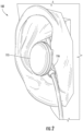
- the top cover 115 can be made using, for instance, a laser direct structuring process. As shown in FIG. 2 , when the wearable audio device 102 is worn in a user's ear, the ear engaging surface 116 is engaged with the ear.
- the top cover 115 can extend away from the ear and be exposed when the wearable audio device 102 is worn in the ear.
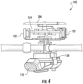
- FIGS. 4 and 5 depict interior components of a wearable audio device according to example embodiments of the present disclosure.
- Example components can include an audio source 150.
- the audio source 150 can be, for instance, a speaker drive.
- the speaker drive can convert electrical signals communicated via one or more conductors to the speaker drive to audio for output via speaker 155.
- the wearable audio device 102 can include one or more microphones 152.
- the microphone(s) 152 can be configured to record ambient noise observable near the wearable audio device.
- the ambient noise can be used, for instance, to provide noise cancelling capabilities for the wearable audio device 102.
- the wearable audio device 102 can include a printed circuit board 154 (e.g., a flexible printed circuit board).
- the printed circuit board 154 can include various circuit components (e.g., processors, memory, signal processing circuits, application specific integrated circuits, etc.) used to provide audio output from a source to a user.
- the wearable audio device 102 includes a touch panel 160.
- the touch panel 160 can be used to detect touch inputs from a user (e.g., the user touching the top cover 115 of the housing 114). Signals associated with the touch inputs can be communicated to the printed circuit board 154 to control various operating characteristics of the wearable audio device (e.g., volume, mute, channel, etc.).
- the wearable audio device 102 includes an antenna 200.
- the antenna 200 can be used to communicate wireless signals (e.g., RF signals) to and/or from the wearable audio device 102.
- a feed element 210 can communicate signals from the antenna 200 to and/or from the printed circuit board 154.
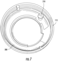
- FIG. 6 depicts a plan view of an example antenna 200 according to example embodiments of the present disclosure.
- the antenna 200 includes an arc-shaped conductor 204 (e.g., a trace).
- the arc-shaped conductor 204 includes a first end 206 and a second end 208 defining an opening 212.
- the arc-shaped conductor 204 can include a middle portion 220 between the first end 206 and the second end 208 (e.g., halfway between the first end 206 and the second end 208).
- a connecting portion 214 of the arc-shaped conductor 204 is located proximate the first end 206.
- the connecting portion 214 has a width that is greater than width associated with the remainder of the arc-shaped conductor 204.
- the connecting portion 214 can be configured to receive the feed element 210.
- the arc-shaped conductor 204 can have a length configured to accommodate communicating RF signals at a particular frequency.
- the arc-shaped conductor 204 can have a length equal to about a ⁇ /2 for a particular operating frequency where ⁇ is the wavelength associated with the particular frequency.
- the arc-shaped conductor 204 has a length configured to communicate signals at about 2.4 GHz.
- the antenna 200 can be located within the top cover 115 of the wearable audio device 102.
- the antenna 200 can extend around a peripheral portion of the circular top cover 115.
- the antenna 200 can be printed onto the circular top cover 115 (e.g., using a laser direct structuring process).
- the feed element 210 extends from the connecting portion 214 of the antenna 200.
- FIG. 8 depicts plots of electric field and current about the azimuth of the antenna 200. More particularly, curve 302 plots electric field as a function of azimuth about the antenna 200. As shown, the electric field is at a maximum at a location proximate first end 206 and second end 208 (e.g., proximate the opening 212) of the antenna 200. The electric field is at a minimum at or near the middle portion 220 of the antenna 200.
- Curve 304 plots current as a function of azimuth about the antenna 200. As shown, the current is at a maximum at a location proximate middle portion 220 of the antenna 200. The current is at a minimum at a location proximate the first end 206 and the second end 208 (e.g., proximate the opening 212) of the antenna 200.
- the antenna 200 is positioned and/or oriented within the wearable audio device 102 (e.g., within the top cover 115) such that when the wearable audio device 102 is worn in a user's ear, the portion of the antenna 200 associated with a maximum electric field is located further away from a user's ear relative to the portion of the antenna 200 associated with a minimum electric field. For instance, the portion of the antenna associated with a minimum current is located further away from a user's ear relative to the portion of the antenna 200 associated with a maximum current.
- FIG. 9 depicts one example positioning of an antenna relative to a user's ear according to example embodiments of the present disclosure.
- the antenna 200 can be positioned and/or oriented such that opening 212 defined by the first end 206 and the second end 208 is located further from the ear relative to middle portion 220 of the antenna 200. In this way, performance degradation of the antenna 200 resulting from the ear can be reduced.
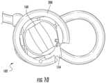
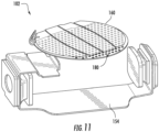
- FIGS. 10 , 11 and 12 depict the example implementation of a ground plane in a wearable audio device 102 according to example embodiments of the present disclosure.
- the wearable audio device 102 includes a touch panel 160 or a sensor.
- the touch panel 160 can include closely spaced planar metal sheets.
- the touch panel 160 is be arranged within an area A defined by an arc-shaped antenna.
- the touch panel 160 can be arranged within a top cover 115 with the antenna 200.
- the touch panel can be used to detect touch inputs from a user (e.g., the user touching the top cover 115 of the housing 114). Signals associated with the touch inputs can be communicated to the printed circuit board 154 to control various operating characteristics of the wearable audio device (e.g., volume, mute, channel, etc.).
- the touch panel 160 can be arranged over a printed circuit board 154 for the wearable audio device 102.
- the touch panel 160 can provide signals to the printed circuit board 154 via one or more conductors 165.
- a ground plane 180 can be disposed in spaced parallel relation with the touch panel 160.
- the ground plane 180 can be a conductive plane.
- the ground plane 180 can be meshed (e.g., slotted) to reduce capacitance between the touch panel 160 and the ground plane 180.
- the ground plane 180 can include an extension 185 that follows a path taken by conductor(s) 165 used to connect the touch sensor 160 to the printed circuit board 154.
- the extension 185 can be a solid conductive material.
- the extension 185 can connect the ground plane 180 to the printed circuit board 154.
- FIG. 13 depicts a wearable audio device 102 that includes RF chokes according to example embodiments of the present disclosure. More particularly, each conductor(s) 190 used to communicate power and/or signals to the wearable audio device 102 can include an RF choke 195. In some embodiments, the conductor(s) 190 can include the RF choke 195 at a location where the conductor is connected to the printed circuit board 154. The RF choke 195 can eliminate or reduce RF noise from a signal received and/or created by an antenna.
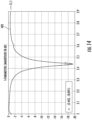
- FIG. 14 depicts example performance characteristics of an antenna for a wearable audio device according to example embodiments of the present disclosure.
- FIG. 14 plots S11 parameters (e.g. reflection coefficients ) (in dB) along the vertical axis and frequency along the horizontal axis. As shown by curve 402, the antenna exhibits good performance characteristics at its intended operating frequency (e.g., about 2.4 GHz).
- S11 parameters e.g. reflection coefficients
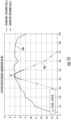
- FIG. 15 depicts example performance characteristics of an antenna for a wearable audio device according to example embodiments of the present disclosure.
- FIG. 15 plots antenna efficiency (in dB) along the vertical axis and frequency along the horizontal axis.
- Curve 404 represents radiation efficiency for the antenna.
- Curve 406 represents total efficiency for the antenna.
- the antenna demonstrates good efficiencies at its intended operating frequency (e.g., about 2.4 GHz).
Landscapes
- Physics & Mathematics (AREA)
- Engineering & Computer Science (AREA)
- Acoustics & Sound (AREA)
- Signal Processing (AREA)
- Support Of Aerials (AREA)
Claims (14)
- Dispositif audio portable (102) comprenant :un boîtier (114) définissant un intérieur et un extérieur, l'extérieur ayant une surface d'engagement de l'oreille (116) ; une source audio (150) étant contenue à l'intérieur du boîtier (114) ; etune antenne (200) située à l'intérieur du boîtier (114), l'antenne (200) comprenant un conducteur en forme d'arc (204) avec une première extrémité et une seconde extrémité (206, 208) avec une ouverture (212) définie entre la première extrémité et la seconde extrémité (206, 208),caractérisé parun panneau tactile (160) situé à l'intérieur d'une zone définie par le conducteur en forme d'arc (204).
- Dispositif audio portable selon la revendication 1, dans lequel la première extrémité et la seconde extrémité (206, 208) sont associées à un champ électrique maximal pour l'antenne (200) .
- Dispositif audio portable selon l'une quelconque des revendications précédentes, dans lequel une partie médiane (220) du conducteur en forme d'arc (204) est associée à un courant maximal pour l'antenne (200).
- Dispositif audio portable selon l'une quelconque des revendications précédentes, dans lequel le boîtier (114) comprend un couvercle supérieur (115), dans lequel l'antenne (200) est agencée à l'intérieur du couvercle supérieur (115).
- Dispositif audio portable selon l'une quelconque des revendications précédentes, dans lequel le dispositif audio portable (10) comprend un plan de masse (180) situé dans une relation parallèle espacée avec le panneau tactile (160).
- Dispositif audio portable selon la revendication 5, dans lequel au moins une partie du plan de masse (180) est maillée.
- Dispositif audio portable selon l'une quelconque des revendications précédentes, dans lequel le dispositif audio portable (10) comprend un élément d'alimentation (210) couplé à une partie de connexion (214) à proximité de la première extrémité (206) de l'antenne (200).
- Dispositif audio portable selon l'une quelconque des revendications précédentes, dans lequel le dispositif audio portable (10) comprend un ou plusieurs conducteurs (190) pour communiquer des signaux associés au dispositif audio portable (10) .
- Dispositif audio portable selon la revendication 8, dans lequel chacun des un ou plusieurs conducteurs (190) est couplé à une bobine d'arrêt de radiofréquence (RF) (195) au niveau d'un emplacement où le conducteur (190) connecté à une carte de circuit imprimé (154) situé à l'intérieur de ce boîtier (114).
- Dispositif audio portable selon la revendication 1, dans lequel le boîtier (114) comporte un couvercle supérieur (115) qui s'étend à partir d'une oreille lorsque le dispositif audio portable (10) est porté dans l'oreille, et l'antenne (200) est située à l'intérieur du couvercle supérieur (115).
- Dispositif audio portable selon la revendication 10, dans lequel l'antenne (200) est imprimée sur le couvercle supérieur (115) .
- Dispositif audio portable selon la revendication 10 ou 11, dans lequel le dispositif audio portable (10) comprend un plan de masse (180) situé à proximité du panneau tactile (160).
- Dispositif audio portable selon la revendication 1, comprenant en outre :un composant d'extension (185), le composant d'extension (185) comprenant un matériau conducteur solide et situé à l'intérieur de la zone définie par le conducteur en forme d'arc (204) ; etun plan de masse (180) situé dans une relation parallèle espacée avec le composant d'extension (185).
- Dispositif audio portable selon la revendication 13, dans lequel le boîtier (114) comprend un couvercle supérieur (115), l'antenne (200) et le composant d'extension (185) étant situés à l'intérieur du couvercle supérieur (115).
Applications Claiming Priority (2)
| Application Number | Priority Date | Filing Date | Title |
|---|---|---|---|
| US15/671,783 US10129635B1 (en) | 2017-08-08 | 2017-08-08 | Antenna for a wearable audio device |
| PCT/US2018/038554 WO2019032196A1 (fr) | 2017-08-08 | 2018-06-20 | Antenne pour dispositif audio portable |
Publications (2)
| Publication Number | Publication Date |
|---|---|
| EP3665743A1 EP3665743A1 (fr) | 2020-06-17 |
| EP3665743B1 true EP3665743B1 (fr) | 2024-08-07 |
Family
ID=62875341
Family Applications (1)
| Application Number | Title | Priority Date | Filing Date |
|---|---|---|---|
| EP18740043.7A Active EP3665743B1 (fr) | 2017-08-08 | 2018-06-20 | Antenne pour dispositif audio portable |
Country Status (5)
| Country | Link |
|---|---|
| US (1) | US10129635B1 (fr) |
| EP (1) | EP3665743B1 (fr) |
| CN (1) | CN110915065B (fr) |
| TW (1) | TWI699931B (fr) |
| WO (1) | WO2019032196A1 (fr) |
Families Citing this family (16)
| Publication number | Priority date | Publication date | Assignee | Title |
|---|---|---|---|---|
| USD872705S1 (en) * | 2017-09-15 | 2020-01-14 | Shengyuan Science and Technology (Shenzhen) Co., Ltd. | Earphone |
| KR102688841B1 (ko) * | 2020-02-10 | 2024-07-29 | 삼성전자 주식회사 | 이어 웨어러블 디바이스 |
| US11672078B2 (en) | 2020-06-15 | 2023-06-06 | Shure Acquisition Holdings, Inc. | Antenna application in wireless earphones |
| KR102696888B1 (ko) * | 2020-07-23 | 2024-08-20 | 삼성전자주식회사 | 터치 전극을 포함하는 전자 장치 |
| CN114257906B (zh) * | 2020-09-23 | 2023-07-04 | Oppo广东移动通信有限公司 | 无线耳机及整合触摸及天线结构的电子组件 |
| CN112135215B (zh) * | 2020-10-14 | 2025-09-05 | Oppo广东移动通信有限公司 | 音频设备以及无线耳机 |
| US11336975B1 (en) | 2021-02-01 | 2022-05-17 | Shure Acquisition Holdings, Inc. | Wearable device with detune-resilient antenna |
| EP4071929A1 (fr) * | 2021-04-06 | 2022-10-12 | Koninklijke Philips N.V. | Dispositif portable |
| CN113079435B (zh) * | 2021-04-07 | 2023-07-21 | 畅达星科技(深圳)有限公司 | 一种耳机 |
| WO2022227361A1 (fr) * | 2021-04-27 | 2022-11-03 | 深圳迈睿智能科技有限公司 | Antenne de détection de micro-ondes directionnelle à rétro-repliement de demi-onde |
| CN113616162B (zh) * | 2021-09-18 | 2024-04-05 | 中国人民解放军空军军医大学 | 一种提高睡眠监测准确性的可穿戴设备 |
| CN114624695B (zh) * | 2022-01-25 | 2024-10-15 | 深圳迈睿智能科技有限公司 | 微波探测方法和装置 |
| CN114390394B (zh) * | 2022-02-24 | 2025-06-13 | 听智慧(南京)科技有限公司 | 定制无线耳机 |
| EP4465653A4 (fr) * | 2022-04-11 | 2025-04-30 | Samsung Electronics Co., Ltd | Dispositif habitronique comprenant une antenne utilisant une grille de microphone |
| US12142821B2 (en) | 2022-12-21 | 2024-11-12 | Shure Acquisition Holdings, Inc. | Compact detune-resilient wireless device with touch-sensitive interface |
| US20240284084A1 (en) * | 2023-02-16 | 2024-08-22 | Bose Corporation | Extending antenna earth plane |
Citations (1)
| Publication number | Priority date | Publication date | Assignee | Title |
|---|---|---|---|---|
| US20170195466A1 (en) * | 2016-01-02 | 2017-07-06 | Erato (Cayman) Holdings Co., Ltd. | Radiofrequency communication device |
Family Cites Families (17)
| Publication number | Priority date | Publication date | Assignee | Title |
|---|---|---|---|---|
| US6671494B1 (en) * | 1998-06-18 | 2003-12-30 | Competive Technologies, Inc. | Small, battery operated RF transmitter for portable audio devices for use with headphones with RF receiver |
| JP2004128605A (ja) | 2002-09-30 | 2004-04-22 | Murata Mfg Co Ltd | アンテナ構造およびそれを備えた通信装置 |
| FR2863109B1 (fr) * | 2003-11-27 | 2006-05-19 | Centre Nat Rech Scient | Antenne a diagramme de rayonnement d'emission/reception configurable et orientable, station de base correspondante |
| JP4528735B2 (ja) | 2006-03-01 | 2010-08-18 | アルプス電気株式会社 | アンテナ装置およびそれを内蔵したヘッドホン |
| WO2008028136A2 (fr) * | 2006-09-01 | 2008-03-06 | Etymotic Research, Inc. | Antenne perfectionnée pour dispositifs sans fil miniatures et écouteurs sans fil améliorés portés intégralement par le canal auditif |
| JP4456588B2 (ja) | 2006-09-29 | 2010-04-28 | アルプス電気株式会社 | アンテナ構造及びヘッドセット |
| US7652628B2 (en) | 2008-03-13 | 2010-01-26 | Sony Ericsson Mobile Communications Ab | Antenna for use in earphone and earphone with integrated antenna |
| DK2628210T3 (en) * | 2010-10-12 | 2019-04-01 | Gn Hearing As | Hearing aid comprising an antenna device |
| CN105981219B (zh) * | 2014-08-29 | 2019-06-18 | 华为技术有限公司 | 一种天线和可穿戴设备 |
| KR20160052253A (ko) * | 2014-11-04 | 2016-05-12 | 삼성전자주식회사 | 안테나 장치 및 그것을 포함하는 전자 장치 |
| TWI583060B (zh) * | 2014-12-29 | 2017-05-11 | Merry Electronics Co Ltd | Coupling antenna |
| EP3110175B1 (fr) | 2015-06-24 | 2020-03-25 | Oticon A/s | Dispositif auditif comprenant une unité d'antenne encastrée dans tiroir de batterie |
| US10158339B2 (en) | 2015-12-11 | 2018-12-18 | Intel Corporation | Capacitive compensation structures using partially meshed ground planes |
| KR102485356B1 (ko) * | 2016-02-02 | 2023-01-06 | 삼성전자주식회사 | 사용자 인터페이싱 방법 및 이를 수행하는 전자 장치 |
| CN205946087U (zh) * | 2016-06-08 | 2017-02-08 | 佳邦科技股份有限公司 | 无线蓝牙耳机 |
| CN206195993U (zh) * | 2016-07-13 | 2017-05-24 | 珠海卓音科技有限公司 | 一种蓝牙耳机 |
| CN106060698B (zh) | 2016-07-26 | 2022-08-19 | 深圳市冠旭电子股份有限公司 | 触控式蓝牙耳机 |
-
2017
- 2017-08-08 US US15/671,783 patent/US10129635B1/en active Active
-
2018
- 2018-06-20 CN CN201880032272.6A patent/CN110915065B/zh not_active Expired - Fee Related
- 2018-06-20 EP EP18740043.7A patent/EP3665743B1/fr active Active
- 2018-06-20 WO PCT/US2018/038554 patent/WO2019032196A1/fr not_active Ceased
- 2018-06-25 TW TW107121721A patent/TWI699931B/zh active
Patent Citations (1)
| Publication number | Priority date | Publication date | Assignee | Title |
|---|---|---|---|---|
| US20170195466A1 (en) * | 2016-01-02 | 2017-07-06 | Erato (Cayman) Holdings Co., Ltd. | Radiofrequency communication device |
Also Published As
| Publication number | Publication date |
|---|---|
| CN110915065B (zh) | 2022-01-28 |
| CN110915065A (zh) | 2020-03-24 |
| TWI699931B (zh) | 2020-07-21 |
| US10129635B1 (en) | 2018-11-13 |
| TW201911651A (zh) | 2019-03-16 |
| WO2019032196A1 (fr) | 2019-02-14 |
| EP3665743A1 (fr) | 2020-06-17 |
Similar Documents
| Publication | Publication Date | Title |
|---|---|---|
| EP3665743B1 (fr) | Antenne pour dispositif audio portable | |
| US12284489B2 (en) | RF antenna and hearing device with RF antenna | |
| EP3531718B1 (fr) | Dispositif d'aide auditive doté d'une antenne | |
| AU2016102106B4 (en) | Antennas for wireless earbuds | |
| US10237657B2 (en) | Wireless headset antennas | |
| JP6396327B2 (ja) | 携帯用端末機のアンテナ装置 | |
| US9466876B2 (en) | Antenna | |
| US8669905B2 (en) | Portable communication device comprising an antenna | |
| KR101335824B1 (ko) | 이동단말기 | |
| US9462396B2 (en) | Hearing assistance coplanar waveguide | |
| US8477069B2 (en) | Portable electronic device and antenna thereof | |
| CN107645053B (zh) | 天线结构及具有该天线结构的无线通信装置 | |
| CN105024136A (zh) | 移动终端 | |
| US8593351B2 (en) | Portable electronic device | |
| JP6184778B2 (ja) | アンテナエレメントおよびアンテナ装置 | |
| CN116417782B (zh) | 一种无线耳机及终端天线 | |
| WO2020011698A1 (fr) | Dispositif d'écouteurs avec arrangement d'antenne | |
| JP2007251367A (ja) | ヘッドセット装置 | |
| DK179697B1 (en) | Hearing aid with antenna on printed circuit board |
Legal Events
| Date | Code | Title | Description |
|---|---|---|---|
| STAA | Information on the status of an ep patent application or granted ep patent |
Free format text: STATUS: UNKNOWN |
|
| STAA | Information on the status of an ep patent application or granted ep patent |
Free format text: STATUS: THE INTERNATIONAL PUBLICATION HAS BEEN MADE |
|
| PUAI | Public reference made under article 153(3) epc to a published international application that has entered the european phase |
Free format text: ORIGINAL CODE: 0009012 |
|
| STAA | Information on the status of an ep patent application or granted ep patent |
Free format text: STATUS: REQUEST FOR EXAMINATION WAS MADE |
|
| 17P | Request for examination filed |
Effective date: 20191106 |
|
| AK | Designated contracting states |
Kind code of ref document: A1 Designated state(s): AL AT BE BG CH CY CZ DE DK EE ES FI FR GB GR HR HU IE IS IT LI LT LU LV MC MK MT NL NO PL PT RO RS SE SI SK SM TR |
|
| AX | Request for extension of the european patent |
Extension state: BA ME |
|
| DAV | Request for validation of the european patent (deleted) | ||
| DAX | Request for extension of the european patent (deleted) | ||
| STAA | Information on the status of an ep patent application or granted ep patent |
Free format text: STATUS: EXAMINATION IS IN PROGRESS |
|
| 17Q | First examination report despatched |
Effective date: 20211110 |
|
| GRAP | Despatch of communication of intention to grant a patent |
Free format text: ORIGINAL CODE: EPIDOSNIGR1 |
|
| STAA | Information on the status of an ep patent application or granted ep patent |
Free format text: STATUS: GRANT OF PATENT IS INTENDED |
|
| INTG | Intention to grant announced |
Effective date: 20240215 |
|
| GRAS | Grant fee paid |
Free format text: ORIGINAL CODE: EPIDOSNIGR3 |
|
| GRAA | (expected) grant |
Free format text: ORIGINAL CODE: 0009210 |
|
| STAA | Information on the status of an ep patent application or granted ep patent |
Free format text: STATUS: THE PATENT HAS BEEN GRANTED |
|
| P01 | Opt-out of the competence of the unified patent court (upc) registered |
Free format text: CASE NUMBER: APP_35479/2024 Effective date: 20240613 |
|
| AK | Designated contracting states |
Kind code of ref document: B1 Designated state(s): AL AT BE BG CH CY CZ DE DK EE ES FI FR GB GR HR HU IE IS IT LI LT LU LV MC MK MT NL NO PL PT RO RS SE SI SK SM TR |
|
| REG | Reference to a national code |
Ref country code: GB Ref legal event code: FG4D |
|
| REG | Reference to a national code |
Ref country code: CH Ref legal event code: EP |
|
| REG | Reference to a national code |
Ref country code: DE Ref legal event code: R096 Ref document number: 602018072756 Country of ref document: DE |
|
| REG | Reference to a national code |
Ref country code: IE Ref legal event code: FG4D |
|
| REG | Reference to a national code |
Ref country code: NL Ref legal event code: FP |
|
| REG | Reference to a national code |
Ref country code: LT Ref legal event code: MG9D |
|
| PG25 | Lapsed in a contracting state [announced via postgrant information from national office to epo] |
Ref country code: NO Free format text: LAPSE BECAUSE OF FAILURE TO SUBMIT A TRANSLATION OF THE DESCRIPTION OR TO PAY THE FEE WITHIN THE PRESCRIBED TIME-LIMIT Effective date: 20241107 |
|
| REG | Reference to a national code |
Ref country code: AT Ref legal event code: MK05 Ref document number: 1711981 Country of ref document: AT Kind code of ref document: T Effective date: 20240807 |
|
| PG25 | Lapsed in a contracting state [announced via postgrant information from national office to epo] |
Ref country code: FI Free format text: LAPSE BECAUSE OF FAILURE TO SUBMIT A TRANSLATION OF THE DESCRIPTION OR TO PAY THE FEE WITHIN THE PRESCRIBED TIME-LIMIT Effective date: 20240807 Ref country code: GR Free format text: LAPSE BECAUSE OF FAILURE TO SUBMIT A TRANSLATION OF THE DESCRIPTION OR TO PAY THE FEE WITHIN THE PRESCRIBED TIME-LIMIT Effective date: 20241108 Ref country code: PT Free format text: LAPSE BECAUSE OF FAILURE TO SUBMIT A TRANSLATION OF THE DESCRIPTION OR TO PAY THE FEE WITHIN THE PRESCRIBED TIME-LIMIT Effective date: 20241209 Ref country code: PL Free format text: LAPSE BECAUSE OF FAILURE TO SUBMIT A TRANSLATION OF THE DESCRIPTION OR TO PAY THE FEE WITHIN THE PRESCRIBED TIME-LIMIT Effective date: 20240807 |
|
| PG25 | Lapsed in a contracting state [announced via postgrant information from national office to epo] |
Ref country code: BG Free format text: LAPSE BECAUSE OF FAILURE TO SUBMIT A TRANSLATION OF THE DESCRIPTION OR TO PAY THE FEE WITHIN THE PRESCRIBED TIME-LIMIT Effective date: 20240807 |
|
| PG25 | Lapsed in a contracting state [announced via postgrant information from national office to epo] |
Ref country code: LV Free format text: LAPSE BECAUSE OF FAILURE TO SUBMIT A TRANSLATION OF THE DESCRIPTION OR TO PAY THE FEE WITHIN THE PRESCRIBED TIME-LIMIT Effective date: 20240807 |
|
| PG25 | Lapsed in a contracting state [announced via postgrant information from national office to epo] |
Ref country code: AT Free format text: LAPSE BECAUSE OF FAILURE TO SUBMIT A TRANSLATION OF THE DESCRIPTION OR TO PAY THE FEE WITHIN THE PRESCRIBED TIME-LIMIT Effective date: 20240807 Ref country code: IS Free format text: LAPSE BECAUSE OF FAILURE TO SUBMIT A TRANSLATION OF THE DESCRIPTION OR TO PAY THE FEE WITHIN THE PRESCRIBED TIME-LIMIT Effective date: 20241207 |
|
| PG25 | Lapsed in a contracting state [announced via postgrant information from national office to epo] |
Ref country code: HR Free format text: LAPSE BECAUSE OF FAILURE TO SUBMIT A TRANSLATION OF THE DESCRIPTION OR TO PAY THE FEE WITHIN THE PRESCRIBED TIME-LIMIT Effective date: 20240807 |
|
| PG25 | Lapsed in a contracting state [announced via postgrant information from national office to epo] |
Ref country code: ES Free format text: LAPSE BECAUSE OF FAILURE TO SUBMIT A TRANSLATION OF THE DESCRIPTION OR TO PAY THE FEE WITHIN THE PRESCRIBED TIME-LIMIT Effective date: 20240807 Ref country code: RS Free format text: LAPSE BECAUSE OF FAILURE TO SUBMIT A TRANSLATION OF THE DESCRIPTION OR TO PAY THE FEE WITHIN THE PRESCRIBED TIME-LIMIT Effective date: 20241107 |
|
| PG25 | Lapsed in a contracting state [announced via postgrant information from national office to epo] |
Ref country code: RS Free format text: LAPSE BECAUSE OF FAILURE TO SUBMIT A TRANSLATION OF THE DESCRIPTION OR TO PAY THE FEE WITHIN THE PRESCRIBED TIME-LIMIT Effective date: 20241107 Ref country code: PT Free format text: LAPSE BECAUSE OF FAILURE TO SUBMIT A TRANSLATION OF THE DESCRIPTION OR TO PAY THE FEE WITHIN THE PRESCRIBED TIME-LIMIT Effective date: 20241209 Ref country code: PL Free format text: LAPSE BECAUSE OF FAILURE TO SUBMIT A TRANSLATION OF THE DESCRIPTION OR TO PAY THE FEE WITHIN THE PRESCRIBED TIME-LIMIT Effective date: 20240807 Ref country code: NO Free format text: LAPSE BECAUSE OF FAILURE TO SUBMIT A TRANSLATION OF THE DESCRIPTION OR TO PAY THE FEE WITHIN THE PRESCRIBED TIME-LIMIT Effective date: 20241107 Ref country code: LV Free format text: LAPSE BECAUSE OF FAILURE TO SUBMIT A TRANSLATION OF THE DESCRIPTION OR TO PAY THE FEE WITHIN THE PRESCRIBED TIME-LIMIT Effective date: 20240807 Ref country code: IS Free format text: LAPSE BECAUSE OF FAILURE TO SUBMIT A TRANSLATION OF THE DESCRIPTION OR TO PAY THE FEE WITHIN THE PRESCRIBED TIME-LIMIT Effective date: 20241207 Ref country code: HR Free format text: LAPSE BECAUSE OF FAILURE TO SUBMIT A TRANSLATION OF THE DESCRIPTION OR TO PAY THE FEE WITHIN THE PRESCRIBED TIME-LIMIT Effective date: 20240807 Ref country code: GR Free format text: LAPSE BECAUSE OF FAILURE TO SUBMIT A TRANSLATION OF THE DESCRIPTION OR TO PAY THE FEE WITHIN THE PRESCRIBED TIME-LIMIT Effective date: 20241108 Ref country code: FI Free format text: LAPSE BECAUSE OF FAILURE TO SUBMIT A TRANSLATION OF THE DESCRIPTION OR TO PAY THE FEE WITHIN THE PRESCRIBED TIME-LIMIT Effective date: 20240807 Ref country code: ES Free format text: LAPSE BECAUSE OF FAILURE TO SUBMIT A TRANSLATION OF THE DESCRIPTION OR TO PAY THE FEE WITHIN THE PRESCRIBED TIME-LIMIT Effective date: 20240807 Ref country code: BG Free format text: LAPSE BECAUSE OF FAILURE TO SUBMIT A TRANSLATION OF THE DESCRIPTION OR TO PAY THE FEE WITHIN THE PRESCRIBED TIME-LIMIT Effective date: 20240807 Ref country code: AT Free format text: LAPSE BECAUSE OF FAILURE TO SUBMIT A TRANSLATION OF THE DESCRIPTION OR TO PAY THE FEE WITHIN THE PRESCRIBED TIME-LIMIT Effective date: 20240807 |
|
| PG25 | Lapsed in a contracting state [announced via postgrant information from national office to epo] |
Ref country code: RO Free format text: LAPSE BECAUSE OF FAILURE TO SUBMIT A TRANSLATION OF THE DESCRIPTION OR TO PAY THE FEE WITHIN THE PRESCRIBED TIME-LIMIT Effective date: 20240807 Ref country code: SM Free format text: LAPSE BECAUSE OF FAILURE TO SUBMIT A TRANSLATION OF THE DESCRIPTION OR TO PAY THE FEE WITHIN THE PRESCRIBED TIME-LIMIT Effective date: 20240807 Ref country code: DK Free format text: LAPSE BECAUSE OF FAILURE TO SUBMIT A TRANSLATION OF THE DESCRIPTION OR TO PAY THE FEE WITHIN THE PRESCRIBED TIME-LIMIT Effective date: 20240807 |
|
| PG25 | Lapsed in a contracting state [announced via postgrant information from national office to epo] |
Ref country code: EE Free format text: LAPSE BECAUSE OF FAILURE TO SUBMIT A TRANSLATION OF THE DESCRIPTION OR TO PAY THE FEE WITHIN THE PRESCRIBED TIME-LIMIT Effective date: 20240807 |
|
| PG25 | Lapsed in a contracting state [announced via postgrant information from national office to epo] |
Ref country code: CZ Free format text: LAPSE BECAUSE OF FAILURE TO SUBMIT A TRANSLATION OF THE DESCRIPTION OR TO PAY THE FEE WITHIN THE PRESCRIBED TIME-LIMIT Effective date: 20240807 |
|
| PG25 | Lapsed in a contracting state [announced via postgrant information from national office to epo] |
Ref country code: SK Free format text: LAPSE BECAUSE OF FAILURE TO SUBMIT A TRANSLATION OF THE DESCRIPTION OR TO PAY THE FEE WITHIN THE PRESCRIBED TIME-LIMIT Effective date: 20240807 |
|
| REG | Reference to a national code |
Ref country code: DE Ref legal event code: R097 Ref document number: 602018072756 Country of ref document: DE |
|
| PLBE | No opposition filed within time limit |
Free format text: ORIGINAL CODE: 0009261 |
|
| STAA | Information on the status of an ep patent application or granted ep patent |
Free format text: STATUS: NO OPPOSITION FILED WITHIN TIME LIMIT |
|
| PGFP | Annual fee paid to national office [announced via postgrant information from national office to epo] |
Ref country code: DE Payment date: 20250627 Year of fee payment: 8 |
|
| PGFP | Annual fee paid to national office [announced via postgrant information from national office to epo] |
Ref country code: GB Payment date: 20250627 Year of fee payment: 8 |
|
| PGFP | Annual fee paid to national office [announced via postgrant information from national office to epo] |
Ref country code: NL Payment date: 20250626 Year of fee payment: 8 |
|
| 26N | No opposition filed |
Effective date: 20250508 |
|
| PGFP | Annual fee paid to national office [announced via postgrant information from national office to epo] |
Ref country code: FR Payment date: 20250625 Year of fee payment: 8 |
|
| PG25 | Lapsed in a contracting state [announced via postgrant information from national office to epo] |
Ref country code: SE Free format text: LAPSE BECAUSE OF FAILURE TO SUBMIT A TRANSLATION OF THE DESCRIPTION OR TO PAY THE FEE WITHIN THE PRESCRIBED TIME-LIMIT Effective date: 20240807 |
|
| REG | Reference to a national code |
Ref country code: CH Ref legal event code: H13 Free format text: ST27 STATUS EVENT CODE: U-0-0-H10-H13 (AS PROVIDED BY THE NATIONAL OFFICE) Effective date: 20260127 |
|
| PG25 | Lapsed in a contracting state [announced via postgrant information from national office to epo] |
Ref country code: IT Free format text: LAPSE BECAUSE OF FAILURE TO SUBMIT A TRANSLATION OF THE DESCRIPTION OR TO PAY THE FEE WITHIN THE PRESCRIBED TIME-LIMIT Effective date: 20240807 |
|
| PG25 | Lapsed in a contracting state [announced via postgrant information from national office to epo] |
Ref country code: MC Free format text: LAPSE BECAUSE OF FAILURE TO SUBMIT A TRANSLATION OF THE DESCRIPTION OR TO PAY THE FEE WITHIN THE PRESCRIBED TIME-LIMIT Effective date: 20240807 |
|
| PG25 | Lapsed in a contracting state [announced via postgrant information from national office to epo] |
Ref country code: LU Free format text: LAPSE BECAUSE OF NON-PAYMENT OF DUE FEES Effective date: 20250620 |
|
| REG | Reference to a national code |
Ref country code: BE Ref legal event code: MM Effective date: 20250630 |
|
| PG25 | Lapsed in a contracting state [announced via postgrant information from national office to epo] |
Ref country code: IE Free format text: LAPSE BECAUSE OF NON-PAYMENT OF DUE FEES Effective date: 20250620 |
|
| PG25 | Lapsed in a contracting state [announced via postgrant information from national office to epo] |
Ref country code: BE Free format text: LAPSE BECAUSE OF NON-PAYMENT OF DUE FEES Effective date: 20250630 |
|
| PG25 | Lapsed in a contracting state [announced via postgrant information from national office to epo] |
Ref country code: CH Free format text: LAPSE BECAUSE OF NON-PAYMENT OF DUE FEES Effective date: 20250630 |