EP3665854B1 - Transmission de liaison descendante en tdd prenant en charge des fenb-ido - Google Patents
Transmission de liaison descendante en tdd prenant en charge des fenb-ido Download PDFInfo
- Publication number
- EP3665854B1 EP3665854B1 EP18844017.6A EP18844017A EP3665854B1 EP 3665854 B1 EP3665854 B1 EP 3665854B1 EP 18844017 A EP18844017 A EP 18844017A EP 3665854 B1 EP3665854 B1 EP 3665854B1
- Authority
- EP
- European Patent Office
- Prior art keywords
- sib1
- subframes
- subframe
- downlink
- iot
- Prior art date
- Legal status (The legal status is an assumption and is not a legal conclusion. Google has not performed a legal analysis and makes no representation as to the accuracy of the status listed.)
- Active
Links
Images







Classifications
-
- H—ELECTRICITY
- H04—ELECTRIC COMMUNICATION TECHNIQUE
- H04W—WIRELESS COMMUNICATION NETWORKS
- H04W72/00—Local resource management
- H04W72/12—Wireless traffic scheduling
- H04W72/1263—Mapping of traffic onto schedule, e.g. scheduled allocation or multiplexing of flows
- H04W72/1273—Mapping of traffic onto schedule, e.g. scheduled allocation or multiplexing of flows of downlink data flows
-
- H—ELECTRICITY
- H04—ELECTRIC COMMUNICATION TECHNIQUE
- H04L—TRANSMISSION OF DIGITAL INFORMATION, e.g. TELEGRAPHIC COMMUNICATION
- H04L5/00—Arrangements affording multiple use of the transmission path
- H04L5/0001—Arrangements for dividing the transmission path
- H04L5/0028—Variable division
-
- H—ELECTRICITY
- H04—ELECTRIC COMMUNICATION TECHNIQUE
- H04J—MULTIPLEX COMMUNICATION
- H04J11/00—Orthogonal multiplex systems, e.g. using WALSH codes
- H04J11/0069—Cell search, i.e. determining cell identity [cell-ID]
-
- H—ELECTRICITY
- H04—ELECTRIC COMMUNICATION TECHNIQUE
- H04L—TRANSMISSION OF DIGITAL INFORMATION, e.g. TELEGRAPHIC COMMUNICATION
- H04L1/00—Arrangements for detecting or preventing errors in the information received
- H04L1/0001—Systems modifying transmission characteristics according to link quality, e.g. power backoff
- H04L1/0009—Systems modifying transmission characteristics according to link quality, e.g. power backoff by adapting the channel coding
- H04L1/0011—Systems modifying transmission characteristics according to link quality, e.g. power backoff by adapting the channel coding applied to payload information
-
- H—ELECTRICITY
- H04—ELECTRIC COMMUNICATION TECHNIQUE
- H04L—TRANSMISSION OF DIGITAL INFORMATION, e.g. TELEGRAPHIC COMMUNICATION
- H04L1/00—Arrangements for detecting or preventing errors in the information received
- H04L1/004—Arrangements for detecting or preventing errors in the information received by using forward error control
- H04L1/0075—Transmission of coding parameters to receiver
-
- H—ELECTRICITY
- H04—ELECTRIC COMMUNICATION TECHNIQUE
- H04L—TRANSMISSION OF DIGITAL INFORMATION, e.g. TELEGRAPHIC COMMUNICATION
- H04L1/00—Arrangements for detecting or preventing errors in the information received
- H04L1/08—Arrangements for detecting or preventing errors in the information received by repeating transmission, e.g. Verdan system
-
- H—ELECTRICITY
- H04—ELECTRIC COMMUNICATION TECHNIQUE
- H04L—TRANSMISSION OF DIGITAL INFORMATION, e.g. TELEGRAPHIC COMMUNICATION
- H04L1/00—Arrangements for detecting or preventing errors in the information received
- H04L1/12—Arrangements for detecting or preventing errors in the information received by using return channel
- H04L1/16—Arrangements for detecting or preventing errors in the information received by using return channel in which the return channel carries supervisory signals, e.g. repetition request signals
- H04L1/18—Automatic repetition systems, e.g. Van Duuren systems
-
- H—ELECTRICITY
- H04—ELECTRIC COMMUNICATION TECHNIQUE
- H04L—TRANSMISSION OF DIGITAL INFORMATION, e.g. TELEGRAPHIC COMMUNICATION
- H04L1/00—Arrangements for detecting or preventing errors in the information received
- H04L1/12—Arrangements for detecting or preventing errors in the information received by using return channel
- H04L1/16—Arrangements for detecting or preventing errors in the information received by using return channel in which the return channel carries supervisory signals, e.g. repetition request signals
- H04L1/18—Automatic repetition systems, e.g. Van Duuren systems
- H04L1/1867—Arrangements specially adapted for the transmitter end
- H04L1/1887—Scheduling and prioritising arrangements
-
- H—ELECTRICITY
- H04—ELECTRIC COMMUNICATION TECHNIQUE
- H04L—TRANSMISSION OF DIGITAL INFORMATION, e.g. TELEGRAPHIC COMMUNICATION
- H04L27/00—Modulated-carrier systems
- H04L27/26—Systems using multi-frequency codes
- H04L27/2601—Multicarrier modulation systems
- H04L27/2647—Arrangements specific to the receiver only
- H04L27/2655—Synchronisation arrangements
- H04L27/2657—Carrier synchronisation
-
- H—ELECTRICITY
- H04—ELECTRIC COMMUNICATION TECHNIQUE
- H04L—TRANSMISSION OF DIGITAL INFORMATION, e.g. TELEGRAPHIC COMMUNICATION
- H04L5/00—Arrangements affording multiple use of the transmission path
- H04L5/003—Arrangements for allocating sub-channels of the transmission path
- H04L5/0048—Allocation of pilot signals, i.e. of signals known to the receiver
-
- H—ELECTRICITY
- H04—ELECTRIC COMMUNICATION TECHNIQUE
- H04L—TRANSMISSION OF DIGITAL INFORMATION, e.g. TELEGRAPHIC COMMUNICATION
- H04L5/00—Arrangements affording multiple use of the transmission path
- H04L5/003—Arrangements for allocating sub-channels of the transmission path
- H04L5/0053—Allocation of signalling, i.e. of overhead other than pilot signals
-
- H—ELECTRICITY
- H04—ELECTRIC COMMUNICATION TECHNIQUE
- H04L—TRANSMISSION OF DIGITAL INFORMATION, e.g. TELEGRAPHIC COMMUNICATION
- H04L5/00—Arrangements affording multiple use of the transmission path
- H04L5/0091—Signalling for the administration of the divided path, e.g. signalling of configuration information
- H04L5/0094—Indication of how sub-channels of the path are allocated
-
- H—ELECTRICITY
- H04—ELECTRIC COMMUNICATION TECHNIQUE
- H04L—TRANSMISSION OF DIGITAL INFORMATION, e.g. TELEGRAPHIC COMMUNICATION
- H04L5/00—Arrangements affording multiple use of the transmission path
- H04L5/14—Two-way operation using the same type of signal, i.e. duplex
- H04L5/143—Two-way operation using the same type of signal, i.e. duplex for modulated signals
-
- H—ELECTRICITY
- H04—ELECTRIC COMMUNICATION TECHNIQUE
- H04L—TRANSMISSION OF DIGITAL INFORMATION, e.g. TELEGRAPHIC COMMUNICATION
- H04L5/00—Arrangements affording multiple use of the transmission path
- H04L5/14—Two-way operation using the same type of signal, i.e. duplex
- H04L5/1469—Two-way operation using the same type of signal, i.e. duplex using time-sharing
-
- H—ELECTRICITY
- H04—ELECTRIC COMMUNICATION TECHNIQUE
- H04W—WIRELESS COMMUNICATION NETWORKS
- H04W72/00—Local resource management
- H04W72/04—Wireless resource allocation
- H04W72/044—Wireless resource allocation based on the type of the allocated resource
- H04W72/0446—Resources in time domain, e.g. slots or frames
-
- H—ELECTRICITY
- H04—ELECTRIC COMMUNICATION TECHNIQUE
- H04W—WIRELESS COMMUNICATION NETWORKS
- H04W72/00—Local resource management
- H04W72/20—Control channels or signalling for resource management
- H04W72/23—Control channels or signalling for resource management in the downlink direction of a wireless link, i.e. towards a terminal
-
- H—ELECTRICITY
- H04—ELECTRIC COMMUNICATION TECHNIQUE
- H04W—WIRELESS COMMUNICATION NETWORKS
- H04W56/00—Synchronisation arrangements
Definitions
- Embodiments pertain to wireless communications. Some embodiments relate to wireless networks including 3GPP (Third Generation Partnership Project) networks, 3GPP LTE (Long Term Evolution) networks, and 3GPP LTE-A (LTE Advanced) networks. Some embodiments relate to Fifth Generation (5G) networks. Some embodiments relate to New Radio (NR) networks. Some embodiments relate to further enhanced internet-of-things (feNB-IoT) techniques. Some embodiments relate to internet-of-things (IoT) techniques. The scope of protection is solely defined by the appended independent claims. Further embodiments are defined by the dependent claims.
- TDD time-division duplexing
- Such systems may be useful in various scenarios. For instance, when a block of spectrum is available, but blocks of paired spectrum are not available, a TDD arrangement may be a good option.
- different configurations of uplink subframes and downlink subframes within a radio frame may be possible. Allocation of resources and/or scheduling of transmissions for such configurations may be challenging. Accordingly, there is a general need for methods and systems to enable TDD operation in these and other scenarios.
- FIG. 1A is a functional diagram of an example network in accordance with some embodiments.
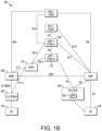
- FIG. 1B is a functional diagram of another example network in accordance with some embodiments.
- the network 100 may be a Third Generation Partnership Project (3GPP) network.
- the network 150 may be a 3GPP network.
- the network 150 may be a new radio (NR) network. It should be noted that embodiments are not limited to usage of 3GPP networks, however, as other networks may be used in some embodiments.
- a Fifth Generation (5G) network may be used in some cases.
- a New Radio (NR) network may be used in some cases.
- a wireless local area network (WLAN) may be used in some cases.
- a network may include one or more components shown in FIG. 1A . Some embodiments may not necessarily include all components shown in FIG. 1A , and some embodiments may include additional components not shown in FIG. 1A .
- a network may include one or more components shown in FIG. 1B . Some embodiments may not necessarily include all components shown in FIG. 1B , and some embodiments may include additional components not shown in FIG. 1B .
- a network may include one or more components shown in FIG. 1A and one or more components shown in FIG. 1B . In some embodiments, a network may include one or more components shown in FIG. 1A , one or more components shown in FIG. 1B and one or more additional components.
- the network 100 may comprise a radio access network (RAN) 101 and the core network 120 (e.g., shown as an evolved packet core (EPC)) coupled together through an S1 interface 115.
- RAN radio access network
- EPC evolved packet core
- the RAN 101 may be an evolved universal terrestrial radio access network (E-UTRAN).
- E-UTRAN evolved universal terrestrial radio access network
- the RAN 101 may include one or more components of a New Radio (NR) network.
- NR New Radio
- the RAN 101 may include one or more components of an E-UTRAN and one or more components of another network (including but not limited to an NR network).
- the core network 120 may include a mobility management entity (MME) 122, a serving gateway (serving GW) 124, and packet data network gateway (PDN GW) 126.
- MME mobility management entity
- serving GW serving gateway
- PDN GW packet data network gateway
- the network 100 may include (and/or support) one or more Evolved Node-B's (eNBs) 104 (which may operate as base stations) for communicating with User Equipment (UE) 102.
- the eNBs 104 may include macro eNBs and low power (LP) eNBs, in some embodiments.
- the network 100 may include (and/or support) one or more Generation Node-B's (gNBs) 105.
- gNBs Generation Node-B's
- one or more eNBs 104 may be configured to operate as gNBs 105. Embodiments are not limited to the number of eNBs 104 shown in FIG. 1A or to the number of gNBs 105 shown in FIG. 1A .
- the network 100 may not necessarily include eNBs 104. Embodiments are also not limited to the connectivity of components shown in FIG. 1A .
- references herein to an eNB 104 or to a gNB 105 are not limiting.
- one or more operations, methods and/or techniques may be practiced by a base station component (and/or other component), including but not limited to a gNB 105, an eNB 104, a serving cell, a transmit receive point (TRP) and/or other.
- the base station component may be configured to operate in accordance with a New Radio (NR) protocol and/or NR standard, although the scope of embodiments is not limited in this respect.
- the base station component may be configured to operate in accordance with a Fifth Generation (5G) protocol and/or 5G standard, although the scope of embodiments is not limited in this respect.
- 5G Fifth Generation
- one or more of the UEs 102 and/or eNBs 104 may be configured to operate in accordance with an NR protocol and/or NR techniques.
- References to a UE 102, eNB 104 and/or gNB 105 as part of descriptions herein are not limiting.
- descriptions of one or more operations, techniques and/or methods practiced by a gNB 105 are not limiting.
- one or more of those operations, techniques and/or methods may be practiced by an eNB 104 and/or other base station component.
- one or more of the UEs 102, eNBs 104 and/or gNBs 105 may be configured to operate in accordance with technique(s), protocol(s) and/or standard(s) related to one or more of: internet-of-things (IoT), narrowband IoT (NB IoT), enhanced NB IoT (eNB-IoT), further enchanced narrowband IoT (feNB-IoT) and/or other.
- IoT internet-of-things
- NB IoT narrowband IoT
- eNB-IoT enhanced NB IoT
- feNB-IoT further enchanced narrowband IoT
- the UE 102 may transmit signals (data, control and/or other) to the gNB 105, and may receive signals (data, control and/or other) from the gNB 105. In some embodiments, the UE 102 may transmit signals (data, control and/or other) to the eNB 104, and may receive signals (data, control and/or other) from the eNB 104. These embodiments will be described in more detail below.
- the MME 122 is similar in function to the control plane of legacy Serving GPRS Support Nodes (SGSN).
- the MME 122 manages mobility aspects in access such as gateway selection and tracking area list management.
- the serving GW 124 terminates the interface toward the RAN 101, and routes data packets between the RAN 101 and the core network 120. In addition, it may be a local mobility anchor point for inter-eNB handovers and also may provide an anchor for inter-3GPP mobility. Other responsibilities may include lawful intercept, charging, and some policy enforcement.
- the serving GW 124 and the MME 122 may be implemented in one physical node or separate physical nodes.
- the PDN GW 126 terminates an SGi interface toward the packet data network (PDN).
- PDN packet data network
- the PDN GW 126 routes data packets between the EPC 120 and the external PDN, and may be a key node for policy enforcement and charging data collection. It may also provide an anchor point for mobility with non-LTE accesses.
- the external PDN can be any kind of IP network, as well as an IP Multimedia Subsystem (IMS) domain.
- IMS IP Multimedia Subsystem
- the PDN GW 126 and the serving GW 124 may be implemented in one physical node or separated physical nodes.
- the eNBs 104 terminate the air interface protocol and may be the first point of contact for a UE 102.
- an eNB 104 may fulfill various logical functions for the network 100, including but not limited to RNC (radio network controller functions) such as radio bearer management, uplink and downlink dynamic radio resource management and data packet scheduling, and mobility management.
- RNC radio network controller functions
- UEs 102 may be configured to communicate Orthogonal Frequency Division Multiplexing (OFDM) communication signals with an eNB 104 and/or gNB 105 over a multicarrier communication channel in accordance with an Orthogonal Frequency Division Multiple Access (OFDMA) communication technique.
- OFDM Orthogonal Frequency Division Multiplexing
- eNBs 104 and/or gNBs 105 may be configured to communicate OFDM communication signals with a UE 102 over a multicarrier communication channel in accordance with an OFDMA communication technique.
- the OFDM signals may comprise a plurality of orthogonal subcarriers.
- the S1 interface 115 is the interface that separates the RAN 101 and the EPC 120. It may be split into two parts: the S1-U, which carries traffic data between the eNBs 104 and the serving GW 124, and the S1-MME, which is a signaling interface between the eNBs 104 and the MME 122.
- the X2 interface is the interface between eNBs 104.
- the X2 interface comprises two parts, the X2-C and X2-U.
- the X2-C is the control plane interface between the eNBs 104
- the X2-U is the user plane interface between the eNBs 104.
- the S1 interface 115 (and/or similar interface) may be split into two parts: the S1-U, which carries traffic data between the gNBs 105 and the serving GW 124, and the S1-MME, which is a signaling interface between the gNBs 104 and the MME 122.
- the X2 interface (and/or similar interface) may enable communication between eNBs 104, communication between gNBs 105 and/or communication between an eNB 104 and a gNB 105.
- LP cells are typically used to extend coverage to indoor areas where outdoor signals do not reach well, or to add network capacity in areas with very dense phone usage, such as train stations.
- the term low power (LP) eNB refers to any suitable relatively low power eNB for implementing a narrower cell (narrower than a macro cell) such as a femtocell, a picocell, or a micro cell.
- Femtocell eNBs are typically provided by a mobile network operator to its residential or enterprise customers.
- a femtocell is typically the size of a residential gateway or smaller and generally connects to the user's broadband line.
- a picocell is a wireless communication system typically covering a small area, such as in-building (offices, shopping malls, train stations, etc.), or more recently in-aircraft.
- a picocell eNB can generally connect through the X2 link to another eNB such as a macro eNB through its base station controller (BSC) functionality.
- BSC base station controller
- LP eNB may be implemented with a picocell eNB since it is coupled to a macro eNB via an X2 interface.
- Picocell eNBs or other LP eNBs may incorporate some or all functionality of a macro eNB. In some cases, this may be referred to as an access point base station or enterprise femtocell.
- various types of gNBs 105 may be used, including but not limited to one or more of the eNB types described above.
- the network 150 may include one or more components configured to operate in accordance with one or more 3GPP standards, including but not limited to an NR standard.
- the network 150 shown in FIG. 1B may include a next generation RAN (NG-RAN) 155, which may include one or more gNBs 105.
- NG-RAN next generation RAN
- the network 150 may include the E-UTRAN 160, which may include one or more eNBs.
- the E-UTRAN 160 may be similar to the RAN 101 described herein, although the scope of embodiments is not limited in this respect.
- the network 150 may include the MME 165.
- the MME 165 may be similar to the MME 122 described herein, although the scope of embodiments is not limited in this respect.
- the MME 165 may perform one or more operations or functionality similar to those described herein regarding the MME 122, although the scope of embodiments is not limited in this respect.
- the network 150 may include the SGW 170.
- the SGW 170 may be similar to the SGW 124 described herein, although the scope of embodiments is not limited in this respect.
- the SGW 170 may perform one or more operations or functionality similar to those described herein regarding the SGW 124, although the scope of embodiments is not limited in this respect.
- the network 150 may include component(s) and/or module(s) for functionality for a user plane function (UPF) and user plane functionality for PGW (PGW-U), as indicated by 175.
- the network 150 may include component(s) and/or module(s) for functionality for a session management function (SMF) and control plane functionality for PGW (PGW-C), as indicated by 180.
- the component(s) and/or module(s) indicated by 175 and/or 180 may be similar to the PGW 126 described herein, although the scope of embodiments is not limited in this respect.
- the component(s) and/or module(s) indicated by 175 and/or 180 may perform one or more operations or functionality similar to those described herein regarding the PGW 126, although the scope of embodiments is not limited in this respect.
- One or both of the components 170, 172 may perform at least a portion of the functionality described herein for the PGW 126, although the scope of embodiments is not limited in this respect.
- Embodiments are not limited to the number or type of components shown in FIG. 1B . Embodiments are also not limited to the connectivity of components shown in FIG. 1B .
- a downlink resource grid may be used for downlink transmissions from an eNB 104 to a UE 102, while uplink transmission from the UE 102 to the eNB 104 may utilize similar techniques.
- a downlink resource grid may be used for downlink transmissions from a gNB 105 to a UE 102, while uplink transmission from the UE 102 to the gNB 105 may utilize similar techniques.
- the grid may be a time-frequency grid, called a resource grid or time-frequency resource grid, which is the physical resource in the downlink in each slot. Such a time-frequency plane representation is a common practice for OFDM systems, which makes it intuitive for radio resource allocation.
- Each column and each row of the resource grid correspond to one OFDM symbol and one OFDM subcarrier, respectively.
- the duration of the resource grid in the time domain corresponds to one slot in a radio frame.
- the smallest time- frequency unit in a resource grid is denoted as a resource element (RE).
- RE resource element
- circuitry may refer to, be part of, or include an Application Specific Integrated Circuit (ASIC), an electronic circuit, a processor (shared, dedicated, or group), and/or memory (shared, dedicated, or group) that execute one or more software or firmware programs, a combinational logic circuit, and/or other suitable hardware components that provide the described functionality.
- ASIC Application Specific Integrated Circuit
- the circuitry may be implemented in, or functions associated with the circuitry may be implemented by, one or more software or firmware modules.
- circuitry may include logic, at least partially operable in hardware. Embodiments described herein may be implemented into a system using any suitably configured hardware and/or software.
- FIG. 2 illustrates a block diagram of an example machine in accordance with some embodiments.
- the machine 200 is an example machine upon which any one or more of the techniques and/or methodologies discussed herein may be performed.
- the machine 200 may operate as a standalone device or may be connected (e.g., networked) to other machines.
- the machine 200 may operate in the capacity of a server machine, a client machine, or both in server-client network environments.
- the machine 200 may act as a peer machine in peer-to-peer (P2P) (or other distributed) network environment.
- P2P peer-to-peer
- the machine 200 may be a UE 102, eNB 104, gNB 105, access point (AP), station (STA), user, device, mobile device, base station, personal computer (PC), a tablet PC, a set-top box (STB), a personal digital assistant (PDA), a mobile telephone, a smart phone, a web appliance, a network router, switch or bridge, or any machine capable of executing instructions (sequential or otherwise) that specify actions to be taken by that machine.
- AP access point
- STA station
- PC personal computer
- STB set-top box
- PDA personal digital assistant
- machine shall also be taken to include any collection of machines that individually or jointly execute a set (or multiple sets) of instructions to perform any one or more of the methodologies discussed herein, such as cloud computing, software as a service (SaaS), other computer cluster configurations.
- cloud computing software as a service
- SaaS software as a service
- Examples as described herein, may include, or may operate on, logic or a number of components, modules, or mechanisms.
- Modules are tangible entities (e.g., hardware) capable of performing specified operations and may be configured or arranged in a certain manner.
- circuits may be arranged (e.g., internally or with respect to external entities such as other circuits) in a specified manner as a module.
- the whole or part of one or more computer systems e.g., a standalone, client or server computer system
- one or more hardware processors may be configured by firmware or software (e.g., instructions, an application portion, or an application) as a module that operates to perform specified operations.
- the software may reside on a machine readable medium.
- the software when executed by the underlying hardware of the module, causes the hardware to perform the specified operations.
- module is understood to encompass a tangible entity, be that an entity that is physically constructed, specifically configured (e.g., hardwired), or temporarily (e.g., transitorily) configured (e.g., programmed) to operate in a specified manner or to perform part or all of any operation described herein.
- each of the modules need not be instantiated at any one moment in time.
- the modules comprise a general-purpose hardware processor configured using software
- the general-purpose hardware processor may be configured as respective different modules at different times.
- Software may accordingly configure a hardware processor, for example, to constitute a particular module at one instance of time and to constitute a different module at a different instance of time.
- the machine 200 may include a hardware processor 202 (e.g., a central processing unit (CPU), a graphics processing unit (GPU), a hardware processor core, or any combination thereof), a main memory 204 and a static memory 206, some or all of which may communicate with each other via an interlink (e.g., bus) 208.
- the machine 200 may further include a display unit 210, an alphanumeric input device 212 (e.g., a keyboard), and a user interface (UI) navigation device 214 (e.g., a mouse).
- the display unit 210, input device 212 and UI navigation device 214 may be a touch screen display.
- the machine 200 may additionally include a storage device (e.g., drive unit) 216, a signal generation device 218 (e.g., a speaker), a network interface device 220, and one or more sensors 221, such as a global positioning system (GPS) sensor, compass, accelerometer, or other sensor.
- the machine 200 may include an output controller 228, such as a serial (e.g., universal serial bus (USB), parallel, or other wired or wireless (e.g., infrared (IR), near field communication (NFC), etc.) connection to communicate or control one or more peripheral devices (e.g., a printer, card reader, etc.).
- a serial e.g., universal serial bus (USB), parallel, or other wired or wireless (e.g., infrared (IR), near field communication (NFC), etc.) connection to communicate or control one or more peripheral devices (e.g., a printer, card reader, etc.).
- USB universal serial bus
- NFC near field communication
- the storage device 216 may include a machine readable medium 222 on which is stored one or more sets of data structures or instructions 224 (e.g., software) embodying or utilized by any one or more of the techniques or functions described herein.
- the instructions 224 may also reside, completely or at least partially, within the main memory 204, within static memory 206, or within the hardware processor 202 during execution thereof by the machine 200.
- one or any combination of the hardware processor 202, the main memory 204, the static memory 206, or the storage device 216 may constitute machine readable media.
- the machine readable medium may be or may include a non-transitory computer-readable storage medium.
- the machine readable medium may be or may include a computer-readable storage medium.
- machine readable medium 222 is illustrated as a single medium, the term “machine readable medium” may include a single medium or multiple media (e.g., a centralized or distributed database, and/or associated caches and servers) configured to store the one or more instructions 224.
- the term “machine readable medium” may include any medium that is capable of storing, encoding, or carrying instructions for execution by the machine 200 and that cause the machine 200 to perform any one or more of the techniques of the present disclosure, or that is capable of storing, encoding or carrying data structures used by or associated with such instructions.
- Non-limiting machine readable medium examples may include solid-state memories, and optical and magnetic media.
- machine readable media may include: non-volatile memory, such as semiconductor memory devices (e.g., Electrically Programmable Read-Only Memory (EPROM), Electrically Erasable Programmable Read-Only Memory (EEPROM)) and flash memory devices; magnetic disks, such as internal hard disks and removable disks; magneto-optical disks; Random Access Memory (RAM); and CD-ROM and DVD-ROM disks.
- non-volatile memory such as semiconductor memory devices (e.g., Electrically Programmable Read-Only Memory (EPROM), Electrically Erasable Programmable Read-Only Memory (EEPROM)) and flash memory devices
- magnetic disks such as internal hard disks and removable disks
- magneto-optical disks such as internal hard disks and removable disks
- RAM Random Access Memory
- CD-ROM and DVD-ROM disks CD-ROM and DVD-ROM disks.
- machine readable media may include non-transitory machine readable media.
- machine readable media may include machine readable media that is not a transitory
- the instructions 224 may further be transmitted or received over a communications network 226 using a transmission medium via the network interface device 220 utilizing any one of a number of transfer protocols (e.g., frame relay, internet protocol (IP), transmission control protocol (TCP), user datagram protocol (UDP), hypertext transfer protocol (HTTP), etc.).
- transfer protocols e.g., frame relay, internet protocol (IP), transmission control protocol (TCP), user datagram protocol (UDP), hypertext transfer protocol (HTTP), etc.
- Example communication networks may include a local area network (LAN), a wide area network (WAN), a packet data network (e.g., the Internet), mobile telephone networks (e.g., cellular networks), Plain Old Telephone (POTS) networks, and wireless data networks (e.g., Institute of Electrical and Electronics Engineers (IEEE) 802.11 family of standards known as Wi-Fi ® , IEEE 802.16 family of standards known as WiMax ® ), IEEE 802.15.4 family of standards, a Long Term Evolution (LTE) family of standards, a Universal Mobile Telecommunications System (UMTS) family of standards, peer-to-peer (P2P) networks, among others.
- LAN local area network
- WAN wide area network
- POTS Plain Old Telephone
- wireless data networks e.g., Institute of Electrical and Electronics Engineers (IEEE) 802.11 family of standards known as Wi-Fi ® , IEEE 802.16 family of standards known as WiMax ®
- IEEE 802.15.4 family of standards e.g., a Long
- the network interface device 220 may include one or more physical jacks (e.g., Ethernet, coaxial, or phone jacks) or one or more antennas to connect to the communications network 226.
- the network interface device 220 may include a plurality of antennas to wirelessly communicate using at least one of single-input multiple-output (SIMO), multiple-input multiple-output (MIMO), or multiple-input single-output (MISO) techniques.
- SIMO single-input multiple-output
- MIMO multiple-input multiple-output
- MISO multiple-input single-output
- the network interface device 220 may wirelessly communicate using Multiple User MIMO techniques.
- transmission medium shall be taken to include any intangible medium that is capable of storing, encoding or carrying instructions for execution by the machine 200, and includes digital or analog communications signals or other intangible medium to facilitate communication of such software.
- FIG. 3 illustrates a user device in accordance with some aspects.
- the user device 300 may be a mobile device.
- the user device 300 may be or may be configured to operate as a User Equipment (UE).
- UE User Equipment
- the user device 300 may be arranged to operate in accordance with a new radio (NR) protocol.
- the user device 300 may be arranged to operate in accordance with a Third Generation Partnership Protocol (3GPP) protocol.
- the user device 300 may be suitable for use as a UE 102 as depicted in FIG. 1 , in some embodiments.
- a UE, an apparatus of a UE, a user device or an apparatus of a user device may include one or more of the components shown in one or more of FIGs. 2 , 3 , and 5 .
- such a UE, user device and/or apparatus may include one or more additional components.
- the user device 300 may include an application processor 305, baseband processor 310 (also referred to as a baseband module), radio front end module (RFEM) 315, memory 320, connectivity module 325, near field communication (NFC) controller 330, audio driver 335, camera driver 340, touch screen 345, display driver 350, sensors 355, removable memory 360, power management integrated circuit (PMIC) 365 and smart battery 370.
- the user device 300 may be a User Equipment (UE).
- UE User Equipment
- application processor 305 may include, for example, one or more CPU cores and one or more of cache memory, low drop-out voltage regulators (LDOs), interrupt controllers, serial interfaces such as serial peripheral interface (SPI), inter-integrated circuit (I 2 C) or universal programmable serial interface module, real time clock (RTC), timer-counters including interval and watchdog timers, general purpose input-output (IO), memory card controllers such as secure digital / multi-media card (SD/MMC) or similar, universal serial bus (USB) interfaces, mobile industry processor interface (MIPI) interfaces and Joint Test Access Group (JTAG) test access ports.
- LDOs low drop-out voltage regulators
- interrupt controllers serial interfaces such as serial peripheral interface (SPI), inter-integrated circuit (I 2 C) or universal programmable serial interface module, real time clock (RTC), timer-counters including interval and watchdog timers, general purpose input-output (IO), memory card controllers such as secure digital / multi-media card (SD/M
- baseband module 310 may be implemented, for example, as a solder-down substrate including one or more integrated circuits, a single packaged integrated circuit soldered to a main circuit board, and/or a multi-chip module containing two or more integrated circuits.
- FIG. 4 illustrates a base station in accordance with some aspects.
- the base station 400 may be or may be configured to operate as an Evolved Node-B (eNB).
- the base station 400 may be or may be configured to operate as a Generation Node-B (gNB).
- the base station 400 may be arranged to operate in accordance with a new radio (NR) protocol.
- the base station 400 may be arranged to operate in accordance with a Third Generation Partnership Protocol (3GPP) protocol.
- 3GPP Third Generation Partnership Protocol
- the base station 400 may be a stationary non-mobile device.
- the base station 400 may be suitable for use as an eNB 104 as depicted in FIG. 1 , in some embodiments.
- the base station 400 may be suitable for use as a gNB 105 as depicted in FIG. 1 , in some embodiments.
- an eNB, an apparatus of an eNB, a gNB, an apparatus of a gNB, a base station and/or an apparatus of a base station may include one or more of the components shown in one or more of FIGs. 2 , 4 , and 5 .
- such an eNB, gNB, base station and/or apparatus may include one or more additional components.
- FIG. 4 illustrates a base station or infrastructure equipment radio head 400 in accordance with an aspect.
- the base station 400 may include one or more of application processor 405, baseband modules 410, one or more radio front end modules 415, memory 420, power management circuitry 425, power tee circuitry 430, network controller 435, network interface connector 440, satellite navigation receiver module 445, and user interface 450.
- the base station 400 may be an Evolved Node-B (eNB), which may be arranged to operate in accordance with a 3GPP protocol, new radio (NR) protocol and/or Fifth Generation (5G) protocol.
- the base station 400 may be a generation Node-B (gNB), which may be arranged to operate in accordance with a 3GPP protocol, new radio (NR) protocol and/or Fifth Generation (5G) protocol.
- gNB generation Node-B
- application processor 405 may include one or more CPU cores and one or more of cache memory, low drop-out voltage regulators (LDOs), interrupt controllers, serial interfaces such as SPI, I 2 C or universal programmable serial interface module, real time clock (RTC), timer-counters including interval and watchdog timers, general purpose IO, memory card controllers such as SD/MMC or similar, USB interfaces, MIPI interfaces and Joint Test Access Group (JTAG) test access ports.
- LDOs low drop-out voltage regulators
- interrupt controllers serial interfaces such as SPI, I 2 C or universal programmable serial interface module
- RTC real time clock
- timer-counters including interval and watchdog timers
- general purpose IO memory card controllers such as SD/MMC or similar
- USB interfaces such as SD/MMC or similar
- MIPI interfaces Joint Test Access Group (JTAG) test access ports.
- JTAG Joint Test Access Group
- baseband processor 410 may be implemented, for example, as a solder-down substrate including one or more integrated circuits, a single packaged integrated circuit soldered to a main circuit board or a multi-chip module containing two or more integrated circuits.
- memory 420 may include one or more of volatile memory including dynamic random access memory (DRAM) and/or synchronous dynamic random access memory (SDRAM), and nonvolatile memory (NVM) including high-speed electrically erasable memory (commonly referred to as Flash memory), phase change random access memory (PRAM), magneto-resistive random access memory (MRAM) and/or a three-dimensional cross-point memory.
- volatile memory including dynamic random access memory (DRAM) and/or synchronous dynamic random access memory (SDRAM), and nonvolatile memory (NVM) including high-speed electrically erasable memory (commonly referred to as Flash memory), phase change random access memory (PRAM), magneto-resistive random access memory (MRAM) and/or a three-dimensional cross-point memory.
- DRAM dynamic random access memory
- SDRAM synchronous dynamic random access memory
- NVM nonvolatile memory
- Flash memory high-speed electrically erasable memory
- PRAM phase change random access memory
- MRAM magneto-res
- power management integrated circuitry 425 may include one or more of voltage regulators, surge protectors, power alarm detection circuitry and one or more backup power sources such as a battery or capacitor.
- Power alarm detection circuitry may detect one or more of brown out (under-voltage) and surge (over-voltage) conditions.
- power tee circuitry 430 may provide for electrical power drawn from a network cable to provide both power supply and data connectivity to the base station 400 using a single cable.
- network controller 435 may provide connectivity to a network using a standard network interface protocol such as Ethernet.
- Network connectivity may be provided using a physical connection which is one of electrical (commonly referred to as copper interconnect), optical or wireless.
- satellite navigation receiver module 445 may include circuitry to receive and decode signals transmitted by one or more navigation satellite constellations such as the global positioning system (GPS), Globalnaya Navigatsionnaya Sputnikovaya Sistema (GLONASS), Galileo and/or BeiDou.
- the receiver 445 may provide data to application processor 405 which may include one or more of position data or time data.
- Application processor 405 may use time data to synchronize operations with other radio base stations.
- user interface 450 may include one or more of physical or virtual buttons, such as a reset button, one or more indicators such as light emitting diodes (LEDs) and a display screen.
- LEDs light emitting diodes
- FIG. 5 illustrates an exemplary communication circuitry according to some aspects.
- Circuitry 500 is alternatively grouped according to functions. Components as shown in 500 are shown here for illustrative purposes and may include other components not shown here in Fig. 5 .
- the communication circuitry 500 may be used for millimeter wave communication, although aspects are not limited to millimeter wave communication. Communication at any suitable frequency may be performed by the communication circuitry 500 in some aspects.
- a device such as a UE 102, eNB 104, gNB 105, the user device 300, the base station 400, the machine 200 and/or other device may include one or more components of the communication circuitry 500, in some aspects.
- the communication circuitry 500 may include protocol processing circuitry 505, which may implement one or more of medium access control (MAC), radio link control (RLC), packet data convergence protocol (PDCP), radio resource control (RRC) and non-access stratum (NAS) functions.
- Protocol processing circuitry 505 may include one or more processing cores (not shown) to execute instructions and one or more memory structures (not shown) to store program and data information.
- the communication circuitry 500 may further include digital baseband circuitry 510, which may implement physical layer (PHY) functions including one or more of hybrid automatic repeat request (HARQ) functions, scrambling and/or descrambling, coding and/or decoding, layer mapping and/or de-mapping, modulation symbol mapping, received symbol and/or bit metric determination, multi-antenna port pre-coding and/or decoding which may include one or more of space-time, space-frequency or spatial coding, reference signal generation and/or detection, preamble sequence generation and/or decoding, synchronization sequence generation and/or detection, control channel signal blind decoding, and other related functions.
- PHY physical layer
- HARQ hybrid automatic repeat request
- the communication circuitry 500 may further include transmit circuitry 515, receive circuitry 520 and/or antenna array circuitry 530.
- the communication circuitry 500 may further include radio frequency (RF) circuitry 525.
- RF circuitry 525 may include multiple parallel RF chains for one or more of transmit or receive functions, each connected to one or more antennas of the antenna array 530.
- protocol processing circuitry 505 may include one or more instances of control circuitry (not shown) to provide control functions for one or more of digital baseband circuitry 510, transmit circuitry 515, receive circuitry 520, and/or radio frequency circuitry 525
- processing circuitry may perform one or more operations described herein and/or other operation(s).
- the processing circuitry may include one or more components such as the processor 202, application processor 305, baseband module 310, application processor 405, baseband module 410, protocol processing circuitry 505, digital baseband circuitry 510, similar component(s) and/or other component(s).
- a transceiver may transmit one or more elements (including but not limited to those described herein) and/or receive one or more elements (including but not limited to those described herein).
- the transceiver may include one or more components such as the radio front end module 315, radio front end module 415, transmit circuitry 515, receive circuitry 520, radio frequency circuitry 525, similar component(s) and/or other component(s).
- One or more antennas may comprise one or more directional or omnidirectional antennas, including, for example, dipole antennas, monopole antennas, patch antennas, loop antennas, microstrip antennas or other types of antennas suitable for transmission of RF signals.
- MIMO multiple-input multiple-output
- one or more of the antennas may be effectively separated to take advantage of spatial diversity and the different channel characteristics that may result.
- the UE 102, eNB 104, gNB 105, user device 300, base station 400, machine 200 and/or other device described herein may be a mobile device and/or portable wireless communication device, such as a personal digital assistant (PDA), a laptop or portable computer with wireless communication capability, a web tablet, a wireless telephone, a smartphone, a wireless headset, a pager, an instant messaging device, a digital camera, an access point, a television, a wearable device such as a medical device (e.g., a heart rate monitor, a blood pressure monitor, etc.), or other device that may receive and/or transmit information wirelessly.
- PDA personal digital assistant
- a laptop or portable computer with wireless communication capability such as a personal digital assistant (PDA), a laptop or portable computer with wireless communication capability, a web tablet, a wireless telephone, a smartphone, a wireless headset, a pager, an instant messaging device, a digital camera, an access point, a television, a wearable device such as a medical device
- the UE 102, eNB 104, gNB 105, user device 300, base station 400, machine 200 and/or other device described herein may be configured to operate in accordance with 3GPP standards, although the scope of the embodiments is not limited in this respect.
- the UE 102, eNB 104, gNB 105, user device 300, base station 400, machine 200 and/or other device described herein may be configured to operate in accordance with new radio (NR) standards, although the scope of the embodiments is not limited in this respect.
- NR new radio
- the UE 102, eNB 104, gNB 105, user device 300, base station 400, machine 200 and/or other device described herein may be configured to operate according to other protocols or standards, including IEEE 802.11 or other IEEE standards.
- the UE 102, eNB 104, gNB 105, user device 300, base station 400, machine 200 and/or other device described herein may include one or more of a keyboard, a display, a non-volatile memory port, multiple antennas, a graphics processor, an application processor, speakers, and other mobile device elements.
- the display may be an LCD screen including a touch screen.
- the UE 102, eNB 104, gNB 105, user device 300, base station 400, machine 200 and/or other device described herein may each be illustrated as having several separate functional elements, one or more of the functional elements may be combined and may be implemented by combinations of software-configured elements, such as processing elements including digital signal processors (DSPs), and/or other hardware elements.
- DSPs digital signal processors
- some elements may comprise one or more microprocessors, DSPs, field-programmable gate arrays (FPGAs), application specific integrated circuits (ASICs), radio-frequency integrated circuits (RFICs) and combinations of various hardware and logic circuitry for performing at least the functions described herein.
- the functional elements may refer to one or more processes operating on one or more processing elements.
- Embodiments may be implemented in one or a combination of hardware, firmware and software. Embodiments may also be implemented as instructions stored on a computer-readable storage device, which may be read and executed by at least one processor to perform the operations described herein.
- a computer-readable storage device may include any non-transitory mechanism for storing information in a form readable by a machine (e.g., a computer).
- a computer-readable storage device may include read-only memory (ROM), random-access memory (RAM), magnetic disk storage media, optical storage media, flash-memory devices, and other storage devices and media.
- Some embodiments may include one or more processors and may be configured with instructions stored on a computer-readable storage device.
- an apparatus used by the UE 102, eNB 104, gNB 105, machine 200, user device 300 and/or base station 400 may include various components shown in FIGs. 2-5 . Accordingly, techniques and operations described herein that refer to the UE 102 may be applicable to an apparatus of a UE. In addition, techniques and operations described herein that refer to the eNB 104 may be applicable to an apparatus of an eNB. In addition, techniques and operations described herein that refer to the gNB 105 may be applicable to an apparatus of a gNB.
- FIG. 6 illustrates an example of a radio frame structure in accordance with some embodiments.
- FIGs. 7A and 7B illustrate example frequency resources in accordance with some embodiments.
- FIG. 7 may include FIG. 7A and FIG. 7B .
- FIGs. 6-7 may illustrate some or all of the concepts and techniques described herein in some cases, but embodiments are not limited by the examples. For instance, embodiments are not limited by the name, number, type, size, ordering, arrangement and/or other aspects of the time resources, symbol periods, frequency resources, PRBs and other elements as shown in FIGs. 6-7 .
- some of the elements shown in the examples of FIGs. 6-7 may be included in a 3GPP LTE standard, 5G standard, NR standard and/or other standard, embodiments are not limited to usage of such elements that are included in standards.
- radio frame 600 has a duration of 10ms.
- Radio frame 600 is divided into slots 602 each of duration 0.5 ms, and numbered from 0 to 19. Additionally, each pair of adjacent slots 602 numbered 2i and 2i + 1, where i is an integer, is referred to as a subframe 601.
- each subframe 601 may include a combination of one or more of downlink control information, downlink data information, uplink control information and uplink data information.
- the combination of information types and direction may be selected independently for each subframe 602.
- a sub-component of a transmitted signal consisting of one subcarrier in the frequency domain and one symbol interval in the time domain may be termed a resource element.
- Resource elements may be depicted in a grid form as shown in FIG. 7A and FIG. 7B .
- resource elements may be grouped into rectangular resource blocks 700 consisting of 12 subcarriers in the frequency domain and the P symbols in the time domain, where P may correspond to the number of symbols contained in one slot, and may be 6, 7, or any other suitable number of symbols.
- resource elements may be grouped into resource blocks 700 consisting of 12 subcarriers (as indicated by 702) in the frequency domain and one symbol in the time domain.
- each resource element 705 may be indexed as (k, 1) where k is the index number of subcarrier, in the range 0 to N.M-1 (as indicated by 703), where N is the number of subcarriers in a resource block, and M is the number of resource blocks spanning a component carrier in the frequency domain.
- the UE 102 may receive, from a gNB 105, a narrowband physical downlink control channel (NPDCCH) that indicates a number of narrowband internet-of-things (NB-IoT) downlink subframes for a downlink scheduling delay of a narrowband physical downlink shared channel (NPDSCH) in one or more radio frames configured for time-division duplexing (TDD) operation.
- NPDCCH narrowband physical downlink control channel
- NPDSCH narrowband physical downlink shared channel
- Subframes of the one or more radio frames may include uplink subframes, NB-IoT downlink subframes for downlink NB-IoT transmissions, and downlink subframes for other downlink transmissions.
- the UE 102 may determine the downlink scheduling delay based on a count of NB-IoT downlink subframes elapsed since an end of the NPDCCH.
- the downlink scheduling delay may be determined based on an earliest subframe for which a count of NB-IoT downlink subframes is equal to the number of NB-IoT downlink subframes indicated in the NPDCCH.
- FIG. 8 illustrates the operation of a method of communication in accordance with some embodiments.
- FIG. 9 illustrates the operation of another method of communication in accordance with some embodiments.
- references may be made to one or more of FIGs. 1-15 , although it is understood that the methods 800 and 900 may be practiced with any other suitable systems, interfaces and components.
- descriptions herein of one or more of the concepts, operations and/or techniques regarding one of the methods described herein (800, 900 and/or other) may be applicable to at least one of the other methods described herein (800, 900 and/or other).
- Some embodiments of the method 800 may include additional operations in comparison to what is illustrated in FIG. 8 , including but not limited to operations described herein. Some embodiments of the method 800 may not necessarily include all of the operations shown in FIG. 8 . In addition, embodiments of the method 800 are not necessarily limited to the chronological order that is shown in FIG. 8 . In some embodiments, a gNB 105 may perform one or more operations of the method 800, but embodiments are not limited to performance of the method 800 and/or operations of it by the gNB 105.
- operations and techniques described as part of the method 800 may be relevant to the method 900. In some cases, operations and techniques described as part of the method 900 may be relevant to the method 800. In addition, embodiments of the method 900 may include one or more operations that may be the same as, similar to or reciprocal to one or more operations of the method 800 (and/or other operation(s) described herein). For instance, an operation of the method 800 may include transmission of an element (such as a frame, block, message and/or other) by the gNB 105 and the method 900 may include reception of a same or similar element by the UE 102.
- an element such as a frame, block, message and/or other
- one or more concepts described regarding one of the methods 800 and 900 may be relevant to one or more of the other methods described herein.
- Such concepts may include, but are not limited to, NPDCCH, NPDSCH, NPBCH, NPSS, NSSS, SIB1-NB, MIB, SIB2-NB, subframe configurations and/or other concepts.
- the methods 800 and 900 and other methods described herein may refer to eNBs 104, gNBs 105 or UEs 102 operating in accordance with 3GPP standards, 5G standards, NR standards, feNB-IoT standards and/or other standards, embodiments of those methods are not limited to just those eNBs 104, gNBs 105 or UEs 102 and may also be practiced on other devices, such as a Wi-Fi access point (AP) or user station (STA).
- the methods 800, 900 and other methods described herein may be practiced by wireless devices configured to operate in other suitable types of wireless communication systems, including systems configured to operate according to various IEEE standards such as IEEE 802.11.
- the methods 800, 900 and other methods described herein may also be applicable to an apparatus of a UE 102, an apparatus of an eNB 104, an apparatus of a gNB 105 and/or an apparatus of another device described above.
- embodiments are not limited by references herein (such as in descriptions of the methods 800, 900 and/or other descriptions herein) to transmission, reception and/or exchanging of elements such as frames, messages, requests, indicators, signals or other elements.
- an element may be generated, encoded or otherwise processed by processing circuitry (such as by a baseband processor included in the processing circuitry) for transmission.
- the transmission may be performed by a transceiver or other component, in some cases.
- such an element may be decoded, detected or otherwise processed by the processing circuitry (such as by the baseband processor).
- the element may be received by a transceiver or other component, in some cases.
- the processing circuitry and the transceiver may be included in a same apparatus. The scope of embodiments is not limited in this respect, however, as the transceiver may be separate from the apparatus that comprises the processing circuitry, in some embodiments.
- One or more of the messages described herein may be included in a standard and/or protocol, including but not limited to Third Generation Partnership Project (3GPP), 3GPP Long Term Evolution (LTE), Fourth Generation (4G), Fifth Generation (5G), New Radio (NR), feNB--IoI and/or other.
- 3GPP Third Generation Partnership Project
- LTE Long Term Evolution
- 4G Fourth Generation
- 5G Fifth Generation
- NR New Radio
- feNB--IoI feNB--IoI and/or other.
- the scope of embodiments is not limited to usage of elements that are included in standards, however.
- the UE 102 may be arranged to operate in accordance with a further enhanced narrowband internet-of-things (feNB-IoT) protocol, although the scope of embodiments is not limited in this respect.
- the gNB 105 may be arranged to operate in accordance with a further enhanced narrowband internet-of-things (feNB-IoT) protocol, although the scope of embodiments is not limited in this respect.
- the gNB 105 may select a subframe configuration for one or more radio frames.
- the radio frames may be configured for time-division duplexing (TDD) operation.
- subframes of the radio frames may include uplink subframes, NB-IoT downlink subframes, and downlink subframes.
- the NB-IoT downlink subframes may be allocated for downlink NB-IoT transmissions and the downlink subframes may be allocated for transmissions other than NB-IoT downlink transmissions.
- subframes of the radio frames may include uplink subframes and downlink subframes.
- the subframe configuration may include one or more uplink subframes, one or more NB-IoT downlink subframes and/or one or more downlink subframes. In some embodiments, the subframe configuration may include one or more special subframes.
- the special subframe may occur immediately after one of the downlink NB-IoT subframes and immediately before one of the uplink subframes. In some embodiments, the special subframe may occur immediately after one of the downlink subframes and immediately before one of the uplink subframes. In some embodiments, one or more special subframes may be included in the radio frame. Each of those special subframes may be immediately after a downlink subframe and/or NB-IoT downlink subframe and immediately before an uplink subframe. In some embodiments, the special subframe may include a downlink portion (DwPTS), followed by a guard period (GP), followed by an uplink portion (UpPTS).
- DwPTS downlink portion
- GP guard period
- UpPTS uplink portion
- the gNB 105 may select the subframe configuration for the radio frame from a plurality of candidate subframe configurations. In a non-limiting example, the gNB 105 may select the subframe configuration for the radio frame based on one or more of: an amount of downlink data to be transmitted to one or more UEs 102, an amount of uplink data to be transmitted by the one or more UEs 102 and/or other factor(s).
- At least one of the candidate subframe configurations may include one or more uplink subframes, one or more downlink subframes and/or NB-IoT downlink subframes, and a special subframe. In some embodiments, at least one of the candidate subframe configurations may include one or more uplink subframes, one or more downlink subframes and/or NB-IoT downlink subframes, and one or more special subframes. In some embodiments, at least one of the candidate subframe configurations may be configurable to include two or more special subframes.
- the radio frame may include ten subframes, comprising: one or more uplink subframes, at least four downlink subframes and/or NB-IoT downlink subframes, and a special subframe.
- subframe configurations that include less than four downlink subframes and/or NB-IoT downlink subframes may not be included in the candidate subframe configurations, in some embodiments.
- At least the subframes indexed by zero, five, and nine may be allocated as NB-IoT downlink subframes and/or downlink subframes.
- the gNB 105 may transmit a system information block type-1 narrowband (SIB1-NB).
- SIB1-NB may indicate a subframe configuration for the radio frames.
- the SIB1-NB may include configuration information, in addition to or instead of the selected subframe configuration.
- the SIB1-NB may include system information.
- SIB 1-NB for operation 810, as other elements (including other types of SIBs) may be used, in some embodiments.
- the SIB1-NB may be included in a 3GPP protocol and/or feNB-IoT protocol, in some embodiments. It should be noted that embodiments are not limited to usage of the SIB1-NB this operation and/or other operations described herein, as any suitable element may be used.
- the SIB1-NB may include a plurality of configuration bits. At least some values of the plurality of configuration bits may be reserved to indicate different candidate subframe configurations for TDD operation for the radio frames. In a non-limiting example, if N configuration bits are included in the SIB1-NB, any number of the 2 ⁇ N values may be used to indicate subframe configurations for TDD operation. In some embodiments, a mapping between values of the configuration bits and predetermined subframe configurations may be used. The mapping may be part of a standard, part of a protocol and/or predetermined, in some embodiments. Control signaling transmitted by the gNB 105 may indicate the mapping, in some embodiments.
- the SIB1-NB may include a plurality of configuration bits.
- One value of the plurality of configuration bits may be reserved to indicate frequency division duplexing (FDD) operation for the radio frames.
- At least some other values of the plurality of configuration bits may be reserved to indicate different candidate subframe configurations for TDD operation for the radio frames.
- N configuration bits are included in the SIB1-NB, one value may be reserved to indicate FDD operation.
- any number of the other 2 ⁇ N - 1 values may be used to indicate subframe configurations for TDD operation.
- a mapping between values of the configuration bits and predetermined subframe configurations may be used. The mapping may be part of a standard, part of a protocol and/or predetermined, in some embodiments. Control signaling transmitted by the gNB 105 may indicate the mapping, in some embodiments.
- the gNB 105 may determine a number of repetitions for a narrowband physical downlink control channel (NPDCCH). In some embodiments, the gNB 105 may determine the number of repetitions for the NPDCCH based at least partly on one or more of: a target decoding performance level at the UE 102, a target performance level at the UE 102, a target signal quality level at the UE 102, a level of coverage enhancement and/or other factor(s).
- a target decoding performance level at the UE 102 a target performance level at the UE 102
- a target signal quality level at the UE 102 a level of coverage enhancement and/or other factor(s).
- the gNB 105 may determine a number of repetitions for a narrowband physical downlink shared channel (NPDSCH). In some embodiments, the gNB 105 may determine the number of repetitions for the NPDSCH based at least partly on one or more of: a target decoding performance level at the UE 102, a target performance level at the UE 102, a target signal quality level at the UE 102, a level of coverage enhancement and/or other factor(s).
- NPDSCH narrowband physical downlink shared channel
- the gNB 105 may determine the number of repetitions for the NPDCCH and the number of repetitions for the NPDSCH independently. In some embodiments, the determination of the number of repetitions for the NPDCCH and the determination of the number of repetitions for the NPDSCH may be related, combined and/or dependent. In some embodiments, the gNB 105 may determine the number of repetitions for the NPDCCH and the number of repetitions for the NPDSCH jointly. Accordingly, the two independent numbers of repetitions may not necessarily be performed in those embodiments. In some embodiments, the number of repetitions for the NPDCCH and the number of repetitions for the NPDSCH may be the same.
- the gNB 105 may determine one number of repetitions, and may apply it to both the NPDCCH and the NPDSCH.
- the number of repetitions for the NPDCCH and the number of repetitions for the NPDSCH may be potentially different.
- the number of repetitions for the NPDCCH may be included in 2, 4, 8, 16, 32, 48, 64, and 128, or may be included in 2, 4, 8, 16, 32, 64, 128, 256, 512, 1048, and 2096.
- the number of repetitions for the NPDSCH may be included in 1, 2, 4, 8, 16, 32, 64, 128, 192, 256, 384, 512, 768, 1024, 1536, and 2048.
- a number of repetitions for the NPDCCH may be included in 1, 2, 4, 8, 16, 32, 64, 128, 256, 512, 1024, 2048.
- Embodiments are not limited to the example numbers of repetitions given above, as any suitable number of repetitions may be used. Any suitable number of values may be used. All of the values given above may not necessarily be included in some embodiments. In some embodiments, one or more of the values given above may be used. In some embodiments, one or more additional values may be used. In some embodiments, one or more values may be used in addition to or instead of one or more of the values given above.
- the example values given above may be included in a 3GPP standard, NB-IoT standard, an feNB-IoT standard and/or other standard, although the scope of embodiments is not limited in this respect.
- n f is the radio frame number
- n s is the slot number
- T R max *G
- ⁇ offset ⁇ 0, 1/8, 1/4, 3/8 ⁇ .
- these values may be increased in comparison to values supported in Rel-13 NB-IoT.
- the maximum supported value can be 128 or 256.
- the G can be one of 2, 4, 8, 16, 32, 48, 64, 128.
- the G may be one of 1.5, 2, 4, 8, 16, 32, 48, 64, 128, 256.
- one or more values of the parameter G used in a protocol may be used.
- a set of candidate values for the number of symbol groups may include one or more of those values, and may also include one or more additional values (such as 128, 256 and/or other).
- the gNB 105 may determine one or more subframes to be used for transmission of the NPDSCH.
- the gNB 105 may determine a downlink scheduling delay for the NPDSCH.
- the gNB 105 may transmit the NPDCCH.
- the gNB 105 may transmit the NPDSCH.
- the gNB 105 may select one or more subframes of the radio frames for the transmission of the NPDSCH.
- the selected radio frames may or may not include the special subframe.
- One or more factors may be used to determine which subframes are to be used, including but not limited to: an amount of data to be transmitted, a number of NB-IoT downlink subframes in the radio frame, a number of downlink subframes in the radio frame, a number of symbol periods in the DwPTS and/or other factor(s).
- the NPDCCH may include one or more of: the number of repetitions to be used for the transmission of the NPDSCH, time resources to be used for the transmission of the NPDSCH, schedule information, frequency resources to be used for the transmission of the NPDSCH, configuration information and/or other information. In some embodiments, the NPDCCH may schedule transmission of the NPDSCH.
- the NPDCCH may include information related to the scheduling delay for the NPDSCH. In some embodiments, the NPDCCH may indicate a number of NB-IoT downlink subframes for the downlink scheduling delay. In some embodiments, the NPDCCH may indicate a number of downlink subframes for the downlink scheduling delay.
- the downlink scheduling delay may be based on a count of subframes elapsed since the NPDCCH.
- the count of subframes may include NB-IoT downlink subframes and may exclude uplink subframes and other subframes which are not defined as NB-IoT downlink subframes (such as downlink subframes allocated for downlink transmissions other than NB-IoT downlink transmissions).
- the downlink scheduling delay may be determined based on an earliest subframe for which the count of NB-IoT downlink subframes is equal to the scheduling delay indicated in the NPDCCH.
- the NPDCCH may indicate a number of NB-IoT downlink subframes for the downlink scheduling delay.
- the downlink scheduling delay may be based on an earliest subframe for which a number of NB-IoT downlink subframes that has elapsed since the end of NPDCCH is equal to the number of NB-IoT downlink subframes indicated in the NPDCCH.
- the gNB 105 may encode the NPDSCH in accordance with a maximum transport block size (TBS) of 1000 bits or 2536 bits.
- TBS transport block size
- Embodiments are not limited to these example sizes, as any suitable size(s) may be used.
- the gNB 105 may transmit a narrowband primary synchronization signal (NPSS).
- the gNB 105 may transmit a narrowband secondary synchronization signal (NSSS).
- the gNB 105 may transmit a narrowband physical broadcast channel (NPBCH).
- the gNB 105 may transmit a master information block (MIB).
- MIB master information block
- the MIB may be included in the NPBCH.
- the NPBCH may include the MIB.
- SIB2-NB system information block type-2 narrowband
- the SIB 1-NB may indicate a subframe configuration for the radio frames.
- the radio frames may include ten subframes indexed in a range of zero to nine. In each radio frame, the subframe indexed by five may include an NPSS. In alternate radio frames, the subframe indexed by zero may include an NSSS.
- the radio frames may include ten subframes indexed in a range of zero to nine.
- the subframe indexed by five may include an NPSS.
- a pair of consecutive radio frames may include a first radio frame and a second radio frame.
- the subframe indexed by zero may include an NSSS and may exclude SIB1-NBs.
- the subframe indexed by zero may include an SIB1-NB and may exclude NSSSs.
- the radio frames may be indexed by system frame numbers (SFNs).
- the radio frames may include ten subframes indexed in a range of zero to nine.
- the subframe indexed by zero in the radio frames of even SFNs may include an NSSS.
- the subframe indexed by zero in the radio frames of odd SFNs may include an SIB1-NB.
- the radio frames may be indexed by SFNs.
- the radio frames may include ten subframes indexed in a range of zero to nine.
- the subframe indexed by zero in the radio frames of even SFNs may include an NSSS and may exclude SIB1-NBs.
- the subframe indexed by zero in the radio frames of odd SFNs may include an SIB1-NB and may exclude NSSSs.
- the subframe indexed by nine may include a narrowband physical broadcast channel (NPBCH).
- NPBCH narrowband physical broadcast channel
- the radio frames may include ten subframes indexed in a range of zero to nine.
- the radio frames may be indexed by SFNs.
- the gNB 105 may transmit, in the radio frames in the subframe indexed by five, an NPSS.
- the gNB 105 may transmit, in the radio frames of even RFNs and in the subframe indexed by zero, an NSSS.
- the gNB 105 may transmit, in the radio frames of odd SFNs and in the subframe indexed by zero, an SIB1-NB.
- the gNB 105 may transmit, on a first carrier, an SIB1-NB.
- the SIB1-NB may indicate transmission, by the gNB 105, of a system information block type-2 narrowband (SIB2-NB) on a second carrier.
- SIB2-NB system information block type-2 narrowband
- the gNB 105 may encode the SIB2-NB to indicate frequency resources allocated for narrowband physical random access channel (NPRACH) transmissions.
- NPRACH narrowband physical random access channel
- the gNB 105 may transmit, on a first carrier, an NPSS and a master information block (MIB).
- the MIB may indicate a second carrier on which an SIB1-NB is transmitted by the gNB 105.
- the gNB 105 may transmit the SIB1-NB on the second carrier.
- the first carrier may be an anchor carrier, and the second carrier may be a non-anchor carrier.
- the gNB 105 may encode the MIB to include one or more bits to indicate that the second carrier is used for transmission of the SIB1-NB.
- one physical resource block may be used for transmission in accordance with the feNB-IoT protocol/technique.
- PRB physical resource block
- the scope of embodiments is not limited to usage of one PRB, however, as any suitable frequency resources may be used.
- descriptions herein of some operations and/or techniques may refer to PRBs, symbol periods and/or sub-frames, but such references are not limiting.
- other time resources and/or frequency resources may be used in one or more of those operations and/or techniques.
- an apparatus of a gNB 105 may comprise memory.
- the memory may be configurable to store at least a portion of the NPDCCH.
- the memory may store one or more other elements and the apparatus may use them for performance of one or more operations.
- the apparatus may include processing circuitry, which may perform one or more operations (including but not limited to operation(s) of the method 800 and/or other methods described herein).
- the processing circuitry may include a baseband processor.
- the baseband circuitry and/or the processing circuitry may perform one or more operations described herein, including but not limited to encoding of the NPDCCH.
- the apparatus may include a transceiver to transmit the NPDCCH.
- the transceiver may transmit and/or receive other blocks, messages and/or other elements.
- the UE 102 may receive an NPSS.
- the UE 102 may receive an NSSS.
- the UE 102 may receive an NPBCH.
- the UE 102 may receive an MIB.
- the NPBCH may carry the MIB.
- the NPBCH may include the MIB.
- the UE 102 may receive an SIB1-NB.
- the UE 102 may receive a SIB2-NB.
- the SIB1-NB may indicate a subframe configuration for a radio frame configured for time-division duplexing (TDD) operation.
- the subframe configuration may comprise: one or more NB-IoT downlink subframes, one or more downlink subframes, one or more uplink subframes, and/or one or more special subframes.
- a special subframe may occur immediately after one of the NB-IoT downlink subframes and immediately before one of the uplink subframes.
- uplink subframes may be allocated for uplink transmissions
- the NB-IoT downlink subframes may be allocated for NB-IoT downlink transmissions
- the downlink subframes may be allocated for downlink transmissions (such as downlink transmissions other than NB-IoT downlink transmissions).
- the special subframe may be allocated to enable one or more of: a transition between downlink transmission(s) and uplink transmission(s), and a transition between NB-IoT downlink transmission(s) and uplink transmission(s).
- the SIB1-NB may indicate a subframe configuration for a radio frame configured for time-division duplexing (TDD) operation.
- TDD time-division duplexing
- the subframe configuration may comprise: one or more downlink subframes, one or more uplink subframes, and a special subframe that occurs immediately after one of the downlink subframes and immediately before one of the uplink subframes.
- uplink subframes may be allocated for uplink transmissions
- the downlink subframes may be allocated for downlink transmissions
- the special subframe may be allocated to enable a transition between the downlink transmissions and the uplink transmissions.
- the UE 102 may determine a subframe configuration for a radio frame.
- the subframe configuration for the radio frame may be determined based on the SIB1-NB indication, although the scope of embodiments is not limited in this respect.
- the UE 102 may receive an NPDCCH.
- the NPDCCH may indicate a number of repetitions of an NPDSCH sent at least partly in the special subframe.
- the NPDCCH may indicate one or more subframes to be used for reception of the NPDSCH.
- the NPDCCH may indicate one or more subframes used for transmission, by the gNB 105, of the NPDSCH.
- the NPDCCH may indicate a number of downlink subframes for a downlink scheduling delay for the NPDSCH.
- the UE 102 may determine the number of repetitions for an NPDSCH. In some embodiments, the UE 102 may determine the number of repetitions for an NPDSCH based at least partly on the information indicated by NPDCCH, although the scope of embodiments is not limited in this respect.
- the UE 102 may determine one or more subframes for reception of the NPDSCH. In some embodiments, the UE 102 may determine the one or more subframes for reception of the NPDSCH based at least partly on the indication information in NPDCCH, although the scope of embodiments is not limited in this respect.
- the UE 102 may determine a scheduling delay for the NPDSCH based at least partly on the indication information in NPDCCH. Previously described techniques and/or techniques described herein may be used for operation 955, although the scope of embodiments is not limited in this respect.
- the UE 102 may receive the NPDSCH.
- an apparatus of a UE 102 may comprise memory.
- the memory may be configurable to store at least a portion of the NPDCCH.
- the memory may store one or more other elements and the apparatus may use them for performance of one or more operations.
- the apparatus may include processing circuitry, which may perform one or more operations (including but not limited to operation(s) of the method 900 and/or other methods described herein).
- the processing circuitry may include a baseband processor.
- the baseband circuitry and/or the processing circuitry may perform one or more operations described herein, including but not limited to decoding of the NPDCCH.
- the apparatus may include a transceiver to receive the NPDCCH.
- the transceiver may transmit and/or receive other blocks, messages and/or other elements.
- FIG. 10 illustrates an example repetition pattern in accordance with some embodiments.
- FIG. 11 illustrates an example resource allocation in accordance with some embodiments.
- FIG. 12 illustrates another example resource allocation in accordance with some embodiments.
- FIG. 13 illustrates an example configuration and example elements that may be transmitted in accordance with some embodiments.
- FIG. 14A and FIG. 14B illustrate additional example configurations and additional example elements that may be transmitted in accordance with some embodiments.
- FIG. 14 may include FIG. 14A and FIG. 14B .
- FIG. 15A and FIG. 15B illustrate additional example configurations and additional example elements that may be transmitted in accordance with some embodiments.
- FIG. 15 may include FIG. 15A and FIG. 15B . It should be noted that the examples shown in FIGs.
- FIGs. 10-15 may illustrate some or all of the concepts and techniques described herein in some cases, but embodiments are not limited by the examples. For instance, embodiments are not limited by the name, number, type, size, ordering, arrangement and/or other aspects of the frames, subframes, signals, time resources, frequency resources and other elements as shown in FIGs. 10-15 . Although some of the elements shown in the examples of FIGs. 10-15 may be included in a 3GPP LTE standard, 5G standard, NR standard, feNB-IoT standard and/or other standard, embodiments are not limited to usage of such elements that are included in standards.
- TDD/FDD differentiation may be based on different relative locations between NPSS and NSSS.
- different sequences or scrambling for NPSS and/or NSSS may be used for FDD and TDD systems.
- indication information in MIB/SIB may be used for TDD/FDD indication.
- a TDD/FDD indication via NPSS and/or NSSS locations may be used.
- MBSFN may be configured to subframes #1, 2, 3, 6, 7 and 8 in FDD systems and subframes #3, 4, 7, 8 and 9 in TDD systems.
- subframes #0, 1, 2, 5 or 6 may be used for NPSS/NSSS transmission in TDD systems.
- NPSS/NSSS may be transmitted in subframes #1, 2, 5 or 6.
- NPSS may be transmitted in subframe #5 in every radio frame same as in FDD NB-IoT systems, while NSSS may be transmitted in subframes #N in every alternative radio frame, wherein N may be 1, 2 or 6.
- the value of N may depend on the supported TDD configurations for feNB-IoT. In a non-limiting example, if the existing TDD configurations 3, 4 and 5 are supported, N may be 6.
- the NPSS may be transmitted in subframe #M in every radio frame, where M may be 1, 2, or 6, while NSSS may be transmitted in subframe #N in every alternative radio frame, where N may be 1, 2, 5 or 6 other than M nor M+4.
- the N may be 1, 2, 5 or 6 other than M, M+4, nor the DL subframes that are used for SIB1-NB transmission.
- M may be 1 and N may be 6. This may be used in cases in which the supported TDD configurations are the existing TDD configurations 3, 4 and 5.
- the NPSS may be transmitted in DwPTS.
- the TDD/FDD indication via NPSS and/or NSSS sequences may be used.
- different NPSS/NSSS sequences, or different covering code (scrambling sequence) may be used.
- different sequence(s) may be used for NPSS/NSSS.
- an NPSS sequence may be used.
- ZC sequence with length 11 and root index 6 may be used.
- This may be a complex conjugate sequence of Re1-13 NPSS, although the scope of embodiments is not limited in this respect. Usage of this sequence may help avoid incurring additional detection complexity, in some cases.
- an NSSS sequence may be used.
- a pseudo random sequence instead of length-131 ZC sequence may be used.
- a set of length-11 short ZC sequences may be mapped to each NSSS symbol.
- different covering code(s) and/or scrambling sequence(s) may be used for NPSS/NSSS.
- different covering code may be used for NPSS.
- the covering code may be any length-11 binary sequence different from [1 1 1 1 -1 -1 1 1 1 -1 1]. In some cases, a sequence with good auto-correlation properties may be used.
- a set of different scrambling sequence may be used for NSSS.
- the sequence may be length-128 Hadamard sequences but with different indexes.
- the parameter a may be an integer within [4,122].
- NPSS with different sequence and NSSS with different scrambling sequences may be used.
- NPSS/NSSS sequences in addition to different transmission locations may be used.
- a TDD/FDD indication via information bit(s) in MIB/SIB may be used.
- the TDD or FDD indication may be included in MIB-NB, using the reserved bits.
- one bit may be used to indicate if the system is TDD or FDD.
- Embodiments are not limited to usage of one bit, however, as multiple bits may be used to indicate if the system is TDD or FDD, in some embodiments.
- N reserved bits may be used for TDD configuration indication, for out of (2 ⁇ N-1) possible configurations plus FDD system indication.
- N may be 1, 2, or 3, depending how many TDD configurations are supported for feNB-IoT.
- MIB-NB may configure another non-anchor carrier for SIB1-NB transmission. The indication of such carrier for SIB1-NB transmission may use the reserved bits in MIB-NB. The presence of the indication implies that the system is TDD, while the absence of the indication implies that the system is FDD.
- the TDD or FDD indication may be included in SIB1-NB, or other SIBs (including but not limited to SIB2-NB).
- the indication information may be similar as above.
- one bit may be used to indicate if the system is TDD or FDD. Embodiments are not limited to usage of one bit, however, as multiple bits may be used to indicate if the system is TDD or FDD, in some embodiments.
- N bits may be used to indicate a TDD configuration, for out of (2 ⁇ N-1) possible configurations plus FDD system indication.
- the parameter N may be 1, 2, or 3, depending on how many TDD configurations are supported for feNB-IoT. Alternatively, the absence of TDD configuration indication may imply that the system is FDD.
- an indication of whether a configuration is TDD or FDD may be used for feNB-IoT.
- the TDD/FDD indication may be based the relative locations between NPSS and NSSS.
- the TDD/FDD indication may be based on the detection of different NPSS and/or NSSS sequences.
- an NPSS sequence may be used, including but not limited to a ZC sequence with length 11 and root index 6.
- an NSSS sequence may be used.
- a covering code (or scrambling sequence) may be used for NPSS and/or NSSS. The covering code (or scrambling sequence) may have good auto- and cross-correlation properties, in some cases.
- the TDD/FDD indication may be based on the indication in MIB-NB or SIB-NB.
- DL physical channels such as NPDCCH, NPDSCH and/or other
- DL reference signals such as NRS and/or other
- NPDCCH is based on EPDCCH design, which occupies the whole subframe, except the legacy control region for in-band operation.
- 2 Narrowband Control Channel Elements NCCEs
- n f is the radio frame number
- n s is the slot number
- T R max *G
- G ⁇ 1.5, 2, 4, 8, 16, 32, 48, 64 ⁇
- ⁇ offset ⁇ 0, 1/8, 1/4, 3/8 ⁇ .
- NPDSCH For NPDSCH, it may be dynamically scheduled by NPDCCH.
- the modulation order is QPSK and the channel coding is TBCC.
- Rel-13 NB-IoT supports only 1 HARQ DL process, while Rel-14 eNB-IoT supports up to 2 DL HARQ processes (for Cat NB2 UEs with the capability of 2 HARQ processes).
- An example 1000 in FIG. 10 illustrates an example repetition pattern for NPDSCH.
- NRS For NRS, it is used for the demodulation of DL physical channels (NPBCH, NPDCCH and NPDSCH). To enable frequency and time tracking, some extent of cross-subframe channel estimation, and improve the accuracy of RRM measurement, a minimum set of subframes where NRS is transmitted are defined.
- the minimum set of subframes where NRS is transmitted is ⁇ 0, 1, 3, 4, 9 ⁇ which does not contain NSSS for guard band/standalone modes, and ⁇ 0, 4, 9 ⁇ which does not contain NSSS for in-band mode.
- UE also assumes that NRS is present in valid DL subframes which is indicated in SIB1-NB. In the example 1100 in FIG. 11 , an example RE mapping of NRS in a subframe is shown.
- one or more of the NPDCCH format, aggregation level, coding scheme and/or other aspect may be at least partly based on the Rel-13 NB-IoT design.
- the starting subframe of the search space is the absolute subframe.
- new values of G may be introduced.
- larger values such as 128, 256 may be introduced for G.
- possible values for G may be ⁇ 2, 4, 8, 16, 32, 48, 64, 128 ⁇ .
- a subset of ⁇ 1.5, 2, 4, 8, 16, 32, 48, 64, 128, 256 ⁇ may be used.
- Embodiments are not limited to the example values given above.
- one or more of the values given above may be used.
- one or more additional values may be used.
- performance may be degraded due to the non-continuous valid DL subframes in TDD systems due to reduced opportunities for performing cross-subframe channel estimation.
- a number of repetitions supported may be the same as in Rel-13.
- R max may be one of ⁇ 1, 2, 4, 8, 16, 32, 64, 128, 256, 512, 1024, 2048 ⁇ .
- the target MCL may be reduced if no other enhancements are introduced.
- Embodiments are not limited to the example values given above. In some embodiments, one or more of the values given above may be used. In some embodiments, one or more additional values may be used.
- a largest number of repetitions may be increased. For example, 3072 and/or 4096 may be used. In some embodiments, an amount of possible repetition numbers may be the same as or similar to numbers used in Rel-13 but with different values.
- a set of supported number of repetitions may be a subset of ⁇ 1, 2, 4, 8, 16, 32, 64, 128, 256, 512, 1024, 2048, 3072, 4096 ⁇ with two elements excluded, where the two elements may be any numbers in the set (including but not limited to 1 and 4096).
- one or more values may be added to an existing set. For instance, the set may be ⁇ 1, 2, 4, 8, 16, 32, 64, 128, 256, 512, 1024, 2048, 3072 ⁇ .
- the UL subframes may be treated as invalid DL subframes.
- NPDCCH transmission may occur on valid DL subframes.
- the UE 102 may support more UL and/or DL HARQ processes than in Rel-13 NB-IoT or in Rel-14 feNB-IoT.
- the maximum number of HARQ processes may depend on not only the UE capability but also the TDD configurations. For instance, min ⁇ number of HARQ processes depending on UE capability, max number of HARQ processes in the considered TDD configuration ⁇ may be used. In some embodiments, 4, 6, 8 or 10 HARQ processes may be used. Embodiments are not limited to the example values given above. In some embodiments, one or more of the values given above may be used. In some embodiments, one or more additional values may be used.
- the maximum number of HARQ processes in the considered TDD configuration may be the same as (and/or similar to) one or more values used in legacy LTE TDD systems as given by the table below.
- TDD UL/DL configuration Maximum number of DL HARQ processes Maximum number of UL HARQ processes 0 4 7 1 7 4 2 10 2 3 9 3 4 12 2 5 15 1 6 6 6
- the maximum number of HARQ processes in the considered TDD configuration may be the same as (and/or similar to) one or more values used in eMTC TDD systems, as given by the table below.
- TDD UL/DL configuration Maximum number of HARQ processes 0 6 1 9 2 12 3 11 4 14 5 16 6 8
- a number of HARQ processes may be smaller than what is supported in legacy LTE or eMTC TDD systems.
- the max number of HARQ processes for DL/UL may be min ⁇ the max number of DL/UL processes in LTE or eMTC, N ⁇ , wherein N may be a positive integer, such as 4, 6, 8, 10, 12 or 14.
- the max number of HARQ processes for DL/UL may be ⁇ the max number of DL/UL processes in LTE or eMTC - M ⁇ , wherein M may be a positive integer such as 1, 2 or 3.
- additional bit(s) may be introduced to the field indicating the HARQ process ID in DCI format N1 or N0, for example, 3 bits for up to 8 HARQ processes and 4 bits for up to 16 HARQ processes.
- a soft buffer size for UEs 102 supporting a larger number of HARQ processes may be the same as (and/or similar to) value(s) used in Rel-14 eNB-IoT UEs 102.
- a total number of soft channel bits may be 6400 bits for 1, 2 and more HARQ processes.
- an NPDSCH may be used for TDD feNB-IoT cells.
- a repetition pattern may be different from Rel-13 NB-IoT NPDSCH.
- parameter Z may be determined by min ⁇ X, indicated number of repetitions ⁇ in TDD feNB-IoT cells, wherein X may be any integer. In a non-limiting example, X may be equal to 10. This value may be similar to a value used for eMTC design in CE mode B, although the scope of embodiments is not limited in this respect.
- performance of NPDSCH may be degraded due to the non-continuous valid DL subframes in TDD systems.
- a supported number of repetitions may be one of ⁇ 1, 2, 4, 8, 16, 32, 64, 128, 192, 256, 384, 512, 768, 1024, 1536, 2048 ⁇ .
- a target MCL may be reduced.
- a largest number of repetitions may be increased.
- 3072 and/or 4096 may be used.
- the amount of supported number of repetitions may be the same as (and/or similar to) value(s) used in Rel-13 but with different values.
- a subset of ⁇ 1, 2, 4, 8, 16, 32, 64, 128, 192, 256, 384, 512, 768, 1024, 1536, 2048, 3072, 4096 ⁇ with two elements excluded may be used.
- the two elements may be any numbers in the set (such as 1 and 4096; 192 and 4096; and/or other).
- the value may be one of ⁇ 1, 2, 4, 8, 16, 32, 64, 128, 192, 256, 384, 512, 768, 1024, 1536, 2048, 3072 ⁇ .
- one or more techniques may be used to compensate the impact of non-continuous DL subframes in TDD systems.
- no additional number of repetitions are introduced in comparison to a legacy design.
- the supported maximum DL TBS may be reduced.
- a new TBS table may be introduced, with at least some entries having smaller TBS than the existing TBS table for Rel-13 NB-IoT.
- the TBS values for certain resource allocation are reduced to the integer closest to X multiplied by the TBS value in Rel-13 NB-IoT or Rel-14 eNB-IoT, where X may be any value within (0,1). For instance, values such as 0.5, 1/3 and/or other may be used.
- a TBS table may be the same as (and/or similar to) a table used in a legacy protocol.
- a scaling factor S may be predefined or indicated by the eNB 104 / gNB 105 via RRC signaling or DCI.
- the TBS would equal to floor(X/S), round(X/S) or ceil (X/S), wherein X is the indicated TBS by looking up the existing Rel-13 or Rel-14 (e)NB-IoT TBS table.
- a maximum DL TBS may be the same as (and/or similar to) value(s) used in Rel-13 NB-IoT (1000 bits) or Rel-14 (2536 bits), depending on UE capability.
- a maximum DL TBS of 2536 bits may be supported in TDD feNB-IoT.
- the maximum DL TBS may be further increased.
- techniques described herein may be used to improve the DL data rate, at the cost of MCL.
- the configured UL subframes may be treated as invalid DL subframes.
- the NPDSCH transmission may occur on valid DL subframes.
- the scheduling delay indicated by NPDCCH may count only the valid DL subframes (for instance, excluding the configured UL subframes and other invalid DL subframes).
- a timing relationship of each HARQ process may be the same as (and/or similar to) a timing relationship of a legacy protocol (such as Rel-13 NB-IoT and/or other).
- a legacy protocol such as Rel-13 NB-IoT and/or other.
- a gap between NPUSCH to any DL reception is ⁇ 1ms
- a Rel-13 timing relationship for each HARQ process may be used; and/or other.
- narrowband reference signals may be used for TDD feNB-IoT cells.
- a minimum set of subframes in which NRSs are transmitted may be different from Rel-13/Rel-14 (e)NB-IoT.
- the minimum set of subframes in which NRS is transmitted may be ⁇ 0, 6, 7, 8, 9 ⁇ which does not contain NSSS (for example, in embodiments in which the supported TDD UL-DL configurations are existing TDD configurations 3-5 in LTE).
- the minimum set of subframes that NRS is transmitted may be ⁇ 0, 1, 2, 3, 4 ⁇ which does not contain NSSS.
- the minimum set of subframes where NRS is transmitted may be ⁇ 0, 6 ⁇ which does not contain NSSS (for example, in embodiments in which the supported TDD UL-DL configurations are existing TDD configurations 3-5 in LTE).
- the feNB-IoT TDD cells introduces new TDD configuration(s) (such as TDD UL-DL configuration(s) with subframes 0-4 being configured as DL subframes)
- the minimum set of subframes that NRS is transmitted may be [0, 1, 2 ⁇ which does not contain NSSS.
- NRS density may be increased.
- the increased NRS density may be applicable to all NPDCCH/NPDSCH transmissions.
- the increased NRS density may be applicable to some or all NPDCCH/NPDSCH transmissions.
- the increased NRS density may be applicable to one or more NPDCCH/NPDSCH transmissions.
- the increased NRS density may be applicable to NPDCCH/NPDSCH transmissions with number of repetitions larger than certain value, denoted by Y.
- the parameter Y may be any integer. Non-limiting example values of Y include 32, 256, 512, and 1024.
- usage of increased NRS density may be configurable. In some embodiments, the usage of increased NRS density may be indicated via the DCI scheduling the NPDSCH. Other elements may be used to indicate the increased NRS density, in some embodiments. In some embodiments, the usage of increased NRS density may be configured via higher layer signaling. In some embodiments, the usage of increased NRS density may be configured via higher layer signaling when the number of NPDSCH repetitions is larger than a specified value.
- the increased NRS may be transmitted in symbols #3, 9, and/or 10, as illustrated in FIG. 12 .
- the NRS may be transmitted in the same symbols as in Rel-13 (for instance, symbols #5, 6, 12 and 13), but at different subcarriers.
- the subcarriers next to the ones used for NRS transmission in Rel-13 NB-IoT may be used. Embodiments are not limited to those subcarriers, as other arrangements are possible.
- the NRS may be transmitted in symbols and subcarriers that are different from Rel-13 design.
- the NRS may be transmitted in symbols #3, 9, and/or 10 and in the subcarriers next to the subcarriers used for NRS transmission in Rel-13 NB-IoT.
- a timing relationship for each HARQ process may follow Rel-13 NB-IoT timing relationship.
- an NRS density may be increased.
- an NRS location may be moved to symbols before 10 for DL transmission in DwPTS.
- a soft buffer size for Rel-15 feNB-IoT TDD UEs 102 may be the same as for Rel-14 eNB-IoT UEs 102, regardless of how many HARQ processes are supported.
- NPSS and NSSS may be used for TDD feNB-IoT cells.
- the NPSS and NSSS sequences and/or transmission locations may be the same as (and/or similar to) elements used in the Rel-13 NB-IoT design.
- the NPSS sequence and/or its covering code can be different from Rel-13 NB-IoT.
- the UE 102 may determine is the system is a TDD system.
- the NSSS can be transmitted in a same NB-IoT carrier in which an NPSS is transmitted.
- the NPSS can be transmitted in subframe 5 while NSSS can be transmitted in subframe 6, as illustrated in FIG. 13 .
- the NPBCH 1311, NPSS 1312, NSSS 1313 and SIB1-NB 1314 are transmitted on the same carrier.
- the NSSS 1313 and the SIB1-NB 1314 are transmitted in different radio frames (NSSS 1313 is transmitted in 1305, SIB1-NB 1314 is transmitted in 1310).
- the NPBCH 1361, NPSS 1362, NSSS 1363 and SIB1-NB 1364 are transmitted on the same carrier.
- the NPSS can be transmitted in subframe 5 while NSSS can be transmitted in subframe 0.
- the NSSS 1363 and the SIB1-NB 1364 are transmitted in different radio frames (NSSS 1363 is transmitted in 1355, SIB1-NB 1364 is transmitted in 1360).
- the NPSS can be transmitted on subframe 6 and the NSSS/SIB1-NB can be transmitted on subframe 5.
- the NPSS and the NSSS can be transmitted on subframe 0 and 5.
- the NPSS may be transmitted on subframe 0 and the NSSS may be transmitted on subframe 5; or the NPSS may be transmitted on subframe 5 and the NSSS may be transmitted on subframe 0.
- subframes that can be configured as MBSFN can be used for NB-IoT (for instance, by puncturing the LTE MBSFN transmission on the NB-IoT carriers), and the NPSS and NSSS can be transmitted on subframe 0, 5 or 9.
- the NPSS can be transmitted on 5 while NSSS can be transmitted on subframe 0 or 9. More examples with NPSS and NSSS transmitted on the same carrier are illustrated in FIG (the one with d and e).
- the NSSS can be transmitted in a different carrier different from carrier(s) in which the NPSS is transmitted.
- the carrier with NSSS transmission can be predefined, with a fixed offset from the carrier where NPSS is transmitted.
- the next or prior carrier with respect to the carrier with NPSS may be used.
- the carrier with NPSS can be the candidate anchor carrier defined in Rel-13 NB-IoT (such as in the table below).
- the carrier with NSSS may not be subject to a channel raster constraint.
- LTE system bandwidth 3MHz 5MHz 10MHz 15MHz 20MHz PRB indices for NB-PSS/SSS transmission 2, 12 2, 7, 17, 22 4, 9, 14, 19, 30, 35, 40, 45 2, 7, 12, 17, 22, 27, 32, 42, 47, 52, 57, 62, 67, 72 4, 9, 14, 19, 24, 29, 34, 39, 44, 55, 60, 65, 70, 75, 80, 85, 90, 95
- the carrier with NPSS and the other carrier with NSSS can be both on the candidate anchor carriers defined in Rel-13 NB-IoT (such as two carriers selected from the table above).
- the NPSS can be transmitted on PRB index N, while the NSSS can be transmitted on N+K, wherein K is predefined.
- the carrier with NPSS can be one of the PRB given by the table below.
- LTE system bandwidth 3MHz 5MHz 10MHz 15MHz 20MHz PRB indices for NB-PSS transmission in TDD feNB-loT 2 2, 7 4, 9, 30, 35 2, 7, 12, 17, 22, 32, 42, 47, 52, 57, 62 4, 9, 14, 19, 24, 29, 34, 55, 60, 65, 70, 75, 80, 85
- the carrier with NPSS can be one of the PRB given by the table below.
- LTE system bandwidth 3MHz 5MHz 10MHz 15MHz 20MHz PRB indices for NB-PSS transmission in TDD feNB-loT 12 17, 22 14, 19, 40, 45 12, 17, 22, 27, 32, 42, 52, 57, 62, 67, 72 14, 19, 24, 29, 34, 39, 44, 65, 70, 75, 80, 85, 90, 95
- the NSSS can be transmitted in subframe 0 or 5 on a carrier different from what is used for NPSS transmission.
- the NPBCH can be transmitted on subframe 0 on the carrier with NPSS, while NSSS/SIB1-NB can be transmitted on subframe 0 on a different carrier.
- examples 1400 and 1410 illustrate this concept.
- the NSSS and SIB1-NB are transmitted on different carriers.
- the NSSS and SIB1-NB are transmitted in different subframes.
- the NPBCH can be transmitted on both carriers or only on one of these carriers (as shown in this examples).
- SF 5 is available for other DL transmissions (which may be based on gNB 105/eNB 104 scheduling, in some cases).
- the TDD feNB-IoT cell may need to support at least two NB-IoT carriers.
- the NPBCH, NPSS, NSSS and SIB1-NB are transmitted on the same carrier, where NSSS and SIB1-NB are transmitted in different subframes.
- the PSS and NSSS are transmitted on the same carrier, while the MIB-NB/SIB1-NB can be transmitted on different carriers.
- the NPBCH, NPSS, NSSS and SIB1-NB are transmitted on the same carrier, and the NSSS and SIB1-NB are transmitted in the same subframe but in different radio frame.
- NPSS can be transmitted in a special subframe, although the scope of embodiments is not limited in this respect.
- a SIB-NB may be used for TDD feNB-IoT cells.
- TDD/FDD differentiation and/or TDD UL-DL configuration may be indicated by the system information block (such as SIB1-NB and/or other).
- the system information of the SIB1-NB and/or other block may include an indication for TDD/FDD differentiation and/or TDD UL-DL configuration.
- the TDD/FDD differentiation can be explicitly indicated via 1 bit.
- the TDD/FDD differentiation can be explicitly indicated via any number of bits.
- the TDD/FDD differentiation can be implicitly indicated.
- the absence of TDD UL-DL configuration indication may imply that the system is FDD.
- one example is to reuse the downlinkBitmap field in SIB1-NB for the indication of valid DL subframes taking into account the TDD UL-DL configuration.
- the UE 102 may assume the remaining subframes as valid UL subframes, or another field can be introduced to indicate the valid UL subframes.
- the index of TDD UL-DL configuration can be indicated in SIB1-NB.
- the valid DL subframes for feNB-IoT are the subframes that are DL according to the TDD UL-DL configuration and are also indicated by the downlinkBitmap as the valid DL subframes.
- scheduling information for other system information carried in SIB1-NB can include the carrier indication where the other system information to be sent. This can be used in embodiments in which the SIB1-NB and other system information can be transmitted on different NB-IoT carriers.
- SIB1-NB is transmitted in subframe #4.
- the subframes #3, 4, 7, 8 and 9 may be configured as MBSFN subframes.
- the SIB1-NB transmission subframe may need to be updated to another subframe which cannot be configured for MBSFN.
- SIB1-NB can be transmitted in subframe #1, 2, 5 or 6.
- the NPSS and/or NSSS can be transmitted on subframe #1, 2, 5 or 6. Taking into account the subframes used for NPSS and NSSS transmission, the following embodiments for SIB1-NB transmission can be considered.
- the SIB1-NB can be transmitted in the same subframe as NSSS transmission but in a different radio frame on the carrier in which NPSS is transmitted.
- the NPSS can still be transmitted on subframe #5 (which may be the same as or similar to a technique of Rel-13 NB-IoT, although the scope of embodiments is not limited in this respect), while NSSS and SIB1-NB can be transmitted on subframe #6.
- the NSSS and SIB1-NB may be transmitted in alternate radio frames.
- the NSSS may be transmitted in an odd radio frame and the SIB1-NB may be transmitted in an even radio frame; the NSSS may be transmitted in an even radio frame and the SIB1-NB may be transmitted in an odd radio frame; and/or other.
- NSSS and SIB1-NB can be transmitted on subframe #5 in alternate radio frames, on the carrier different from the carrier with NPSS, or on the same carrier with NPSS where NPSS is transmitted in special subframe.
- the following examples can be considered to determine which radio frame is used for NSSS and which is used for SIB1-NB.
- the NSSS can be transmitted in an even radio frame, while the SIB1-NB is transmitted in odd radio frame, or vice versa.
- the UE 102 may not necessarily know the exact 80ms boundary before detection of MIB-NB, and thus hypothesis tests for whether the radio frame is the first one or second one of 80ms boundary may be needed.
- the SIB1-NB can be transmitted in a subframe different from the subframes used for NPSS and NSSS transmission on the carrier with NPSS transmission.
- NPSS can still be transmitted on subframe #5.
- NSSS and SIB1-NB can be transmitted on subframe #1 and #6, respectively.
- the NPSS, NSSS and SIB1-NB can be transmitted on subframe #1, 6 and 5, respectively, as illustrated in 1500 in FIG 15 .
- the NPSS can be transmitted on the special subframe.
- the SIB1-NB can be transmitted on the carrier different from the carrier with NPSS transmission.
- the carrier with SIB1-NB transmission can be indicated by MIB-NB or be predefined.
- This embodiment can be applied to the TDD feNB-IoT cell supporting at least two NB-IoT carriers to transmit SIB1-NB.
- the subframe used for SIB1-NB can be the same as the subframe for NPSS/NSSS/NPBCH, e.g. subframe #0, 5 or 6 can be used. Examples are shown in FIGs. 13 and 14 .
- the SIB1-NB can be transmitted on the carrier with NPSS transmission, while in other TDD configurations (e.g. with limited number of DL subframes), the SIB1-NB can be transmitted on the carrier different from where NPSS is transmitted.
- the TDD configuration can be indicated by MIB-NB such that the UE 102 knows which transmission scheme is used for SIB1-NB, or alternatively the absent indication of additional carrier for SIB1-NB transmission implies that the SIB1-NB is transmitted on the anchor carrier.
- transmission of system information other than SIB1-NB may be performed.
- Other SIBs can be transmitted in the similar method as in Rel-13 NB-IoT, where the scheduling information is carried in SIB1-NB.
- the following embodiments can be considered for the interpretation of scheduling information.
- the scheduled subframes are the absolute subframes. If some of the subframes scheduled for SIB transmission are not valid DL subframes for feNB-IoT, the transmission on these invalid DL subframes is punctured. In some embodiments, the scheduled subframes are the absolute subframes. If some of the subframes scheduled for SIB transmission are not valid DL subframes for feNB--IoT.
- system information other than SIB1-NB is transmitted on the carrier same as where SIB1-NB is transmitted or same as where MIB-NB or NPSS is transmitted.
- the system information other than SIB1-NB can be transmitted on the other carriers, which can be indicated by SIB1-NB.
- MIB-NB may be used for TDD feNB-IoT cells.
- the transmission method of MIB-NB can follow the Rel-13 NB-IoT design, where the MIB-NB is transmitted on the carrier same as the one with NPSS transmission.
- MIB-NB is transmitted in subframe 0 every 10ms on the carrier same as where NPSS is transmitted.
- MIB-NB can be transmitted on subframe 0, 5 or 9, e.g. with transmission periodicity of 10ms.
- MIB-NB can be transmitted on subframe 0, 5 or 9 every 20ms.
- MIB-NB can be additionally transmitted during DwPTS (e.g. in subframe 1).
- MIB-NB and NSSS or SIB1-NB can be TDMed in this example, e.g. transmitted in alternate radio frames on subframe 0, 5 or 9.
- the MIB-NB can be transmitted on a carrier different from the carrier with NPSS.
- the MIB-NB can be transmitted on the same carrier as where NPSS is transmitted, and additionally transmitted in the carrier with NSSS/SIB1-NB on subframe 0 (including but not limited to scenarios such as in 1450, 1460 in FIG. 14 ).
- the MIB-NB can be only transmitted on the carrier with NSSS or SIB1-NB, which may be different from the carrier with NPSS transmission (including but not limited to scenarios such as in 1510, 1520, 1530 in FIG. 15 ).
- the MIB-NB can be transmitted only on SF 0 of the carrier different from carrier with NPSS, while in some other embodiments, the MIB-NB can be transmitted on both SF 0 and SF 5 of the carrier different from the carrier with NPSS.
- the carrier different from the one with NPSS transmission can be predefined, e.g. the one next to the carrier with NPSS transmission.
- it can be K PRB away from the carrier with NPSS.
- certain information bits and/or spare bits can be re-interpreted.
- the TDD/FDD differentiation and/or TDD UL-DL configuration is indicated by MIB-NB
- spare bits in MIB-NB can be used for these indications.
- the TDD/FDD differentiation can be explicitly indicated via 1 bit.
- the TDD/FDD differentiation can be implicitly indicated.
- the absent of TDD UL-DL configuration indication implies that the system is FDD.
- the scheduling information of SIB 1-NB can be re-interpreted.
- one of the tables above may be used for determining the starting radio frame of SIB1-NB repetitions.
- the information bits in MIB-NB for SIB1-NB scheduling information in these cases can be interpreted the same as Rel-13 NB-IoT, except that the subframe #4 which is used for SIB1-NB transmission in Rel-13 NB-IoT is updated to the other subframe that is designed for SIB1-NB transmission in TDD feNB-IoT cells.
- the carrier used for SIB1-NB transmission can be indicated by the MIB-NB.
- some of the spare bits in MIB-NB can be used for indication of the non-anchor carrier used for SIB1-NB transmission.
- the indication can be in terms of offset with respect to which the anchor carrier carrying the MIB-NB, or be in terms of the carrier within the systems.
- the number of repetitions, subframes for SIB1-NB transmission and TBS can be indicated similar as the indication on anchor carrier in Rel-13 NB-IoT.
- the subframes/radio frames used to send SIB1-NB in anchor carrier and non-anchor can be different or the same.
- the SIB1-NB on non-anchor carrier can be sent on SF 0 as in anchor carrier.
- the SIB1-NB can be sent on other SFs, e.g. SF 5, or 9.
- SIB1-NB on non-anchor carrier can be always sent on odd radio frame as in anchor carrier.
- the radio frame can depend on PCID as in Rel-13 NB-IoT.
- x can be 128 where the max number of SIB1-NB transmissions that can be carried on the non-anchor carrier would be 8 in this example. This can be used when SIB 1-NB is sent on both anchor and non-anchor carrier, where the first half of repetitions are sent on anchor carrier, while the remaining half of repetitions are sent on non-anchor carrier, or vice versa.
- the values of R NB-SlB1 supported on non-anchor can be a subset of ⁇ 4, 8, 16 ⁇ , e.g. only 4 or 8, or only 8, or only 16.
- the value of x can depend on whether SIB1-NB is configured to be sent only on anchor carrier or on both anchor and non-anchor carrier.
- the offset between the anchor carrier and the non-anchor carrier carrying the SIB1-NB can be predefined, and thus there may not necessarily be a need for explicit indication of the non-anchor carrier for SIB1-NB transmission.
- the offset can be determined from a predefined mapping based on PCID, e.g. PCID mod K, where K is the number of carriers configured in the NB-IoT cell or a predefined integer.
- N can be 1 or 3, where the extra status can be used to indicate that the SIB1-NB is sent on the anchor carrier only.
- SIB1-NB can be sent on both anchor and non-anchor carriers. In some embodiments, the following examples can be considered. Whether SIB1-NB transmission is sent on both anchor and non-anchor, or either anchor or non-anchor carrier is implicitly indicated. For example, when the SIB1-NB repetition number is set to 16, the SIB1-NB is transmitted on both anchor and non-anchor carrier if non-anchor carrier is configured; otherwise, the SIB1-NB is always sent on the anchor carrier.
- SIB1-NB transmission is sent on both anchor and non-anchor, or either anchor or non-anchor carrier is explicitly indicated.
- the ceil(log2(N+M+1)) reserved bits in MIB-NB can be used to indicate the following status: "SIB1-NB is sent only on anchor carrier", "SIB 1-NB is sent only on non-anchor carrier x" where there can be N predefined x values, and "SIB-NB is sent both on the anchor carrier and on non-anchor carrier x" where there can be M predefined x values.
- ⁇ N, M ⁇ can be ⁇ 2, 1 ⁇ , ⁇ 1, 2 ⁇ . ⁇ 3, 4 ⁇ , ⁇ 4, 3 ⁇ , and/or other.
- SIB1-NB if SIB1-NB is sent on both anchor and non-anchor carrier, there may not necessarily be no additional bits to indicate the SIB1-NB scheduling information.
- the SIB1-NB repetitions indicated by MIB-NB can be Y, then Y/2 repetitions will be sent on anchor and non-anchor carriers respectively.
- the number of repetitions for SIB1-NB indicated by MIB-NB is Y, and Y repetitions are sent on anchor and non-anchor carriers, respectively.
- the NPSS, NSSS, MIB-NB and SIB1-NB can be transmitted on the same carrier as in Rel-13 NB-IoT, or alternatively transmitted on different carriers.
- the anchor carrier definition can follow Rel-13 NB-IoT, i.e. the carrier carrying these signals/channels is defined as the anchor carrier.
- the NPSS, NSSS, MIB-NB and SIB1-NB are transmitted on different two carriers, the following anchor carrier definition can be considered.
- the carrier with NPSS transmission is defined as the only anchor carrier.
- the other carrier with NSSS/MIB-NB/SIB1-NB is defined as non-anchor carrier.
- the carrier in which the UE 102 receives higher layer parameter "operationModeInfo" is defined as the only anchor carrier.
- the other carrier with NPSS/NSSS/SIB1-NB is defined as non-anchor carrier.
- the two carriers with NPSS/NSSS/MIB-NB/SIB1-NB are defined as the anchor carriers.
- the RRM measurement is defined for anchor carrier only.
- the RRM measurement can be defined for carriers with transmission of at least one signal/channel from ⁇ NPSS, NSSS, MIB-NB, SIB1-NB ⁇ , or at least two signals/channels from ⁇ NPSS, NSSS, MIB-NB, SIB1-NB ⁇ , e.g. only the carrier with NPBCH transmission, or the carrier with both NPSS and NPBCH transmissions, or the carrier with NSSS and NPBCH transmissions, or NSSS and SIB1-NB transmissions, or both carriers with NPSS/NSSS/NPBCH/SIB1-NB transmissions, depending how these signals/channels are transmitted on different carriers.
- the UE 102 may assume that NRS presents on the same subframes on the two carriers with NPSS/NSSS/MIB-NB/SIB1-NB transmissions.
- the EPRE ratios of NRS on the two carriers with NPSS/NSSS/MIB-NB/SIB1-NB transmissions can be indicated by higher layer signaling.
- the EPRE ratio between NRS and NSSS on the two carriers with NPSS/NSSS/MIB-NB/SIB1-NB transmissions can be indicated by higher layer signaling.
- the UE 102 may assume the power for NRS transmission on the two carriers are the same, and/or the power for NSSS transmission on the two carriers are the same.
- the UE 102 may only receive or transmit on one NB-IoT carrier at each instance. It can receive different transmissions from different carriers at different time instances, by retuning to different NB-IoT carriers.
- One or more of the following embodiments can be used for determination of NPDCCH search space, and where NPDSCH is transmitted, when there are multiple NB-IoT carriers used for NPSS/NSSS/MIB-NB/SIB1-NB transmission.
- the UE 102 in RRC_IDLE mode, the UE 102 may camp on the NB-IoT carrier on which the UE 102 receives NPSS.
- the UE 102 may camp on the NB-IoT carrier on which the UE 102 receives NSSS, NPBCH or SIB1-NB.
- the UE 102 may chose the carrier as the paging PRB based on UE ID, with similar method as defined in Rel-14 non-anchor PRB enhancement.
- the paging message on NPDSCH is scheduled by NPDCCH on the same PRB.
- the DCI indicates which carrier to be used for random access procedure.
- the NPDCCH UE-specific search space is indicated by dedicated RRC signaling. Before such configuration, the UE 102 may assume all transmissions occur on the NB-IoT carrier where it received NPSS, or the NB-IoT carrier where it received NSSS, or the NB-IoT carrier where it received NPBCH, or the NB-IoT carrier where it received SIB1-NB. After receiving message 4, if the UE 102 cannot be RRC reconfigured, the UE 102 may use a previous configured dedicated RRC configuration.
- the NPRACH resources including which NB-IoT carrier to be used, are indicated by higher layer signaling, e.g. in SIB2-NB.
- the following NPDCCH and NPDSCH monitoring during the random access procedure can be at the same NB-IoT carrier as where NPRACH is sent, or be configured by higher layer signaling as well.
- the NPDSCH/NPUSCH can be sent on the same carrier where NPDCCH scheduling the NPDSCH/NPUSCH is sent.
- the DCI can indicate the NB-IoT carrier for NPDSCH/NPUSCH.
- synchronization signals and system information may be used for TDD feNB-IoT.
- the NPSS and NSSS can be transmitted on the same NB-IoT carrier.
- the NPSS and NSSS can be transmitted on different NB-IoT carriers.
- the NPSS may be transmitted on the NB-IoT carrier satisfying the raster constraint.
- the NPSS and SIB1-NB or MIB-NB can be transmitted on different NB-IoT carriers.
- SIB1-NB and MIB-NB can be transmitted on different NB-IoT carriers.
- the offset from the NB-IoT carrier with NSSS/SIB1-NB/MIB-NB transmission is predefined.
- SIB1-NB and NSSS can be transmitted on the same subframe in alternate radio frame.
- the NB-IoT carrier with SIB-NB other than SIB1-NB can be the same NB-IoT carrier as where NSSS is sent, or be indicated by SIB1-NB.
- scheduling information in SIB1-NB for other SIB-NB, or in MIB-NB for SIB1-NB can be reinterpreted.
- multiple anchor carriers can be defined.
- the NPDCCH search space and where NPDCCH is scheduled can be configured by higher layer signaling, or be the same as the NB-IoT carrier with NPSS, NSSS, MIB-NB or SIB1-NB transmission for certain cases (e.g. for idle mode, or transmission before RRC configuration), or be based on UE-ID.
- NPSS, NSSS and/or MIB-NB can be transmitted in subframe 0, 5 and/or 9, wherein the transmission of NPSS/NSSS/MIB-NB/SIB1-NB on subframe 9 would puncture the MBSFN transmission on the NB-IoT carrier(s) if subframe 9 is configured for MBSFN for in-band mode.
- the SIB1-NB can be sent on both anchor and non-anchor carrier.
- the SIB1-NB scheduling info on non-anchor carrier can be indicated the same as on anchor carrier, or the same as in FDD NB-IoT systems expect the potential change of subframe to send SIB1-NB.
Landscapes
- Engineering & Computer Science (AREA)
- Signal Processing (AREA)
- Computer Networks & Wireless Communication (AREA)
- Databases & Information Systems (AREA)
- Quality & Reliability (AREA)
- Mobile Radio Communication Systems (AREA)
Claims (15)
- Un appareil d'un équipement utilisateur, UE (102), l'appareil comprenant :une mémoire (320) ; etune circuiterie de traitement (305), configurée pour :
décoder, à partir d'une station de base (400), un canal physique de contrôle de liaison descendante à bande étroite, NPDCCH, qui indique un nombre de sous-trames de liaison descendante Internet-des-objets à bande étroite, NB-IoT, pour un retard de planification de liaison descendante d'un canal physique partagé de liaison descendante à bande étroite, NPDSCH, dans une ou plusieurs trames radio (600) configurées pour un fonctionnement en duplexage par répartition dans le temps, TDD, dans lequel des sous-trames (601) des une ou plusieurs trames radio (600) comportent des sous-trames de liaison montante, des sous-trames de liaison descendante NB-IoT pour des transmissions NB-IoT de liaison descendante, et des sous-trames de liaison descendante pour d'autres transmissions de liaison descendante ; et caractérisé en ce que la circuiterie de traitement (305) est en outre configurée pour :déterminer le retard de planification de liaison descendante sur la base d'un nombre de sous-trames de liaison descendante NB-IoT écoulées depuis une fin du NPDCCH, dans lequel le nombre exclut des sous-trames de liaison montante et des sous-trames de liaison descendante pour d'autres transmissions de liaison descendante, et dans lequel le retard de planification de liaison descendante est déterminé sur la base d'une sous-trame la plus ancienne pour laquelle le nombre de sous-trames de liaison descendante NB-IoT est égal au nombre de sous-trames de liaison descendante NB-IoT indiqué dans le NPDCCH ; etdécoder, à partir de la station de base (400), un bloc d'information système de type 1 à bande étroite, SIB1-NB, dans lequel le SIB1-NB indique une configuration de sous-trame et elle est transmise sur une trame radio sur deux, et dans lequel le numéro de trame radio de départ pour des répétitions SIB1-NB est basé sur l'ID de cellule physique, PCID, un numéro de trame système, SFN, un nombre de répétitions SIB1-NB, et une valeur qui dépend de la transmission SIB1-NB qui est dans des trames impaires ou dans des trames paires, et dans lequel un signal de synchronisation secondaire à bande étroite, NSSS, est transmis dans des trames alternées différentes des trames transmettant le SIB1-NB. - L'appareil selon la revendication 1, dans lequel :le NPDCCH indique en outre un nombre de répétitions du NPDSCH, etla circuiterie de traitement (305) est en outre configurée pour décoder de multiples répétitions du NPDSCH, dans lequel une première répétition chronologique de la NPDSCH est reçue à partir de la station de base (400) conformément au retard de planification de liaison descendante.
- L'appareil selon la revendication 1, dans lequel la circuiterie de traitement (305) est en outre configurée pour :
décoder, à partir de la station de base (400), le bloc d'information système de type 1 à bande étroite, SIB1-NB, qui comporte une pluralité de bits de configuration, dans lequel au moins certaines valeurs indiquées par les bits de configuration indiquent différentes configurations de sous-trame candidates pour un fonctionnement TDD pour les une ou plusieurs trames radio (600). - L'appareil selon la revendication 1, dans lequel la circuiterie de traitement est en outre configurée pour : déterminer, sur la base d'un indicateur inclus dans le bloc d'information système de type 1 à bande étroite, SIB1-NB, reçu à partir de la station de base (400), la configuration de sous-trame pour les une ou plusieurs trames radio (600), dans lequel les une ou plusieurs trames radio (600) comportent dix sous-trames (601) indexées dans une plage de zéro à neuf, dans lequel, dans chaque trame radio (600), la sous-trame indexée par cinq comporte un signal de synchronisation primaire à bande étroite, NPSS, dans lequel, dans des trames radio alternées (600), la sous-trame indexée par zéro comporte le NSSS.
- L'appareil selon la revendication 1, dans lequel :
la configuration de sous-trame est l'une d'une pluralité de configurations de sous-trame candidates, pour chacune des configurations de sous-trame candidates, au moins les sous-trames indexées par zéro, cinq et neuf sont attribuées en tant que sous-trames de liaison descendante. - L'appareil selon la revendication 1, dans lequel l'UE (102) est agencé pour fonctionner conformément à un protocole Internet-des-objets à bande étroite encore amélioré, feNB-IoT.
- L'appareil selon la revendication 1, dans lequel :
l'appareil comporte en outre un émetteur-récepteur pour recevoir le NPDCCH, et la circuiterie de traitement (305) comporte un processeur de bande de base pour décoder le NPDCCH. - Un procédé de fonctionnement d'une station de base (400), le procédé comprenant :
au niveau de la station de base (400) :le codage, pour la transmission, d'un canal physique de contrôle de liaison descendante à bande étroite, NPDCCH, qui indique un nombre de sous-trames de liaison descendante pour un retard de planification de liaison descendante d'un canal physique partagé de liaison descendante à bande étroite, NPDSCH dans une ou plusieurs trames radio (600) configurées pour un fonctionnement en duplexage par répartition dans le temps, TDD, dans lequel des sous-trames (601) des une ou plusieurs trames radio (600) comportent des sous-trames de liaison montante, des sous-trames de liaison descendante Internet-des-objets à bande étroite, du NB-IoT, et des sous-trames de liaison descendante pour d'autres transmissions de liaison descendante ; etcaractérisé en ce que le procédé comprend en outre :le codage du NPDSCH pour la transmission conformément au retard de planification de liaison descendante, dans lequel le retard de planification de liaison descendante est déterminé sur la base d'une sous-trame la plus ancienne pour laquelle un nombre de sous-trames de liaison descendante NB-IoT est égal au nombre de sous-trames de liaison descendante NB-IoT indiqué dans le NPDCCH ; etle codage, pour la transmission, d'un bloc d'information système de type 1 à bande étroite, SIB1-NB, indiquant une configuration de sous-trame et dans lequel la transmission est configurée pour être transmise sur une trame radio sur deux, et dans lequel le numéro de trame radio de départ pour des répétitions SIB1-NB est basé sur l'ID de cellule physique, PCID, un numéro de trame système, SFN, un nombre de répétitions SIB1-NB, et une valeur qui dépend de la transmission SIB1-NB qui est dans des trames impaires ou dans des trames paires, et dans lequel un signal de synchronisation secondaire à bande étroite, NSSS, est transmis dans des trames alternées différentes des trames transmettant le SIB1-NB. - Le procédé selon la revendication 8 dans lequel :
les une ou plusieurs trames radio (600) comportent dix sous-trames indexées dans une plage de zéro à neuf, le procédé comprenant en outre :le codage, pour la transmission dans chaque trame radio (600), dans la sous-trame indexée par cinq, d'un signal de synchronisation primaire à bande étroite, NPSS ;le codage, pour la transmission dans une première trame radio d'une paire de trames radio consécutives et dans une sous-trame indexée par zéro, d'un signal de liaison descendante qui comporte le NSSS, et exclut le bloc d'informations système de type 1 à bande étroite, SIB1-NB ; etle codage, pour la transmission dans une seconde trame radio de la paire de trames radio consécutives et dans une sous-trame indexée par zéro, d'un signal de liaison descendante qui comporte le SIB1-NB et exclut le NSSS. - Le procédé selon la revendication 8 dans lequel :
les une ou plusieurs trames radio (600) sont indexées par des numéros de trames système, les SFN, des sous-trames indexées par zéro dans les une ou plusieurs trames radio (600) de SFN pairs comportent le NSSS, et les sous-trames indexées par zéro dans les une ou plusieurs trames radio (600) de SFN impairs comportent le SIB1-NB. - Le procédé selon la revendication 8, dans lequel, dans chaque trame radio (600), la sous-trame indexée par neuf comporte un canal physique de broadcast à bande étroite, NPBCH.
- Le procédé selon la revendication 8, le procédé comprenant en outre :le codage, pour la transmission sur une première porteuse, du bloc d'information système de type 1 à bande étroite, SIB1-NB, qui comporte des informations système, dans lequel le SIB1-NB indique en outre la transmission, par la station de base (400), d'un bloc d'information système de type 2 à bande étroite, SIB2-NB, sur une seconde porteuse ; etle codage du SIB2-NB pour indiquer des ressources de fréquence attribuées pour des transmissions de canal physique d'accès aléatoire à bande étroite, NPRACH.
- Le procédé selon la revendication 8, le procédé comprenant en outre :le codage, pour la transmission sur une porteuse d'ancrage :d'un signal de synchronisation primaire à bande étroite, NPSS ; etd'un bloc d'information maître, MIB, qui comporte un ou plusieurs bits pour indiquer une porteuse non d'ancrage sur laquelle le bloc d'information système de type 1 à bande étroite, SIB1-NB, est transmis par la station de base (400) ; etle codage, pour la transmission sur la porteuse non d'ancrage, du SIB1-NB.
- Le procédé selon la revendication 8, le procédé comprenant en outre :le codage du NPDCCH pour la transmission conformément à un nombre de répétitions inclus dans : 1, 2, 4, 8, 16, 32, 64, 128, 256, 512, 1024 et 2048 ; etle codage du NPDSCH pour la transmission conformément à un nombre de répétitions inclus dans : 1, 2, 4, 8, 16, 32, 64, 128, 192, 256, 384, 512, 768, 1024, 1536 et 2048.
- Le procédé selon la revendication 8 dans lequel :
la trame radio (600) comporte dix sous-trames indexées dans une plage de zéro à neuf, le procédé comprenant en outre, le codage d'un signal de référence à bande étroite, NRS, pour la transmission dans une sous-trame (601) qui :est indexée par 0, 6, 7, 8 ou 9 ; etne comporte pas le signal de synchronisation secondaire à bande étroite, NSSS.
Applications Claiming Priority (6)
| Application Number | Priority Date | Filing Date | Title |
|---|---|---|---|
| US201762544262P | 2017-08-11 | 2017-08-11 | |
| US201762544256P | 2017-08-11 | 2017-08-11 | |
| US201762544654P | 2017-08-11 | 2017-08-11 | |
| US201762565793P | 2017-09-29 | 2017-09-29 | |
| US201762586727P | 2017-11-15 | 2017-11-15 | |
| PCT/US2018/046241 WO2019032978A1 (fr) | 2017-08-11 | 2018-08-10 | Transmission de liaison descendante en tdd prenant en charge des fenb-ido |
Publications (3)
| Publication Number | Publication Date |
|---|---|
| EP3665854A1 EP3665854A1 (fr) | 2020-06-17 |
| EP3665854A4 EP3665854A4 (fr) | 2020-11-18 |
| EP3665854B1 true EP3665854B1 (fr) | 2025-06-11 |
Family
ID=65272839
Family Applications (1)
| Application Number | Title | Priority Date | Filing Date |
|---|---|---|---|
| EP18844017.6A Active EP3665854B1 (fr) | 2017-08-11 | 2018-08-10 | Transmission de liaison descendante en tdd prenant en charge des fenb-ido |
Country Status (5)
| Country | Link |
|---|---|
| US (2) | US11516789B2 (fr) |
| EP (1) | EP3665854B1 (fr) |
| KR (1) | KR102369216B1 (fr) |
| CN (1) | CN111201747B (fr) |
| WO (1) | WO2019032978A1 (fr) |
Families Citing this family (11)
| Publication number | Priority date | Publication date | Assignee | Title |
|---|---|---|---|---|
| WO2019031911A1 (fr) * | 2017-08-10 | 2019-02-14 | 엘지전자 주식회사 | Procédé et dispositif permettant de transmettre/recevoir un signal radio dans un système de communication sans fil |
| EP3711368B1 (fr) * | 2017-11-14 | 2023-07-12 | Telefonaktiebolaget LM Ericsson (PUBL) | Technique de transmission d'informations système |
| WO2019095188A1 (fr) * | 2017-11-16 | 2019-05-23 | Qualcomm Incorporated | Techniques et appareils de gestion de porteuses |
| US11552774B2 (en) * | 2018-02-16 | 2023-01-10 | Apple Inc. | Indication techniques for narrowband system information block type 1 (SIB1-NB) transmission on a carrier |
| EP3780462B1 (fr) * | 2018-04-05 | 2023-07-19 | LG Electronics Inc. | Procédé et appareil de transmission et de réception d'informations système dans un système de communications sans fil prenant en charge une bande étroite tdd |
| US20230075748A1 (en) * | 2020-02-14 | 2023-03-09 | Lenovo (Beijing) Ltd. | Nbiot harq related enhancement in ntn |
| WO2022021290A1 (fr) * | 2020-07-31 | 2022-02-03 | Telefonaktiebolaget Lm Ericsson (Publ) | Procédé et appareil de comptage de retard d'ordonnancement de pdsch |
| CN114079948A (zh) * | 2020-08-21 | 2022-02-22 | 华为技术有限公司 | 一种通信方法及相关装置 |
| CN112511280B (zh) * | 2020-10-14 | 2024-10-29 | 中兴通讯股份有限公司 | 信息确定方法、装置、设备和存储介质 |
| WO2023028941A1 (fr) * | 2021-09-02 | 2023-03-09 | Apple Inc. | Améliorations de couverture dans un ntn |
| US12035356B2 (en) * | 2021-11-03 | 2024-07-09 | At&T Intellectual Property I, L.P. | Mobile broadband and machine type communication network coexistence |
Family Cites Families (11)
| Publication number | Priority date | Publication date | Assignee | Title |
|---|---|---|---|---|
| US8885752B2 (en) * | 2012-07-27 | 2014-11-11 | Intel Corporation | Method and apparatus for feedback in 3D MIMO wireless systems |
| US10454606B2 (en) | 2015-07-22 | 2019-10-22 | Samsung Electronics Co., Ltd. | Method for operating IoT in cellular system and system therefor |
| WO2017043801A1 (fr) * | 2015-09-11 | 2017-03-16 | 엘지전자 주식회사 | Procédé de réception d'un signal de liaison descendante et équipement d'utilisateur, et procédé d'émission d'un signal de liaison descendante et station de base |
| KR20170084485A (ko) * | 2016-01-12 | 2017-07-20 | 한국전자통신연구원 | 무선 통신 시스템의 서브 프레임 구조 및 harq 동작 방법 |
| US11564179B2 (en) * | 2016-06-21 | 2023-01-24 | Telefonaktiebolaget Lm Ericsson (Publ) | Systems and methods of determining a reporting configuration associated with a coverage level of a wireless device |
| KR101895170B1 (ko) * | 2016-08-11 | 2018-09-05 | 주식회사 케이티 | 멀티캐스트 통신 방법 및 장치 |
| WO2018144836A1 (fr) * | 2017-02-03 | 2018-08-09 | Intel IP Corporation | Améliorations d'acquisition d'informations de système pour dispositifs sans fil |
| EP3584966B1 (fr) * | 2017-02-17 | 2024-02-07 | LG Electronics Inc. | Procédé d'émission/réception de signal entre un terminal et une station de base dans un système de communication sans fil prenant en charge l'internet des objets à bande étroite, et dispositif le prenant en charge |
| CN110402558B (zh) * | 2017-08-10 | 2022-04-12 | Lg电子株式会社 | 用于执行npusch传输的方法及无线设备 |
| EP3734925A4 (fr) * | 2018-01-26 | 2021-10-06 | LG Electronics Inc. | Procédé et dispositif d'émission/de réception de signal sans fil dans un système de communication sans fil |
| WO2020032751A1 (fr) * | 2018-08-09 | 2020-02-13 | 엘지전자 주식회사 | Procédé d'émission de wus dans un système de communication sans fil et dispositif correspondant |
-
2018
- 2018-08-10 EP EP18844017.6A patent/EP3665854B1/fr active Active
- 2018-08-10 CN CN201880065701.XA patent/CN111201747B/zh active Active
- 2018-08-10 WO PCT/US2018/046241 patent/WO2019032978A1/fr not_active Ceased
- 2018-08-10 KR KR1020207006781A patent/KR102369216B1/ko active Active
- 2018-08-10 US US16/638,086 patent/US11516789B2/en active Active
-
2022
- 2022-11-28 US US17/994,835 patent/US12328740B2/en active Active
Also Published As
| Publication number | Publication date |
|---|---|
| EP3665854A1 (fr) | 2020-06-17 |
| CN111201747A (zh) | 2020-05-26 |
| US11516789B2 (en) | 2022-11-29 |
| EP3665854A4 (fr) | 2020-11-18 |
| WO2019032978A1 (fr) | 2019-02-14 |
| US12328740B2 (en) | 2025-06-10 |
| US20200396722A1 (en) | 2020-12-17 |
| KR102369216B1 (ko) | 2022-03-02 |
| KR20200030122A (ko) | 2020-03-19 |
| US20230089890A1 (en) | 2023-03-23 |
| CN111201747B (zh) | 2022-11-29 |
Similar Documents
| Publication | Publication Date | Title |
|---|---|---|
| US12328740B2 (en) | Downlink transmission in TDD supporting feNB-IoTs | |
| US11956740B2 (en) | Resource partitioning for pre-emption indication | |
| US10999761B2 (en) | Methods to determine a hybrid automatic repeat request acknowledgement (HARQ-ACK) codebook in new radio (NR) systems | |
| EP3665853B1 (fr) | Transmission en liaison montante dans un tdd prenant en charge une opération fenb-iot | |
| US10819470B2 (en) | Behavior of user equipment (UE) in scenarios of conflicting resource assignments in new radio (NR) systems | |
| US10813062B2 (en) | Methods to communicate parameters across multiple component carriers of a carrier aggregation for sidelink communication | |
| US11272492B2 (en) | TDD configuration and use of special subframes for feNB-IoTs | |
| US11792630B2 (en) | Uplink transmission in TDD supporting feNB-IoT operation | |
| EP3610597B1 (fr) | Demande à répétition automatique hybride (harq) pour une liaison montante sans autorisation (gul) et une liaison montante planifiée (sul) dans des systèmes d'accès assisté sous licence (laa) | |
| US10743371B2 (en) | Syncrhonization signals for multefire narrowband internet-of-things (MF NB-IoT) operation in unlicensed spectrum | |
| EP3616452B1 (fr) | Canaux de commande de liaison descendante physique (pdcch) et pdcch améliorés (epdcch) dans des agencements d'amélioration de couverture à large bande (wce) |
Legal Events
| Date | Code | Title | Description |
|---|---|---|---|
| STAA | Information on the status of an ep patent application or granted ep patent |
Free format text: STATUS: THE INTERNATIONAL PUBLICATION HAS BEEN MADE |
|
| PUAI | Public reference made under article 153(3) epc to a published international application that has entered the european phase |
Free format text: ORIGINAL CODE: 0009012 |
|
| STAA | Information on the status of an ep patent application or granted ep patent |
Free format text: STATUS: REQUEST FOR EXAMINATION WAS MADE |
|
| 17P | Request for examination filed |
Effective date: 20200309 |
|
| AK | Designated contracting states |
Kind code of ref document: A1 Designated state(s): AL AT BE BG CH CY CZ DE DK EE ES FI FR GB GR HR HU IE IS IT LI LT LU LV MC MK MT NL NO PL PT RO RS SE SI SK SM TR |
|
| AX | Request for extension of the european patent |
Extension state: BA ME |
|
| A4 | Supplementary search report drawn up and despatched |
Effective date: 20201021 |
|
| DAV | Request for validation of the european patent (deleted) | ||
| DAX | Request for extension of the european patent (deleted) | ||
| RIC1 | Information provided on ipc code assigned before grant |
Ipc: H04W 72/12 20090101ALI20201015BHEP Ipc: H04L 5/00 20060101ALI20201015BHEP Ipc: H04W 56/00 20090101ALI20201015BHEP Ipc: H04L 5/14 20060101AFI20201015BHEP Ipc: H04W 72/04 20090101ALI20201015BHEP Ipc: H04L 1/00 20060101ALI20201015BHEP |
|
| STAA | Information on the status of an ep patent application or granted ep patent |
Free format text: STATUS: EXAMINATION IS IN PROGRESS |
|
| 17Q | First examination report despatched |
Effective date: 20221102 |
|
| REG | Reference to a national code |
Ref legal event code: R079 Ipc: H04L0005000000 Ref country code: DE Ref legal event code: R079 Ref document number: 602018082564 Country of ref document: DE Free format text: PREVIOUS MAIN CLASS: H04L0005140000 Ipc: H04L0005000000 |
|
| GRAP | Despatch of communication of intention to grant a patent |
Free format text: ORIGINAL CODE: EPIDOSNIGR1 |
|
| RIC1 | Information provided on ipc code assigned before grant |
Ipc: H04W 56/00 20090101ALI20241126BHEP Ipc: H04L 1/00 20060101ALI20241126BHEP Ipc: H04W 72/23 20230101ALI20241126BHEP Ipc: H04W 72/0446 20230101ALI20241126BHEP Ipc: H04L 1/1867 20230101ALI20241126BHEP Ipc: H04L 1/08 20060101ALI20241126BHEP Ipc: H04L 5/14 20060101ALI20241126BHEP Ipc: H04L 5/00 20060101AFI20241126BHEP |
|
| STAA | Information on the status of an ep patent application or granted ep patent |
Free format text: STATUS: GRANT OF PATENT IS INTENDED |
|
| INTG | Intention to grant announced |
Effective date: 20250102 |
|
| GRAS | Grant fee paid |
Free format text: ORIGINAL CODE: EPIDOSNIGR3 |
|
| GRAA | (expected) grant |
Free format text: ORIGINAL CODE: 0009210 |
|
| STAA | Information on the status of an ep patent application or granted ep patent |
Free format text: STATUS: THE PATENT HAS BEEN GRANTED |
|
| AK | Designated contracting states |
Kind code of ref document: B1 Designated state(s): AL AT BE BG CH CY CZ DE DK EE ES FI FR GB GR HR HU IE IS IT LI LT LU LV MC MK MT NL NO PL PT RO RS SE SI SK SM TR |
|
| REG | Reference to a national code |
Ref country code: GB Ref legal event code: FG4D |
|
| REG | Reference to a national code |
Ref country code: CH Ref legal event code: EP |
|
| REG | Reference to a national code |
Ref country code: DE Ref legal event code: R096 Ref document number: 602018082564 Country of ref document: DE |
|
| REG | Reference to a national code |
Ref country code: IE Ref legal event code: FG4D |
|
| P01 | Opt-out of the competence of the unified patent court (upc) registered |
Free format text: CASE NUMBER: APP_27970/2025 Effective date: 20250611 |
|
| PG25 | Lapsed in a contracting state [announced via postgrant information from national office to epo] |
Ref country code: FI Free format text: LAPSE BECAUSE OF FAILURE TO SUBMIT A TRANSLATION OF THE DESCRIPTION OR TO PAY THE FEE WITHIN THE PRESCRIBED TIME-LIMIT Effective date: 20250611 Ref country code: ES Free format text: LAPSE BECAUSE OF FAILURE TO SUBMIT A TRANSLATION OF THE DESCRIPTION OR TO PAY THE FEE WITHIN THE PRESCRIBED TIME-LIMIT Effective date: 20250611 |
|
| PGFP | Annual fee paid to national office [announced via postgrant information from national office to epo] |
Ref country code: DE Payment date: 20250820 Year of fee payment: 8 |
|
| REG | Reference to a national code |
Ref country code: LT Ref legal event code: MG9D |
|
| PG25 | Lapsed in a contracting state [announced via postgrant information from national office to epo] |
Ref country code: NO Free format text: LAPSE BECAUSE OF FAILURE TO SUBMIT A TRANSLATION OF THE DESCRIPTION OR TO PAY THE FEE WITHIN THE PRESCRIBED TIME-LIMIT Effective date: 20250911 Ref country code: GR Free format text: LAPSE BECAUSE OF FAILURE TO SUBMIT A TRANSLATION OF THE DESCRIPTION OR TO PAY THE FEE WITHIN THE PRESCRIBED TIME-LIMIT Effective date: 20250912 |
|
| REG | Reference to a national code |
Ref country code: NL Ref legal event code: MP Effective date: 20250611 |
|
| PG25 | Lapsed in a contracting state [announced via postgrant information from national office to epo] |
Ref country code: BG Free format text: LAPSE BECAUSE OF FAILURE TO SUBMIT A TRANSLATION OF THE DESCRIPTION OR TO PAY THE FEE WITHIN THE PRESCRIBED TIME-LIMIT Effective date: 20250611 |
|
| PG25 | Lapsed in a contracting state [announced via postgrant information from national office to epo] |
Ref country code: HR Free format text: LAPSE BECAUSE OF FAILURE TO SUBMIT A TRANSLATION OF THE DESCRIPTION OR TO PAY THE FEE WITHIN THE PRESCRIBED TIME-LIMIT Effective date: 20250611 |
|
| PG25 | Lapsed in a contracting state [announced via postgrant information from national office to epo] |
Ref country code: RS Free format text: LAPSE BECAUSE OF FAILURE TO SUBMIT A TRANSLATION OF THE DESCRIPTION OR TO PAY THE FEE WITHIN THE PRESCRIBED TIME-LIMIT Effective date: 20250911 |
|
| PG25 | Lapsed in a contracting state [announced via postgrant information from national office to epo] |
Ref country code: LV Free format text: LAPSE BECAUSE OF FAILURE TO SUBMIT A TRANSLATION OF THE DESCRIPTION OR TO PAY THE FEE WITHIN THE PRESCRIBED TIME-LIMIT Effective date: 20250611 |
|
| PG25 | Lapsed in a contracting state [announced via postgrant information from national office to epo] |
Ref country code: NL Free format text: LAPSE BECAUSE OF FAILURE TO SUBMIT A TRANSLATION OF THE DESCRIPTION OR TO PAY THE FEE WITHIN THE PRESCRIBED TIME-LIMIT Effective date: 20250611 |
|
| PG25 | Lapsed in a contracting state [announced via postgrant information from national office to epo] |
Ref country code: PT Free format text: LAPSE BECAUSE OF FAILURE TO SUBMIT A TRANSLATION OF THE DESCRIPTION OR TO PAY THE FEE WITHIN THE PRESCRIBED TIME-LIMIT Effective date: 20251013 |
|
| REG | Reference to a national code |
Ref country code: AT Ref legal event code: MK05 Ref document number: 1803116 Country of ref document: AT Kind code of ref document: T Effective date: 20250611 |
|
| PG25 | Lapsed in a contracting state [announced via postgrant information from national office to epo] |
Ref country code: IS Free format text: LAPSE BECAUSE OF FAILURE TO SUBMIT A TRANSLATION OF THE DESCRIPTION OR TO PAY THE FEE WITHIN THE PRESCRIBED TIME-LIMIT Effective date: 20251011 |
|
| PG25 | Lapsed in a contracting state [announced via postgrant information from national office to epo] |
Ref country code: AT Free format text: LAPSE BECAUSE OF FAILURE TO SUBMIT A TRANSLATION OF THE DESCRIPTION OR TO PAY THE FEE WITHIN THE PRESCRIBED TIME-LIMIT Effective date: 20250611 Ref country code: SM Free format text: LAPSE BECAUSE OF FAILURE TO SUBMIT A TRANSLATION OF THE DESCRIPTION OR TO PAY THE FEE WITHIN THE PRESCRIBED TIME-LIMIT Effective date: 20250611 |
|
| PG25 | Lapsed in a contracting state [announced via postgrant information from national office to epo] |
Ref country code: CZ Free format text: LAPSE BECAUSE OF FAILURE TO SUBMIT A TRANSLATION OF THE DESCRIPTION OR TO PAY THE FEE WITHIN THE PRESCRIBED TIME-LIMIT Effective date: 20250611 |
|
| PG25 | Lapsed in a contracting state [announced via postgrant information from national office to epo] |
Ref country code: PL Free format text: LAPSE BECAUSE OF FAILURE TO SUBMIT A TRANSLATION OF THE DESCRIPTION OR TO PAY THE FEE WITHIN THE PRESCRIBED TIME-LIMIT Effective date: 20250611 |
|
| PG25 | Lapsed in a contracting state [announced via postgrant information from national office to epo] |
Ref country code: EE Free format text: LAPSE BECAUSE OF FAILURE TO SUBMIT A TRANSLATION OF THE DESCRIPTION OR TO PAY THE FEE WITHIN THE PRESCRIBED TIME-LIMIT Effective date: 20250611 |
|
| PG25 | Lapsed in a contracting state [announced via postgrant information from national office to epo] |
Ref country code: RO Free format text: LAPSE BECAUSE OF FAILURE TO SUBMIT A TRANSLATION OF THE DESCRIPTION OR TO PAY THE FEE WITHIN THE PRESCRIBED TIME-LIMIT Effective date: 20250611 Ref country code: SK Free format text: LAPSE BECAUSE OF FAILURE TO SUBMIT A TRANSLATION OF THE DESCRIPTION OR TO PAY THE FEE WITHIN THE PRESCRIBED TIME-LIMIT Effective date: 20250611 |
|
| REG | Reference to a national code |
Ref country code: DE Ref legal event code: R097 Ref document number: 602018082564 Country of ref document: DE |
|
| REG | Reference to a national code |
Ref country code: CH Ref legal event code: H13 Free format text: ST27 STATUS EVENT CODE: U-0-0-H10-H13 (AS PROVIDED BY THE NATIONAL OFFICE) Effective date: 20260324 |
|
| PG25 | Lapsed in a contracting state [announced via postgrant information from national office to epo] |
Ref country code: MC Free format text: LAPSE BECAUSE OF FAILURE TO SUBMIT A TRANSLATION OF THE DESCRIPTION OR TO PAY THE FEE WITHIN THE PRESCRIBED TIME-LIMIT Effective date: 20250611 |
|
| PG25 | Lapsed in a contracting state [announced via postgrant information from national office to epo] |
Ref country code: DK Free format text: LAPSE BECAUSE OF FAILURE TO SUBMIT A TRANSLATION OF THE DESCRIPTION OR TO PAY THE FEE WITHIN THE PRESCRIBED TIME-LIMIT Effective date: 20250611 |
|
| PG25 | Lapsed in a contracting state [announced via postgrant information from national office to epo] |
Ref country code: LU Free format text: LAPSE BECAUSE OF NON-PAYMENT OF DUE FEES Effective date: 20250810 Ref country code: IT Free format text: LAPSE BECAUSE OF FAILURE TO SUBMIT A TRANSLATION OF THE DESCRIPTION OR TO PAY THE FEE WITHIN THE PRESCRIBED TIME-LIMIT Effective date: 20250611 |
|
| PLBE | No opposition filed within time limit |
Free format text: ORIGINAL CODE: 0009261 |
|
| STAA | Information on the status of an ep patent application or granted ep patent |
Free format text: STATUS: NO OPPOSITION FILED WITHIN TIME LIMIT |
|
| PG25 | Lapsed in a contracting state [announced via postgrant information from national office to epo] |
Ref country code: CH Free format text: LAPSE BECAUSE OF NON-PAYMENT OF DUE FEES Effective date: 20250831 |
|
| REG | Reference to a national code |
Ref country code: CH Ref legal event code: L10 Free format text: ST27 STATUS EVENT CODE: U-0-0-L10-L00 (AS PROVIDED BY THE NATIONAL OFFICE) Effective date: 20260423 |