EP3665984B1 - Technik für den funkbetrieb im leerlaufmodus in einer funkkommunikation zwischen einem netzknoten und einem funkgerät - Google Patents
Technik für den funkbetrieb im leerlaufmodus in einer funkkommunikation zwischen einem netzknoten und einem funkgerät Download PDFInfo
- Publication number
- EP3665984B1 EP3665984B1 EP18752727.0A EP18752727A EP3665984B1 EP 3665984 B1 EP3665984 B1 EP 3665984B1 EP 18752727 A EP18752727 A EP 18752727A EP 3665984 B1 EP3665984 B1 EP 3665984B1
- Authority
- EP
- European Patent Office
- Prior art keywords
- paging
- radio device
- indicator
- radio
- power control
- Prior art date
- Legal status (The legal status is an assumption and is not a legal conclusion. Google has not performed a legal analysis and makes no representation as to the accuracy of the status listed.)
- Active
Links
Images


Classifications
-
- H—ELECTRICITY
- H04—ELECTRIC COMMUNICATION TECHNIQUE
- H04W—WIRELESS COMMUNICATION NETWORKS
- H04W68/00—User notification, e.g. alerting and paging, for incoming communication, change of service or the like
- H04W68/005—Transmission of information for alerting of incoming communication
-
- H—ELECTRICITY
- H04—ELECTRIC COMMUNICATION TECHNIQUE
- H04W—WIRELESS COMMUNICATION NETWORKS
- H04W76/00—Connection management
- H04W76/20—Manipulation of established connections
- H04W76/28—Discontinuous transmission [DTX]; Discontinuous reception [DRX]
-
- H—ELECTRICITY
- H04—ELECTRIC COMMUNICATION TECHNIQUE
- H04W—WIRELESS COMMUNICATION NETWORKS
- H04W52/00—Power management, e.g. Transmission Power Control [TPC] or power classes
- H04W52/02—Power saving arrangements
- H04W52/0209—Power saving arrangements in terminal devices
- H04W52/0212—Power saving arrangements in terminal devices managed by the network, e.g. network or access point is leader and terminal is follower
- H04W52/0216—Power saving arrangements in terminal devices managed by the network, e.g. network or access point is leader and terminal is follower using a pre-established activity schedule, e.g. traffic indication frame
-
- H—ELECTRICITY
- H04—ELECTRIC COMMUNICATION TECHNIQUE
- H04W—WIRELESS COMMUNICATION NETWORKS
- H04W52/00—Power management, e.g. Transmission Power Control [TPC] or power classes
- H04W52/02—Power saving arrangements
- H04W52/0209—Power saving arrangements in terminal devices
- H04W52/0212—Power saving arrangements in terminal devices managed by the network, e.g. network or access point is leader and terminal is follower
- H04W52/0219—Power saving arrangements in terminal devices managed by the network, e.g. network or access point is leader and terminal is follower where the power saving management affects multiple terminals
-
- H—ELECTRICITY
- H04—ELECTRIC COMMUNICATION TECHNIQUE
- H04W—WIRELESS COMMUNICATION NETWORKS
- H04W52/00—Power management, e.g. Transmission Power Control [TPC] or power classes
- H04W52/02—Power saving arrangements
- H04W52/0209—Power saving arrangements in terminal devices
- H04W52/0225—Power saving arrangements in terminal devices using monitoring of external events, e.g. the presence of a signal
- H04W52/0229—Power saving arrangements in terminal devices using monitoring of external events, e.g. the presence of a signal where the received signal is a wanted signal
- H04W52/0235—Power saving arrangements in terminal devices using monitoring of external events, e.g. the presence of a signal where the received signal is a wanted signal where the received signal is a power saving command
-
- H—ELECTRICITY
- H04—ELECTRIC COMMUNICATION TECHNIQUE
- H04W—WIRELESS COMMUNICATION NETWORKS
- H04W68/00—User notification, e.g. alerting and paging, for incoming communication, change of service or the like
- H04W68/02—Arrangements for increasing efficiency of notification or paging channel
- H04W68/025—Indirect paging
-
- H—ELECTRICITY
- H04—ELECTRIC COMMUNICATION TECHNIQUE
- H04W—WIRELESS COMMUNICATION NETWORKS
- H04W76/00—Connection management
- H04W76/20—Manipulation of established connections
- H04W76/27—Transitions between radio resource control [RRC] states
Definitions
- the present disclosure generally relates to a technique for idle mode paging in a radio communication between a network node and a radio device. More specifically, and without limitation, methods and devices are provided for sending and receiving a power control signal in a radio communication between a network node and a radio device according to a discontinuous reception cycle.
- Efforts have been made to design an improved 5th generation (5G) communication system or architecture, inter alia, by specifying technologies to cover Machine-to-Machine (M2M) and/or Internet of Things (IoT) related use cases.
- M2M Machine-to-Machine
- IoT Internet of Things
- 3GPP 3rd Generation Partnership Project
- 3GPP Release 13 and 14 includes enhancements to support Machine-Type Communications (MTC) with new UE categories, i.e. Cat-M1 and Cat-M2, supporting reduced bandwidth of six physical resource blocks (PRBs), e.g. up to 24 PRBs for Cat-M2, and Narrowband loT (NB-loT) user equipments (UEs) providing a new radio interface and UE categories, i.e. Cat-NB1 and Cat-NB2.
- PRBs physical resource blocks
- NB-loT Narrowband loT
- UEs user equipments
- eMTC LTE enhancements introduced in 3GPP Release 13, 14 and 15 for MTC
- eMTC LTE enhancements introduced in 3GPP Release 13, 14 and 15 for MTC
- eMTC including (not limiting) support for bandwidth limited UEs, Cat-M1, and support for coverage enhancements.
- NB-loT notation here used for any Release
- eMTC physical downlink control channels
- NPDCCH narrowband physical downlink control channel
- NPRACH physical random access channel
- EP 2 453 710 A1 describes a method for reducing energy consumption of mobile devices using a phase-continuous early paging indicator (EPI), which might either indicate that a paging message is present in a following paging occasion or indicate that no paging message will be present in a following paging occasion.
- EPI phase-continuous early paging indicator
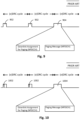
- Fig. 9 illustrates the UE idle mode operation for monitoring paging.
- Paging is used for network-initiated connection setup when the device is in RRC_IDLE.
- LTE the same mechanism as for "normal" downlink data transmission on the DL-SCH is used and the mobile device monitors the L1/L2 control signaling for downlink scheduling assignments related to paging. Therefore, a discontinuous reception (DRX) cycle (paging cycle) is defined, allowing the device to sleep most of the time and only briefly wake up to monitor the L1/L2 control signaling.
- the network configures in which frame (paging frame (PF)) and subframes (paging occasions (POs)) a device should wake up and listen for paging.
- PF paging frame
- POs paging occasions
- the 3GPP draft contributions R1-1707568 provides three proposals concerning a new physical signal/channel in MTC.
- the new physical signal/channel could be used to indicate that a UE should either wake up and monitor its MPDCCH search spaces, or keep sleeping without need to monitor its search spaces, or adjust its MPDCCH detection period.
- the new physical signal/channel occasions can be configured either based on an offset of k0 downlink subframes before the desired MPDCCH occasions, or independently of MPDCCH occasions.
- Proposal 3 the pros and cons of using a new physical signal/channel needs to be carefully considered in terms of power consumption efficiency.
- the document US 2017/215169 A1 describes a group paging method, wherein an electronic device converts, in a DRX mode, from an idle state into a wakeup state when it is time to check group paging. In the wakeup state, if a group paging message is valid, a specific function according to the group paging message is performed.
- the groups may relate to subscription services, e.g. water or gas metering services, and the function may relate to performing these services.
- the group paging DRX cycle may be periodically repeated independently of a periodic individual paging DRX cycle of the electronic device. Optionally, the group paging DRX cycle may be skipped for a preset time.
- WO 2017/079574 A1 describes methods for paging for reduced bandwidth wireless transmit/receive unites (WTRUs), wherein determining a paging narrowband (NB) is based on the most significant bits (MSBs) of the WTRU-identifier, or wherein the M-PDCCH search space to be monitored by the WTRU has a starting enhanced control channel element (ECCE) index for a WTRU group containing the WTRU.
- WTRUs reduced bandwidth wireless transmit/receive unites
- the UE may use DRX in idle mode in order to reduce power consumption.
- One PO is a subframe where there may be P-RNTI transmitted on PDCCH or MPDCCH or, for NB-loT, on NPDCCH addressing the paging message.
- P-RNTI transmitted on MPDCCH PO refers to the starting subframe of MPDCCH repetitions.
- P-RNTI transmitted on NPDCCH PO refers to the starting subframe of NPDCCH repetitions unless the subframe determined by PO is not a valid NB-loT downlink subframe. Then the first valid NB-loT downlink subframe after PO is the starting subframe of the NPDCCH repetitions.
- One PF is one Radio Frame, which may contain one or multiple PO(s).
- Paging Narrowband PBS is one narrowband, on which the UE performs the paging message reception.
- a paging cycle may be configured as DRX or eDRX cycle.
- the maximum DRX and eDRX cycles may be 10.24 seconds and two hours, 54 minutes and 46 seconds, respectively.
- a paging message may be carried in a physical downlink shared channel (PDSCH), e.g. the NPDSCH and scheduled by downlink control information (DCI) format N2 carried in NPDCCH.
- PDSCH physical downlink shared channel
- DCI downlink control information
- the 'wake-up signal' and 'go-to-sleep signal' solutions are based on the transmission of a short signal which would indicate to the radio device whether or not it would have to continue to decode the full MPDCCH (eMTC) or NPDCCH (NB-loT).
- the decoding time for the former signal is considerably shorter than for the full MPDCCH or NPDCCH, which gives a reduced UE power consumption and longer battery life.
- the 'wake-up signal' would be transmitted only when there is paging for the UE; if there is not, the 'wake-up signal' will not be transmitted (the meaning of DTX in the above agreement) and the UE would go back to sleep.
- the 'go-to-sleep signal' would be transmitted only when there is not any paging for the UE; if there is, the 'go-to-sleep signal' will not be transmitted (the meaning of DTX in the above agreement) and the UE would continue to decode NPDCCH or MPDCCH.
- Fig. 10 The 'wake-up signal' and 'go-to-sleep signal' solutions are illustrated in Fig. 10 .
- the 'wake-up signal' is used to indicate that there will be one or more paging records sent during the (e)DRX cycle that follows.
- the UE Upon receiving such a signal, the UE needs to stay up to attempt to decode the DCI format N2 carried in NPDCCH. This case is illustrated by the UE idle mode operation 1004. However, if the power control signal is not present, the UE will return to sleep mode. This case is illustrated by the UE idle mode operation 1002.
- the 'go-to-sleep signal' is used to indicate that there will be no paging record sent during the (e)DRX cycle that follows.
- the UE Upon receiving such a signal, the UE goes back to the sleep mode. This case can also be illustrated by the UE idle mode operation 1002 in Fig. 10 .
- the UE has to stay up to attempt to decode the DCI format N2 carried in NPDCCH. This case is illustrated again by the UE idle mode operation 1004.
- the 'wake-up signal' and the 'go-to-sleep signal' may therefore be regarded as power control signals.
- the decoding time for such as 'wake-up' or 'go-to-sleep signal' which may be a single bit physical signal, as illustrated by the reference numeral 1002 in Fig. 10 , is considerably shorter than the time required for decoding the full MPDCCH or NPDCCH, as shown in Fig. 9 as well as in Fig. 10 using the dotted line.
- Using a 'wake-up signal' or a 'go-to-sleep signal' therefore enables a reduced UE power consumption and longer battery life of the UE, especially for UEs in extreme coverage limited situations.
- a 'wake-up signal' is the risk for false paging. All UEs sharing a PF and PO will share the same 'wake-up signal' or 'go-to-sleep signal'. That is, if a larger number of UEs share the PF (and PO) but there is only paging of one UE, the eNodeB (eNB) will transmit the 'wake-up signal' and all these UEs will read it and continue to decode the corresponding PDCCH, e.g. the NPDCCH or MPDCCH, which holds the DCI out the (N)PDSCH transmission holding the paging message. That is, these UEs will unnecessarily read the paging message although it does not concern them and they are not being paged. This problem is called false paging.
- PDCCH e.g. the NPDCCH or MPDCCH
- a method of idle mode paging in a radio communication between a network node and a radio device is a method of sending, by a network node, a power control signal according to a discontinuous reception, DRX, cycle or paging cycle in a radio communication between the network node and a radio device according to claim 1.
- the method comprises or triggers a step of sending the power control signal for notifying a radio device which is being paged, wherein the power control signal includes an indicator that, according to a scheme, uniquely identifies a subgroup of one or more radio devices comprising at least the radio device that is being paged within a group of radio devices sharing at least the same paging frame. For example, it is proposed to add some bits of information to the power control signal to be able to differentiate which radio device, e.g. UE, in the shared PF is currently being paged to avoid or at least reduce false paging.
- the power control signal includes an indicator that, according to a scheme, uniquely identifies a subgroup of one or more radio devices comprising at least the radio device that is being paged within a group of radio devices sharing at least the same paging frame. For example, it is proposed to add some bits of information to the power control signal to be able to differentiate which radio device, e.g. UE, in the shared PF is currently being paged to avoid or at least
- the indicator added to the power control signal uniquely identifies a subgroup of radio devices out of all radio devices sharing at least the same PF, wherein the subgroup comprises the radio device that is currently being paged to reduce false paging. Accordingly, not all radio devices, e.g. UEs, sharing the same PF will have to read and continue to decode the corresponding PDCCH, e.g. the NPDCCH or MPDCCH, which holds the DCI pointing out the (N)PDSCH transmission holding the paging message, but only the radio devices belonging to the subgroup of radio devices that has been identified by the indicator. As a result, UE power consumption is reduced and battery life improved.
- Embodiments of the method according to the first general aspect may include one or more of the following aspects and/or features.
- the subgroup may comprise only the radio device that is being paged. In any case, the subgroup comprises a subset of all radio devices sharing at least the same PF.
- the situation where the subgroup in addition to the radio device that is currently being paged comprises further but not all remaining radio devices sharing at least the same PF may be beneficial in situations where there is a large number of radio devices sharing a PF and the International Mobile Subscriber Identity (IMSI) value of the device does not allow to efficiently differentiate between all radio devices within a PF based on a identifier of a certain length.
- IMSI International Mobile Subscriber Identity
- the indicator may, according to the scheme, uniquely identify a subgroup of one or more radio devices comprising at least the radio device that is being paged within a group of radio devices sharing the same paging frame (PF) and the same paging occasion (PO).
- PF paging frame
- PO paging occasion
- sharing the same paging frame may indicate or specify all radio devices configured to monitor the same PF within the DRX cycle / paging cycle.
- sharing the same paging occasion may indicate or specify all radio devices configured to monitor the same paging subframe (PO) within the PF.
- the indicator may uniquely identify the radio device which is being paged only within a group of radio devices sharing the same paging frame or only within a group of radio devices sharing the same paging frame and the same paging occasion.
- the indicator may not uniquely identify radio devices being configured to monitor different paging frames or to monitor different paging occasions.
- the number of required bits to be added as the identifier to the power control signal can be reduced.
- the indicator may comprise bits of information that are derived in accordance with the scheme or based on the scheme to be able to differentiate which radio device in the shared PF or at least which subgroup is currently being paged to avoid or at least reduce false paging.
- the indicator may comprise bits of information that are derived in accordance with the scheme from the identity of the radio device, that is currently being paged and which should be notified with the power control signal, and from the DRX parameters provided in System Information.
- the scheme may thus be a formula to determine the identifier.
- the identifier may thus be calculated according to the scheme by the network node and verified by a radio device receiving the power control signal according to the same scheme.
- the power control signal may be a physical signal, i.e. a signal sent over a physical channel, e.g. a physical downlink control channel.
- the physical downlink control channel is a MPDCCH in eMTC or a NPDCCH in NB-loT.
- the power control signal may be a physical downlink control channel signal, e.g. a MTC physical downlink control channel, MPDCCH, signal or a narrowband physical downlink control channel, NPDCCH, signal.
- the indicator may be provided as a binary sequence (bit stream, sequence of bits).
- the indicator may be derived, according to the scheme, from a radio device identity (UE_ID) used for paging the radio device.
- UE_ID radio device identity
- IMSI International Mobile Subscriber Identity
- the indicator comprises the most significant bit (msb) of the bit sequence representing the decimal integer value of UE_ID and does not comprise the least significant bit (Isb) of the bit sequence representing the decimal integer value of UE_ID.
- the bit sequence representing the indicator is shorter than the bit sequence representing the UE_ID of the radio device that is currently being paged.
- the most significant bit is the bit in a binary sequence that carries the greatest numerical value.
- the indicator may be determined according to the scheme based on the International Mobile Subscriber Identity (IMSI), the number of PFs within the radio device DRX cycle, and the number of POs (sub-frames) used within a PF.
- IMSI International Mobile Subscriber Identity
- the resulting value may be represented as a binary sequence in the power control signal. Based on these parameters, the radio devices sharing the same PF and PO may be determined and differentiated.
- the resulting decimal integer value of floor (UE_ID/(N*Ns)) may be converted in a corresponding binary sequence to represent the indicator in the physical power control signal.
- Formula 1 assigns different indicator values for a group of radio devices (UEs) sharing the same PF and the same PO(s), so that the radio device within this group that is currently being paged can be uniquely identified or alternatively, at least a subgroup of radio devices comprising the radio device that is currently being paged can be uniquely identified.
- UEs radio devices
- the indicator may be determined according to the scheme based on the IMSI, the number of PFs within the radio device DRX cycle, the number of POs used within a PF, and based on the number of paging narrowbands or paging carriers provided in the System Information.
- the resulting value may be represented as a binary sequence in the power control signal.
- the radio devices sharing the same PF and POs but that are monitoring paging on possibly a different carrier or narrowband may be determined and differentiated efficiently.
- the resulting decimal integer value of floor may be converted in a corresponding binary sequence to represent the indicator in the physical power control signal.
- Determining the indicator according to a scheme defined by Formula 2 is beneficial in situations where multiple narrowbands are used. In this case it is sufficient to differentiate in the power control signal those radio devices that share both PF and paging narrowband (PNB).
- Nn in Formula 2 corresponds to the number of paging narrowbands for P-RNTI monitored on MPDCCH.
- Nn represents the number of paging carriers (for P-RNTI monitored on NPDCCH) provided in the System Information.
- the method according to the first general aspect may further comprise the step of determining if there is a paging message for the radio device during a subsequent DRX cycle, and if so, preferably if and if only so, sending the power control signal for said radio device prior to sending the downlink assignment for paging said radio device using the PDCCH, and prior to sending the paging message for said radio device using the PDSCH.
- the power control signal would be transmitted only when there is paging for the radio device; if there is not, the power control signal will not be transmitted.
- the PDCCH may be a Narrowband PDCCH, also referred to as NPDCCH or a Machine-type communication, MTC, PDCCH, also referred to as MPDCCH.
- the method may further comprise the step of: responsive to determining that there is no paging message for said radio device during a subsequent DRX cycle, no power control signal is sent for said radio device.
- the power control signal may be a wake-up signal, since the wake-up signal would be sent (transmitted) only when there is paging for the radio device (UE); if there is not, the wake-up signal will not be transmitted (the meaning of DTX in the above agreement) and the radio device would go back to sleep.
- the power control / wake-up signal is used to indicate that there will be one or more paging records sent during the (e)DRX cycle that follows. Upon receiving such a signal, the radio device needs to stay up to attempt to decode the DCI format N2 carried in PDCCH used for paging.
- the power control signal could be used as a wake-up signal comprising the indicator so that false paging is avoided or at least reduced compared to a wake-up signal comprising no such indicator.
- the power control signal could be used in addition to a go-to-sleep signal.
- the method may further comprise the step of: responsive to determining that there is no paging message for said radio device during a subsequent DRX cycle, sending a go-to-sleep signal to said radio device for notifying said radio device that there will be no paging record sent during the subsequent DRX cycle and that said radio device may go to sleep mode.
- the go-to-sleep signal may be sent over a physical downlink control channel monitored by said radio device during the DRX cycle.
- the go-to-sleep signal which may be a single bit signal, would be transmitted only when there is not any paging for the radio device; if there is, the go-to-sleep signal will not be sent and instead the power control signal is sent including the identifier so that false paging is avoided or at least reduced.
- the method may be performed by, or by means of, the network node.
- the network node may be any device configured for radio communication with the radio device over a communication link, wherein the network node uses paging for network-initiated connection setup and/or transmits DCI to the radio device using the PDCCH, e.g. the NPDCCH or MPDCCH, which holds the DCI pointing out the PDSCH transmission holding the paging message.
- the PDCCH e.g. the NPDCCH or MPDCCH
- the network node may be embodied by a base station, an eNodeB in LTE, a gNodeB in New Radio (NR) or a relay node or any station defined above in the context of the method aspect according to the first general aspect.
- a base station an eNodeB in LTE, a gNodeB in New Radio (NR) or a relay node or any station defined above in the context of the method aspect according to the first general aspect.
- NR New Radio
- the technique may be embodied in a communication network compatible with at least one of 3GPP Long Term Evolution (LTE), LTE-Advanced (e.g., 3GPP LTE Release 10), LTE Advanced Pro (e.g. 3GPP LTE Release 13), 3GPP New Radio (NR) for the 5th Generation (5G), 3GPP Releases 13, 14 and 15 (RAN2), and 3GPP TS 36.304.
- LTE Long Term Evolution
- LTE-Advanced e.g., 3GPP LTE Release 10
- LTE Advanced Pro e.g. 3GPP LTE Release 13
- 5G 5th Generation
- RAN2 3GPP Releases 13, 14 and 15
- 3GPP TS 36.304 3GPP Term Evolution
- LTE Long Term Evolution
- LTE-Advanced e.g., 3GPP LTE Release 10
- LTE Advanced Pro e.g. 3GPP LTE Release 13
- NR
- a method of receiving, by a radio device, a power control signal in a radio communication between a network node and the radio device is a method of receiving the power control signal according to a DRX cycle or paging cycle in a radio communication between a network node and a radio device according to claim 5.
- the method comprises or triggers a step of receiving the power control signal, wherein the power control signal includes an indicator that, according to a scheme, uniquely identifies a subgroup of one or more radio devices which are being paged within a group of radio devices sharing at least the same PF.
- the radio device that is receiving the power control signal may not be the radio device which is being paged, in particular if multiple radio devices share the same PF and/or PO. However, the radio device that is receiving the power control signal comprising the indicator may determine based on the indicator whether or not said radio device is the one that is being paged.
- Embodiments of the method according to the second general aspect may include one or more of the following aspects and/or features.
- the indicator may uniquely identify according to the scheme the radio device which is being paged within a group of radio devices sharing the same PF and the same PO(s).
- the indicator uniquely identifies a subgroup of one or more radio devices comprising at least the radio device which is being paged within a group of radio devices sharing the same paging frame and the same paging occasion.
- the indicator may uniquely identify the radio device which is being paged only within a group of radio devices sharing the same PF or sharing the same PF and the same PO(s).
- the indicator may, according to the scheme, uniquely identify a subgroup of one or more radio devices comprising at least the radio device which is being paged only within a group of radio devices sharing the same paging frame or sharing the same paging frame and the same paging occasion.
- the subgroup may comprise only the radio device that is being paged.
- the indicator may be provided according to the scheme as a binary sequence and/or may be derived from a radio device identity, UE_ID, used for paging of the radio device.
- the indicator may comprise the most significant bit of the UE_ID and does not comprise the least significant bit of the UE_ID.
- the method according to the second general aspect may further comprise the step of determining, based on the received indicator and according to the scheme, whether or not the indicator identifies the radio device that is receiving the power control signal as the radio device which is being paged.
- any one of the radio devices within a group of radio devices sharing at least the same PF can determine based on the received indicator whether or not said radio device is currently being paged.
- the method according to the second general aspect may further comprise the step of: responsive to determining the radio device that is receiving the power control signal being identified as the radio device which is being paged, decoding the PDCCH which holds the DCI pointing out the PDSCH transmission holding the paging message.
- the method further comprises the step of: responsive to determining the radio device that is receiving the power control signal not being identified as the radio device which is being paged, going back to sleep mode (RRC_ldle state) without decoding the PDCCH, which holds the DCI pointing out the PDSCH transmission holding the paging message.
- only one of the radio devices within the device group that shares at least the same paging frame stays awake and continues to decode the corresponding PDCCH, e.g. the NPDCCH or MPDCCH, which holds the DCI pointing out the (N)PDSCH transmission holding the paging message, namely the radio device that has been identified by the indicator. All the other radio devices can go back to sleep mode in order to save power.
- the corresponding PDCCH e.g. the NPDCCH or MPDCCH
- the PDCCH may be a Narrowband PDCCH, also referred to as NPDCCH, or a Machine-type communication, MTC, PDCCH, also referred to as MPDCCH.
- NPDCCH Narrowband PDCCH
- MTC Machine-type communication
- MPDCCH MPDCCH
- the step of determining, based on the received indicator and according to the scheme, whether or not the indicator identifies the radio device that is receiving the power control signal as the radio device which is being paged may further comprise the following steps: a first step of determining a reference indicator according to the scheme based on the identity used for paging of the radio device that has received the power control signal; a second step of comparing the determined reference indicator with the indicator received with the power control signal.; and a third step of determining whether the indicator identifies the radio device that has received the power control signal as the radio device which is being paged. This is the case if the indicator equals the determined reference indicator. This is not the case if the indicator does not equal the determined reference indicator.
- the identity of the radio device may be derived from the IMSI.
- the reference indicator is determined according to the same scheme as the indicator received from the network node.
- the receiving radio device uses its own identity used for paging for determining the reference indicator. If said radio device is the one currently being paged by the network node, then the network node would have used also the same radio device identity for determining the indicator according to the scheme. In this case, the values of indicator and reference indicator would be identical. If said radio device is not the one currently being paged by the network node, then the network node would have used the identity of a different radio device within the device group for determining the indicator. The values of indicator and reference indicator would be different.
- the second general aspect may comprise the step of determining a reference indicator.
- the reference indicator may be determined according to the scheme based on the International Mobile Subscriber Identity (IMSI) the number of paging frames within the radio device DRX cycle, and the number of paging occasions used within a paging frame.
- IMSI International Mobile Subscriber Identity
- the resulting value may be represented as a binary sequence in the power control signal.
- the reference indicator may be determined according to the scheme on the International Mobile Subscriber Identity, IMSI, the number of paging frames within the radio device DRX cycle, the number of paging occasions used within a paging frame, and based on the number of paging narrowbands or paging carriers provided in System Information.
- the resulting value may be represented as a binary sequence in the power control signal.
- the received power control signal may be a wake-up signal
- the method further comprising the step of: responsive to determining that no wake-up signal has been sent according to the DRX cycle, going back to sleep mode.
- the power control signal serves as a wake-up signal for the radio device that is being paged. If no wake-up signal is received or if the indicator does not match, the radio device goes back to sleep mode.
- the method may further comprise the steps of receiving, by the radio device, a go-to-sleep signal indicating to said radio device that there will be no paging record sent during the subsequent DRX cycle, and responsive to receiving the go-to-sleep signal, going to sleep mode.
- the radio device may also receive a go-to-sleep signal over the same PDCCH used for paging.
- the go-to-sleep signal may be a single-bit signal, i.e. comprising no indicator in contrast to the power control signal.
- the method may be performed by, or by means of, a radio device.
- the radio device may be embodied by a user equipment (UE), a machine-type device, a terminal or any station defined above in the context of the method aspect according to the second general aspect.
- the radio device may be a UE according to the 3GPP specification.
- the radio device may be embodied by any device configured for radio communication with the network node over a communication link, wherein the radio device is configured to wake up according to a DRX cycle or paging cycle.
- the radio device may be embodied by any device configured for radio communication using radio access technologies, in particular where a power control signal is used.
- the radio device may be embodied by a UE according to the new UE categories (Cat-M1, Cat-M2), supporting reduced bandwidth of 6 physical resource blocks (PRBs) (up to 24 PRBs for Cat-M2),
- the radio device may be embodied by a Narrowband IoT (NB-loT) UE providing a new radio interface (and UE categories, Cat-NB1 and Cat-NB2), in particular according to the LTE enhancements introduced in 3GPP Release 13,14 and 15.
- NB-loT Narrowband IoT
- the method according to the second general aspect may further comprise any feature and aspects and/or achieve any advantage disclosed in the context of the method according to the first general aspect and/or may comprise one or more steps corresponding to any of the steps of the method according to the first general aspect.
- a computer program product comprises program code portions for performing any one of the steps of the method aspects disclosed herein when the computer program product is executed by one or more computing devices.
- the computer program product may be stored on a computer-readable recording medium.
- the computer program product may also be provided for download via a data network, e.g. via the radio network and/or via the Internet.
- the method may be encoded in a Field-Programmable Gate Array (FPGA) and/or an Application-Specific Integrated Circuit (ASIC), or the functionality may be provided for download by means of a hardware description language.
- FPGA Field-Programmable Gate Array
- ASIC Application-Specific Integrated Circuit
- a device for sending a power control signal, preferably according to a discontinuous reception (DRX) cycle, in a radio communication between the device and a radio device is provided.
- the device is configured to perform or trigger the steps of the method according to the first general aspect.
- the device may comprise a sending unit for sending, to the radio device, the power control signal for notifying a radio device which is being paged, wherein the power control signal includes an indicator that, according to a scheme, uniquely identifies a subgroup of one or more radio devices comprising at least the radio device that is being paged within a group of radio devices sharing at least the same paging frame.
- a device for receiving a power control signal, preferably according to a DRX cycle, in a radio communication between a network node and the radio device is provided.
- the device may be configured to perform the method according to the second general aspect.
- the device comprises a receiving unit for receiving, from the network node, the power control signal, wherein the power control signal includes an indicator that, according to a scheme, uniquely identifies a radio device which is being paged within a group of radio devices sharing at least the same PF.
- a device for sending a power control signal preferably according to a DRX cycle in a radio communication between the device and a radio device.
- the device comprises a processor and a memory, said memory containing instructions executable by said processor whereby the device is operative to send, to the radio device, the power control signal for notifying a radio device which is being paged, wherein the power control signal includes an indicator that, according to a scheme, uniquely identifies a subgroup of one or more radio devices comprising at least the radio device that is being paged within a group of radio devices sharing at least the same PF.
- a device for receiving a power control signal, preferably according to a DRX cycle, in a radio communication between a network node and the radio device comprises a processor and a memory, said memory containing instructions executable by said processor whereby the device is operative to receive, from the network node, the power control signal, wherein the power control signal includes an indicator that, according to a scheme, uniquely identifies a radio device which is being paged within a group of radio devices sharing at least the same PF.
- a device for receiving a power control signal, preferably according to a DRX cycle, in a radio communication between a network node and the radio device comprises a processor and a memory, said memory containing instructions executable by said processor whereby the device is operative to receive, from the network node, the power control signal, wherein the power control signal includes an indicator that, according to a scheme, uniquely identifies a subgroup of one or more radio devices comprising at least the radio device which is being paged within a group of radio devices sharing at least the same PF.
- a device for sending a power control signal, preferably according to a DRX, cycle, in a radio communication between the device and a radio device is provided.
- the device may comprise one or more modules for performing the method according to the first general aspect.
- the device comprises a sending module for sending, to the radio device, the power control signal for notifying a radio device which is being paged, wherein the power control signal includes an indicator that, according to a scheme, uniquely identifies a subgroup of one or more radio devices comprising at least the radio device that is being paged within a group of radio devices sharing at least the same PF.
- a device for receiving a power control signal, preferably according to a DRX, cycle, in a radio communication between a network node and the radio device is provided.
- the device may comprise one or more modules for performing the method according to the second general aspect.
- the device comprises a receiving module for receiving, from the network node, the power control signal, wherein the power control signal includes an indicator that, according to a scheme, uniquely identifies a radio device which is being paged within a group of radio devices sharing at least the same PF.
- a device for receiving a power control signal, preferably according to a DRX, cycle, in a radio communication between a network node and the radio device is provided.
- the device may comprise one or more modules for performing the method according to the second general aspect.
- the device comprises a receiving module for receiving, from the network node, the power control signal, wherein the power control signal includes an indicator that, according to a scheme, uniquely identifies a subgroup of one or more radio devices comprising at least the radio device which is being paged within a group of radio devices sharing at least the same PF.
- the devices and/or the stations may further include any feature disclosed in the context of the method aspects. Particularly, any one of the units and modules, or a further unit or module, may be configured to perform or initiate one or more of the steps of any one of the method aspects.
- a system for sending and receiving a power control signal, preferably according to a DRX cycle, in a radio communication between a network node and a radio device comprises a device for sending a power control signal, preferably according to a DRX cycle, as described in this document and at least one device for receiving a power control signal, preferably according to a DRX cycle, as described in this document.
- Some of the advantages achieved by the methods and the corresponding radio network nodes and radio devices may be compiled as enabling reduced power consumptions of radio devices operative for idle mode paging.
- Fig. 1 shows a schematic block diagram of a device 100 for sending a power control signal according to a DRX cycle in a radio communication between the device 100 and a radio device 200, as shown in Fig. 2 .
- the device 100 comprises a sending module 102 for sending, to the radio device 200, the power control signal for notifying a radio device which is being paged, wherein the power control signal includes an indicator that, according to a scheme, uniquely identifies a subgroup of one or more radio devices comprising at least the radio device that is being paged within a group of radio devices sharing at least the same paging frame.
- the device 100 may be connected to and/or part of a radio network, preferably a 5G NR network.
- the device 100 may be any network node or device configured for radio communication with the radio device over a communication link.
- the device 100 is configured to use paging for network-initiated connection setup and/or transmits DCI to the radio device using the PDCCH, e.g. the NPDCCH or MPDCCH, which holds the downlink control information pointing out the PDSCH transmission holding the paging message.
- the PDCCH e.g. the NPDCCH or MPDCCH
- the network node or device 100 may be embodied by a network node supporting MPDCCH in eMTC or NPDCCH in NB-loT or any eNodeB, station or network node defined above in the context of the method aspect according to the first general aspect.
- Fig. 2 shows a schematic block diagram of a device 200 for receiving a power control signal according to a DRX cycle in a radio communication between a network node 100 and the device 200.
- the device 200 comprises a receiving module 202 for receiving, from the network node 100, the power control signal.
- the power control signal includes an indicator that, according to a scheme, uniquely identifies a radio device which is being paged within a group of radio devices sharing at least the same paging frame.
- the device 200 may be any device configured for radio communication with the network node over a communication link, wherein the radio device is configured to wake up according to a discontinuous reception, DRX, cycle or paging cycle.
- the radio device may be embodied by a user equipment (UE), a machine type device, a terminal or any station defined above in the context of the method aspect according to the second general aspect.
- the radio device may be a UE according to the 3GPP specification.
- the radio device may be embodied by any device configured for radio communication with the network node over a communication link.
- the radio device may be embodied by any device configured for radio communication using radio access technologies, in particular where a power control signal is used.
- the radio device may be embodied by a UE according to the new UE categories (Cat-M1, Cat-M2), supporting reduced bandwidth of 6 physical resource blocks (PRBs) (up to 24 PRBs for Cat-M2),
- the radio device may be embodied by a Narrowband IoT (NB-loT) UE providing a new radio interface (and UE categories, Cat-NB1 and Cat-NB2), in particular according to the LTE enhancements introduced in 3GPP Release 13,14 and 15.
- NB-loT Narrowband IoT
- modules of the device 100 and the device 200 may be implemented by units configured to provide the corresponding functionality.
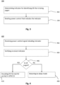
- Fig. 3 shows a flowchart for a method of sending, by a network node, a power control signal according to a DRX cycle in a radio communication between a network node and a radio device.
- the method 300 comprises a step of sending 304 to the radio device, a power control signal for notifying a radio device which is being paged, wherein the power control signal includes an indicator that, according to a scheme, uniquely identifies a subgroup of one or more radio devices comprising at least the radio device that is being paged within a group of radio devices sharing at least the same paging frame.
- the method may further comprise a step of determining 302 an indicator based on the scheme for identifying the radio device that is being paged. This will be described in more detail below.
- the method 300 may be performed by the device 100.
- the module 102 may perform the step 304.
- the device 100 may have a determination module (not shown) for computing the indicator in order to perform the step 302.
- Fig. 4 shows a flowchart for a method of receiving, by a radio device, a power control signal according to a DRX cycle in a radio communication between a network node and the radio device.
- the method 400 comprises a step of receiving 402, from the network node, the power control signal including the indicator.
- the indicator according to a scheme, uniquely identifies a radio device which is being paged within a group of radio devices sharing at least the same paging frame.
- the method 400 further comprises a steps of verifying 404 the received indicator and determining 406, whether or not the indicator identifies this particular radio device as the one that is currently being paged. These steps comprise determining, based on the received indicator and according to the scheme, whether or not the indicator identifies the radio device that is receiving the power control signal as the radio device which is being paged. As noted above, all radio devices sharing the same PF and/or PO may receive the power control signal, whereas only one of these radio devices is currently being paged.
- the radio device that has received the indicator with the power control signal can now determine in step 404 and subsequently in step 406, whether or not the indicator identifies this particular radio device as the one that is currently being paged or not.
- the method 400 further comprises steps 408 und 410.
- step 408 responsive to determining in step 406 that the radio device is not identified as the radio device which is being paged, the radio device returns to sleep mode without decoding the PDCCH which holds the DCI pointing out the PDSCH transmission holding the paging message.
- step 410 responsive to determining in step 406 that the radio device is identified as the radio device which is being paged, the radio device continues to decode the PDCCH which holds the DCI pointing out the PDSCH transmission holding the paging message.
- NPDCCH or MPDCCH may be used as the PDCCH.
- Fig. 5 shows a schematic block diagram for an embodiment of a device 500 for sending a power control signal according to a DRX cycle in a radio communication between the device 500 and a radio device.
- the device 500 may comprise a radio interface 502 for radio communication with at least a radio device 600 that is configure to receive the power control signal, one or more processor circuits 504 for performing the method 300 and memory 506 coupled to the processor circuits 504.
- the memory 506 is encoded with instructions that implement the module 102.
- the one or more processor circuits 504 may be a combination of one or more of a microprocessor, controller, microcontroller, central processing unit, digital signal processor, application specific integrated circuit, field programmable gate array, or any other suitable computing device, resource, or combination of hardware, software and/or encoded logic operable to provide, either alone or in conjunction with other station components, such as the memory 506, station functionality.
- the one or more processor circuits 504 may execute instructions stored in the memory 506.
- Such functionality may include providing various features and steps discussed herein, including any of the benefits disclosed herein.
- Fig. 6 shows a schematic block diagram for an embodiment of a device 600 for receiving a power control signal according to a DRX cycle in a radio communication between a network node 500 and the device 600.
- the second device 600 comprises a radio interface 602 for radio communication with at least the network node (device 500), one or more processor circuits 604 for performing the method 400 and memory 606 coupled to the processor circuits 604.
- the memory 606 is encoded with instructions to implement the modules 202.
- the one or more processor circuits 604 may be a combination of one or more of a microprocessor, controller, microcontroller, central processing unit, digital signal processor, application specific integrated circuit, field programmable gate array, or any other suitable computing device, resource, or combination of hardware, software and/or encoded logic operable to provide, either alone or in conjunction with other station components, such as the memory 606, station functionality.
- the one or more processor circuits 604 may execute instructions stored in the memory 606.
- Such functionality may include providing various features and steps discussed herein, including any of the benefits disclosed herein.
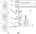
- Fig. 7 illustrates an exemplary communication system 700 for sending and receiving a power control signal in a radio communication between a network node 500 and one or more radio devices 600, wherein embodiments herein may be employed or applied.
- the system 700 comprises a network node 500, configured to send a power control signal 702 in order to page a respective radio device.
- the system 700 further comprises multiple radio devices 600, hereinafter referred to as UEs 600 configured to receive the power control signal according to the DRX cycle.
- paging is used for network initiated connection setup.
- UEs in RRC Idle mode use a DRX cycle also known as paging cycle to reduce power consumption. This DRX cycle determines how frequently UEs check for paging messages.
- the default DRX cycle is broadcast within System Information Block 2 (SIB 2).
- the network node 500 is configured, as explained in connection with Fig. 10 , to send a power control signal 702 to indicate that there will be one or more paging records sent during the (e) DRX cycle that follows.
- the power control signal 702 is received by a group 710 of UEs 600.
- the power control signal 702 according to the embodiment now includes an indicator 704.
- the indicator according to a scheme 706 or 708, uniquely identifies a subgroup of one or more radio devices comprising at least the radio device that is being paged within a group 710 of radio devices 600 that all receive the same power control signal 702.
- the schemes 706 und 708 used for determining the indicator 704 will be described in more detail below. First, the problem of false paging will be described in more detail based on the usage of a wake-up signal as known in the art.
- paging frame the radio frame in which a UE wakes up.
- UEs do not remain awake in all sub frames. Instead, an UE wakes up in a specific subframe within a radio frame.
- These specific subframes within a Paging Frame when UE wakes up are referred to as paging occasions (POs). There may be only one PO within a PF.
- UE makes use of the look up table.
- the intersection of i_s and Ns values in the look up table shows in which subframe(s) UE will wake up.
- UE_ID The UE identity, UE_ID, is determined as follows: UE ID:
- the indicator 704 can differentiate between UEs that share the same PF and the same PO. For example, floor(UE_ID/(N*Ns)) is equal to 0, 3, and 2 for these cases and could be used to separate these UEs and avoid false paging.
- another scheme 708 is used to compute the indicator 704.
- Nn corresponds to the number of paging narrowbands.
- the proposed power control signal differentiation as proposed here may be used as a complementary technique which can minimize false paging when less narrowbands are being used.
- the indicator value can be computed based on Formula 2, wherein in this case Nn in Formula 2 corresponds to the number of paging carriers (for P-RNTI monitored on NPDCCH) provided in System Information instead of to the number of paging narrowbands.
- the paging carrier is determined by the paging carrier with the smallest index n (0 ⁇ n ⁇ Nn-1) fulfilling the following equation: floor UE _ ID / N * Ns mod W ⁇ W 0 + W 1 + ... + W n .
- the network node 500 will first determine if there is a paging message for any of the radio devices during a subsequent DRX cycle. If so, the network node 500 will first determine the indicator value for the respective radio device that should be paged by computing the indicator value according to Formula 1 or according to Formula 2, wherein the particular UE_ID of the respective radio device that should be paged is used. Thus, the bit sequence of the indicator 704 that is added to the power control signal 702 will depend on which one of the UEs shown in Fig. 7 is currently paged.
- the network node 500 will send the power control signal 702 according to the paging cycle prior to sending the downlink assignment for paging using the PDCCH and prior to sending the paging message using the PDSCH.
- all three UEs will receive the power control signal 702 including the indicator 704.
- Each of the UEs is configured to determine, based on the received indicator 704 and according to the scheme, whether or not the indicator identifies the radio device that is receiving the power control signal as the radio device which is being paged.
- each of the UEs is configured to determine a reference indicator using the same scheme/formula as the network node, e.g. using Formula 1 or Formula 2.
- the receiving radio device uses its own identity used for paging for determining the value for UE_ID as used in the scheme.
- the other parameters, e.g. N, Ns, Nn have the same values for all UEs.
- the power control signal may be used as a wake-up signal.
- the power control signal may be used in addition to a go-to-sleep signal.
- Such a go-to-sleep signal would be transmitted over the same physical channel but only when there is not any paging for the radio device.
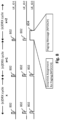
- Fig. 8 illustrates an example of UE idle mode operation of the three UE as described in Fig. 7 .
- the UEs 500 sharing the same PF and PO wake up in the same designated time window to check whether there is a power control signal 702 sent from the network node 500.
- This UE activity is illustrated with the reference numeral 802.
- the power control signal is used to indicate that there will be one or more paging records sent during the (e)DRX cycle that follows. If a UE determines that there was no power control signal, the UE would go back to sleep. This is the case in the first two DRX (paging) cycles "x" and "x+1". However, in the third DRX cycle "x+2", a paging signal is received by all of the UEs. Each of the UEs determines, based on the received indicator included in the power control signal, whether or not the indicator matched the UE's reference indicator. This is only the case for the UE the idle mode operation of which is illustrated with the lowest sub diagram in Fig. 8 .
- the technique can reduce control signaling.
- the technique can be embodied to distinguish between persistent and rapidly changing control parameters, and/or to distinguish between supported and unsupported control parameters.
- Embodiments reduce an amount of radio resources needed for the transmission of downlink control information. For example, the amount of radio resources for control signaling are halved. Furthermore, e.g., at the same time, embodiments allow for more detailed control information.
Landscapes
- Engineering & Computer Science (AREA)
- Computer Networks & Wireless Communication (AREA)
- Signal Processing (AREA)
- Mobile Radio Communication Systems (AREA)
Claims (12)
- Verfahren (300) zum Senden eines Leistungssteuersignals durch einen Netzknoten (100; 500) gemäß einem diskontinuierlichen Empfangszyklus, DRX-Zyklus, in einer Funkkommunikation zwischen dem Netzknoten (100; 500) und einer Funkvorrichtung (200; 600), wobei das Verfahren (300) Folgendes umfasst oder auslöst:Senden (304) des Leistungssteuersignals (702) zum Benachrichtigen der Funkvorrichtung (200; 600), die durch Paging bzw. Funkruf aufgerufen wird, wobei das Leistungssteuersignal (702) einen Indikator (704) enthält, der gemäß einem Schema (706; 708) eine Untergruppe von einer oder mehreren Funkvorrichtungen (200; 600) eindeutig angibt, die mindestens die Funkvorrichtung (200; 600) umfasst, die innerhalb einer Gruppe (710) von Funkvorrichtungen (200; 600) durch Paging aufgerufen wird, die sich mindestens denselben Paging-Rahmen teilen,wobei das Verfahren (300) dadurch gekennzeichnet ist, dassder Indikator (704) entweder gemäß dem Schema (706) bestimmt wird durch die Formel:

wobei floor () eine Abrundungsfunktion ist, UE_ID die Identität der Funkvorrichtung ist, N die Anzahl der Paging-Rahmen innerhalb des DRX-Zyklus der Funkvorrichtung ist und Ns die Anzahl der innerhalb eines Paging-Rahmens verwendeten Paging-Anlässe ist; oderder Indikator (704) gemäß dem Schema (708) und ferner basierend auf der Anzahl von Paging-Schmalbändern oder Paging-Trägern, die in Systeminformationen angegeben sind, bestimmt wird, und wobei der Indikator (704) gemäß dem Schema (708) bestimmt wird durch die Formel: wobei floor () eine Abrundungsfunktion ist, UE_ID die Identität der Funkvorrichtung ist, N die Anzahl der Paging-Rahmen innerhalb des DRX-Zyklus der Funkvorrichtung ist, Ns die Anzahl der Paging-Anlässe ist, die innerhalb eines Paging-Rahmens verwendet werden, und Nn die Anzahl der Paging-Schmalbänder oder Paging-Träger ist.
 - Verfahren (300) nach Anspruch 1, wobei mindestens eines der folgenden Merkmale vorliegt:- der Indikator (704) gemäß dem Schema (706; 708) eindeutig eine Untergruppe von einer oder mehreren Funkvorrichtungen (200; 600) angibt, die mindestens die Funkvorrichtung (200; 600) umfasst, die innerhalb einer Gruppe (710) von Funkvorrichtungen (200; 600), die sich denselben Paging-Rahmen und denselben Paging-Anlass teilen, durch Paging aufgerufen wird;- der Indikator (704) gemäß dem Schema (706; 708) eindeutig eine Untergruppe von einer oder mehreren Funkvorrichtungen (200; 600) umfasst, die mindestens die Funkvorrichtung (200; 600) umfasst, die nur innerhalb einer Gruppe (710) von Funkvorrichtungen (200; 600) gerufen wird, die denselben Paging-Rahmen oder denselben Paging-Rahmen und denselben Paging-Anlass nutzen;- die Untergruppe umfasst nur die Funkvorrichtung (200; 600), die durch Paging aufgerufen wird;- der Indikator (704) nach dem Schema (706; 708) als binäre Sequenz angegeben wird;- der Indikator (704) stammt von einer Funkvorrichtungsidentität, UE_ID, die für das Paging der Funkvorrichtung (200; 600) verwendet wird, und den DRX-Parametern, die in den Systeminformationen angegeben sind;- der Indikator (704) gemäß dem Schema (706; 708) basierend auf der International Mobile Subscriber Identity, IMSI, der Anzahl der Paging-Rahmen innerhalb des DRX-Zyklus der Funkvorrichtung und der Anzahl der innerhalb eines Paging-Rahmens verwendeten Paging-Anlässe bestimmt wird; und- der Indikator (704) das höchstwertige Bit der UE_ID umfasst und nicht das niedrigstwertige Bit der UE_ID.
- Verfahren (300) nach einem der Ansprüche 1 bis 2, das außerdem Folgendes umfasst: in Reaktion auf das Bestimmen, dass es eine Paging-Nachricht für die Funkvorrichtung (200; 600) während eines nachfolgenden DRX-Zyklus gibt, Senden des Leistungssteuersignals (702) für die Funkvorrichtung (200; 600) vor dem Senden der Abwärtsstrecken-Zuweisung für das Paging der Funkvorrichtung (200; 600) unter Verwendung des physikalischen Abwärtsstrecken-Steuerkanals, PDCCH, und vor dem Senden der Paging-Nachricht für die Funkvorrichtung (200; 600) unter Verwendung des physikalischen gemeinsam genutzten Abwärtsstrecken-Kanals, PDSCH,
optional mindestens eines der folgenden Elemente umfassend:- in Reaktion auf das Bestimmen, dass es während eines nachfolgenden DRX-Zyklus keine Paging-Nachricht für die Funkvorrichtung (200; 600) gibt, kein Leistungssteuerungssignal (702) für die Funkvorrichtung (200; 600) gesendet wird, wobei das Leistungssteuerungssignal (702) optional ein Wecksignal ist; und- in Reaktion auf das Bestimmen, dass es während eines nachfolgenden DRX-Zyklus keine Paging-Nachricht für die Funkvorrichtung (200; 600) gibt, Senden eines Go-to-Sleep-Signals an die Funkvorrichtung (200; 600), um die Funkvorrichtung (200; 600) zu benachrichtigen, dass während des nachfolgenden DRX-Zyklus kein Paging-Datensatz gesendet wird und dass die Funkvorrichtung (200; 600) in den Schlafmodus gehen kann, wobei das Go-to-Sleep-Signal optional über einen physikalischen Abwärtsstrecken-Kontrollkanal, PDCCH, gesendet wird, der von der Funkvorrichtung (200; 600) während des DRX-Zyklus überwacht wird, und/oder wobei das Go-to-Sleep-Signal ein Einzelbitsignal ist. - Verfahren (300) nach einem der Ansprüche 1 bis 3, wobei das Leistungssteuersignal (702) eines der folgenden Signale ist: ein Signal eines physikalischen Abwärtsstrecken-Kontrollkanals, PDCCH-Signal bzw. "physical downlink control channel"-Signal, ein Signal einer maschinellen Kommunikation, MTC bzw. "machine-type communication", eines physikalischen Abwärtsstrecken-Kontrollkanals, PDCCH-Signal bzw. "physical downlink control channel", kurz MPDCCH-Signal, oder ein physikalisches Schmalband-Abwärtsstrecken-Kontrollkanal, NPDCCH-Signal bzw. "narrowband physical downlink control channel"-Signal.
- Verfahren (400) zum Empfangen eines Leistungssteuersignals (702) durch eine Funkvorrichtung (200; 600) gemäß einem diskontinuierlichen Empfangszyklus, DRX-Zyklus, in einer Funkkommunikation zwischen einem Netzwerkknoten (100; 500) und der Funkvorrichtung (200; 600), wobei das Verfahren (400) das umfasst oder auslöst:Empfangen (402) des Leistungssteuersignals (702), wobei das Leistungssteuersignal (702) einen Indikator (704) enthält, der gemäß einem Schema (706; 708) eine Untergruppe von einer oder mehreren Funkvorrichtungen (200; 600) eindeutig angibt, die mindestens die Funkvorrichtung (200; 600) umfasst, die innerhalb einer Gruppe (710) von Funkvorrichtungen (200; 600), die sich mindestens denselben Paging-Rahmen teilen, durch Paging aufgerufen wird;Bestimmen (406), basierend auf dem empfangenen Indikator (704) und gemäß dem Schema (706; 708), ob der Indikator (704) die Funkvorrichtung (200; 600), die das Leistungssteuersignal (702) empfängt, als die Funkvorrichtung (200; 600), die durch Paging aufgerufen wird, identifiziert oder nicht, wobei das Bestimmen (406) ferner Folgendes umfasst:Bestimmen eines Referenzindikators gemäß dem Schema (706; 708), basierend auf der Identität, die für das Paging bzw. den Funkruf der Funkvorrichtung (200; 600) verwendet wird, die das Leistungssteuersignal (702) empfangen hat, wobei der Referenzindikator gemäß dem Schema (706; 708) bestimmt wird, basierend auf der International Mobile Subscriber Identity, IMSI, der Anzahl der Paging-Rahmen innerhalb des DRX-Zyklus der Funkvorrichtung und der Anzahl der innerhalb eines Paging-Rahmens verwendeten Paging-Anlässe;Vergleich des bestimmten Referenzindikators mit dem Indikator (704), der mit dem Leistungssteuersignal (702) empfangen wurde;Bestimmen, dass der Indikator (704) die Funkvorrichtung (200; 600), die das Leistungssteuersignal (702) empfangen hat, als die Funkvorrichtung (200; 600) identifiziert, die gerade durch Paging aufgerufen wird, wenn der Indikator (704) gleich dem bestimmten Referenzindikator ist; undBestimmen, dass der Indikator (704) die Funkvorrichtung (200; 600), die das Leistungssteuersignal (702) empfangen hat, nicht als die Funkvorrichtung (200; 600) identifiziert, die gerade durch Paging aufgerufen wird, wenn der Indikator (704) nicht gleich der bestimmten Referenzindikator ist,wobei das Verfahren (400) dadurch gekennzeichnet ist, dassentweder wird der Referenzindikator nach dem Schema (706) durch die Formel bestimmt:
 oder der Referenzindikator gemäß dem Schema (708) und ferner basierend auf der Anzahl der in den Systeminformationen angegebenen Paging-Schmalbänder oder Paging-Träger bestimmt wird, undwobei der Referenzindikator nach dem Schema (708) durch die Formel bestimmt wird:
- Verfahren (400) nach Anspruch 5, wobei das Leistungssteuersignal (702) eines der folgenden Signale ist: ein Signal eines physikalischen Abwärtsstrecken-Kontrollkanals, PDCCH-Signal bzw. "physical downlink control channel"-Signal, ein Signal einer maschinellen Kommunikation, MTC bzw. "machine-type communication", eines physikalischen Abwärtsstrecken-Kontrollkanals, PDCCH-Signal bzw. "physical downlink control channel", kurz MPDCCH-Signal, oder ein physikalisches Schmalband-Abwärtsstrecken-Kontrollkanal, NPDCCH-Signal bzw. "narrowband physical downlink control channel"-Signal.
- Verfahren (400) nach Anspruch 5 oder 6, das ferner umfasst:in Reaktion auf das Bestimmen (406), dass die Funkvorrichtung (200; 600), die das Leistungssteuersignal (702) empfängt, als die Funkvorrichtung (200; 600), die durch Paging aufgerufen wird, identifiziert wird, Dekodieren (410) des physikalischen Abwärtsstrecken-Steuerkanals, PDCCH, der die Abwärtsstrecken-Steuerinformationen, DCI, enthält und auf die Übertragung des gemeinsam genutzten physikalischen Abwärtsstrecken-Kanals, PDSCH, hinweist, der die Paging-Nachricht enthält; undin Reaktion auf das Bestimmen (406), dass die Funkvorrichtung (200; 600), die das Leistungssteuersignal (702) empfängt, nicht als die Funkvorrichtung (200; 600), die durch Paging aufgerufen wird, identifiziert wird, in den Schlafmodus geht (408), ohne den physikalischen Abwärtsstrecken-Steuerkanal, PDCCH, zu dekodieren, der die Abwärtsstrecken-Steuerinformationen, DCI, enthält, und auf die Übertragung des physikalischen gemeinsam genutzten Abwärtsstrecken-Kanals, PDSCH, hinweist, der die Paging-Nachricht enthält.
- Verfahren (400) nach einem der Ansprüche 5 bis 7, wobei der Referenzindikator gemäß dem Schema (706; 708) basierend auf der internationalen Mobilteilnehmeridentität, IMSI, der Anzahl der Paging-Rahmen innerhalb des DRX-Zyklus der Funkvorrichtung und der Anzahl der innerhalb eines Paging-Rahmens verwendeten Paging-Anlässe bestimmt wird.
- Verfahren (400) nach einem der Ansprüche 5 bis 8, bei dem mindestens eines der folgenden Merkmale vorliegt:- das empfangene Leistungssteuersignal (702) ist ein Aufwecksignal, wobei das Verfahren (400) ferner den Schritt umfasst, als Reaktion auf das Bestimmen, dass kein Aufwecksignal gemäß dem DRX-Zyklus gesendet wurde, in den Schlafmodus zurückzugehen; und- das Verfahren umfasst ferner das Empfangen eines Go-to-Sleep-Signals durch die Funkvorrichtung (200; 600), das der Funkvorrichtung (200; 600) angibt, dass während des nachfolgenden DRX-Zyklus kein Paging-Datensatz gesendet wird, und als Reaktion auf das Empfangen des Go-to-Sleep-Signals das Einschalten des Schlafmodus.
- Computerprogrammprodukt, das Programmcodeabschnitte zum Durchführen der Schritte nach einem der Ansprüche 1 bis 4 oder 5 bis 9 umfasst, wenn das Computerprogrammprodukt auf einer oder mehreren Computervorrichtungen (504; 604) ausgeführt wird, wobei das Computerprogrammprodukt optional auf einem computerlesbaren Aufzeichnungsmedium (506; 606) gespeichert ist.
- Vorrichtung (100; 200), die ausgebildet ist, die Schritte eines der Ansprüche 1 bis 4 oder eines der Ansprüche 5 bis 9 durchzuführen.
- System (700) zum Senden und Empfangen eines Leistungssteuerungssignals (702) gemäß einem diskontinuierlichen Empfangszyklus, DRX-Zyklus, in einer Funkkommunikation zwischen einem Netzknoten (100; 500) und einer Funkvorrichtung (200; 600), wobei das System Folgendes umfasst:- eine Vorrichtung (100), die ausgebildet ist, die Schritte nach einem der Ansprüche 1 bis 4 durchzuführen; und- mindestens eine Vorrichtung (200), die ausgebildet ist, die Schritte nach einem der Ansprüche 5 bis 9 durchzuführen.
Applications Claiming Priority (2)
| Application Number | Priority Date | Filing Date | Title |
|---|---|---|---|
| US201762544082P | 2017-08-11 | 2017-08-11 | |
| PCT/EP2018/071167 WO2019030143A1 (en) | 2017-08-11 | 2018-08-03 | REST MODE RADIO-RESEARCH TECHNIQUE IN A RADIO COMMUNICATION BETWEEN A NETWORK NODE AND A RADIO DEVICE |
Publications (4)
| Publication Number | Publication Date |
|---|---|
| EP3665984A1 EP3665984A1 (de) | 2020-06-17 |
| EP3665984B1 true EP3665984B1 (de) | 2024-05-29 |
| EP3665984C0 EP3665984C0 (de) | 2024-05-29 |
| EP3665984B8 EP3665984B8 (de) | 2024-07-17 |
Family
ID=63165351
Family Applications (1)
| Application Number | Title | Priority Date | Filing Date |
|---|---|---|---|
| EP18752727.0A Active EP3665984B8 (de) | 2017-08-11 | 2018-08-03 | Technik für den funkbetrieb im leerlaufmodus in einer funkkommunikation zwischen einem netzknoten und einem funkgerät |
Country Status (3)
| Country | Link |
|---|---|
| US (2) | US12127159B2 (de) |
| EP (1) | EP3665984B8 (de) |
| WO (1) | WO2019030143A1 (de) |
Families Citing this family (16)
| Publication number | Priority date | Publication date | Assignee | Title |
|---|---|---|---|---|
| CN112514464B (zh) * | 2018-08-10 | 2025-02-18 | 苹果公司 | 用于增强型机器类型通信(eMTC)和窄带物联网(NB-IOT)的唤醒信号子分组 |
| WO2020089427A1 (en) | 2018-11-01 | 2020-05-07 | Telefonaktiebolaget Lm Ericsson (Publ) | Wake-up signalling in a wireless communication system |
| US11265700B2 (en) * | 2018-11-30 | 2022-03-01 | Qualcomm Incorporated | Methods and systems for detecting and responding to paging channel attacks |
| US11647460B2 (en) * | 2018-12-26 | 2023-05-09 | Mediatek Singapore Pte. Ltd. | Method and apparatus for indicating power saving information in mobile communications |
| CN111756503B (zh) * | 2019-03-29 | 2023-04-18 | 华为技术有限公司 | 一种信号检测方法及设备 |
| WO2020222509A1 (ko) | 2019-05-02 | 2020-11-05 | 삼성전자 주식회사 | 무선 통신 시스템에서 단말의 전력 절약을 위한 방법 및 장치 |
| CN114025417B (zh) * | 2019-07-05 | 2025-03-18 | 展讯通信(上海)有限公司 | 进入睡眠的方法及装置、存储介质、用户设备 |
| WO2021016336A1 (en) * | 2019-07-23 | 2021-01-28 | Kyocera Corporation | Scheduled device-specific synchronization signals |
| WO2021018531A1 (en) * | 2019-08-01 | 2021-02-04 | Telefonaktiebolaget Lm Ericsson (Publ) | User equipment (ue) grouping criteria and mechanisms for false paging reduction |
| CN113923760A (zh) * | 2020-07-10 | 2022-01-11 | 华为技术有限公司 | 一种通信方法和通信装置 |
| CN115315992A (zh) * | 2020-08-07 | 2022-11-08 | Oppo广东移动通信有限公司 | 一种寻呼指示方法、电子设备及存储介质 |
| WO2022053347A1 (en) | 2020-09-09 | 2022-03-17 | Nokia Technologies Oy | Energy efficient paging procedure for dual-mode user equipment |
| CN114679766B (zh) * | 2020-12-24 | 2023-11-03 | 中国移动通信集团终端有限公司 | 降低终端功耗的方法、装置、设备及计算机存储介质 |
| CN116114327B (zh) * | 2021-01-15 | 2025-11-07 | 华为技术有限公司 | 通信方法和装置 |
| US12262347B2 (en) * | 2021-05-10 | 2025-03-25 | Qualcomm Incorporated | Paging based on cross-slot scheduling |
| CN118019088A (zh) * | 2022-11-10 | 2024-05-10 | 华为技术有限公司 | 通信方法及装置 |
Family Cites Families (6)
| Publication number | Priority date | Publication date | Assignee | Title |
|---|---|---|---|---|
| KR101537604B1 (ko) * | 2008-10-15 | 2015-07-17 | 엘지전자 주식회사 | 페이징 캐리어 할당방법 |
| EP2453710B1 (de) | 2010-11-11 | 2013-10-30 | BlackBerry Limited | Minderung des Energieverbrauchs von mobilen Geräten mit Frühfunkrufanzeige |
| US9986532B2 (en) * | 2014-07-07 | 2018-05-29 | Samsung Electronics Co., Ltd | Electronic device group paging method and electronic device thereof |
| US9883480B2 (en) * | 2014-07-11 | 2018-01-30 | Apple Inc. | Enhanced paging schemes and connected-state DRX |
| EP4161178A3 (de) * | 2015-11-04 | 2023-10-04 | InterDigital Patent Holdings, Inc. | Verfahren und maschinentyp-kommunikation, mtc, vorrichtung zur durchfuhrung von paging-verfahren für mtc geräte mit reduzierter brandbeite |
| EP3473043B1 (de) * | 2016-06-21 | 2021-01-27 | Samsung Electronics Co., Ltd. | System und verfahren zum paging in einem drahtloskommunikationssystem der nächsten generation |
-
2018
- 2018-08-03 EP EP18752727.0A patent/EP3665984B8/de active Active
- 2018-08-03 WO PCT/EP2018/071167 patent/WO2019030143A1/en not_active Ceased
- 2018-08-03 US US16/638,159 patent/US12127159B2/en active Active
-
2024
- 2024-04-29 US US18/649,406 patent/US20240306124A1/en active Pending
Also Published As
| Publication number | Publication date |
|---|---|
| US20200169982A1 (en) | 2020-05-28 |
| EP3665984B8 (de) | 2024-07-17 |
| WO2019030143A1 (en) | 2019-02-14 |
| US20240306124A1 (en) | 2024-09-12 |
| US12127159B2 (en) | 2024-10-22 |
| EP3665984C0 (de) | 2024-05-29 |
| EP3665984A1 (de) | 2020-06-17 |
Similar Documents
| Publication | Publication Date | Title |
|---|---|---|
| EP3665984B1 (de) | Technik für den funkbetrieb im leerlaufmodus in einer funkkommunikation zwischen einem netzknoten und einem funkgerät | |
| EP3639573B1 (de) | Drahtloskommunikationssystem, kommunikationsvorrichtung und drahtlosnetzwerkinfrastruktur | |
| US8588155B2 (en) | Method of transmitting broadcasting information | |
| US10736171B2 (en) | Method and apparatus for performing extended DRX operation based on uplink indication in wireless communication system | |
| JP7146901B2 (ja) | 間欠受信方法、端末装置及びネットワーク装置 | |
| TWI643473B (zh) | 用於非連續接收期間之頻道狀態資訊/探測參考符號報告之確定性用戶設備行爲之技術 | |
| EP4037387A1 (de) | Verfahren und vorrichtungen zur übertragung eines stromsparsignals | |
| US20200413341A1 (en) | Power optimization method and device, system, and user equipment | |
| KR102344603B1 (ko) | 불연속 수신 방법, 네트워크 기기 및 단말 기기 | |
| US11356955B2 (en) | Methods and apparatus for reducing power consumption in a wireless communications network | |
| US10342065B2 (en) | Method and apparatus for operating at cell not supporting extended DRX in wireless communication system | |
| CN114765857A (zh) | 用于寻呼增强的用户设备分组方法及用户设备 | |
| JP7053802B2 (ja) | 非連続受信の方法、端末デバイス及びネットワークデバイス | |
| CN112534961A (zh) | 唤醒信号的方法、终端和网络设备 | |
| CA3130409C (en) | Wireless communication device, radio access network node, methods, and computer programs for power efficient paging escalation | |
| EP3175568B1 (de) | Maximierung der kanalkapazität für gemeinsame downlink-kanäle | |
| KR20230088674A (ko) | 제어 채널 모니터링 프로시저를 위한 방법, 장치, 및 시스템 | |
| TW201944750A (zh) | 節能信號的傳輸方法和設備 | |
| EP3905795B1 (de) | Pdcch-überwachungskonfiguration für ein endgerät | |
| US20260067815A1 (en) | Devices, methods and system for low-power wake-up signalling | |
| CN116156606B (zh) | 一种寻呼方法、通信装置及计算机可读存储介质 | |
| WO2024197682A1 (en) | Devices, methods and system for cell dtx/drx |
Legal Events
| Date | Code | Title | Description |
|---|---|---|---|
| STAA | Information on the status of an ep patent application or granted ep patent |
Free format text: STATUS: UNKNOWN |
|
| STAA | Information on the status of an ep patent application or granted ep patent |
Free format text: STATUS: THE INTERNATIONAL PUBLICATION HAS BEEN MADE |
|
| PUAI | Public reference made under article 153(3) epc to a published international application that has entered the european phase |
Free format text: ORIGINAL CODE: 0009012 |
|
| STAA | Information on the status of an ep patent application or granted ep patent |
Free format text: STATUS: REQUEST FOR EXAMINATION WAS MADE |
|
| STAA | Information on the status of an ep patent application or granted ep patent |
Free format text: STATUS: EXAMINATION IS IN PROGRESS |
|
| 17P | Request for examination filed |
Effective date: 20200311 |
|
| AK | Designated contracting states |
Kind code of ref document: A1 Designated state(s): AL AT BE BG CH CY CZ DE DK EE ES FI FR GB GR HR HU IE IS IT LI LT LU LV MC MK MT NL NO PL PT RO RS SE SI SK SM TR |
|
| AX | Request for extension of the european patent |
Extension state: BA ME |
|
| 17Q | First examination report despatched |
Effective date: 20200608 |
|
| DAV | Request for validation of the european patent (deleted) | ||
| DAX | Request for extension of the european patent (deleted) | ||
| GRAP | Despatch of communication of intention to grant a patent |
Free format text: ORIGINAL CODE: EPIDOSNIGR1 |
|
| STAA | Information on the status of an ep patent application or granted ep patent |
Free format text: STATUS: GRANT OF PATENT IS INTENDED |
|
| RIC1 | Information provided on ipc code assigned before grant |
Ipc: H04W 76/27 20180101ALN20230615BHEP Ipc: H04W 76/28 20180101ALI20230615BHEP Ipc: H04W 68/02 20090101AFI20230615BHEP |
|
| INTG | Intention to grant announced |
Effective date: 20230705 |
|
| RIC1 | Information provided on ipc code assigned before grant |
Ipc: H04W 76/27 20180101ALN20230623BHEP Ipc: H04W 76/28 20180101ALI20230623BHEP Ipc: H04W 68/02 20090101AFI20230623BHEP |
|
| GRAJ | Information related to disapproval of communication of intention to grant by the applicant or resumption of examination proceedings by the epo deleted |
Free format text: ORIGINAL CODE: EPIDOSDIGR1 |
|
| STAA | Information on the status of an ep patent application or granted ep patent |
Free format text: STATUS: EXAMINATION IS IN PROGRESS |
|
| INTC | Intention to grant announced (deleted) | ||
| GRAP | Despatch of communication of intention to grant a patent |
Free format text: ORIGINAL CODE: EPIDOSNIGR1 |
|
| STAA | Information on the status of an ep patent application or granted ep patent |
Free format text: STATUS: GRANT OF PATENT IS INTENDED |
|
| RIC1 | Information provided on ipc code assigned before grant |
Ipc: H04W 76/27 20180101ALN20231121BHEP Ipc: H04W 76/28 20180101ALI20231121BHEP Ipc: H04W 68/02 20090101AFI20231121BHEP |
|
| INTG | Intention to grant announced |
Effective date: 20231219 |
|
| GRAS | Grant fee paid |
Free format text: ORIGINAL CODE: EPIDOSNIGR3 |
|
| GRAA | (expected) grant |
Free format text: ORIGINAL CODE: 0009210 |
|
| STAA | Information on the status of an ep patent application or granted ep patent |
Free format text: STATUS: THE PATENT HAS BEEN GRANTED |
|
| AK | Designated contracting states |
Kind code of ref document: B1 Designated state(s): AL AT BE BG CH CY CZ DE DK EE ES FI FR GB GR HR HU IE IS IT LI LT LU LV MC MK MT NL NO PL PT RO RS SE SI SK SM TR |
|
| REG | Reference to a national code |
Ref country code: CH Ref legal event code: EP |
|
| GRAT | Correction requested after decision to grant or after decision to maintain patent in amended form |
Free format text: ORIGINAL CODE: EPIDOSNCDEC |
|
| REG | Reference to a national code |
Ref country code: IE Ref legal event code: FG4D |
|
| REG | Reference to a national code |
Ref country code: DE Ref legal event code: R096 Ref document number: 602018070063 Country of ref document: DE |
|
| REG | Reference to a national code |
Ref country code: CH Ref legal event code: PK Free format text: BERICHTIGUNG B8 |
|
| U01 | Request for unitary effect filed |
Effective date: 20240529 |
|
| RAP4 | Party data changed (patent owner data changed or rights of a patent transferred) |
Owner name: TELEFONAKTIEBOLAGET LM ERICSSON (PUBL) |
|
| U07 | Unitary effect registered |
Designated state(s): AT BE BG DE DK EE FI FR IT LT LU LV MT NL PT SE SI Effective date: 20240606 |
|
| U20 | Renewal fee for the european patent with unitary effect paid |
Year of fee payment: 7 Effective date: 20240827 |
|
| PG25 | Lapsed in a contracting state [announced via postgrant information from national office to epo] |
Ref country code: IS Free format text: LAPSE BECAUSE OF FAILURE TO SUBMIT A TRANSLATION OF THE DESCRIPTION OR TO PAY THE FEE WITHIN THE PRESCRIBED TIME-LIMIT Effective date: 20240929 |
|
| PG25 | Lapsed in a contracting state [announced via postgrant information from national office to epo] |
Ref country code: HR Free format text: LAPSE BECAUSE OF FAILURE TO SUBMIT A TRANSLATION OF THE DESCRIPTION OR TO PAY THE FEE WITHIN THE PRESCRIBED TIME-LIMIT Effective date: 20240529 |
|
| PG25 | Lapsed in a contracting state [announced via postgrant information from national office to epo] |
Ref country code: GR Free format text: LAPSE BECAUSE OF FAILURE TO SUBMIT A TRANSLATION OF THE DESCRIPTION OR TO PAY THE FEE WITHIN THE PRESCRIBED TIME-LIMIT Effective date: 20240830 |
|
| PG25 | Lapsed in a contracting state [announced via postgrant information from national office to epo] |
Ref country code: ES Free format text: LAPSE BECAUSE OF FAILURE TO SUBMIT A TRANSLATION OF THE DESCRIPTION OR TO PAY THE FEE WITHIN THE PRESCRIBED TIME-LIMIT Effective date: 20240529 |
|
| PG25 | Lapsed in a contracting state [announced via postgrant information from national office to epo] |
Ref country code: PL Free format text: LAPSE BECAUSE OF FAILURE TO SUBMIT A TRANSLATION OF THE DESCRIPTION OR TO PAY THE FEE WITHIN THE PRESCRIBED TIME-LIMIT Effective date: 20240529 |
|
| PG25 | Lapsed in a contracting state [announced via postgrant information from national office to epo] |
Ref country code: PL Free format text: LAPSE BECAUSE OF FAILURE TO SUBMIT A TRANSLATION OF THE DESCRIPTION OR TO PAY THE FEE WITHIN THE PRESCRIBED TIME-LIMIT Effective date: 20240529 Ref country code: NO Free format text: LAPSE BECAUSE OF FAILURE TO SUBMIT A TRANSLATION OF THE DESCRIPTION OR TO PAY THE FEE WITHIN THE PRESCRIBED TIME-LIMIT Effective date: 20240829 Ref country code: IS Free format text: LAPSE BECAUSE OF FAILURE TO SUBMIT A TRANSLATION OF THE DESCRIPTION OR TO PAY THE FEE WITHIN THE PRESCRIBED TIME-LIMIT Effective date: 20240929 Ref country code: HR Free format text: LAPSE BECAUSE OF FAILURE TO SUBMIT A TRANSLATION OF THE DESCRIPTION OR TO PAY THE FEE WITHIN THE PRESCRIBED TIME-LIMIT Effective date: 20240529 Ref country code: GR Free format text: LAPSE BECAUSE OF FAILURE TO SUBMIT A TRANSLATION OF THE DESCRIPTION OR TO PAY THE FEE WITHIN THE PRESCRIBED TIME-LIMIT Effective date: 20240830 Ref country code: ES Free format text: LAPSE BECAUSE OF FAILURE TO SUBMIT A TRANSLATION OF THE DESCRIPTION OR TO PAY THE FEE WITHIN THE PRESCRIBED TIME-LIMIT Effective date: 20240529 Ref country code: RS Free format text: LAPSE BECAUSE OF FAILURE TO SUBMIT A TRANSLATION OF THE DESCRIPTION OR TO PAY THE FEE WITHIN THE PRESCRIBED TIME-LIMIT Effective date: 20240829 |
|
| PG25 | Lapsed in a contracting state [announced via postgrant information from national office to epo] |
Ref country code: CZ Free format text: LAPSE BECAUSE OF FAILURE TO SUBMIT A TRANSLATION OF THE DESCRIPTION OR TO PAY THE FEE WITHIN THE PRESCRIBED TIME-LIMIT Effective date: 20240529 |
|
| PG25 | Lapsed in a contracting state [announced via postgrant information from national office to epo] |
Ref country code: SK Free format text: LAPSE BECAUSE OF FAILURE TO SUBMIT A TRANSLATION OF THE DESCRIPTION OR TO PAY THE FEE WITHIN THE PRESCRIBED TIME-LIMIT Effective date: 20240529 Ref country code: RO Free format text: LAPSE BECAUSE OF FAILURE TO SUBMIT A TRANSLATION OF THE DESCRIPTION OR TO PAY THE FEE WITHIN THE PRESCRIBED TIME-LIMIT Effective date: 20240529 |
|
| PG25 | Lapsed in a contracting state [announced via postgrant information from national office to epo] |
Ref country code: SM Free format text: LAPSE BECAUSE OF FAILURE TO SUBMIT A TRANSLATION OF THE DESCRIPTION OR TO PAY THE FEE WITHIN THE PRESCRIBED TIME-LIMIT Effective date: 20240529 |
|
| PG25 | Lapsed in a contracting state [announced via postgrant information from national office to epo] |
Ref country code: SM Free format text: LAPSE BECAUSE OF FAILURE TO SUBMIT A TRANSLATION OF THE DESCRIPTION OR TO PAY THE FEE WITHIN THE PRESCRIBED TIME-LIMIT Effective date: 20240529 Ref country code: SK Free format text: LAPSE BECAUSE OF FAILURE TO SUBMIT A TRANSLATION OF THE DESCRIPTION OR TO PAY THE FEE WITHIN THE PRESCRIBED TIME-LIMIT Effective date: 20240529 Ref country code: RO Free format text: LAPSE BECAUSE OF FAILURE TO SUBMIT A TRANSLATION OF THE DESCRIPTION OR TO PAY THE FEE WITHIN THE PRESCRIBED TIME-LIMIT Effective date: 20240529 Ref country code: CZ Free format text: LAPSE BECAUSE OF FAILURE TO SUBMIT A TRANSLATION OF THE DESCRIPTION OR TO PAY THE FEE WITHIN THE PRESCRIBED TIME-LIMIT Effective date: 20240529 |
|
| REG | Reference to a national code |
Ref country code: CH Ref legal event code: PL |
|
| PLBE | No opposition filed within time limit |
Free format text: ORIGINAL CODE: 0009261 |
|
| STAA | Information on the status of an ep patent application or granted ep patent |
Free format text: STATUS: NO OPPOSITION FILED WITHIN TIME LIMIT |
|
| PG25 | Lapsed in a contracting state [announced via postgrant information from national office to epo] |
Ref country code: CH Free format text: LAPSE BECAUSE OF NON-PAYMENT OF DUE FEES Effective date: 20240831 Ref country code: MC Free format text: LAPSE BECAUSE OF FAILURE TO SUBMIT A TRANSLATION OF THE DESCRIPTION OR TO PAY THE FEE WITHIN THE PRESCRIBED TIME-LIMIT Effective date: 20240529 |
|
| 26N | No opposition filed |
Effective date: 20250303 |
|
| PG25 | Lapsed in a contracting state [announced via postgrant information from national office to epo] |
Ref country code: IE Free format text: LAPSE BECAUSE OF NON-PAYMENT OF DUE FEES Effective date: 20240803 |
|
| U20 | Renewal fee for the european patent with unitary effect paid |
Year of fee payment: 8 Effective date: 20250827 |
|
| PGFP | Annual fee paid to national office [announced via postgrant information from national office to epo] |
Ref country code: GB Payment date: 20250827 Year of fee payment: 8 |
|
| PG25 | Lapsed in a contracting state [announced via postgrant information from national office to epo] |
Ref country code: CY Free format text: LAPSE BECAUSE OF FAILURE TO SUBMIT A TRANSLATION OF THE DESCRIPTION OR TO PAY THE FEE WITHIN THE PRESCRIBED TIME-LIMIT; INVALID AB INITIO Effective date: 20180803 |
|
| PG25 | Lapsed in a contracting state [announced via postgrant information from national office to epo] |
Ref country code: HU Free format text: LAPSE BECAUSE OF FAILURE TO SUBMIT A TRANSLATION OF THE DESCRIPTION OR TO PAY THE FEE WITHIN THE PRESCRIBED TIME-LIMIT; INVALID AB INITIO Effective date: 20180803 |