EP3666054A1 - Automatischer schleierfilter - Google Patents
Automatischer schleierfilter Download PDFInfo
- Publication number
- EP3666054A1 EP3666054A1 EP19212403.0A EP19212403A EP3666054A1 EP 3666054 A1 EP3666054 A1 EP 3666054A1 EP 19212403 A EP19212403 A EP 19212403A EP 3666054 A1 EP3666054 A1 EP 3666054A1
- Authority
- EP
- European Patent Office
- Prior art keywords
- door
- automatic
- lateral door
- strainer
- slurry filter
- Prior art date
- Legal status (The legal status is an assumption and is not a legal conclusion. Google has not performed a legal analysis and makes no representation as to the accuracy of the status listed.)
- Withdrawn
Links
- 239000002002 slurry Substances 0.000 title claims abstract description 22
- 238000004140 cleaning Methods 0.000 claims abstract description 10
- 238000005507 spraying Methods 0.000 claims abstract description 6
- 230000005484 gravity Effects 0.000 claims abstract description 5
- 238000000605 extraction Methods 0.000 claims abstract description 3
- 230000004913 activation Effects 0.000 claims description 4
- 230000003213 activating effect Effects 0.000 claims description 2
- 239000000047 product Substances 0.000 description 9
- XEEYBQQBJWHFJM-UHFFFAOYSA-N Iron Chemical compound [Fe] XEEYBQQBJWHFJM-UHFFFAOYSA-N 0.000 description 6
- 239000007788 liquid Substances 0.000 description 4
- 239000007787 solid Substances 0.000 description 4
- 229910000831 Steel Inorganic materials 0.000 description 3
- 230000008901 benefit Effects 0.000 description 3
- 229910052742 iron Inorganic materials 0.000 description 3
- 239000010959 steel Substances 0.000 description 3
- 210000003608 fece Anatomy 0.000 description 2
- 244000144972 livestock Species 0.000 description 2
- 239000010871 livestock manure Substances 0.000 description 2
- 230000007246 mechanism Effects 0.000 description 2
- 230000008859 change Effects 0.000 description 1
- 238000001914 filtration Methods 0.000 description 1
- 230000006872 improvement Effects 0.000 description 1
- 238000010348 incorporation Methods 0.000 description 1
- 238000004519 manufacturing process Methods 0.000 description 1
- 239000002245 particle Substances 0.000 description 1
- 239000013589 supplement Substances 0.000 description 1
- 239000002699 waste material Substances 0.000 description 1
- XLYOFNOQVPJJNP-UHFFFAOYSA-N water Substances O XLYOFNOQVPJJNP-UHFFFAOYSA-N 0.000 description 1
Images


Classifications
-
- A—HUMAN NECESSITIES
- A01—AGRICULTURE; FORESTRY; ANIMAL HUSBANDRY; HUNTING; TRAPPING; FISHING
- A01C—PLANTING; SOWING; FERTILISING
- A01C23/00—Distributing devices specially adapted for liquid manure or other fertilising liquid, including ammonia, e.g. transport tanks or sprinkling wagons
- A01C23/001—Sludge spreaders, e.g. liquid manure spreaders
- A01C23/002—Sludge spreaders, e.g. liquid manure spreaders provided with auxiliary arrangements, e.g. pumps, agitators, cutters
-
- C—CHEMISTRY; METALLURGY
- C02—TREATMENT OF WATER, WASTE WATER, SEWAGE, OR SLUDGE
- C02F—TREATMENT OF WATER, WASTE WATER, SEWAGE, OR SLUDGE
- C02F11/00—Treatment of sludge; Devices therefor
- C02F11/12—Treatment of sludge; Devices therefor by de-watering, drying or thickening
- C02F11/121—Treatment of sludge; Devices therefor by de-watering, drying or thickening by mechanical de-watering
-
- B—PERFORMING OPERATIONS; TRANSPORTING
- B01—PHYSICAL OR CHEMICAL PROCESSES OR APPARATUS IN GENERAL
- B01D—SEPARATION
- B01D2201/00—Details relating to filtering apparatus
- B01D2201/30—Filter housing constructions
- B01D2201/301—Details of removable closures, lids, caps, filter heads
-
- C—CHEMISTRY; METALLURGY
- C02—TREATMENT OF WATER, WASTE WATER, SEWAGE, OR SLUDGE
- C02F—TREATMENT OF WATER, WASTE WATER, SEWAGE, OR SLUDGE
- C02F2103/00—Nature of the water, waste water, sewage or sludge to be treated
- C02F2103/20—Nature of the water, waste water, sewage or sludge to be treated from animal husbandry
Definitions
- the invention refers to an automatic filter for slurry (liquid manure) that provides, in the function to which it is dedicated, advantages and characteristics that are described in detail later, and which suppose an improvement of the current state of the art.
- the purpose of the invention is focused on a slurry filter that, incorporated to machines designed for its use, is applied in agricultural operations by means of tank trucks with a spraying system. It presents the particularity of having an improved structural configuration that allows its automatic opening and closing, by means of a hydraulic system associated with the machine itself, in order to facilitate its cleaning.
- the field of application of this invention is framed in the sector of the industry dedicated to the manufacturing of equipment, accessories, and agricultural and livestock devices, focussing particular on the area of slurry filters.
- slurry or liquid manure is a livestock waste product that is currently used in agriculture through its application with spraying systems, normally consisting of machines with hydraulic operation, such as, for example, tank trucks.
- spraying systems normally consisting of machines with hydraulic operation, such as, for example, tank trucks.
- this application must be carried out by correctly filtering the slurry to avoid blockages in the system, since it deals with a product that usually contains solid particles, for which reason a filter is normally used that is appropriate for this particular product.
- This filter is generally formed by a type of prismatic box, made of robust iron or steel sheets, which is open above and below so that the product passes through it by gravity or by pressure, and it is provided with an interior strainer, formed by a perforated flat metallic plate that retains the solid elements contained in the product and that, therefore, has to be cleaned periodically in order to provide a proper service.
- the filter box has a lateral door that, also made by a robust and heavy iron or steel plate, is bolted to the body of the box, so that in order to access the strainer and extract it for its cleaning, it is first necessary to unbolt the lateral door and, once the strainer is extracted and cleaned, it has to again be fastened with its bolts, and there can be up to ten bolts, since there are several on each of the four sides of the door, to recover the water tightness of the body of the box on this side, since the loss of the liquid must be avoided.
- the objective of this invention is to provide an improved type of filter for this type of machines. It avoids the inconvenience and the time spent in bolting and unbolting the lateral door of the filter, taking advantage of the machine's hydraulic mechanism so that the opening and closing of the lateral door accessing the strainer is done automatically.
- the filter that the invention proposes is a slurry filter of the type incorporated to machines designed for its application by a hydraulic-driven spraying system, for example, in agricultural operations, which is distinguished by the fact of having a structural configuration that includes a mechanism for the automatic opening and closing of its door that is accessed for its cleaning, using a hydraulic piston that, preferably, is connected to the hydraulic system of the machine.
- the filter which, as it is well known, is formed by a type of prismatic box, made of robust iron or steel sheets, which is open above and below so that the product passes through it by gravity or by pressure and provided with an interior strainer, formed by a perforated flat metallic plate which is placed horizontally so that it retains the solid elements contained in the product when it passes through it.
- This box also has a lateral door to access the strainer in order to extract and clean it.
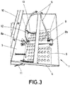
- the filter is distinguished by having, incorporated in the interior of the box and on the interior strainer, a hydraulic piston which is fastened on one end to the lateral door and on the other to the opposite wall of the prismatic body of the box, with this lateral door being attached to the body with an upper hinge that allows it to swing open through the activation of this piston.
- the consequent extension of the piston causes the lateral door to open to give access to the strainer and, once the cleaning operations are done and the door is again closed, this piston exerts force in the opposite direction, keeping the door closed and making its fitting to the body of the box be perfectly watertight and without loss of liquid.
- the interior strainer is linked to the lateral door with a chain, cable or similar which, with the opening of this door, pulls on it and makes it swing on the articulated joint that connects it on one of its sides to the body of the box, so that the activation of the piston, besides automatically opening the lateral door of the filter, at the same time automatically lowers the strainer, so that it hangs vertically to facilitate its cleaning.
- figure number 4 It shows a lateral perspective view of the filter of the invention, in this case represented with the lateral door partially open, noting the way in which the piston moves for its automatic opening.
- the described filter (1) used mainly for its incorporation to a machine (2), for example a tank truck, for applying slurry by means of a spraying system (3) with hydraulic drive, is made from a box consisting of a prismatic body (4), through which the product passes by gravity or pressure, and that has an upper lid (5) for closing it, with an interior strainer (6), composed of a perforated metallic plate, which is placed horizontally to retain the solid contents in the product when it passes through it, and with a lateral door (7) for access to the interior strainer (6) for the extraction and cleaning of the strainer, being distinguished by having means for the automatic opening and closing of this lateral door (7) that, preferably, are constituted by at least one hydraulic piston (8) activated by the hydraulic system of the machine (2) to which it is linked by means of the corresponding hoses (9).
- the hydraulic piston (8) is fastened at one end (8a) to the internal face of the lateral door (7) and at the other end (8b) to the opposite wall of the prismatic body (4) of the box, with this lateral door (7) being joined to the prismatic body (4) by an upper hinge (10) that allows it to swing open, in such a way that by activating the hydraulic piston (8) and its consequent extension, it causes the door to open, giving access to the interior strainer (6) and, when at rest, this piston (8) exerts force in the opposite direction keeping the door (7) closed. None the less, optionally, the lateral door (7) incorporates additional closures, for example, some pressure locking clips (11).
- the interior strainer (6) is connected to the prismatic body (4) of the box of the filter (1) through an articulated connection (12) and is linked to the lateral door (7) with a chain (13), cable or similar such that the opening of this door (7) by means of the activation of the piston (8), at the same time, brings about the automatic lowering of the strainer (6), so that it hangs vertically to facilitate its cleaning.
Landscapes
- Engineering & Computer Science (AREA)
- Life Sciences & Earth Sciences (AREA)
- Water Supply & Treatment (AREA)
- Mechanical Engineering (AREA)
- Hydrology & Water Resources (AREA)
- Environmental & Geological Engineering (AREA)
- Chemical & Material Sciences (AREA)
- Organic Chemistry (AREA)
- Soil Sciences (AREA)
- Environmental Sciences (AREA)
- Filtration Of Liquid (AREA)
Applications Claiming Priority (1)
| Application Number | Priority Date | Filing Date | Title |
|---|---|---|---|
| ES201831903U ES1223301Y (es) | 2018-12-12 | 2018-12-12 | Filtro automatico para purin |
Publications (1)
| Publication Number | Publication Date |
|---|---|
| EP3666054A1 true EP3666054A1 (de) | 2020-06-17 |
Family
ID=65009865
Family Applications (1)
| Application Number | Title | Priority Date | Filing Date |
|---|---|---|---|
| EP19212403.0A Withdrawn EP3666054A1 (de) | 2018-12-12 | 2019-11-29 | Automatischer schleierfilter |
Country Status (2)
| Country | Link |
|---|---|
| EP (1) | EP3666054A1 (de) |
| ES (1) | ES1223301Y (de) |
Cited By (1)
| Publication number | Priority date | Publication date | Assignee | Title |
|---|---|---|---|---|
| CN114452697A (zh) * | 2021-12-20 | 2022-05-10 | 淮北矿业股份有限公司 | 一种巷道注浆加固水泥基浆液杂质自动化过滤装置 |
Citations (5)
| Publication number | Priority date | Publication date | Assignee | Title |
|---|---|---|---|---|
| EP0322941A2 (de) * | 1987-12-02 | 1989-07-05 | Vredo Dodewaard B.V. | Injektionsvorrichtung für Flüssigmist |
| US5833851A (en) * | 1996-11-07 | 1998-11-10 | Adams; Joseph L. | Method and apparatus for separating and deliquifying liquid slurries |
| NL1011139C2 (nl) * | 1999-01-26 | 2001-03-06 | Gerrit Ten Kate | Werkwijze en inrichting voor het scheiden van mest. |
| DE202018004318U1 (de) * | 2018-09-18 | 2018-11-21 | Helmut Mößmer | Kombinierte Separator- und Verteilvorrichtung für Gülle, Gärreste und Ähnliches |
| CN108970207A (zh) * | 2018-06-12 | 2018-12-11 | 贾文玉 | 一种畜牧养殖用粪便清理及回收装置 |
-
2018
- 2018-12-12 ES ES201831903U patent/ES1223301Y/es not_active Expired - Fee Related
-
2019
- 2019-11-29 EP EP19212403.0A patent/EP3666054A1/de not_active Withdrawn
Patent Citations (5)
| Publication number | Priority date | Publication date | Assignee | Title |
|---|---|---|---|---|
| EP0322941A2 (de) * | 1987-12-02 | 1989-07-05 | Vredo Dodewaard B.V. | Injektionsvorrichtung für Flüssigmist |
| US5833851A (en) * | 1996-11-07 | 1998-11-10 | Adams; Joseph L. | Method and apparatus for separating and deliquifying liquid slurries |
| NL1011139C2 (nl) * | 1999-01-26 | 2001-03-06 | Gerrit Ten Kate | Werkwijze en inrichting voor het scheiden van mest. |
| CN108970207A (zh) * | 2018-06-12 | 2018-12-11 | 贾文玉 | 一种畜牧养殖用粪便清理及回收装置 |
| DE202018004318U1 (de) * | 2018-09-18 | 2018-11-21 | Helmut Mößmer | Kombinierte Separator- und Verteilvorrichtung für Gülle, Gärreste und Ähnliches |
Non-Patent Citations (1)
| Title |
|---|
| MAQUINARIA AGRÍCOLA PLUMED S.L.: "APLICADOR DE PURIN MAQUINARIA AGRÍCOLA PLUMED S.L.", 22 March 2018 (2018-03-22), pages 1, XP054980361, Retrieved from the Internet <URL:https://www.youtube.com/watch?v=99-JGMY_vrA> [retrieved on 20200402] * |
Cited By (1)
| Publication number | Priority date | Publication date | Assignee | Title |
|---|---|---|---|---|
| CN114452697A (zh) * | 2021-12-20 | 2022-05-10 | 淮北矿业股份有限公司 | 一种巷道注浆加固水泥基浆液杂质自动化过滤装置 |
Also Published As
| Publication number | Publication date |
|---|---|
| ES1223301U (es) | 2019-01-18 |
| ES1223301Y (es) | 2019-04-10 |
Similar Documents
| Publication | Publication Date | Title |
|---|---|---|
| US5707535A (en) | Vacuum loadable divided phase separator for liquid/solid separation | |
| US5589081A (en) | Divided phase separator for liquid/solid seperation in sludge | |
| US11780757B2 (en) | Apparatus and methods for dewatering sludge | |
| KR102036528B1 (ko) | 침출수 유출 방지형 적재함 | |
| DE102010021239A1 (de) | Mobile Reinigungsanlage für Abfallbehälter | |
| EP2847056B1 (de) | Schienenfahrzeug mit einem innen liegenden tank | |
| CN211536772U (zh) | 一种高效污油过滤机构 | |
| CN110013704A (zh) | 一种固井水罐可清理式过滤装置 | |
| DE202020102850U1 (de) | Trennschacht zur Ableitung von einlaufenden Flüssigkeiten in mindestens zwei Abwasservorrichtungen | |
| EP0434078B1 (de) | Leichtflüssigkeitsabscheider | |
| DE102010010352A1 (de) | Gesteuertes Auftriebsverhalten von in Trinkbehältern befindlichen Elementen | |
| CN209039091U (zh) | 污水处理装置 | |
| EP1243351B1 (de) | Reinigungssystem und Verfahren zur Reinigung von Heizöl | |
| EP1212247A1 (de) | Waschfahrzeug für abfallsammelbehälter | |
| CN220727491U (zh) | 泥浆管路分配器装置 | |
| NO320339B1 (no) | Tank til lagring av flytende produkter | |
| AT502183B1 (de) | Betankungsvorrichtung | |
| CN211051009U (zh) | 一种环境工程固液分离装置 | |
| CN209038341U (zh) | 一种方便实用的垃圾车 | |
| CN109052520A (zh) | 污水处理装置 | |
| EP0333127B1 (de) | Sammel- und Transporttank | |
| JP5840553B2 (ja) | タンクの沈殿汚泥の除去装置 | |
| CN206426904U (zh) | 一种自卸货车 | |
| DE2322378C3 (de) | Klärbehälter | |
| DE1455770C (de) | Flussigkeitstank fur Fahrzeuge |
Legal Events
| Date | Code | Title | Description |
|---|---|---|---|
| PUAI | Public reference made under article 153(3) epc to a published international application that has entered the european phase |
Free format text: ORIGINAL CODE: 0009012 |
|
| STAA | Information on the status of an ep patent application or granted ep patent |
Free format text: STATUS: THE APPLICATION HAS BEEN PUBLISHED |
|
| AK | Designated contracting states |
Kind code of ref document: A1 Designated state(s): AL AT BE BG CH CY CZ DE DK EE ES FI FR GB GR HR HU IE IS IT LI LT LU LV MC MK MT NL NO PL PT RO RS SE SI SK SM TR |
|
| AX | Request for extension of the european patent |
Extension state: BA ME |
|
| RBV | Designated contracting states (corrected) |
Designated state(s): AL AT BE BG CH CY CZ DE DK EE ES FI FR GB GR HR HU IE IS IT LI LT LU LV MC MK MT NL NO PL PT RO RS SE SI SK SM TR |
|
| STAA | Information on the status of an ep patent application or granted ep patent |
Free format text: STATUS: REQUEST FOR EXAMINATION WAS MADE |
|
| 17P | Request for examination filed |
Effective date: 20201218 |
|
| STAA | Information on the status of an ep patent application or granted ep patent |
Free format text: STATUS: EXAMINATION IS IN PROGRESS |
|
| 17Q | First examination report despatched |
Effective date: 20210712 |
|
| STAA | Information on the status of an ep patent application or granted ep patent |
Free format text: STATUS: THE APPLICATION IS DEEMED TO BE WITHDRAWN |
|
| 18D | Application deemed to be withdrawn |
Effective date: 20211123 |