EP3666063B1 - Materialreduktionsmaschine mit antriebsstrangschutzsystem - Google Patents
Materialreduktionsmaschine mit antriebsstrangschutzsystem Download PDFInfo
- Publication number
- EP3666063B1 EP3666063B1 EP19215194.2A EP19215194A EP3666063B1 EP 3666063 B1 EP3666063 B1 EP 3666063B1 EP 19215194 A EP19215194 A EP 19215194A EP 3666063 B1 EP3666063 B1 EP 3666063B1
- Authority
- EP
- European Patent Office
- Prior art keywords
- engine
- material reduction
- speed
- threshold
- operator
- Prior art date
- Legal status (The legal status is an assumption and is not a legal conclusion. Google has not performed a legal analysis and makes no representation as to the accuracy of the status listed.)
- Active
Links
Images




Classifications
-
- F—MECHANICAL ENGINEERING; LIGHTING; HEATING; WEAPONS; BLASTING
- F16—ENGINEERING ELEMENTS AND UNITS; GENERAL MEASURES FOR PRODUCING AND MAINTAINING EFFECTIVE FUNCTIONING OF MACHINES OR INSTALLATIONS; THERMAL INSULATION IN GENERAL
- F16D—COUPLINGS FOR TRANSMITTING ROTATION; CLUTCHES; BRAKES
- F16D48/00—External control of clutches
- F16D48/06—Control by electric or electronic means, e.g. of fluid pressure
-
- A—HUMAN NECESSITIES
- A01—AGRICULTURE; FORESTRY; ANIMAL HUSBANDRY; HUNTING; TRAPPING; FISHING
- A01G—HORTICULTURE; CULTIVATION OF VEGETABLES, FLOWERS, RICE, FRUIT, VINES, HOPS OR SEAWEED; FORESTRY; WATERING
- A01G23/00—Forestry
- A01G23/02—Transplanting, uprooting, felling or delimbing trees
- A01G23/06—Uprooting or pulling up trees; Extracting or eliminating stumps
- A01G23/067—Uprooting or pulling up trees; Extracting or eliminating stumps by comminuting the tree stumps
-
- B—PERFORMING OPERATIONS; TRANSPORTING
- B02—CRUSHING, PULVERISING, OR DISINTEGRATING; PREPARATORY TREATMENT OF GRAIN FOR MILLING
- B02C—CRUSHING, PULVERISING, OR DISINTEGRATING IN GENERAL; MILLING GRAIN
- B02C25/00—Control arrangements specially adapted for crushing or disintegrating
-
- B—PERFORMING OPERATIONS; TRANSPORTING
- B02—CRUSHING, PULVERISING, OR DISINTEGRATING; PREPARATORY TREATMENT OF GRAIN FOR MILLING
- B02C—CRUSHING, PULVERISING, OR DISINTEGRATING IN GENERAL; MILLING GRAIN
- B02C18/00—Disintegrating by knives or other cutting or tearing members which chop material into fragments
- B02C18/06—Disintegrating by knives or other cutting or tearing members which chop material into fragments with rotating knives
- B02C18/16—Details
- B02C18/24—Drives
-
- F—MECHANICAL ENGINEERING; LIGHTING; HEATING; WEAPONS; BLASTING
- F16—ENGINEERING ELEMENTS AND UNITS; GENERAL MEASURES FOR PRODUCING AND MAINTAINING EFFECTIVE FUNCTIONING OF MACHINES OR INSTALLATIONS; THERMAL INSULATION IN GENERAL
- F16D—COUPLINGS FOR TRANSMITTING ROTATION; CLUTCHES; BRAKES
- F16D2500/00—External control of clutches by electric or electronic means
- F16D2500/10—System to be controlled
- F16D2500/104—Clutch
- F16D2500/10406—Clutch position
- F16D2500/10418—Accessory clutch, e.g. cooling fan, air conditioning
-
- F—MECHANICAL ENGINEERING; LIGHTING; HEATING; WEAPONS; BLASTING
- F16—ENGINEERING ELEMENTS AND UNITS; GENERAL MEASURES FOR PRODUCING AND MAINTAINING EFFECTIVE FUNCTIONING OF MACHINES OR INSTALLATIONS; THERMAL INSULATION IN GENERAL
- F16D—COUPLINGS FOR TRANSMITTING ROTATION; CLUTCHES; BRAKES
- F16D2500/00—External control of clutches by electric or electronic means
- F16D2500/10—System to be controlled
- F16D2500/104—Clutch
- F16D2500/10406—Clutch position
- F16D2500/10437—Power Take Off clutch
-
- F—MECHANICAL ENGINEERING; LIGHTING; HEATING; WEAPONS; BLASTING
- F16—ENGINEERING ELEMENTS AND UNITS; GENERAL MEASURES FOR PRODUCING AND MAINTAINING EFFECTIVE FUNCTIONING OF MACHINES OR INSTALLATIONS; THERMAL INSULATION IN GENERAL
- F16D—COUPLINGS FOR TRANSMITTING ROTATION; CLUTCHES; BRAKES
- F16D2500/00—External control of clutches by electric or electronic means
- F16D2500/30—Signal inputs
- F16D2500/306—Signal inputs from the engine
- F16D2500/3067—Speed of the engine
-
- F—MECHANICAL ENGINEERING; LIGHTING; HEATING; WEAPONS; BLASTING
- F16—ENGINEERING ELEMENTS AND UNITS; GENERAL MEASURES FOR PRODUCING AND MAINTAINING EFFECTIVE FUNCTIONING OF MACHINES OR INSTALLATIONS; THERMAL INSULATION IN GENERAL
- F16D—COUPLINGS FOR TRANSMITTING ROTATION; CLUTCHES; BRAKES
- F16D2500/00—External control of clutches by electric or electronic means
- F16D2500/70—Details about the implementation of the control system
- F16D2500/704—Output parameters from the control unit; Target parameters to be controlled
- F16D2500/70422—Clutch parameters
- F16D2500/70424—Outputting a clutch engaged-disengaged signal
Definitions
- the present invention relates to material reduction machines, and more particularly to a drivetrain protection system for material reduction machines.
- Material reduction machines such as stump cutter machines are well known. These machines commonly include a rotating cutter wheel driven by a prime mover (e.g., a gas or diesel engine).
- a prime mover e.g., a gas or diesel engine.
- the cutter wheel while rotating, is advanced toward the stump and moved laterally across the face of the stump. Often, the cutter wheel is automatically advanced across the face of the stump in a sweeping motion.
- the cutter wheel is mounted to one end of a boom which is, in turn, pivotally mounted on a support frame. Hydraulic boom swing cylinders are used to pivot the boom about the pivot point to move the cutter wheel back and forth across the face of the stump to cut it away.
- the handles may also provide additional functions, including determining the presence of the operator.
- the operator station of a stump cutter machine often includes hydraulic control levers that are operated by the operator and other switches/controls. During operation, the entire machine is advanced gradually into the stump, which may require the operator to alter his/her standing position to remain comfortably in front of the controls.
- the engine is operably connected to the cutter wheel by belts that facilitate rotation of the cutter wheel. These belts may fail due to aggressive cutting in which the cutter wheel and/or the engine are overloaded (e.g., when attempting to remove a significant portion of the stump being cut). More specifically, aggressive use of the stump cutter machine may cause the drive belt may break due to an increased load on the belt.
- US 7 011 124 B1 discloses a reversing automatic feed assembly for a stump grinder includes at least one sensor adapted to sense excessive load placed on the stump grinder and output a signal thereof. The reversing automatic feed assembly also includes a control system operatively connected to the least one sensor to automatically reverse feed movement of the cutting assembly in response to the signal from the at least one sensor.
- the invention provides a material reduction machine including an engine, and a material reduction tool.
- a drivetrain includes a coupling and a power transfer element coupled to and driven by the engine when the coupling is in an engaged state, the engaged state configured to transfer power from the engine through the power transfer element for driving the material reduction tool.
- the coupling further has a disengaged state configured to inhibit transfer of power from the engine through the power transfer element.
- a control system includes a sensor, a drivetrain protection system, and a controller.
- the sensor is in communication with the engine or the material reduction tool to detect a speed of the engine or the material reduction tool.
- the drivetrain protection system is selectively operable during operation of the material reduction tool and, when triggered, configured to protect the power transfer element by putting the coupling into the disengaged state.
- the controller includes instructions configured to enable the drivetrain protection system in response to a first signal from the sensor indicative of the speed at or above a first threshold, the controller further including instructions to trigger the drivetrain protection system in response to a second signal from the sensor indicative of the speed below a second threshold.
- a drivetrain includes a coupling and a belt coupled to and driven by the engine when the coupling is in an engaged state, the engaged state configured to transfer power from the engine through the belt for driving the material reduction tool.
- the coupling further has a disengaged state configured to inhibit transfer of power from the engine through the belt.
- a control system includes a sensor, a drivetrain protection system, and a controller. The sensor is in communication with the engine to detect a speed of the engine.
- the drivetrain protection system is selectively operable during operation of the material reduction tool and, when triggered, configured to protect the belt by putting the coupling into the disengaged state.
- the controller includes instructions configured to enable the drivetrain protection system in response to a first signal from the sensor indicative of the speed at or above a first threshold, the controller further including instructions to trigger the drivetrain protection system in response to a second signal from the sensor indicative of the speed below a second threshold.
- the invention provides a method of controlling a material reduction machine including an engine and a material reduction tool.
- a drivetrain including a power transfer element positioned between the engine and the material reduction tool and a coupling having an engaged state configured to enable transfer of power from the engine through the power transfer element for driving the material reduction tool, the coupling further having a disengaged state configured to inhibit transfer of power from the engine through the power transfer element.
- the engine is run at an engine speed, and a rotational speed is imparted to the material reduction tool by transferring power from the engine to the material reduction tool via the drivetrain, including the power transfer element, with the coupling is in the engaged state.
- a sensor senses one or both of the engine speed and the rotation speed of the material reduction tool and reports signals to a controller of a control system.
- a drivetrain protection system is enabled in response to a first signal from the sensor reporting the sensed engine speed or rotation speed at or above a first threshold.
- the drivetrain protection system is triggered to protect the power transfer element by putting the coupling into the disengaged state in response to a second signal from the sensor reporting the sensed engine speed or rotation speed below a second threshold.
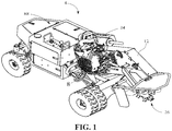
- Figs. 1 and 2 illustrate an exemplary material reduction or stump cutter machine 4 embodying the present invention.
- the stump cutter machine 4 includes a frame 8 that has a movable boom 12 pivotally attached to the frame 8 about a horizontal axis (defined through a pin 16). As described in detail below, the boom 12 also is movable in a lateral sweeping motion relative to the frame 8 (e.g., automatic sweep). Wheels 20 are rotatably attached to the frame 8 via an axle to enable movement of the stump cutter machine 4. It will be appreciated that the stump cutter machine 4 can move across a surface in other ways (e.g., using tracks in lieu of wheels 20).
- the stump cutter machine 4 also includes a prime mover or engine 24 (e.g., a gasoline or diesel engine, a battery pack, etc.) that is mounted on the boom 12, and a cutter wheel or material reduction tool 26 that is mounted adjacent a distal end of the boom 12.
- a prime mover or engine 24 e.g., a gasoline or diesel engine, a battery pack, etc.
- a cutter wheel or material reduction tool 26 that is mounted adjacent a distal end of the boom 12.
- the terms 'prime mover' and 'engine' are interchangeable and are intended to refer to any appropriate mechanism for driving the cutter wheel 26.
- the engine 24 provides hydraulic fluid to one or more boom lift cylinders 28 and boom swing cylinders 32 (e.g., via one or more pumps 34 driven by the engine 24) to facilitate movement of the boom 12 that, in turn, moves the cutter wheel 26 into and across the face of the stump being cut. More specifically, the boom lift cylinder 28 raises and lowers the boom 12, and the boom swing cylinder 32 oscillates the boom 12 in a lateral arc relative to the frame 8.
- the cutter wheel 26 is operatively coupled to and driven by the engine 24.
- the engine 24 has a crankshaft or output shaft 40 that is coupled to the cutter wheel 26 by a drivetrain 44.
- the drivetrain 44 has a first belt 48, a second belt 52, an electric clutch or coupling 56 to connect the engine 24 to the drivetrain 44, a jackshaft 60, and a brake 62 (e.g., spring brake).
- the illustrated first and second belts 48, 52 are non-limiting examples of power transfer elements of the drivetrain 44, and are tensioned by tension wheels 64, 68.
- Each of the belts 48, 52 is a flexible, endless power transmission belt that couples spaced-apart rotatable components for rotation together at a predetermined speed ratio (e.g., pulley diameter ratio).
- the first belt 48 is coupled to the output shaft 40 by a pulley 72 attached to the output shaft 40 (e.g., selectively through the clutch 56).
- the first belt 48 also is coupled to a pulley 76 that is attached to the jackshaft 60. In this manner, the first belt 48 wraps around the pulleys 72, 76, and is driven by rotation of the output shaft 40.
- the second belt 52 is coupled to the jackshaft 60 by the pulley 76 and to a driveshaft 80 of the cutter wheel 26 by a pulley 84.
- the second belt 52 wraps around the pulleys 76, 84, and is driven by movement of the first belt 48.
- the intermediate pulley 76 is formed in two parts co-rotatable together, with separate parts for the separate belts 48, 52.
- the pulleys 72, 76, 84 disclosed herein may take any suitable form of pulley, sheave, or wheel. It will be appreciated that the cutter wheel 26 can be driven in other ways (e.g., via a hydrostatic system, or driveshafts and gearboxes).
- the coupling for engaging and disengaging the drivetrain 44 can be provided by various types of clutches, or alternately by a hydraulic valve, or by a belt tightener device including an actuator to apply operating tension to one or more drive belts.
- a hydraulic valve or belt-tensioning actuator the coupling engages and disengages power transfer even though there is not a finite attachment/detachment of power transfer structures as with most clutches.
- the clutch 56 is engaged with the output shaft 40 of the engine 24 to drive the cutter wheel 26 through drivetrain 44, and can be automatically disengaged to stop the transfer of power from the engine 24 to the cutter wheel 26.
- the clutch 56 can be any coupling that selectively enables or disables power transfer from a prime mover or engine 24.
- the stump cutter machine 4 includes an operator control station 88 that has levers 92 to control movement of the boom 12 and the cutter wheel 26. As shown, the control station 88 has handles or levers 92 that are used by an operator to position the cutter wheel 26 via movement of the boom 12, although fewer or more levers or controls may be provided. With reference to Figs.
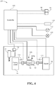
- the levers 92 optionally include sensors 96 (e.g., capacitance sensors) that are part of a control system 100 and that detect the presence of an operator at the operator control station 88.
- the sensors 96 may have an equal or differing predetermined fixed delay period to allow an operator to move between the levers 92. Equal or different delay periods may be employed for each of the sensors 96 (e.g., depending on the last sensor touched by the operator).
- the delay periods may be of variable duration based on operational characteristics of the stump cutter machine 4 (e.g., longer when the cutter wheel 26 is rotating at relatively high speed, and shorter when the speed is relatively low).
- OPS operator presence system
- the signals from the sensors 96 indicating the presence (or absence) of an operator are communicated to a controller 104 of the control system 100 via wires or wirelessly, or some combination of wires and wireless communication.
- the control system 100 also is in communication with other inputs and outputs of the stump cutter machine 4. As shown, the outputs include a clutch relay or solenoid 108, a clutch light 112, and a clutch switch 116.
- An operator can manually engage the clutch 56 by manipulating the clutch switch 116, and the clutch light 112 illuminates to provide a visual indication to an operator regarding the status of the clutch 56.
- the controller 104 de-energizes the clutch relay 108, which automatically disengages the clutch 56 so that the cutter wheel 26 is operatively disengaged from the engine 24 (i.e. the wheel 26 is no longer rotated by the drivetrain 44).
- the brake 62 may be engaged to stop the cutter wheel 26.
- One or more additional diagnostic or status identifiers 120 may be included in the control system 100 to convey useful information to the operator.
- the brake 62 may be separate from or integrated into the clutch 56.
- the controller 104 monitors the speed (i.e., rotational speed) of the engine 24 via an engine speed sensor 124.
- the controller 104 can also or alternately monitor the speed (i.e., rotational speed) of the cutter wheel 26 via a wheel speed sensor 128.
- the engine speed sensor 124 is positioned adjacent the engine 24 and detects rotation of the shaft 40 (not labelled in Fig 4 ), and the wheel speed sensor 128 is positioned adjacent the cutter wheel 26 and detects rotation of the driveshaft 80 (not labelled in Fig 4 ).
- the sensors 124, 128 may be any type of sensors capable of measuring rotations of the engine 24 and the cutter wheel 26, respectively.
- the controller 108 may automatically disengage the clutch 56 and/or move the cutter wheel 26 via the boom 12.
- Engine and/or cutter wheel speed (e.g., in revolutions per minute "RPM") can be determined from the output(s) of the sensor(s) 124, 128 in conjunction with a clock or "timer.”
- timer may be provided within the controller 104 that receives pulse signals from the sensor(s) 124, 128 indicative of rotational movement of the engine 24 and/or the cutter wheel 26.
- cutter wheel speed detected by the wheel speed sensor 128 may be a suitable substitute (or even used in conjunction).
- engine speed detected by the engine speed sensor 124 there is a fixed, known relationship between the engine speed and the cutter wheel speed when the clutch 56 is engaged.
- determination of the engine speed can effectively be made by correlating a speed of the cutter wheel 26 to engine speed for comparing to engine speed thresholds, or the thresholds themselves may be set as cutter wheel speed thresholds.
- the stump cutter machine 4 may include only the engine speed sensor 124, or only the wheel speed sensor 128, and not the other.
- the illustrated stump cutter machine 4 also includes a feature that automatically moves the cutter wheel 26 with respect to the stump being reduced (e.g., to sweep the cutter wheel 26 laterally along the stump).
- An exemplary control is described and illustrated in U.S. Patent No. 6,014,996 (assigned to Vermeer Manufacturing Company). Not essential information for the invention has been deleted (Art. 84 EPC, Guidelines F-III, 8). Features have been previously provided to the marketplace by Vermeer Manufacturing Company, marketed as SmartSweep® or AutoSweep®.
- automatic sweep control moves the cutter wheel 26 (via the boom 12) across the width of a stump at a predetermined rate that is based on the speed of the engine 24.
- the maximum sweep speed of the automatic sweep control is predetermined in the control system or set using a lever on the control panel 88.
- the controller 104 automatically adjusts (i.e., reduces) the sweep speed of the cutter wheel 26 across the stump.
- the automatic sweep speed reduction can be accomplished in some constructions by bleeding hydraulic fluid from the boom swing cylinder 32.
- the engine 24 of the stump cutter machine 4 may have idle (“low idle”) and high idle speeds.
- the idle speed of the engine 24 may be varied by the operator via controls at the control station 88 (low/high selection, or continuously variable between low and high limits).
- Low idle can be a speed from 1000 RPM to 2000 RPM in some constructions
- high idle can be a speed from 3500 RPM to 4500 RPM.
- the low idle speed is 1600 RPM
- the high idle engine speed is 4100 RPM.
- the controller 104 bleeds a portion of the hydraulic fluid flow to the boom swing cylinder 32, which slows movement of the boom 12 and consequently the sweep speed of the cutter wheel 26 across the stump.
- a first predetermined speed e.g., 4000 RPM
- the controller 104 bleeds a portion of the hydraulic fluid flow to the boom swing cylinder 32, which slows movement of the boom 12 and consequently the sweep speed of the cutter wheel 26 across the stump.
- a second predetermined speed e.g., 3300 RPM
- all hydraulic fluid to the boom swing cylinder 32 is bled off by the controller 104.
- the amount of hydraulic fluid that is bled off can be based on the engine speed - more fluid is bled off as the engine speed drops from the first predetermined speed toward the second predetermined speed.
- the controller 104 increases the flow of hydraulic fluid to the boom swing cylinder 32 to reinitiate automatic sweep.
- the sweep movement can restart at the maximum sweep speed, or may increase gradually based on the engine speed as engine speed increases.
- the stump cutter machine 4 further includes a drivetrain protection system (“DPS”) that minimizes or prevents damage to components of the drivetrain 44 (e.g., the belts 48, 52) when the drivetrain 44 experiences a significant increase in cutting load, referred to herein as an overload condition.
- DPS drivetrain protection system
- the drivetrain protection system may default to a disabled condition, and may only be activated to operate during a predetermined running range of the stump cutter machine 4, after an initial start-up process that gets the cutter wheel 26 up to a running speed, or "normal” running. In normal running, the engine 24 runs at a non-zero speed and the cutter wheel 26 rotates at a speed that correlates to the engine speed according to the drivetrain transmission ratio (e.g., determined by pulley diameter ratios).
- a separate start-up protection system or procedure may be carried out to engage the coupling for initially running up the cutter wheel 26 from a stationary condition.
- the engine 24 may be set at or near low idle speed when engaging the clutch 56 (or activating an actuator of a belt tightener to tension the drivetrain 44 into operating tension).
- the control system may only enable the clutch 56 to engage when the engine 24 is at low idle. While the invention is described in detail relative to preventing failure of the belts 48, 52 due an overload condition, it will be appreciated that the drivetrain protection system can protect or prevent damage to other components of the drivetrain 44.
- the drivetrain protection system is part of the same machine control system 100 as the other control features disclosed herein, implemented either within the same physical controller 104 or a separate controller.
- the illustrated drivetrain 44 is a belt-type mechanical drivetrain (e.g., including the belts 48, 52), aspects of the drivetrain protection system are not necessarily limited as such, and the drivetrain protection system may be provided in a stump cutter or other material reduction machine having or including additional or alternative drivetrain components, including but not limited to a hydraulic drive system, or gearbox for example.
- a hydraulic drive system having, for example, a hydraulic pump, a hydraulic motor, hoses, and valves
- the coupling that is selectively disengaged by the drivetrain protection system can be provided as a hydraulic valve that partially or fully interrupts the supply of pressurized hydraulic fluid to the hydraulic motor driving the cutter wheel 26.
- the drivetrain protection system not only automatically disengages the clutch 56 if the engine speed reaches a designated threshold, but will also stop the sweeping movement of the boom 12 if the drivetrain protection system is implemented on a stump cutter machine 4 that includes automatic sweep control. Stopping the sweeping motion of the boom 12 in this situation prevents damage to the cutter wheel 26 and the drivetrain 44.
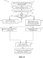
- Figs. 5-8 illustrate different control processes for the stump cutter machine 4 using data from the engine speed sensor 124 and/or the wheel speed sensor 128. Common processes are labeled with the same reference numerals for ease of understanding.
- the controller 104 uses the feedback from the sensors 96, the engine speed sensor 124, and the wheel speed sensor 128 to carry out instructions corresponding to the example methods and stored on the controller 104.
- the drivetrain protection system is initially disabled.
- the drivetrain protection system is enabled, or "activated” in response to determining that the engine speed reaches or exceeds a first threshold or activation threshold (e.g., when the engine speed is at or above 3500 RPM).
- the activation threshold can be above the low idle speed, and can be between the low and high idle speeds.
- engine speed must be ramped up to enable the drivetrain protection system following start-up of the cutter wheel 26 at or near low idle speed, otherwise the drivetrain protection system remains in a disabled state.
- the drivetrain protection system then operates automatically to selectively disengage the clutch 56 to prevent damage to the drivetrain 44 in response to a trigger condition, or "trigger.”
- the trigger can be identification of the engine speed dropping below a second threshold, or “overload threshold” (e.g., 2500 RPM). It should be understood that the activation threshold for enabling the drivetrain protection system is lower than the first predetermined speed at which the automatic sweep control begins bleeding off flow from the boom swing cylinder 32.
- the DPS overload threshold is set at or below the second predetermined speed of the automatic sweep control so that the drivetrain protection system does not interfere with the full range of automatic sweep operation.
- the clutch 56 may be manually re-engaged by the operator: the operator presses the clutch ON switch 96 which provides an input to the controller 104 to engage the clutch 56.
- the drivetrain protection system can work independent of or in conjunction with the operator presence system and/or the automatic sweep control.
- the drivetrain protection system also automatically disengages the clutch 56, after being enabled, if the cutter wheel 26 is slowed manually by the operator to the point where the engine speed is lower than the overload threshold (i.e., the slowing of the cutter wheel 26 is not directly attributable to increased cutting load).
- the drivetrain protection system is only responsive to unintentional slowing, while deliberate operator-directed slowing is disregarded by the drivetrain protection system.
- the drivetrain protection system before enacting the DPS clutch disengagement, can take into consideration the operator throttle control setting on the stump cutter machine 4 to determine whether the reduced speed of the cutter wheel 26 and corresponding engine speed is attributable to cutting load from the stump, or simply operator-directed.
- Fig. 5 is an exemplary flowchart illustrating a control process 130 that is implemented by the control system 100 for the stump cutter machine 4 including the drivetrain protection system and the operator presence system (with or without automatic sweep control).
- the controller 104 determines that the engine 24 is running and that the clutch 56 is disengaged (meaning the clutch indicator light 112 is off).
- the controller 104 verifies that the operator is present based on contact with one or more of the levers 92.
- the clutch 56 is engaged by manipulating the clutch switch 116, which turns on the clutch indicator light 112. Step 140 should only occur with the engine at idle, in order to avoid damage to the clutch 56.
- the operator increases the engine speed from idle to operating speed.
- the controller 104 determines at block 144 whether the engine speed is at or above the DPS activation threshold.
- the control system 100 determines that the engine speed is at or above the DPS activation threshold ("Yes" at block 144), indicating that the operator has increased the engine speed from idle to operating speed, the drivetrain protection system is activated and the control system 100 begins to monitor the engine speed, via the engine speed sensor 124, at block 148 (referred to as "DPS operation") to determine whether the engine speed drops below the DPS overload threshold.
- DPS operation the control system 100 determines whether the operator is present (i.e. not absent for a predefined delay period) via the operator presence system. With the operator present, the drivetrain protection system determines that the engine speed is less than the DPS overload threshold at block 152.
- the drivetrain protection system automatically disengages the clutch 56, by a signal output from the controller 104.
- the drivetrain protection system engages the brake 62 to affirmatively stop the cutter wheel 26.
- the engine 24 remains running and the clutch light 112 is turned off to indicate to the operator that the clutch 56 is disengaged (block 160).
- the operator presence system determines whether the operator has been absent for a time that equals or exceeds the delay period (block 164), which may account for cutter wheel deceleration time. If not, the system returns to idle operation. If so, the system automatically disengages the clutch 56. In some instances, the system engages the brake 62 to affirmatively stop the cutter wheel 26. After the clutch 56 has been disengaged, the engine speed recovers and the engine 24 continues to run, and the clutch light 112 is turned off to indicate to the operator that the clutch is disengaged (block 160).
- control system 100 determines that the engine speed is less than the activation threshold ("No" at block 144), the control system 100 continues "idle operation" of the stump cutter machine 4 with the engine 24 at or near low idle speed (i.e. the engine speed is lower than the activation threshold) with the clutch 56 engaged (block 176). Thereafter, the control system 112 begins to monitor for the presence of the operator. If the operator presence system determines that the operator is present, the control process 130 returns to block 144. Otherwise the control process 130 moves to block 164 and the system 114 functions according to the determinations and steps taken with regard to blocks 164, 172, 160 (in order) as described above.
- Fig. 6 is another exemplary flowchart illustrating a control process 178 that can be implemented by the control system 100 for the stump cutter machine 4 including the drivetrain protection system, the operator presence system, and the automatic sweep control.
- the drivetrain protection system and the operator presence system are the same as described with regard to Fig. 5 .
- the controller 104 determines that the engine 24 is running and that the clutch 56 is disengaged (meaning the clutch indicator light 112 is off).
- the controller 104 verifies that the operator is present based on contact with one or more of the levers 92.
- the clutch 56 is engaged by manipulating the clutch switch 116, which turns on the clutch indicator light 112.
- the controller 104 determines at block 144 whether the engine speed is above the activation threshold.
- the drivetrain protection system is activated and the control system 100 begins to monitor the engine speed to determine whether the engine speed reaches or drops below the overload threshold at block 148 (DPS operation).
- the control system 100 determines whether the operator is present (i.e. not absent for a predefined delay period) via the operator presence system. With the operator present, the drivetrain protection system determines that the engine speed is less than the overload threshold at block 152. As a result, the drivetrain protection system automatically disengages the clutch 56. In some instances, the drivetrain protection system engages the brake 62 to affirmatively stop the cutter wheel 26. After the clutch 56 has been disengaged, the engine 24 remains running and the clutch light 112 is turned off to indicate to the operator that the clutch is disengaged (block 188).
- the operator presence system determines whether the operator has been absent for a time that equals or exceeds the delay period (block 164). If so, the system automatically disengages the clutch 56. In some instances, the system engages the brake 62 to affirmatively stop the cutter wheel 26. After the clutch 56 has been disengaged, the engine speed recovers and the engine 24 continues to run, and the clutch light 112 is turned off to indicate to the operator that the clutch is disengaged (block 188).
- control system 100 determines that the engine speed is less than the activation threshold ("No" at block 144)
- the control system 100 operates the stump cutter machine 4 with the engine 24 at an idle speed (i.e. the engine speed is lower than the activation threshold) with the clutch 56 engaged and the clutch light 112 flashing (block 176).
- the control system 112 begins to monitor for the presence of the operator. If the operator presence system determines that the operator is present, the control process 178 returns to block 144. Otherwise the control process 178 moves to block 164 and the system 114 functions according to the determinations and steps taken with regard to blocks 164, 172, 188 (in order) as described above.
- the automatic sweep control is implemented after or when the operator actuates the clutch switch 116 regardless of whether the drivetrain protection system is activated.
- the engine speed sensor 124 monitors the engine speed.
- the speed of the cutter wheel 26 across the stump is changed based on the engine speed. If the engine speed is at or above 4000 RPM, the speed of the cutter wheel 26 moving across the stump is not reduced. If the engine speed is 3000 or less, the speed of the cutter wheel 26 moving across the stump is fully stopped until the engine speed increases again. In this example, for an engine speed between 3000 and 4000 RPM, the lateral moving speed of the cutter wheel 26 across the stump is an intermediate speed between full speed and stationary.
- the automatic sweep control runs simultaneously with the drivetrain protection system operation and the operator absence presence system. If the clutch 56 is disengaged for any reason, the engine 24 continues running and the automatic sweep operation is turned off (block 188).
- Fig. 7 depicts another exemplary control process 192 that is implemented by the control system 100 for the stump cutter machine 4 including only the drivetrain protection system (i.e. without the operator presence system and the automatic sweep control).
- the steps in this control process mirror the blocks described with regard to the drivetrain protection system of Fig. 5 . More specifically, at block 132, the controller 104 determines that the engine 24 is running and that the clutch 56 is disengaged (meaning the clutch indicator light 112 is off). At block 140, the clutch 56 is engaged by manipulating the clutch switch 116, which turns on the clutch indicator light 112. The controller 104 determines at block 144 whether the engine speed is above the activation threshold.
- the drivetrain protection system is activated and the control system 100 begins to monitor the engine speed to determine whether the engine speed reaches or drops below the overload threshold at block 148 (DPS operation).
- the control system 100 determines whether the operator is present (i.e. not absent for a predefined delay period) via the operator presence system. With the operator present, the drivetrain protection system determines that the engine speed is less than the overload threshold at block 152. As a result, the drivetrain protection system automatically disengages the clutch 56. In some instances, the drivetrain protection system engages the brake 62 to affirmatively stop the cutter wheel 26. After the clutch 56 has been disengaged, the engine 24 remains running and the clutch light 112 is turned off to indicate to the operator that the clutch is disengaged (block 160).
- the stump cutter machine 4 is in idle operation with the clutch 56 engaged and the clutch indicator light 100 flashing (block 176). The stump cutter machine 4 remains in idle operation until the engine speed reaches the activation threshold.
- Fig. 8 illustrates another exemplary control process 194 that is implemented by the control system 100 for the stump cutter machine 4 including the drivetrain protection system and a portion of the operator presence system.
- the control process 194 does not include automatic sweep control.
- the controller 104 determines that the engine 24 is running and that the clutch 56 is disengaged (meaning the clutch indicator light 112 is off).
- the controller 104 verifies that the operator is present based on contact with one or more of the levers 92.
- the clutch 56 is engaged by manipulating the clutch switch 116, which turns on the clutch indicator light 112.
- the controller 104 determines at block 144 whether the engine speed is above the activation threshold.
- the drivetrain protection system is activated and the control system 100 begins to monitor the engine speed to determine whether the engine speed reaches or drops below the overload threshold at block 148 (DPS operation).
- the control system 100 determines whether the operator is present (i.e. not absent for a predefined delay period) via the operator presence system. With the operator present, the drivetrain protection system determines that the engine speed is less than the overload threshold at block 152. As a result, the drivetrain protection system automatically disengages the clutch 56. In some instances, the drivetrain protection system engages the brake 62 to affirmatively stop the cutter wheel 26. After the clutch 56 has been disengaged, the engine 24 remains running and the clutch light 112 is turned off to indicate to the operator that the clutch is disengaged (block 160).
- the drivetrain protection system operational after block 148, and when the operator presence system determines if the operator has been absent for a time that equals or exceeds the delay period (block 164). If so, the system automatically disengages the clutch 56. In some instances, the system engages the brake 62 to affirmatively stop the cutter wheel 26. After the clutch 56 has been disengaged, the engine 24 continues to run, and the clutch light 112 is turned off to indicate to the operator that the clutch is disengaged (block 160).
- control system 100 determines that the engine speed is less than the activation threshold ("No" at block 144)
- the control system 100 operates the stump cutter machine 4 with the engine 24 at an idle speed (i.e. the engine speed is lower than the activation threshold) with the clutch 56 engaged and the clutch light 112 flashing (block 176).
- the control system 112 begins to monitor for the presence of the operator. If the operator presence system determines that the operator is present (i.e. the delay period has not elapsed), the control process 178 returns to block 144. Otherwise, the control process 194 moves to block 164 and the system 100 functions according to the determinations and steps taken with regard to blocks 164, 156, and 160 (in order) as described above.
- the operator positions the stump cutter wheel 26 at one edge of the stump so that the stump cutter wheel 26 moves across the width of the stump.
- higher loads may be placed on the cutter wheel 26 due to, for example, knots in the stump.
- the drivetrain protection system operates to disengage power transfer from the engine 24 to the cutter wheel 26 based on a threshold speed that corresponds to a load on the cutter wheel 26 that less than what is expected to cause damage to the belts 48, 52 or another power transfer element of the drivetrain.
- the drivetrain protection system reduces downtime of the stump cutter machine 4 by reducing the need for maintenance or part replacement.
- the drivetrain protection system can work in conjunction with the operator presence system and/or the automatic sweep system, in order to provide an integrated control process for controlling operation of the stump cutter machine 4.
Landscapes
- Life Sciences & Earth Sciences (AREA)
- Engineering & Computer Science (AREA)
- General Engineering & Computer Science (AREA)
- Biodiversity & Conservation Biology (AREA)
- Ecology (AREA)
- Forests & Forestry (AREA)
- Environmental Sciences (AREA)
- Physics & Mathematics (AREA)
- Fluid Mechanics (AREA)
- Mechanical Engineering (AREA)
- Food Science & Technology (AREA)
- Harvester Elements (AREA)
Claims (15)
- Materialreduktionsmaschine (4), umfassend:einen Motor (24);ein Materialreduktionswerkzeug (26);einen Antriebsstrang (44), der eine Kopplung (56) und ein Leistungsübertragungselement (48, 52) beinhaltet, das an den Motor (24) gekoppelt ist und von diesem angetrieben wird, wenn die Kopplung (56) in einem Eingriffszustand ist, wobei der Eingriffszustand ausgebildet ist, Übertragung von Leistung von dem Motor (24) durch das Leistungsübertragungselement (48, 52) zum Antreiben des Materialreduktionswerkzeugs (26) zu ermöglichen, wobei die Kopplung (56) weiter einen gelösten Zustand aufweist, der ausgebildet ist, Übertragung von Leistung von dem Motor (24) durch das Leistungsübertragungselement (48, 52) zu unterbinden; undein Steuersystem (100) beinhaltendeinen Sensor (96) in Kommunikation mit dem Motor (24) oder dem Materialreduktionswerkzeug (26), um eine Geschwindigkeit des Motors (24) oder des Materialreduktionswerkzeugs (26) zu erfassen, gekennzeichnet durchein Antriebsstrangschutzsystem, das selektiv während Betriebs des Materialreduktionswerkzeugs (26) betreibbar ist und, wenn ausgelöst, ausgebildet ist, das Leistungsübertragungselement (48, 52) zu schützen, indem die Kopplung (56) in den gelösten Zustand gesetzt wird, undeine Steuerung (104), die Anweisungen beinhaltet, die ausgebildet sind, das Antriebsstrangschutzsystem als Reaktion auf ein erstes Signal von dem Sensor (96) freizugeben, das die Geschwindigkeit bei oder über einem ersten Schwellenwert anzeigt, wobei die Steuerung (104) weiter Anweisungen beinhaltet, um das Antriebsstrangschutzsystem als Reaktion auf ein zweites Signal von dem Sensor (96) freizugeben, das die Geschwindigkeit unter einem zweiten Schwellenwert anzeigt.
- Materialreduktionsmaschine nach Anspruch 1, wobei der zweite Schwellenwert niedriger als der erste Schwellenwert ist.
- Materialreduktionsmaschine nach Anspruch 1 oder 2, wobei der Motor (24) durch Bedienersteuerung zwischen einer niederen Leerlaufdrehzahl und einer hohen Leerlaufdrehzahl variabel ist und wobei beide, der erste Schwellenwert und der zweite Schwellenwert Motorgeschwindigkeiten zwischen der niederen Leerlaufdrehzahl und der hohen Leerlaufdrehzahl entsprechen.
- Materialreduktionsmaschine nach einem der vorstehenden Ansprüche, wobei der Motor (24) durch Bedienersteuerung zwischen einer niederen Leerlaufdrehzahl und einer hohen Leerlaufdrehzahl variabel ist und wobei der erste Schwellenwert einer Motorgeschwindigkeit über der niederen Leerlaufdrehzahl entspricht.
- Materialreduktionsmaschine nach einem der vorstehenden Ansprüche, wobei die Kopplung (56) eine Kupplung beinhaltet.
- Materialreduktionsmaschine nach einem der vorstehenden Ansprüche, wobei das Leistungsübertragungselement (48, 52) einen Riemen beinhaltet, der um erste und zweite Riemenscheiben gewickelt ist.
- Materialreduktionsmaschine nach einem der vorstehenden Ansprüche, wobei das Steuersystem (100) weiter eine automatische Steuerung umfasst, die betreibbar ist, um das Materialreduktionswerkzeug (26) bei einer vorbestimmten Bewegungsgeschwindigkeit entlang des zu reduzierenden Materials zu bewegen, wobei die vorbestimmte Bewegungsgeschwindigkeit auf der Geschwindigkeit des Motors (24) oder des Materialreduktionswerkzeugs (26) beruht, und wobei die automatische Steuerung ausgebildet ist, die Bewegungsgeschwindigkeit des Materialreduktionswerkzeugs (26) von der vorbestimmten Bewegungsgeschwindigkeit als Reaktion darauf zu verringern, dass erfasst wird, dass die Geschwindigkeit des Motors (24) oder des Materialreduktionswerkzeugs (26) bei oder unter einem dritten Schwellenwert ist, und wobei die automatische Steuerung vorzugsweise betreibbar ist, um Bewegung des Materialreduktionswerkzeugs (26) entlang des zu reduzierenden Materials als Reaktion darauf zu stoppen, dass erfasst wird, dass die Geschwindigkeit des Motors (24) oder des Materialreduktionswerkzeugs (26) bei oder unter einem vierten Schwellenwert ist, wobei der zweite Schwellenwert bei oder unter dem vierten Schwellenwert eingestellt ist.
- Materialreduktionsmaschine nach Anspruch 7, wobei die Materialreduktionsmaschine eine Baumstumpffräse (4) ist und das Materialreduktionswerkzeug (26) ein Baumstumpffräsrad ist und die automatische Steuerung betreibbar ist, das Baumstumpffräsrad seitlich über einen Baumstumpf zu bewegen.
- Materialreduktionsmaschine nach einem der vorstehenden Ansprüche, wobei das Steuersystem (100) weiter ein Bedieneranwesenheitssystem umfasst, das ausgebildet ist, eine Anwesenheit eines Bedieners in unmittelbarer Nähe oder in Berührung mit der Materialreduktionsmaschine zu erfassen, und wobei die Steuerung (104) weiter Anweisungen beinhaltet, um die Kopplung (56) als Reaktion auf eine Bestimmung durch das Bedieneranwesenheitssystem, dass der Bediener nicht anwesend ist, in den gelösten Zustand zu bringen.
- Materialreduktionsmaschine nach einem der vorstehenden Ansprüche, weiter umfassend eine Bremse, die positioniert und angeordnet ist, um Drehung des Materialreduktionswerkzeugs (26) zu stoppen, wenn die Kopplung (56) in dem gelösten Zustand ist.
- Verfahren zum Steuern einer Materialreduktionsmaschine, die einen Motor (24) und ein Materialreduktionswerkzeug (26) beinhaltet, wobei das Verfahren umfasst:Bereitstellen eines Antriebsstrangs (44), der ein Leistungsübertragungselement (48, 52) beinhaltet, das zwischen dem Motor (24) und dem Materialreduktionswerkzeug (26) positioniert ist, und eine Kopplung (56), die einen Eingriffszustand aufweist, der ausgebildet ist, Übertragung von Leistung von dem Motor (24) durch das Leistungsübertragungselement (48, 52) zum Antreiben des Materialreduktionswerkzeugs (26) zu ermöglichen, wobei die Kopplung (56) weiter einen gelösten Zustand aufweist, der ausgebildet ist, Übertragung von Leistung von dem Motor (24) durch das Leistungsübertragungselement (48, 52) zu unterbinden;Betreiben des Motors (24) bei einer Motorgeschwindigkeit;Verleihen einer Drehzahl dem Materialreduktionswerkzeug (26) durch Übertragen von Leistung von dem Motor (24) zu dem Materialreduktionswerkzeug (26) über den Antriebsstrang (44), das Leistungsübertragungselement (48, 52) beinhaltend, während die Kopplung (56) im Eingriffszustand ist;Erfassen, mit einem Sensor (96), eines oder beider der Motorgeschwindigkeit und der Drehzahl des Materialreduktionswerkzeugs (26); wobei das Verfahren durch die folgenden Schritte gekennzeichnet istFreigeben, durch eine Steuerung (104), eines Antriebsstrangschutzsystems, als Reaktion darauf, dass die Motorgeschwindigkeit oder Drehzahl einen ersten Schwellenwert erreicht; undAuslösen, durch die Steuerung (104), des Antriebsstrangschutzsystems, um das Leistungsübertragungselement (48, 52) zu schützen, indem die Kopplung (56) als Reaktion darauf, dass die Motorgeschwindigkeit oder Drehzahl unter einen zweiten Schwellenwert fällt, automatisch in den gelösten Zustand versetzt wird.
- Verfahren nach Anspruch 11, wobei der zweite Schwellenwert niedriger als der ersten Schwellenwert ist, wobei das Verfahren Erhöhen von Motorgeschwindigkeit umfasst, während die Kopplung (56) im Eingriffszustand ist, um den zweiten Schwellenwert zu übersteigen und anschließend den ersten Schwellenwert zu übersteigen, um das Antriebsstrangschutzsystem freizugeben.
- Verfahren nach Anspruch 11 oder 12, weiter umfassend automatisches Bewegen des Materialreduktionswerkzeugs (26) bei einer vorbestimmten Geschwindigkeit seitlich über zu reduzierendes Material, wobei die vorbestimmte Geschwindigkeit auf der Geschwindigkeit des Motors (24) oder des Materialreduktionswerkzeugs (26) beruht, und das Verfahren weiter umfasst, die seitliche Bewegung des Materialreduktionswerkzeugs (26) automatisch zu verlangsamen, wenn die Geschwindigkeit des Motors (24) oder des Materialreduktionswerkzeugs (26) abnimmt, um einen dritten Schwellenwert zu erreichen, der über dem zweiten Schwellenwert eingestellt ist.
- Verfahren nach Anspruch 13, weiter umfassend automatisches Stoppen der seitlichen Bewegung des Materialreduktionswerkzeugs (26), wenn die Geschwindigkeit des Motors (24) oder des Materialreduktionswerkzeugs (26) abnimmt, um einen vierten Schwellenwert zu erreichen, der bei oder unter dem zweiten Schwellenwert eingestellt ist.
- Verfahren nach einem der Ansprüche 11 bis 14, weiter Erfassen einer Anwesenheit eines Bedieners neben der Materialreduktionsmaschine und Variieren der Kopplung (56) in den gelösten Zustand als Reaktion auf Bestimmen umfassend, dass der Bediener nicht mehr neben der Materialreduktionsmaschine ist.
Applications Claiming Priority (2)
| Application Number | Priority Date | Filing Date | Title |
|---|---|---|---|
| US201862778248P | 2018-12-11 | 2018-12-11 | |
| US16/707,227 US11326655B2 (en) | 2018-12-11 | 2019-12-09 | Material reduction machine with drivetrain protection system |
Publications (2)
| Publication Number | Publication Date |
|---|---|
| EP3666063A1 EP3666063A1 (de) | 2020-06-17 |
| EP3666063B1 true EP3666063B1 (de) | 2021-08-04 |
Family
ID=68886796
Family Applications (1)
| Application Number | Title | Priority Date | Filing Date |
|---|---|---|---|
| EP19215194.2A Active EP3666063B1 (de) | 2018-12-11 | 2019-12-11 | Materialreduktionsmaschine mit antriebsstrangschutzsystem |
Country Status (3)
| Country | Link |
|---|---|
| US (1) | US11326655B2 (de) |
| EP (1) | EP3666063B1 (de) |
| DK (1) | DK3666063T3 (de) |
Families Citing this family (8)
| Publication number | Priority date | Publication date | Assignee | Title |
|---|---|---|---|---|
| US11883827B2 (en) | 2020-01-24 | 2024-01-30 | Vermeer Manufacturing Company | Material reduction machine with dynamic infeed control |
| US12128420B2 (en) | 2021-04-13 | 2024-10-29 | Alamo Group Inc. | Work machine with belt tensioning system and method |
| US12239996B2 (en) | 2021-11-15 | 2025-03-04 | Vermeer Manufacturing Company | Material reduction machine with dynamic startup control |
| CN114586493B (zh) * | 2022-03-24 | 2023-04-07 | 济宁市国土空间生态修复中心(济宁市采煤塌陷地治理中心、济宁市地质灾害防治技术指导中心) | 一种土地平整用树根清除装置 |
| WO2025165645A1 (en) | 2024-01-31 | 2025-08-07 | Vermeer Manufacturing Company | Electric stump cutter |
| WO2026019820A1 (en) | 2024-07-16 | 2026-01-22 | Vermeer Manufacturing Company | Stump cutter with automated cutting |
| WO2026080262A1 (en) | 2024-10-10 | 2026-04-16 | Vermeer Manufacturing Company | Stump cutter with automatic plunge control |
| WO2026085392A1 (en) | 2024-10-18 | 2026-04-23 | Vermeer Manufacturing Company | Cutting machine with selectively reduced penetration intensity |
Family Cites Families (15)
| Publication number | Priority date | Publication date | Assignee | Title |
|---|---|---|---|---|
| US4523892A (en) | 1984-05-14 | 1985-06-18 | Caterpillar Tractor Co. | Hydrostatic vehicle control |
| DE3603672A1 (de) | 1986-02-06 | 1987-08-13 | Dischler Helmut | Schaltbare und selbsttaetig abschaltbare ueberlastkupplung, insbesondere fuer handwerkzeuge |
| US5588474A (en) | 1995-06-07 | 1996-12-31 | Vermeer Manufacturing Company | Feed rate control system for stump cutters |
| US6014996A (en) | 1995-06-07 | 2000-01-18 | Vermeer Manufacturing Company | Control system for stump cutters |
| US6557687B1 (en) * | 1999-07-20 | 2003-05-06 | Power Transmission Technology, Inc. | Clutch assembly and diagnostic system |
| US6564915B2 (en) | 2001-08-10 | 2003-05-20 | Caterpillar Inc | Power take-off clutch control system |
| US7225909B1 (en) * | 2003-11-26 | 2007-06-05 | Logan Clutch Corporation | PTO clutch assembly |
| US7011124B1 (en) | 2003-12-17 | 2006-03-14 | Tramor, Inc. | Stump grinder having automatic reversing feed assembly |
| US8257227B2 (en) | 2007-07-31 | 2012-09-04 | Vermeer Manufacturing Company | Method and apparatus for decelerating a material reduction tool |
| US10039239B2 (en) | 2007-07-31 | 2018-08-07 | Vermeer Manufacturing Company | Method and apparatus for controlling the operation of a stump cutter |
| US8066619B2 (en) * | 2008-04-19 | 2011-11-29 | Pt Tech, Inc | Clutch control system |
| US20140083393A1 (en) * | 2012-09-27 | 2014-03-27 | International Engine Intellectual Property Company, Llc | Methods for controlling engine idle speed |
| US10648520B2 (en) * | 2016-04-26 | 2020-05-12 | Wpt Power Corporation | Rapid onset overload prediction and protection |
| US10060486B2 (en) * | 2016-09-02 | 2018-08-28 | Cnh Industrial America Llc | System and method for controlling the engagement of a PTO clutch for a work vehicle |
| US10527111B2 (en) * | 2016-10-24 | 2020-01-07 | Deere & Company | Work vehicle drive assembly with electric motor overspeed protection |
-
2019
- 2019-12-09 US US16/707,227 patent/US11326655B2/en active Active
- 2019-12-11 EP EP19215194.2A patent/EP3666063B1/de active Active
- 2019-12-11 DK DK19215194.2T patent/DK3666063T3/da active
Also Published As
| Publication number | Publication date |
|---|---|
| US20200178482A1 (en) | 2020-06-11 |
| EP3666063A1 (de) | 2020-06-17 |
| DK3666063T3 (da) | 2021-08-30 |
| US11326655B2 (en) | 2022-05-10 |
Similar Documents
| Publication | Publication Date | Title |
|---|---|---|
| US11326655B2 (en) | Material reduction machine with drivetrain protection system | |
| US9730383B2 (en) | Slip controlling belt tension system | |
| US8661951B2 (en) | Hand-guided power tool | |
| EP3178306B1 (de) | Rasenschneider | |
| US8257227B2 (en) | Method and apparatus for decelerating a material reduction tool | |
| US11808243B2 (en) | Starter solenoid contact health monitor | |
| US7658215B2 (en) | Method of operating a wood chipper and power transmission system for use therewith | |
| KR20180114176A (ko) | 변속기 내부 pto 클러치 및 제어 방법 | |
| JP7571508B2 (ja) | 草刈作業機 | |
| US7422542B2 (en) | Method of monitoring a chain pulley block and chain pulley block apparatus | |
| US12239996B2 (en) | Material reduction machine with dynamic startup control | |
| KR20060000265A (ko) | 세미오토 클러치 구동장치 및 구동방법 | |
| WO2020257474A1 (en) | Method and apparatus for automating power take-offs for vehicles and equipment | |
| EP2189222B1 (de) | Zerkleinerungsvorrichtung mit einer automatischen Steuerung des Kupplungselementes | |
| JP2014068607A (ja) | コンバイン | |
| JP3793080B2 (ja) | コンバインにおける前処理制御装置 | |
| JP2001107330A (ja) | 除雪機の過負荷防止機構 | |
| JPH05153842A (ja) | コンバインのクラッチ操作装置 | |
| KR100633126B1 (ko) | 전자제어방식 클러치장치 및 그 제어방법 | |
| JP3620056B2 (ja) | コンバインの走行装置 | |
| JPH09156533A (ja) | コンバインの走行旋回装置 | |
| KR20250060770A (ko) | 스피드 센싱을 이용한 상용차용 동력 인출 장치 및 그 제어방법 | |
| CN106401503A (zh) | 车载修井机半自动控制系统 | |
| JPH07203726A (ja) | 作業機 | |
| JPH10262423A (ja) | 作業車の走行変速用制御装置 |
Legal Events
| Date | Code | Title | Description |
|---|---|---|---|
| PUAI | Public reference made under article 153(3) epc to a published international application that has entered the european phase |
Free format text: ORIGINAL CODE: 0009012 |
|
| STAA | Information on the status of an ep patent application or granted ep patent |
Free format text: STATUS: THE APPLICATION HAS BEEN PUBLISHED |
|
| AK | Designated contracting states |
Kind code of ref document: A1 Designated state(s): AL AT BE BG CH CY CZ DE DK EE ES FI FR GB GR HR HU IE IS IT LI LT LU LV MC MK MT NL NO PL PT RO RS SE SI SK SM TR |
|
| AX | Request for extension of the european patent |
Extension state: BA ME |
|
| STAA | Information on the status of an ep patent application or granted ep patent |
Free format text: STATUS: REQUEST FOR EXAMINATION WAS MADE |
|
| 17P | Request for examination filed |
Effective date: 20201116 |
|
| RBV | Designated contracting states (corrected) |
Designated state(s): AL AT BE BG CH CY CZ DE DK EE ES FI FR GB GR HR HU IE IS IT LI LT LU LV MC MK MT NL NO PL PT RO RS SE SI SK SM TR |
|
| GRAP | Despatch of communication of intention to grant a patent |
Free format text: ORIGINAL CODE: EPIDOSNIGR1 |
|
| STAA | Information on the status of an ep patent application or granted ep patent |
Free format text: STATUS: GRANT OF PATENT IS INTENDED |
|
| INTG | Intention to grant announced |
Effective date: 20210409 |
|
| GRAS | Grant fee paid |
Free format text: ORIGINAL CODE: EPIDOSNIGR3 |
|
| GRAA | (expected) grant |
Free format text: ORIGINAL CODE: 0009210 |
|
| STAA | Information on the status of an ep patent application or granted ep patent |
Free format text: STATUS: THE PATENT HAS BEEN GRANTED |
|
| AK | Designated contracting states |
Kind code of ref document: B1 Designated state(s): AL AT BE BG CH CY CZ DE DK EE ES FI FR GB GR HR HU IE IS IT LI LT LU LV MC MK MT NL NO PL PT RO RS SE SI SK SM TR |
|
| REG | Reference to a national code |
Ref country code: GB Ref legal event code: FG4D |
|
| REG | Reference to a national code |
Ref country code: AT Ref legal event code: REF Ref document number: 1416012 Country of ref document: AT Kind code of ref document: T Effective date: 20210815 |
|
| REG | Reference to a national code |
Ref country code: CH Ref legal event code: EP |
|
| REG | Reference to a national code |
Ref country code: DE Ref legal event code: R096 Ref document number: 602019006634 Country of ref document: DE |
|
| REG | Reference to a national code |
Ref country code: DK Ref legal event code: T3 Effective date: 20210827 |
|
| REG | Reference to a national code |
Ref country code: IE Ref legal event code: FG4D |
|
| REG | Reference to a national code |
Ref country code: NL Ref legal event code: FP |
|
| REG | Reference to a national code |
Ref country code: LT Ref legal event code: MG9D |
|
| REG | Reference to a national code |
Ref country code: AT Ref legal event code: MK05 Ref document number: 1416012 Country of ref document: AT Kind code of ref document: T Effective date: 20210804 |
|
| PG25 | Lapsed in a contracting state [announced via postgrant information from national office to epo] |
Ref country code: RS Free format text: LAPSE BECAUSE OF FAILURE TO SUBMIT A TRANSLATION OF THE DESCRIPTION OR TO PAY THE FEE WITHIN THE PRESCRIBED TIME-LIMIT Effective date: 20210804 Ref country code: SE Free format text: LAPSE BECAUSE OF FAILURE TO SUBMIT A TRANSLATION OF THE DESCRIPTION OR TO PAY THE FEE WITHIN THE PRESCRIBED TIME-LIMIT Effective date: 20210804 Ref country code: ES Free format text: LAPSE BECAUSE OF FAILURE TO SUBMIT A TRANSLATION OF THE DESCRIPTION OR TO PAY THE FEE WITHIN THE PRESCRIBED TIME-LIMIT Effective date: 20210804 Ref country code: BG Free format text: LAPSE BECAUSE OF FAILURE TO SUBMIT A TRANSLATION OF THE DESCRIPTION OR TO PAY THE FEE WITHIN THE PRESCRIBED TIME-LIMIT Effective date: 20211104 Ref country code: AT Free format text: LAPSE BECAUSE OF FAILURE TO SUBMIT A TRANSLATION OF THE DESCRIPTION OR TO PAY THE FEE WITHIN THE PRESCRIBED TIME-LIMIT Effective date: 20210804 Ref country code: LT Free format text: LAPSE BECAUSE OF FAILURE TO SUBMIT A TRANSLATION OF THE DESCRIPTION OR TO PAY THE FEE WITHIN THE PRESCRIBED TIME-LIMIT Effective date: 20210804 Ref country code: FI Free format text: LAPSE BECAUSE OF FAILURE TO SUBMIT A TRANSLATION OF THE DESCRIPTION OR TO PAY THE FEE WITHIN THE PRESCRIBED TIME-LIMIT Effective date: 20210804 Ref country code: HR Free format text: LAPSE BECAUSE OF FAILURE TO SUBMIT A TRANSLATION OF THE DESCRIPTION OR TO PAY THE FEE WITHIN THE PRESCRIBED TIME-LIMIT Effective date: 20210804 Ref country code: NO Free format text: LAPSE BECAUSE OF FAILURE TO SUBMIT A TRANSLATION OF THE DESCRIPTION OR TO PAY THE FEE WITHIN THE PRESCRIBED TIME-LIMIT Effective date: 20211104 Ref country code: PT Free format text: LAPSE BECAUSE OF FAILURE TO SUBMIT A TRANSLATION OF THE DESCRIPTION OR TO PAY THE FEE WITHIN THE PRESCRIBED TIME-LIMIT Effective date: 20211206 |
|
| PG25 | Lapsed in a contracting state [announced via postgrant information from national office to epo] |
Ref country code: PL Free format text: LAPSE BECAUSE OF FAILURE TO SUBMIT A TRANSLATION OF THE DESCRIPTION OR TO PAY THE FEE WITHIN THE PRESCRIBED TIME-LIMIT Effective date: 20210804 Ref country code: LV Free format text: LAPSE BECAUSE OF FAILURE TO SUBMIT A TRANSLATION OF THE DESCRIPTION OR TO PAY THE FEE WITHIN THE PRESCRIBED TIME-LIMIT Effective date: 20210804 Ref country code: GR Free format text: LAPSE BECAUSE OF FAILURE TO SUBMIT A TRANSLATION OF THE DESCRIPTION OR TO PAY THE FEE WITHIN THE PRESCRIBED TIME-LIMIT Effective date: 20211105 |
|
| REG | Reference to a national code |
Ref country code: DE Ref legal event code: R097 Ref document number: 602019006634 Country of ref document: DE |
|
| PG25 | Lapsed in a contracting state [announced via postgrant information from national office to epo] |
Ref country code: SM Free format text: LAPSE BECAUSE OF FAILURE TO SUBMIT A TRANSLATION OF THE DESCRIPTION OR TO PAY THE FEE WITHIN THE PRESCRIBED TIME-LIMIT Effective date: 20210804 Ref country code: SK Free format text: LAPSE BECAUSE OF FAILURE TO SUBMIT A TRANSLATION OF THE DESCRIPTION OR TO PAY THE FEE WITHIN THE PRESCRIBED TIME-LIMIT Effective date: 20210804 Ref country code: RO Free format text: LAPSE BECAUSE OF FAILURE TO SUBMIT A TRANSLATION OF THE DESCRIPTION OR TO PAY THE FEE WITHIN THE PRESCRIBED TIME-LIMIT Effective date: 20210804 Ref country code: EE Free format text: LAPSE BECAUSE OF FAILURE TO SUBMIT A TRANSLATION OF THE DESCRIPTION OR TO PAY THE FEE WITHIN THE PRESCRIBED TIME-LIMIT Effective date: 20210804 Ref country code: CZ Free format text: LAPSE BECAUSE OF FAILURE TO SUBMIT A TRANSLATION OF THE DESCRIPTION OR TO PAY THE FEE WITHIN THE PRESCRIBED TIME-LIMIT Effective date: 20210804 Ref country code: AL Free format text: LAPSE BECAUSE OF FAILURE TO SUBMIT A TRANSLATION OF THE DESCRIPTION OR TO PAY THE FEE WITHIN THE PRESCRIBED TIME-LIMIT Effective date: 20210804 |
|
| PLBE | No opposition filed within time limit |
Free format text: ORIGINAL CODE: 0009261 |
|
| STAA | Information on the status of an ep patent application or granted ep patent |
Free format text: STATUS: NO OPPOSITION FILED WITHIN TIME LIMIT |
|
| 26N | No opposition filed |
Effective date: 20220506 |
|
| PG25 | Lapsed in a contracting state [announced via postgrant information from national office to epo] |
Ref country code: MC Free format text: LAPSE BECAUSE OF FAILURE TO SUBMIT A TRANSLATION OF THE DESCRIPTION OR TO PAY THE FEE WITHIN THE PRESCRIBED TIME-LIMIT Effective date: 20210804 Ref country code: IT Free format text: LAPSE BECAUSE OF FAILURE TO SUBMIT A TRANSLATION OF THE DESCRIPTION OR TO PAY THE FEE WITHIN THE PRESCRIBED TIME-LIMIT Effective date: 20210804 |
|
| PG25 | Lapsed in a contracting state [announced via postgrant information from national office to epo] |
Ref country code: SI Free format text: LAPSE BECAUSE OF FAILURE TO SUBMIT A TRANSLATION OF THE DESCRIPTION OR TO PAY THE FEE WITHIN THE PRESCRIBED TIME-LIMIT Effective date: 20210804 |
|
| REG | Reference to a national code |
Ref country code: BE Ref legal event code: MM Effective date: 20211231 |
|
| PG25 | Lapsed in a contracting state [announced via postgrant information from national office to epo] |
Ref country code: LU Free format text: LAPSE BECAUSE OF NON-PAYMENT OF DUE FEES Effective date: 20211211 Ref country code: IE Free format text: LAPSE BECAUSE OF NON-PAYMENT OF DUE FEES Effective date: 20211211 |
|
| PG25 | Lapsed in a contracting state [announced via postgrant information from national office to epo] |
Ref country code: FR Free format text: LAPSE BECAUSE OF NON-PAYMENT OF DUE FEES Effective date: 20211231 Ref country code: BE Free format text: LAPSE BECAUSE OF NON-PAYMENT OF DUE FEES Effective date: 20211231 |
|
| PG25 | Lapsed in a contracting state [announced via postgrant information from national office to epo] |
Ref country code: CY Free format text: LAPSE BECAUSE OF FAILURE TO SUBMIT A TRANSLATION OF THE DESCRIPTION OR TO PAY THE FEE WITHIN THE PRESCRIBED TIME-LIMIT Effective date: 20210804 |
|
| P01 | Opt-out of the competence of the unified patent court (upc) registered |
Effective date: 20230525 |
|
| PG25 | Lapsed in a contracting state [announced via postgrant information from national office to epo] |
Ref country code: HU Free format text: LAPSE BECAUSE OF FAILURE TO SUBMIT A TRANSLATION OF THE DESCRIPTION OR TO PAY THE FEE WITHIN THE PRESCRIBED TIME-LIMIT; INVALID AB INITIO Effective date: 20191211 |
|
| REG | Reference to a national code |
Ref country code: CH Ref legal event code: PL |
|
| PG25 | Lapsed in a contracting state [announced via postgrant information from national office to epo] |
Ref country code: LI Free format text: LAPSE BECAUSE OF NON-PAYMENT OF DUE FEES Effective date: 20221231 Ref country code: CH Free format text: LAPSE BECAUSE OF NON-PAYMENT OF DUE FEES Effective date: 20221231 |
|
| PG25 | Lapsed in a contracting state [announced via postgrant information from national office to epo] |
Ref country code: MK Free format text: LAPSE BECAUSE OF FAILURE TO SUBMIT A TRANSLATION OF THE DESCRIPTION OR TO PAY THE FEE WITHIN THE PRESCRIBED TIME-LIMIT Effective date: 20210804 |
|
| PG25 | Lapsed in a contracting state [announced via postgrant information from national office to epo] |
Ref country code: TR Free format text: LAPSE BECAUSE OF FAILURE TO SUBMIT A TRANSLATION OF THE DESCRIPTION OR TO PAY THE FEE WITHIN THE PRESCRIBED TIME-LIMIT Effective date: 20210804 |
|
| PG25 | Lapsed in a contracting state [announced via postgrant information from national office to epo] |
Ref country code: MT Free format text: LAPSE BECAUSE OF FAILURE TO SUBMIT A TRANSLATION OF THE DESCRIPTION OR TO PAY THE FEE WITHIN THE PRESCRIBED TIME-LIMIT Effective date: 20210804 |
|
| PGFP | Annual fee paid to national office [announced via postgrant information from national office to epo] |
Ref country code: NL Payment date: 20251113 Year of fee payment: 7 |
|
| PGFP | Annual fee paid to national office [announced via postgrant information from national office to epo] |
Ref country code: DE Payment date: 20251118 Year of fee payment: 7 |
|
| PGFP | Annual fee paid to national office [announced via postgrant information from national office to epo] |
Ref country code: GB Payment date: 20251113 Year of fee payment: 7 |
|
| PGFP | Annual fee paid to national office [announced via postgrant information from national office to epo] |
Ref country code: DK Payment date: 20251126 Year of fee payment: 7 |