EP3666095A2 - Dispositif de génération d'aérosol et procédé de régulation pour dispositif de génération d'aérosol - Google Patents
Dispositif de génération d'aérosol et procédé de régulation pour dispositif de génération d'aérosol Download PDFInfo
- Publication number
- EP3666095A2 EP3666095A2 EP18844735.3A EP18844735A EP3666095A2 EP 3666095 A2 EP3666095 A2 EP 3666095A2 EP 18844735 A EP18844735 A EP 18844735A EP 3666095 A2 EP3666095 A2 EP 3666095A2
- Authority
- EP
- European Patent Office
- Prior art keywords
- heater
- mode
- temperature
- battery
- holder
- Prior art date
- Legal status (The legal status is an assumption and is not a legal conclusion. Google has not performed a legal analysis and makes no representation as to the accuracy of the status listed.)
- Pending
Links
Images


Classifications
-
- A—HUMAN NECESSITIES
- A24—TOBACCO; CIGARS; CIGARETTES; SIMULATED SMOKING DEVICES; SMOKERS' REQUISITES
- A24F—SMOKERS' REQUISITES; MATCH BOXES; SIMULATED SMOKING DEVICES
- A24F40/00—Electrically operated smoking devices; Component parts thereof; Manufacture thereof; Maintenance or testing thereof; Charging means specially adapted therefor
- A24F40/65—Devices with integrated communication means, e.g. wireless communication means
-
- A—HUMAN NECESSITIES
- A24—TOBACCO; CIGARS; CIGARETTES; SIMULATED SMOKING DEVICES; SMOKERS' REQUISITES
- A24B—MANUFACTURE OR PREPARATION OF TOBACCO FOR SMOKING OR CHEWING; TOBACCO; SNUFF
- A24B15/00—Chemical features or treatment of tobacco; Tobacco substitutes, e.g. in liquid form
- A24B15/10—Chemical features of tobacco products or tobacco substitutes
- A24B15/16—Chemical features of tobacco products or tobacco substitutes of tobacco substitutes
-
- A—HUMAN NECESSITIES
- A24—TOBACCO; CIGARS; CIGARETTES; SIMULATED SMOKING DEVICES; SMOKERS' REQUISITES
- A24F—SMOKERS' REQUISITES; MATCH BOXES; SIMULATED SMOKING DEVICES
- A24F40/00—Electrically operated smoking devices; Component parts thereof; Manufacture thereof; Maintenance or testing thereof; Charging means specially adapted therefor
- A24F40/40—Constructional details, e.g. connection of cartridges and battery parts
- A24F40/46—Shape or structure of electric heating means
-
- A—HUMAN NECESSITIES
- A24—TOBACCO; CIGARS; CIGARETTES; SIMULATED SMOKING DEVICES; SMOKERS' REQUISITES
- A24F—SMOKERS' REQUISITES; MATCH BOXES; SIMULATED SMOKING DEVICES
- A24F40/00—Electrically operated smoking devices; Component parts thereof; Manufacture thereof; Maintenance or testing thereof; Charging means specially adapted therefor
- A24F40/50—Control or monitoring
- A24F40/51—Arrangement of sensors
-
- A—HUMAN NECESSITIES
- A24—TOBACCO; CIGARS; CIGARETTES; SIMULATED SMOKING DEVICES; SMOKERS' REQUISITES
- A24F—SMOKERS' REQUISITES; MATCH BOXES; SIMULATED SMOKING DEVICES
- A24F40/00—Electrically operated smoking devices; Component parts thereof; Manufacture thereof; Maintenance or testing thereof; Charging means specially adapted therefor
- A24F40/50—Control or monitoring
- A24F40/57—Temperature control
-
- A—HUMAN NECESSITIES
- A24—TOBACCO; CIGARS; CIGARETTES; SIMULATED SMOKING DEVICES; SMOKERS' REQUISITES
- A24F—SMOKERS' REQUISITES; MATCH BOXES; SIMULATED SMOKING DEVICES
- A24F40/00—Electrically operated smoking devices; Component parts thereof; Manufacture thereof; Maintenance or testing thereof; Charging means specially adapted therefor
- A24F40/60—Devices with integrated user interfaces
-
- A—HUMAN NECESSITIES
- A24—TOBACCO; CIGARS; CIGARETTES; SIMULATED SMOKING DEVICES; SMOKERS' REQUISITES
- A24F—SMOKERS' REQUISITES; MATCH BOXES; SIMULATED SMOKING DEVICES
- A24F40/00—Electrically operated smoking devices; Component parts thereof; Manufacture thereof; Maintenance or testing thereof; Charging means specially adapted therefor
- A24F40/85—Maintenance, e.g. cleaning
-
- A—HUMAN NECESSITIES
- A24—TOBACCO; CIGARS; CIGARETTES; SIMULATED SMOKING DEVICES; SMOKERS' REQUISITES
- A24F—SMOKERS' REQUISITES; MATCH BOXES; SIMULATED SMOKING DEVICES
- A24F40/00—Electrically operated smoking devices; Component parts thereof; Manufacture thereof; Maintenance or testing thereof; Charging means specially adapted therefor
- A24F40/90—Arrangements or methods specially adapted for charging batteries thereof
-
- A—HUMAN NECESSITIES
- A61—MEDICAL OR VETERINARY SCIENCE; HYGIENE
- A61M—DEVICES FOR INTRODUCING MEDIA INTO, OR ONTO, THE BODY; DEVICES FOR TRANSDUCING BODY MEDIA OR FOR TAKING MEDIA FROM THE BODY; DEVICES FOR PRODUCING OR ENDING SLEEP OR STUPOR
- A61M15/00—Inhalators
- A61M15/06—Inhaling appliances shaped like cigars, cigarettes or pipes
-
- A—HUMAN NECESSITIES
- A24—TOBACCO; CIGARS; CIGARETTES; SIMULATED SMOKING DEVICES; SMOKERS' REQUISITES
- A24F—SMOKERS' REQUISITES; MATCH BOXES; SIMULATED SMOKING DEVICES
- A24F40/00—Electrically operated smoking devices; Component parts thereof; Manufacture thereof; Maintenance or testing thereof; Charging means specially adapted therefor
- A24F40/20—Devices using solid inhalable precursors
-
- Y—GENERAL TAGGING OF NEW TECHNOLOGICAL DEVELOPMENTS; GENERAL TAGGING OF CROSS-SECTIONAL TECHNOLOGIES SPANNING OVER SEVERAL SECTIONS OF THE IPC; TECHNICAL SUBJECTS COVERED BY FORMER USPC CROSS-REFERENCE ART COLLECTIONS [XRACs] AND DIGESTS
- Y02—TECHNOLOGIES OR APPLICATIONS FOR MITIGATION OR ADAPTATION AGAINST CLIMATE CHANGE
- Y02E—REDUCTION OF GREENHOUSE GAS [GHG] EMISSIONS, RELATED TO ENERGY GENERATION, TRANSMISSION OR DISTRIBUTION
- Y02E60/00—Enabling technologies; Technologies with a potential or indirect contribution to GHG emissions mitigation
- Y02E60/10—Energy storage using batteries
Definitions
- One or more exemplary embodiments relate to an aerosol generation device and a control method for the aerosol generation device, and more particularly, to an aerosol generation device including a power supply source that is capable of being recharged quickly and provides high output, and a control method for the aerosol generation device.
- Aerosol generation devices which are operated electrically, have a similar size to that of cigarettes, and include a heater and a battery to heat an aerosol-forming substrate of an aerosol-generating product.
- the battery may provide a high output, for a cycle of several minutes, to a heater in the aerosol generation device.
- the battery included in the aerosol generation device may be a battery that is capable of being recharged hundreds to thousands times for a new smoking session.
- the aerosol generation device may be operated by sensing inhalation by a user. Upon sensing the inhalation by the user, the heater included in the aerosol generation device may be heated to a temperature sufficient to generate aerosol from an aerosol-forming substrate of an aerosol-generating product. After the heater is heated to the temperature sufficient to generate aerosol, the aerosol generation device may maintain the temperature of the heater until the user continues smoking.
- users of an aerosol generation device may wish for the heater of the aerosol generation device to heat up quickly.
- users may wish to quickly charge the aerosol generation device for a new smoking session.
- a power supply source that enables quick heating of a heater of an aerosol generation device and high-speed charging of the aerosol generation device.
- the plurality of power sources are selectively operated according to whether a high output is required in the aerosol generation device or not.
- a method of selectively operating the plurality of power sources according to whether a high output is required in the aerosol generation device or not, is provided.
- a power supply source that enables quick heating of a heater of an aerosol generation device and high-speed charging of the aerosol generation device may be provided.
- the plurality of power sources may be selectively operated according to whether a high output is required in the aerosol generation device or not.
- An aerosol generation device includes: a power supplier including a first battery and a second battery; a controller; and a heater, wherein the controller is configured to control the power supplier to operate according to one of a first mode in which the first battery supplies power to the heater and a second mode in which the second battery supplies power to the heater, and control the power supplier to supply greater power in the first mode than in the second mode.
- the first mode may be a mode for raising a temperature of the heater
- the second mode may be a mode for maintaining the temperature of the heater
- the first battery may include a lithium-ion capacitor.
- the second battery may include one of a lithium-ion cell battery, a lithium iron phosphate battery, a lithium-titanate battery, and a lithium polymer battery.
- the aerosol generation device may further include a sensor for sensing inhalation by a user, wherein, upon sensing the inhalation, the controller may control the power supplier to operate according to the first mode.
- the aerosol generation device may further include a sensor for sensing inhalation by a user; and a sensor for measuring a temperature of the heater, wherein, upon sensing the inhalation, the controller controls the power supplier to operate according to the first mode when the temperature of the heater is equal to or lower than a first temperature and controls the power supplier to operate according to the second mode when the temperature of the heater is higher than the first temperature.
- the controller may be configured to control the power supplier to operate according to the first mode while the temperature of the heater is raised to a threshold temperature, and when the temperature of the heater reaches the threshold temperature or higher, the controller may control the power supplier to operate according to the second mode.
- the controller may be configured to control the power supplier to operate according to the first mode for a first period, and when the first period ends, the controller may control the power supplier to operate according to the second mode.
- the aerosol generation device may further include a memory storing a condition, under which the first mode is switched to the second mode.
- the condition may include a temperature of the heater and a period of time during which the power supplier is operated according to the first mode.
- a control method of controlling an aerosol generation device includes:
- the first mode may be a mode for raising the temperature of the heater
- the second mode may be a mode for maintaining the temperature of the heater
- the first battery may include a lithium-ion capacitor.
- the second battery may include one of a lithium-ion cell battery, a lithium iron phosphate battery, a lithium-titanate battery, and a lithium polymer battery.
- the method may further include controlling the power supplier to operate according to the second mode when the inhalation is sensed and the temperature of the heater exceeds the first temperature.
- the method may further include: controlling the power supplier to operate according to the first mode while the temperature of the heater is raised to a threshold temperature; and controlling the power supplier to operate according to the second mode when the temperature of the heater is equal to or higher than the threshold temperature.
- the method may further include: controlling the power supplier to operate according to the first mode for a first period; and controlling the power supplier to operate according to the second mode when the first period ends.
- FIG. 1 is a block diagram of an aerosol generation device 100 according to an exemplary embodiment.
- the aerosol generation device 100 illustrated in FIG. 1 may include a plurality of power sources and selectively operate the plurality of power sources.
- the aerosol generation device 100 may include a power supplier 110, a controller 120, and a heater 130.
- the power supplier 110 may include a plurality of power sources.
- the power supplier 110 may include a first battery 111 and a second battery 113.
- the first battery 111 may be a power source used to supply power to the heater 130 according to a first mode.
- the first mode may be a mode to increase a temperature of the heater 130 to a temperature to generate aerosol (preheating mode).
- the first battery 111 may include a lithium-ion capacitor.
- the first battery 111 may include, for example, two or more lithium-ion capacitor groups. Each group may include one or more lithium-ion capacitors that are serially connected.
- an average rate of charging and discharging of the first battery 111 may be about 50C (C-rate), but is not limited thereto.
- the first battery 111 may be charged or discharged about five to ten times faster than a lithium iron phosphate battery.
- the available number of times of charging or discharging of the battery may be increased by about two to four times compared with a lithium iron phosphate battery.
- the available number of times of use of the lithium iron phosphate battery by repeating full charging and discharging of the battery is about 2000 times
- the available number of times of full charging and discharging of the first battery 111 may be about 8000 times.
- whether a battery is fully charged or fully discharged may be determined based on a level of power stored in the battery compared to the total battery capacity. For example, when power stored in the battery is equal to or greater than 95% of the total capacity, it may be determined that the battery is fully charged. Furthermore, when power stored in the battery is 10% or less of the total capacity, it may be determined that the battery is completely discharged.
- the criteria for determining whether a battery is fully charged or completely discharged are not limited to the above examples.
- the second battery 113 may be a power source used to supply power to the heater 130 according to a second mode.
- the second mode may be a mode to maintain a temperature of the heater 130 (smoking mode).
- the second battery 113 may include one of a lithium-ion cell battery, a lithium iron phosphate battery, a lithium-titanate battery, and a lithium polymer battery.
- greater power may be supplied to the heater 130 in the first mode than in the second mode.
- the first mode may be a mode in which high output is required for a short period of time
- the second mode may be a mode that does not require such high output
- the first mode may include a preheating mode.
- the preheating mode is a mode in which the heater 130 is heated to a temperature to generate aerosol when a user is about to start smoking.
- the temperature of the heater 130 is to be heated at room temperature to about 200 degrees, and thus high output is necessary.
- the second mode may include a smoking mode.
- the smoking mode is a mode in which the temperature of the heater 130 is maintained when a user continues smoking after the heater 130 is preheated to a temperature appropriate to generate aerosol. To maintain the temperature of the heater 130 in the smoking mode, no high output is required, compared with when preheating the heater 130.
- the first battery is a lithium-ion capacitor according to an exemplary embodiment
- about ten seconds may be required to raise the temperature of the heater 130 in the preheating mode to a temperature to generate aerosol.
- the time required for preheating of the heater 130 may be reduced to 1/3, compared with when using a lithium iron phosphate battery.
- the controller 120 is configured to control the operation of the aerosol generation device 100. Specifically, the controller 120 controls operations of not only the battery 3110 and the heater 130 but also other components included in the aerosol generation device 100. Also, the controller 120 may identify the state of each component of the aerosol generation device 100 to determine whether the aerosol generation device 100 is in an operable state.
- the controller 120 may include a microprocessor or a micro-controller.
- the controller 120 may be implemented as an array of a plurality of logic gates or can be implemented as a combination of a general purpose microprocessor and a memory in which a program executable in the microprocessor is stored. It will be understood by one of ordinary skill in the art that the processor can be implemented in other forms of hardware.
- the controller 120 may control a power supplier to operate according to the preheating mode.
- a user's inhalation may be sensed using an additional sensor (not shown).
- the aerosol generation device 100 may also enter the preheating mode as the user turns on an additional switch (not shown).
- the controller 120 may control the power supplier 110 to operate according to the first mode, and when the temperature of the heater 130 is equal to or higher than the threshold temperature, the controller 120 may control the power supplier 110 to operate according to the second mode.
- the threshold temperature may be a temperature appropriate for aerosol to be generated from an aerosol-forming substrate.
- the threshold temperature may be differently set according to a type of an aerosol-forming substrate that is to be heated using the heater 130.
- the controller 120 may control the power supplier to operate according to the first mode for a first period, and when the first period passes, the controller 120 may control the power supplier to operate according to the second mode.
- the first period may be a period of time required for a temperature of the heater 130 to be raised to a threshold temperature suitable for generating aerosol from an aerosol-forming substrate.
- the controller 120 may sense a user's inhalation, and when the temperature of the heater 130 is equal to or lower than a first temperature, the controller 120 may control the power supplier 110 to operate according to the first mode.
- the first temperature may be set to, for example, about 60 % to 80 % of a threshold temperature appropriate for aerosol to be generated from an aerosol-forming substrate.
- the first temperature may be in the range of 300 degrees to 350 degrees, and the range may be appropriately modified according to a type of cigarette.
- the controller 120 may control the power supplier 110 to operate according to the first mode in which the first battery 111 is used.
- controller 3120 may sense a user's inhalation, and when the temperature of the heater 130 exceeds the first temperature, the controller 120 may control the power supplier 110 to operate according to the second mode.
- the controller 120 may control the power supplier 110 to operate according to the second mode in which the second battery 113 is used.
- the first temperature may be differently set according to a type of an aerosol-forming substrate to be heated using the heater 130.
- the first temperature may be differently set according to the aerosol generation device 100.
- the controller 120 may check the presence or absence of a user's puff, check the strength of the puff, and count the number of puffs. Furthermore, the controller 120 may continuously check the duration of the operation of the aerosol generation device 100. In addition, the controller 120 may check whether a charging device 200, which will be described later, is coupled to the aerosol generation device 100, and control operation of the aerosol generation device 100 according to whether the charging device 200 and the aerosol generation device 100 are coupled to or separated from each other.
- the heater 130 may be configured to heat an aerosol-forming substrate 101 by using power supplied from the power supplier 110.
- the heater 3130 When the aerosol-forming substrate 101 is accommodated in a cavity 103, the heater 3130 may be located inside the aerosol-forming substrate 101. Therefore, the heated heater 3130 may raise the temperature of an aerosol generating material included in the aerosol-forming substrate 101.
- the heater 130 may be an electrical resistive heater.
- the heater 130 may include an electrically conductive track, and the heater 130 may be heated as current flows through the electrically conductive track.
- the heater 130 may include at least one electrically conductive track (a first electrically conductive track and a second electrically conductive track).
- the heater 130 may include, but is not limited to, a first electrically conductive track including two electrically conductive track and a second electrically conductive track including one or two electrically conductive tracks.
- the heater 130 may further include a second electrically conductive track for sensing temperature in addition to a first electrically conductive track for heating.
- a resistance R may be determined, and a temperature T of the second electrically conductive track may be determined according to the resistance.
- An electrically conductive track includes an electro-resistive material.
- the electrically conductive track may include a metal.
- an electrically conductive track may include an electrically conductive ceramic material, carbon, a metal alloy, or a composite of a ceramic material and a metal.
- the heater 130 may be supplied with power according to the specifications of 3.2 V, 2.4 A, and 8 W, but is not limited thereto.
- the surface temperature of the heater 130 may rise to 400 °C or higher.
- the surface temperature of the heater 130 may rise to about 350 °C before 15 seconds after the power supply to the heater 130 starts.
- FIG. 2 is another block diagram of an aerosol generation device 100 according to an exemplary embodiment.
- the aerosol generation device 100 may include the power supplier 110, the controller 120, the heater 130, a sensor unit 140, and a memory 150.
- the sensor unit 140 may include a sensor for detecting a temperature of a heater.
- the sensor unit 140 may not be configured as an additional temperature sensor, but may be included in the heater 130 to function as a temperature sensor.
- the aerosol generation device 100 may include both an electrically conductive track functioning as a temperature detecting sensor and a temperature detecting sensor.
- the sensor unit 140 may include an inhalation sensor for detecting a user's inhalation.
- An inhalation sensor includes a sensor capable of detecting an air flow or a change in air pressure due to a user's inhalation.
- the memory 150 may store various data, programs or applications to drive and control the aerosol generation device 100.
- the memory 150 may store a condition under which the first mode is switched to the second mode.
- the condition, under which the first mode is switched to the second mode may include a heater temperature and a period of time during which the power supplier is operated according to the first mode.
- the memory 150 is illustrated as an additional component apart from the controller 120, the memory 150 may also be a component included in the controller 120.
- the aerosol generation device 100 may further include general-purpose components in addition to the power supplier 110, the controller 120, the heater 130, the sensor unit 140, and the memory 150.
- the aerosol generation device 100 may include a display capable of outputting visual information or a motor for outputting tactile information.
- the controller 120 may transmit, to a user via the display, information related to a state of the aerosol generation device 100 (e.g., whether the aerosol generation device 100 is available), information related to the heater 130 (e.g., a preheating start, a preheating progress, a preheating completion, etc.), information related to the power supplier 110 (e.g., remaining capacity of the battery of the power supplier 110, whether the power supplier 110 is available, etc.), information related to a reset of the aerosol generation device 100 (e.g., a reset time, a reset progress, a reset completion, etc.), information related to cleaning of the aerosol generation device 100 (e.g., a cleaning time, necessity of cleaning, a cleaning progress, a cleaning completion, etc.), information related to charging of the aerosol generation device 100 (e.g., necessity
- the aerosol generation device 100 may include a terminal coupled with at least one input device (e.g., a button), through which a user may control the function of the aerosol generation device 100, and/or with the charging device 200.
- a user may perform various functions by using the input device of the aerosol generation device 100.
- the number of times e.g., once or twice
- a time e.g., 0.1 second, 0.2 second, etc.
- the aerosol generation device 100 may perform a function of preheating the heater 130, a function of regulating the temperature of the heater 130, a function of cleaning the space in which a cigarette is inserted, a function of checking whether the aerosol generation device 100 is in an operable state, a function of displaying the remaining power (available power) of the battery 3110, a function of resetting the aerosol generation device 100, etc.
- the function of the aerosol generation device 100 is not limited to the examples described above.
- the aerosol generation device 100 may include a puff detecting sensor, a temperature detecting sensor, and/or a cigarette insertion detecting sensor.
- the puff detecting sensor may be implemented by a common pressure sensor
- the cigarette insertion detecting sensor may be implemented by a common capacitive sensor or a resistance sensor.
- the aerosol generation device 100 may be manufactured in a structure in which an external air may be introduced/discharged even when the cigarette is inserted.
- FIG. 3 is a flowchart of a control method for an aerosol generation device according to an exemplary embodiment.
- FIG. 3 illustrates that the aerosol generation device 100 according to an exemplary embodiment is switched from the first mode to the second mode according to whether a heater temperature is equal to or higher than T1 (threshold temperature).
- the aerosol generation device 100 may be in a preparation mode (S310).
- a preparation mode may be a mode in which the aerosol generation device 100 is controlled to consume minimum power.
- the preparation mode may also be referred to as a low-power mode.
- the aerosol generation device 100 may exit the preparation mode (S320).
- the preparation mode may be exited when there is a need to preheat the aerosol generation device 100. For example, when a user's pressing a button included in the aerosol generation device 100 is sensed, or when insertion of a cigarette into the aerosol generation device 100 is sensed, or when it is determined that the aerosol generation device 100 needs to be cleaned, the aerosol generation device 100 may exit the preparation mode.
- the aerosol generation device 100 may determine whether a heater temperature is equal to or lower than T0 (first temperature) (S330).
- the first temperature according to an exemplary embodiment may be set to, for example, about 60 % to about 80 % of a threshold temperature T1 that is a temperature required for aerosol to be generated from an aerosol-forming substrate.
- the first temperature may be in the range of 300 degrees to 350 degrees, and the range may be appropriately modified according to a type of cigarette.
- the aerosol generation device 100 may enter the first mode (S340).
- the aerosol generation device 100 may enter the second mode (S360).
- the aerosol generation device 100 may detect a user's inhalation (S345).
- the aerosol generation device 100 may determine whether the heater temperature is equal to or higher than T1 (threshold temperature) (S350).
- the aerosol generation device 100 may enter the second mode (S360).
- the aerosol generation device 100 may supply power to the heater (S355).
- the aerosol generation device 100 may be maintained in the first mode and additionally supply power to the heater.
- FIG. 4 is another flowchart of a control method for an aerosol generation device according to an exemplary embodiment.
- FIG. 4 illustrates that the aerosol generation device 100 according to an exemplary embodiment is switched from the first mode to the second mode according to whether a first period has passed after the aerosol generation device 100 has entered the first mode.
- the aerosol generation device 100 may be in a preparation mode (S410).
- the aerosol generation device 100 may exit the preparation mode (S420).
- the aerosol generation device 100 may determine whether a heater temperature is equal to or lower than T0 (first temperature) (S430).
- the aerosol generation device 100 may enter the first mode (S440).
- the aerosol generation device 100 may enter the second mode (S460).
- the aerosol generation device 100 may detect a user's inhalation (S445).
- the aerosol generation device 100 may be maintained in the first mode for a first period.
- the first period may be a period of time required for a temperature of the heater to be raised to a threshold temperature suitable for generating aerosol from an aerosol-forming substrate.
- the aerosol generation device 100 may enter the second mode (S460).
- FIG. 5 is a schematic circuit diagram of an aerosol generation device 100 according to an exemplary embodiment.
- a first battery 511 or a second battery 513 may be connected to a heater 530 through a switch 521 according to the control by a micro-controller 520.
- the aerosol generation device 100 may heat the heater 530 by using power supplied from the first battery 511 or the second battery 513.
- the micro-controller 520 may connect the first battery 511 to the heater 530 through the switch 521.
- the micro-controller 520 may connect the second battery 513 to the heater 530 through the switch 521.
- the aerosol generation device 100 may adjust a heating speed of the heater 530 through a PWM signal generated according to the control by the micro-controller 520.
- FIG. 6 is a block diagram showing an example of an aerosol generation device.
- an aerosol generation device 3100 (hereinafter referred to as a 'holder') includes a battery 3110, a controller 3120, and a heater 3130.
- the holder 3100 also includes an inner space formed by a casing 3140. A cigarette may be inserted into the inner space of the holder 3100.
- the holder 3100 When a cigarette is inserted into the holder 3100, the holder 3100 heats the heater 3130. The temperature of an aerosol generating material in the cigarette is raised by the heated heater 3130, and thus aerosol is generated. The generated aerosol is delivered to a user through a cigarette filter. However, even when a cigarette is not inserted into the holder 3100, the holder 3100 may heat the heater 3130.
- the casing 3140 may be detached from the holder 3100.
- the casing 3140 may be detached from the holder 3100.
- the diameter of a hole formed by a terminal end 3141 of the casing 3140 may be smaller than the diameter of a space formed by the casing 3140 and the heater 3130.
- the hole may serve as a guide for a cigarette inserted into the holder 3100.
- the battery 3110 supplies power used for the holder 3100 to operate.
- the battery 3110 may supply power for heating the heater 3130 and supply power for operating the controller 3120.
- the battery 3110 may supply power for operating a display, a sensor, a motor, and the like installed in the holder 3100.
- the battery 3110 may be a lithium iron phosphate (LiFePO4) battery, but is not limited to the example described above.
- the battery 3110 may be a lithium cobalt oxide (LiCoO2) battery, a lithium titanate battery, etc.
- the battery 3110 may have a cylindrical shape having a diameter of 10 mm and a length of 37 mm, but is not limited thereto.
- the capacity of the battery 3110 may be 120 mAh or more, and the battery 3110 may be a rechargeable battery or a disposable battery.
- the charging rate (C-rate) of the battery 3110 may be 10C and the discharging rate (C-rate) may be 16C to 20C.
- the present disclosure is not limited thereto.
- the battery 3110 may be manufactured, such that 80% or more of the total capacity may be ensured even when charging/discharging are performed 8000 times.
- the battery 3110 may be determined whether the battery 3110 is fully charged or completely discharged based on a level of power stored in the battery 3110 as compared to the entire capacity of the battery 3110. For example, when power stored in the battery 3110 is equal to or more than 95% of the total capacity, it may be determined that the battery 3110 is fully charged. Furthermore, when power stored in the battery 3110 is 10% or less of the total capacity, it may be determined that the battery 3110 is completely discharged.
- the criteria for determining whether the battery 3110 is fully charged or completely discharged are not limited to the above examples.
- the heater 3130 is heated by power supplied from the battery 3110. When a cigarette is inserted into the holder 3100, the heater 3130 is located inside the cigarette. Therefore, the heated heater 3130 may raise the temperature of an aerosol generating material in the cigarette.
- the shape of the heater 3130 may be a combination of a cylinderical shape and a conical shape.
- the diameter of the heater 3130 may be appropriately selected within the range of 2 mm to 3 mm.
- the heater 3130 may be fabricated to have a diameter of 2.15 mm, but is not limited thereto.
- the heater 3130 may have a suitable length within the range of 20 mm to 30 mm.
- the heater 3130 may be fabricated to have a length of 19 mm, but is not limited thereto.
- a terminal end 3131 of the heater 3130 may be formed to have an acute angle, but is not limited thereto. In other words, the heater 3130 may have any shape as long as the heater 3130 may be inserted into the cigarette.
- the heater 3130 may be heated. For example, assuming that the length of the heater 3130 is 19 mm, only 12 mm from the terminal end 131 of the heater 3130 may be heated, and the remaining portion of the heater 3130 may not be heated.
- the heater 3130 may be an electro-resistive heater.
- the heater 3130 includes an electrically conductive track, and the heater 3130 may be heated as a current flows through the electrically conductive track.
- the heater 3130 may be supplied with power according to the specifications of 3.2 V, 2.4 A, and 8 W, but is not limited thereto.
- the surface temperature of the heater 3130 may rise to 400 °C or higher.
- the surface temperature of the heater 3130 may rise to about 350 °C before 15 seconds after the power supply to the heater 3130 starts.
- the holder 3100 may be provided with a separate temperature sensor. In another example, the holder 3100 may not be provided with a temperature sensing sensor, and the heater 3130 may serve as a temperature sensing sensor. In another example, the heater 3130 of the holder 3100 may function as a temperature sensor, and the holder 3100 may further include a temperature sensor. For the heater 3130 to function as a temperature sensing sensor, the heater 3130 may include at least one electrically conductive track for heating and temperature sensing. The heater 3130 may further include a second electrically conductive track for temperature sensing in addition to the first electrically conductive track for generating heat.
- a resistance R may be determined.
- a temperature T of the second electrically conductive track may be determined by Equation 1 below.
- Equation 1 R denotes a current resistance value of the second electrically conductive track
- R 0 denotes a resistance value at a temperature T 0 (e.g., 0 °C)
- ⁇ denotes a resistance temperature coefficient of the second electrically conductive track. Since conductive materials (e.g., metals) have inherent resistance temperature coefficients, ⁇ may be determined in advance according to a conductive material constituting the second electrically conductive track. Therefore, when the resistance R of the second electrically conductive track is determined, the temperature T of the second electrically conductive track may be calculated according to Equation 1.
- the heater 3130 may include at least one electrically conductive track (a first electrically conductive track and a second electrically conductive track).
- the heater 3130 may include, but is not limited to, two first electrically conductive tracks and one or two second electrically conductive tracks.
- An electrically conductive track includes an electro-resistive material.
- an electrically conductive track may include a metal.
- an electrically conductive track may include an electrically conductive ceramic material, a carbon, a metal alloy, or a composite of a ceramic material and a metal.
- the holder 3100 may include both an electrically conductive track, which serves as a temperature sensing sensor, and a temperature sensing sensor.
- the controller 3120 controls the overall operation of the holder 3100. Specifically, the controller 3120 controls not only operations of the battery 3110 and the heater 3130, but also operations of other components included in the holder 3100. The controller 3120 may also check the status of each of the components of the holder 3100 and determine whether the holder 3100 is in an operable state.
- the controller 3120 includes at least one processor.
- a processor may be implemented as an array of a plurality of logic gates or may be implemented as a combination of a general purpose microprocessor and a memory in which a program executable in the microprocessor is stored. It will be understood by one of ordinary skill in the art that the present disclosure may be implemented in other forms of hardware.
- the controller 3120 may control the operation of the heater 3130.
- the controller 3120 may control an amount of power supplied to the heater 3130 and a time for supplying the power, such that the heater 3130 may be heated to a predetermined temperature or maintained at a proper temperature.
- the controller 3120 may also check the status of the battery 3110 (e.g., the remaining amount of the battery 3110) and generate a notification signal as occasions demand.
- the controller 3120 may check the presence or absence of a user's puff, check the strength of the puff, and count the number of puffs. Also, the controller 3120 may continuously check the time during which the holder 3100 is operating. The controller 3120 may also check whether a cradle 3200 to be described below is coupled with the holder 3100 and control the operation of the holder 3100 based on whether the cradle 3200 is coupled with or separated from and the holder 3100.
- the holder 3100 may further include general-purpose components other than the battery 3110, the controller 3120, and the heater 3130.
- the holder 3100 may include a display capable of outputting visual information or a motor for outputting tactile information.
- the controller 3120 may provide a user information about the state of the holder 3100 (e.g., availability of the holder, etc.), information about the heater 3130 (e.g., start of preheating, progress of preheating, completion of preheating, etc.), information about the battery 3110 (e.g., remaining power of the battery 3110, availability, etc.), information about resetting of the holder 3100 (e.g., reset timing, reset progress, reset completion, etc.), information about cleaning of the holder 3100 (e.g., cleaning timing, need for cleaning, cleaning progress, cleaning completion, etc.), information about charging of the holder 3100 (e.g., need of charging, charging progress, completion of charging, etc.), information about puff (e.g., the number of puffs, notification of expected completion of puffs, etc.), or information about
- the holder 3100 may also include a terminal coupled with at least one input device (e.g., a button), through which a user may control the function of the holder 3100, and/or with the cradle 3200.
- a user may perform various functions by using the input device of the holder 3100.
- the number of times a user presses the input device e.g., once, twice, etc.
- the time during which the input device is being pressed e.g., 0.1 second, 0.2 second, etc.
- the holder 3100 may perform a function of preheating the heater 3130, a function of regulating the temperature of the heater 3130, a function of cleaning the space in which a cigarette is inserted, a function of checking whether the battery 3110 is in an operable state, a function of displaying the remaining power (available power) of the battery 3110, a function of resetting the holder 3100, etc.
- the functions of the holder 3100 are not limited to the examples described above.
- the holder 3100 may clean the space in which a cigarette is inserted by controlling the heater 3130 as follows.
- the holder 3100 may clean the space in which a cigarette is inserted by heating the heater 3130 to a sufficiently high temperature.
- the sufficiently high temperature refers to a temperature suitable for cleaning the space in which a cigarette is inserted.
- the holder 3100 may heat the heater 3130 to the highest temperature in a temperature range in which an aerosol may be generated from an inserted cigarette and a temperature range for preheating the heater 3130, but the present disclosure is not limited thereto.
- the holder 3100 may maintain the temperature of the heater 3130 at a sufficiently high temperature for a predetermined period of time
- the predetermined period of time refers to a period of time sufficient for the space in which a cigarette is inserted to be cleaned.
- the holder 3100 may maintain the temperature of the heated heater 3130 for a suitable period of time selected within the range of 10 seconds to 10 minutes, but the present disclosure is not limited thereto.
- the holder 3100 may maintain the temperature of the heated heater 3130 for a suitable period of time selected within the range of 20 seconds to 1 minute. More preferably, the holder 3100 may maintain the temperature of the heated heater 3130 for a suitable period of time selected within the range of 20 seconds to 1 minute 30 seconds.
- a material deposited on a surface of the heater 3130 and/or the space in which a cigarette is inserted is volatilized, and thus cleaning effect may be obtained.
- the holder 3100 may also include a puff detecting sensor, a temperature sensing sensor, and/or a cigarette insertion detecting sensor.
- the puff detecting sensor may be implemented by a common pressure sensor.
- the holder 3100 may detect puffs based on a resistance change of an electrically conductive track included in the heater 3130 without a separate puff detecting sensor.
- the electrically conductive track includes an electrically conductive track for generating heat and/or an electrically conductive track for sensing temperature.
- the holder 3100 may further include a puff detecting sensor separately from the electrically conductive track included in the heater 3130 and used for detection of puffs.
- the cigarette insertion detecting sensor may be implemented by a common capacitive sensor or a resistance sensor. Also, the holder 3100 may be fabricated to have a structure in which the outside air may flow in/out even while the cigarette is inserted.
- FIGS. 7A and 7B are diagrams showing various views of an example of a holder.
- FIG. 7A is a diagram showing an example of the holder 3100 viewed in a first direction.
- the holder 3100 may be fabricated to have a cylindrical shape, but the present disclosure is not limited thereto.
- the casing 3140 of the holder 3100 may be separated by an action of a user and a cigarette may be inserted into a terminal end 141 of the casing 3140.
- the holder 3100 may also include a button 3150 for a user to control the holder 3100 and a display 160 for outputting an image.
- FIG. 7B is a diagram showing an example of the holder 3100 viewed in a second direction.
- the holder 3100 may include a terminal 3170 for coupling with the cradle 3200.
- the battery 3110 of the holder 3100 may be charged by power supplied by a battery 3210 of the cradle 3200.
- the holder 3100 may be operated by power supplied from the battery 3210 of the cradle 3200 through the terminal 3170 and the terminal 3260.
- a communication transmission/reception of signals
- the terminal 3170 may include four micro pins, but the present disclosure is not limited thereto.
- FIG. 8 is a diagram showing an example configuration of a cradle.
- the cradle 3200 includes the battery 3210 and a controller 3220.
- the cradle 3200 also includes an inner space 3230 into which the holder 3100 may be inserted.
- the inner space 3230 may be formed on one side of the cradle 3200. Therefore, the holder 3100 may be inserted and fixed in the cradle 3200 even when the cradle 3200 does not include a separate lid.
- FIG. 8 Only components of the cradle 3200 related to the present embodiment are shown in FIG. 8 . Therefore, it will be understood by one of ordinary skill in the art that general-purpose components other than the components shown in FIG. 8 may be further included in the cradle 3200.
- the battery 3210 provides power used to operate the cradle 3200.
- the battery 3210 may supply power for charging the battery 3110 of the holder 3100.
- the battery 3210 of the cradle 3200 may supply power to the battery 3110 of the holder 3100.
- the battery 3210 may supply power used for the holder 3100 to operate.
- the holder 3100 may operate by using power supplied by the battery 3210 of the cradle 3200 regardless of whether the battery 3110 of the holder 3100 is discharged or not.
- the battery 3210 may be a lithium ion battery, but is not limited thereto.
- the capacity of the battery 3210 may be greater than the capacity of the battery 3110.
- the capacity of the battery 3210 may be, but is not limited to, 3000 mAh or greater.
- the controller 3220 generally controls the overall operation of the cradle 3200.
- the controller 3220 may control the overall operation of all the components of the cradle 3200.
- the controller 3220 may also determine whether the holder 3100 is coupled with the cradle 3200 and control the operation of the cradle 3200 according to coupling or separation of the cradle 3200 and the holder 3100.
- the controller 3220 may supply power of the battery 3210 to the holder 3100, thereby charging the battery 3110 or heating the heater 3130. Therefore, even when remaining power of the battery 3110 is low, a user may continuously smoke by coupling the holder 3100 with the cradle 3200.
- the controller 3220 includes at least one processor.
- a processor may be implemented as an array of a plurality of logic gates or may be implemented as a combination of a general purpose microprocessor and a memory in which a program executable in the microprocessor is stored. It will be understood by one of ordinary skill in the art that the present disclosure may be implemented in other forms of hardware.
- the cradle 3200 may further include general-purpose components other than the battery 3210 and the controller 3220.
- cradle 3200 may include a display capable of outputting visual information.
- the controller 3220 when the cradle 3200 includes a display, the controller 3220 generates a signal to be displayed on the display, thereby informing a user information regarding the battery 3210 (e.g., the remaining power of the battery 3210, availability of the battery 3210, etc.), information regarding resetting of the cradle 3200 (e.g., reset timing, reset progress, reset completion, etc.), information regarding cleaning of the holder 3100 (e.g., cleaning timing, cleaning necessity, cleaning progress, cleaning completion, etc.), information regarding charging of the cradle 3200 (e.g., charging necessity, charging progress, charging completion, etc.).
- the cradle 3200 may also include at least one input device (e.g., a button) for a user to control the function of the cradle 3200, a terminal 3260 to be coupled with the holder 3100, and/or an interface for charging the battery 3210 (e.g., an USB port, etc.).
- a button for a user to control the function of the cradle 3200
- a terminal 3260 to be coupled with the holder 3100
- an interface for charging the battery 3210 e.g., an USB port, etc.
- a user may perform various functions by using the input device of the cradle 3200.
- a desired function from among the plurality of functions of the cradle 3200 may be executed.
- the cradle 3200 may perform a function of preheating the heater 3130 of the holder 3100, a function of regulating the temperature of the heater 3130 of the holder 3100, a function of cleaning the space in which a cigarette is inserted, a function of checking whether the cradle 3200 is in an operable state, a function of displaying the remaining power (available power) of the battery 3210 of the cradle 3200, a function of resetting the cradle 3200, etc.
- the functions of the cradle 3200 are not limited to the examples described above.
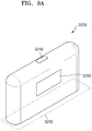
- FIGS. 9A and 9B are diagrams showing various views of an example of a cradle.
- FIG. 9A is a diagram showing an example of the cradle 3200 viewed in a first direction.
- the inner space 3230 into which the holder 3100 may be inserted may be formed on one side of the cradle 3200.
- the holder 3100 may be inserted and fixed in the cradle 3200 even when the cradle 3200 does not include a separate fixing unit like a lid.
- the cradle 3200 may also include a button 240 for a user to control the cradle 3200 and a display 250 for outputting an image.
- FIG. 9B is a diagram showing an example of the cradle 3200 viewed in a second direction.
- the cradle 3200 may include a terminal 3260 to be coupled with the inserted holder 3100.
- the battery 3110 of the holder 3100 may be charged by power supplied by the battery 3210 of the cradle 3200 as the terminal 3260 is coupled with the terminal 3170 of the holder 3100.
- the holder 3100 may be operated by power supplied from the battery 3210 of the cradle 3200 through the terminal 3170 and the terminal 3260.
- transmission/reception of signals may be performed between the holder 3100 and the cradle 3200 through the terminal 3170 and the terminal 3260.
- the terminal 3260 may include four micro pins, but the present disclosure is not limited thereto.
- the holder 3100 may be inserted into the inner space 3230 of the cradle 3200, as described above with reference to FIGS. 6 to 9B .
- the holder 3100 may be completely inserted into the cradle 3200 or may be tilted while the holder 3100 is inserted into the cradle 3200.
- examples in which the holder 3100 is inserted into the cradle 3200 will be described with reference to FIGS. 10 to 12B .
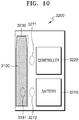
- FIG. 10 is a diagram showing an example in which a holder is inserted into a cradle.
- the cradle 3200 may not include another component (e.g., a lid) for not exposing the holder 3100 to the outside.
- the cradle 3200 may include at least one attaching member 3271 and/or 3272 to strengthen the coupling with the holder 3100. Also, at least one attaching member 3181 may be included in the holder 3100 as well. Here, attaching members 3181, 3271, and 3272 may be magnets, but are not limited thereto. Although FIG. 5 shows that the holder 3100 includes one attaching member 181 and the cradle 3200 includes two attaching members 3271 and 3272 for convenience of explanation, the number of the attaching members 3181, 3271, and 3272 is not limited thereto.
- the holder 3100 may include the attaching member 181 at a first position and the cradle 3200 may include the attaching members 3271 and 3272 at a second position and a third position, respectively.
- the first position and the third position may be facing each other when the holder 3100 is inserted into the cradle 3200.
- the holder 3100 and the cradle 3200 may be attached to each other more strongly when the holder 3100 is inserted into one side surface of the cradle 3200.
- the holder 3100 and the cradle 3200 may be attached to each other more strongly. Therefore, even when there is no separate component (e.g., a lid) in the cradle 3200, the inserted holder 3100 may not be easily separated from the cradle 3200.
- the controller 3220 may charge the battery 3110 of the holder 3100 by using power of the battery 3210.
- FIG. 11 is a diagram showing an example in which a holder is tilted while being inserted into a cradle.
- the holder 3100 is tilted inside the cradle 3200.
- the term 'tilting' indicates that the holder 3100 is inclined at a certain angle while the holder 3100 is inserted into the cradle 3200.
- a user when the holder 3100 is completely inserted into the cradle 3200, a user may not smoke. In other words, once the holder 3100 is completely inserted into the cradle 3200, a cigarette may not be inserted into the holder 3100. Therefore, when the holder 3100 is completely inserted into the cradle 3200, a user may not smoke.
- the holder 3100 when the holder 3100 is tilted, the terminal end 3141 of the holder 3100 is exposed to the outside. Therefore, the user may insert a cigarette into the terminal end 3141 and inhale (smoke) generated aerosol.
- a sufficient tilting angle ⁇ may be secured to prevent a cigarette from being bent or damaged when the cigarette is inserted into the terminal end 3141 of the holder 3100.
- the holder 3100 may be tilted at a minimum angle at which an entire cigarette insertion hole included in the terminal end 3141 is exposed to the outside or an angle greater than the minimum angle.
- the range of the tilting angle ⁇ may be from 0° to 180° and may preferably be from 5° to 90°.
- the range of the tilting angle ⁇ may be from 5° to 20°, from 5° to 30°, from 5° to 40°, from 5° to 50°, or from 5° to 60°. Even more preferably, the tilting angle ⁇ may be 10°.
- the terminal 3170 of the holder 3100 and the terminal 3260 of the cradle 3200 are still coupled with each other. Therefore, the heater 3130 of the holder 3100 may be heated by power supplied by the battery 3210 of the cradle 3200. Therefore, the holder 3100 may generate aerosol by using the battery 3210 of the cradle 3200 even when the remaining power of the battery 3110 of the holder 3100 is low or the battery 3110 of the holder 3100 is completely discharged.
- FIG. 11 shows an example in which the holder 3100 includes one attaching member 3182 and the cradle 3200 includes two attaching members 3273 and 3274.
- the respective positions of the attaching members 3182, 3273, and 3274 are as described above with reference to FIG. 10 .
- the attaching members 3182, 3273, and 3274 are magnets
- the magnetic strength of the attaching member 3274 may be greater than the magnetic strength of the attaching member 3273. Therefore, the holder 3100 may not be completely separated from the cradle 3200 due to the attaching member 182 and the attaching member 274 even when the holder 3100 is tilted.
- the controller 3220 may heat the heater 3130 of the holder 3100 or charge the battery 3110, by using power of the battery 3210.
- FIGS. 12A to 12B are diagrams showing examples in which a holder is inserted into a cradle
- FIG. 12A shows an example in which the holder 3100 is completely inserted into the cradle 3200.
- the cradle 3200 may be fabricated to provide the sufficient inner space 3230 of the cradle 3200 to minimize the contact of a user with the holder 3100 when the holder 3100 is completely inserted into the cradle 3200.
- the controller 3220 supplies power of the battery 3210 to the holder 3100, such that the battery 3110 of the holder 3100 is charged.
- FIG. 12B shows an example in which the holder 3100 is tilted while being inserted into the cradle 3200.
- the controller 3220 supplies power of the battery 3210 to the holder 3100, such that the battery 3110 of the holder 3100 is charged or the heater 3130 of the holder 3100 is heated.
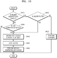
- FIG. 13 is a flowchart for describing an example in which a holder and a cradle operates.
- a method for generating aerosol shown in FIG. 13 includes operations that are performed in a time-series manner by the holder 3100 or the cradle 3200 shown in FIGS. 6 or 8 . Therefore, it will be understood that the descriptions given above with respect to the holder 3100 and the cradle 3200 shown in FIGS. 6 or 8 also apply to the method of FIG. 13 , even when the descriptions are omitted below.
- the holder 3100 determines whether it is inserted in the cradle 3200.
- the controller 3120 may determine whether the holder 3100 is inserted into the cradle 3200 based on whether the terminals 3170 and 3260 of the holder 3100 and the cradle 3200 are connected to each other and/or whether the attaching members 3181, 3271, and 3272 are operating.
- the method proceeds to operation 3820.
- the holder 3100 is separated from the cradle 3200, the method proceeds to operation 3830.
- the cradle 3200 determines whether the holder 3100 is tilted. For example, the controller 3220 may determine whether the holder 3100 is inserted into the cradle 3200 based on whether the terminals 3170 and 3260 of the holder 3100 and the cradle 3200 are connected to each other and/or whether attaching members 3182, 3273, and 3274 are operating.
- the controller 3120 of the holder 3100 may determine whether the holder 3100 is tilted.
- the method proceeds to operation 3840.
- the holder 3100 is not tilted (i.e., the holder 3100 is completely inserted into the cradle 3200)
- the method proceeds to operation 3870.
- the holder 3100 determines whether conditions of using the holder 3100 are satisfied. For example, the controller 3120 may determine whether the conditions for using the holder 3100 are satisfied by checking whether the remaining power of the battery 3110 and whether other components of the holder 3100 may be normally operated.
- the holder 3100 informs a user that the holder 3100 is ready to be used.
- the controller 3120 may output an image indicating that the holder 3100 is ready to be used, on the display of the holder 3100, or may control the motor of the holder 3100 to generate a vibration signal.
- the heater 3130 is heated.
- the heater 3130 may be heated by power of the battery 3110 of the holder 3100.
- the heater 3130 may be heated by power of the battery 3210 of the cradle 3200.
- the controller 3120 of the holder 3100 or the controller 3220 of the cradle 3200 may check the temperature of the heater 3130 in real time and control an amount of power supplied to the heater 3130 and a time for supplying the power to the heater 3130.
- the controller 3120 or 3220 may check the temperature of the heater 3130 in real time through a temperature sensor included in the holder 3100 or an electrically conductive track of the heater 3130.
- the holder 3100 performs an aerosol generation mechanism.
- the controller 3120, 3220 may check the temperature of the heater 3130, which changes as a user performs puffs, and adjust an amount of power supplied to the heater 3130 or stop supplying power to the heater 3130. Also, the controller 3120 or 3220 may count the number of puffs of the user and output information indicating that the holder 3100 needs to be cleaned when the number of puffs reaches a certain number of times (e.g., 1500 times).
- the cradle 3200 performs charging of the holder 3100.
- the controller 3220 may charge the holder 3100 by supplying power of the battery 3210 of the cradle 3200 to the battery 3110 of the holder 3100.
- the controller 3120 or 3220 may stop the operation of the holder 3100 according to the number of puffs of the user or the operation time of the holder 3100.
- the controller 3120 or 3220 stops the operation of the holder 3100 will be described with reference to FIG. 14 .
- FIG. 14 is a flowchart for describing an example in which a holder operates.
- a method for generating aerosols shown in FIG. 14 includes operations that are performed in a time-series manner by the holder 3100 and the cradle 3200 shown in FIGS. 6 or 8 . Therefore, it will be understood that the descriptions given above with respect to the holder 3100 and the cradle 3200 shown in FIGS. 6 or 8 also apply to the method of FIG. 14 , even when the descriptions are omitted below.
- the controller 3120 or 3220 determines whether a user puffed. For example, the controller 3120 or 3220 may determine, through the puff detecting sensor included in the holder 3100, whether the user puffed. Alternatively, the controller 3120 or 3220 may determine whether the user puffed, by using the resistance change of the electrically conductive track included in the heater 3130.
- the electrically conductive track includes an electrically conductive track for generating heat and/or an electrically conductive track for sensing temperature. Alternatively, the controller 3120 or 3220 may determine whether the user puffed, by using both the resistance change of the electrically conductive track included in the heater 3130 and the puff detecting sensor.
- aerosol is generated according to the puff of the user.
- the controller 3120 or 3220 may adjust power supplied to the heater 3130 according to the puff of the user the temperature of the heater 3130, as described above with reference to FIG. 13 . Also, the controller 3120 or 3220 counts the number of puffs of the user.
- the controller 3120 or 3220 determines whether the number of puffs of the user equal to or greater than a puff limit number. For example, assuming that the puff limit number is set to 14, the controller 3120 or 3220 determines whether the number of counted puffs is 14 or more. However, the puff limit number is not limited to 14. For example, the puff limit number may be set to an appropriate number of times selected in the range of 10 to 16.
- the controller 3120 or 3220 may output a warning signal through a display or a vibration motor.
- the method proceeds to operation 3950.
- the method proceeds to operation 3940.
- the controller 3120 or 3220 determines whether the operation time of the holder 3100 is equal to or greater than an operation limit time.
- the operation time of the holder 3100 refers to accumulated time from a time point at which the holder 3100 started its operation to a current time point. For example, assuming that the operation limit time is set to 10 minutes, the controller 3120 or 4220 determines whether the holder 3100 is operating for 10 minutes or longer.
- the controller 3120 or 3220 may output a warning signal through a display or a vibration motor.
- the method proceeds to operation 3950.
- the operation time of the holder 3100 is less than the operation limit time, the method proceeds to operation 3920.
- the controller 3120 or 3220 forcibly terminates the operation of the holder 3100.
- the controller 3120 or 3220 terminates the aerosol generation mechanism of the holder 3100.
- the controller 3120 or 3220 may forcibly terminate the operation of the holder 3100 by interrupting the power supplied to the heater 3130.
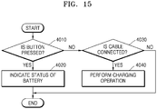
- FIG. 15 is a flowchart for illustrating operations of a cradle, according to an exemplary embodiment.
- the flowchart shown in FIG. 15 includes operations that are performed in a time-series manner by the cradle 3200 shown in FIG. 8 . Therefore, it will be understood that the descriptions given above with respect to the cradle 3200 shown in FIG. 8 also apply to the method of FIG. 15 , even when the descriptions are omitted below.
- the operation of the cradle 3200 to be described below may be performed regardless of whether the holder 3100 is inserted into the cradle 3200.
- the controller 3220 of the cradle 3200 determines whether the button 3240 is pressed. When the button 3240 is pressed, the method proceeds to operation 4020. When the button 3240 is not pressed, the method proceeds to operation 4030.
- the cradle 3200 indicates the status of the battery 3210.
- the controller 3220 may output information regarding the current state of the battery 3210 (e.g., remaining power, etc.) on the display 3250.
- the controller 3220 of the cradle 3200 determines whether a cable is connected to the cradle 3200. For example, the controller 3220 determines whether a cable is connected to an interface (e.g., a USB port, etc.) included in the cradle 3200. When a cable is connected to the cradle 3200, the method proceeds to operation 4040. Otherwise, the procedure is terminated.
- an interface e.g., a USB port, etc.
- the cradle 3200 performs a charging operation.
- the cradle 3200 charges the battery 3210 by using power supplied through a connected cable.
- a cigarette may be inserted into the holder 3100.
- the cigarette includes an aerosol generating material and aerosol is generated by the heated heater 3130.
- FIG. 16 is a diagram showing an example in which a cigarette is inserted into a holder.
- the cigarette 3300 may be inserted into the holder 3100 through the terminal end 3141 of the casing 3140.
- the heater 3130 is located inside the cigarette 3300. Therefore, the heated heater 3130 heats the aerosol generating material of the cigarette 3300, thereby generating aerosol.
- the cigarette 3300 may be similar to a typical combustive cigarette.
- the cigarette 3300 may include a first portion 3310 containing an aerosol generating material and a second portion 3320 including a filter and the like.
- the cigarette 3300 according to an exemplary embodiment may also include an aerosol generating material in the second portion 3320.
- an aerosol generating material in the form of granules or capsules may be inserted into the second portion 3320.
- the entire first portion 3310 may be inserted into the holder 3100 and the second portion 3320 may be exposed to the outside. In another example, only a portion of the first portion 3310 may be inserted into the holder 3100. In another example, the entire first portion 3310 and a portion the second portion 3320 may be inserted into the holder 3100.
- a user may inhale the aerosol while holding the second portion 3320 by mouth.
- the aerosol is generated as the outside air passes through the first portion 3310, and the generated aerosol passes through the second portion and is delivered to a user's mouth.
- the outside air 5120 may be introduced through at least one air passage formed in the holder 3100.
- opening and closing of the air passage formed in the holder 3100 and/or the size of the air passage may be adjusted by a user. Accordingly, an amount of smoke and a smoking impression may be adjusted by the user.
- the outside air 5110 may be introduced through at least one hole formed in the surface of the cigarette 3300.
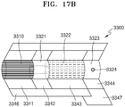
- FIGS. 17A and 17B are block diagrams showing examples of a cigarette.
- the cigarette 3300 includes a tobacco rod 3310, a first filter segment 3321, a cooling structure 3322, and a second filter segment 3323.
- the first portion 3310 described above with reference to FIG. 16 includes the tobacco rod 3310
- the second portion 3320 includes the first filter segment 3321, the cooling structure 3322, and the second filter segment 3323.
- the cigarette 3300 may be packaged by a total of five wrappers 3341, 3342, 3343, 3344, and 3345. Meanwhile, referring to FIG. 17B , the cigarette 3300 may be packaged by a total of six wrappers 3341, 3342, 3343, 3344, 3346 and 3347.
- the tobacco rod 3310 is packed by a first wrapper 3341, and the first filter segment 3321 is packaged by a second wrapper 3342.
- the cooling structure 3322 is packed by a third wrapper 3343, and the second filter segment 3323 is packed by a fourth wrapper 3344.
- a fifth wrapper 3345 of FIG. 17A may be wrapped around the first wrapper 3341, the second wrapper 3342, the third wrapper 3343, and the fourth wrapper 3344. In other words, the entire cigarette 3300 may be double-packaged by the fifth wrapper 3345.
- a sixth wrapper 3346 of FIG. 17B may be wrapped around the first wrapper 3341, the second wrapper 3342, and the third wrapper 3343.
- the tobacco rod 3310, the first filter segment 3321, and the cooling structure 3322 of the cigarette 3300 may be double-packaged by the sixth wrapper 3346.
- a seventh wrapper 3347 of FIG. 17B may be wrapped around at least a portion of the third wrapper 3343 and the fourth wrapper 3344. In other words, at least a portion of the cooling structure 3322 and the second filter segment 3323 of the cigarette 3300 may be re-packaged by the seventh wrapper 3347.
- the first wrapper 3341 and the second wrapper 3342 may be fabricated using a general filter wrapping paper.
- the first wrapper 3341 and the second wrapper 3342 may include a porous wrapping paper or a non-porous wrapping paper.
- the first wrapper 3341 and the second wrapper 3342 may be made of an oil-resistant paper sheet and an aluminum laminate packaging material.
- the third wrapper 3343 may be made of a hard wrapping paper.
- the basis weight of the third wrapper 3343 may be, but is not limited to, 90 g/m 2 .
- the fourth wrapper 3344 may be made of an oil-resistant hard wrapping paper.
- the basis weight of the fourth wrapper 3344 may be 92 g/m 2 and the thickness thereof may be 125 ⁇ m, but the present disclosure is not limited thereto.
- the fifth wrapper 3345, the sixth wrapper 3346, and the seventh wrapper 3347 may be made of a sterilized paper (MFW).
- MFW refers to a paper specially manufactured to have the tensile strength, the water resistance, the smoothness, and the like that are improved compared to those of ordinary paper.
- the basis weight of the fifth wrapper 3345, the sixth wrapper 3346, and the seventh wrapper 3347 may be 60 g/m 2 and the thickness thereof may be 67 m, but the present disclosure is not limited thereto.
- the tensile strengths of the fifth wrapper 3345, the sixth wrapper 3346, and the seventh wrapper 3347 may be within the range of 8 kgf/15 mm to 11 kgf/15 mm for dry type and may be 1.0 kgf/15 mm for wet type, but the present disclosure is not limited thereto.
- a predetermined material may be included in the fifth wrapper 3345, the sixth wrapper 3346, and the seventh wrapper 3347.
- an example of the predetermined material may be, but is not limited to, silicon.
- silicon exhibits characteristics like heat resistance with little change due to the temperature, oxidation resistance, resistances to various chemicals, water repellency, electrical insulation, etc.
- any material other than silicon may be applied to (or coated on) the fifth wrapper 3345, the sixth wrapper 3346, and the seventh wrapper 3347 without limitation as long as the material exhibits the above-mentioned characteristics.
- the fifth wrapper 3345, the sixth wrapper 3346, and the seventh wrapper 3347 may prevent the cigarette 3300 from being burned.
- the tobacco rod 3310 is heated by the heater 3130, there is a possibility that the cigarette 3300 is burned.
- the temperature is raised to a temperature above the ignition point of any one of materials included in the tobacco rod 3310, the cigarette 3300 may be burned.
- the fifth wrapper 3345, the sixth wrapper 3346, and the seventh wrapper 3347 include a non-combustible material, the burning of the cigarette 3300 may be prevented.
- the fifth wrapper 3345, the sixth wrapper 3346, and the seventh wrapper 3347 may prevent the holder 3100 from being contaminated by substances formed by the cigarette 3300.
- liquid substances may be formed in the cigarette 3300.
- liquid materials e.g., moisture, etc.
- the fifth wrapper 3345, the sixth wrapper 3346, and the seventh wrapper 3347 wrap the tobacco rod 3310 and/or the first filter segment 3321, the liquid materials formed in the cigarette 3300 may be prevented from being leaked out of the cigarette 3300. Accordingly, the casing 3140 of the holder 3100 and the like may be prevented from being contaminated by the liquid materials formed by the cigarette 3300.
- the diameter of the cigarette 3300 may be within the range of 5 mm to 9 mm, and the length thereof may be about 48 mm. However, the present disclosure is not limited thereto. Preferably, the diameter of the cigarette 3300 may be 7.2 mm, but is not limited thereto. In addition, the length of the tobacco rod 3310 may be about 12 mm, the length of the first filter segment 3321 may be about 10 mm, the length of the cooling structure 3322 may be about 14 mm, and the length of the second filter segment 3323 may be about 12 mm, but the present disclosure is not limited thereto.
- the structures of the cigarette 3300 shown in FIGS. 17A and 17B are merely examples, and some of the components may be omitted.
- the cigarette 3300 may not include one or more of the first filter segment 3321, the cooling structure 3322, and the second filter segment 3323.
- the tobacco rod 3310 includes an aerosol generating material.
- the aerosol generating material may include at least one of glycerin, propylene glycol, ethylene glycol, dipropylene glycol, diethylene glycol, triethylene glycol, tetraethylene glycol, and oleyl alcohol.
- the tobacco rod 3310 may include other additive materials like a flavoring agent, a wetting agent, and/or an organic acid.
- the flavoring agent may include licorice, sucrose, fructose syrup, isosweet, cocoa, lavender, cinnamon, cardamom, celery, fenugreek, cascara, sandalwood, bergamot, geranium, honey essence, rose oil, vanilla, lemon oil, orange oil, mint oil, cinnamon, keragene, cognac, jasmine, chamomile, menthol, cinnamon, ylang ylang, salvia, spearmint, ginger, coriander, coffee, etc.
- the wetting agent may include glycerin or propylene glycol.
- the tobacco rod 3310 may be filled with cut tobacco leaves.
- cut tobacco leaves may be formed by fine-cutting a tobacco sheet.
- the tobacco rod 3310 may be filled with a plurality of cigarette strands formed by fine-cutting a tobacco sheet.
- the tobacco rod 3310 may be formed by combining a plurality of tobacco strands in the same direction (parallel to one another) or randomly.
- the tobacco rod 3310 may be formed by combining a plurality of tobacco strands, and a plurality of vertical channels through which the heater 3130 may be inserted or aerosol may pass may be formed. At this time, depending on the sizes and arrangements of the tobacco strands, the vertical channels may be uniform or non-uniform.
- tobacco strands may be formed through the following operations.
- a raw tobacco material is pulverized to form a slurry in which an aerosol generating material (e.g., glycerin, propylene glycol, etc.), a flavoring liquid, a binder (e.g., guar gum, xanthan gum, carboxymethyl cellulose (CMC), etc.), and water are mixed, and then a sheet is formed by using the slurry.
- an aerosol generating material e.g., glycerin, propylene glycol, etc.
- a binder e.g., guar gum, xanthan gum, carboxymethyl cellulose (CMC), etc.
- water e.g., guar gum, xanthan gum, carboxymethyl cellulose (CMC), etc.
- a sheet is formed by using the slurry.
- natural pulp or cellulose may be added to modify the physical properties of tobacco strands, and one or more binders may
- the raw tobacco material may be tobacco leaf fragments, tobacco stems, and/or fine tobacco powders formed during treatment of tobacco.
- the tobacco sheet may also include other additives like wood cellulose fibers.
- the slurry may contain 5% to 40% aerosol generating material, and 2% to 35% aerosol generating material may remain in completed tobacco strands. Preferably, 10% to 25% of the aerosol generating material may remain in the completed tobacco strands.
- a flavoring liquid like a menthol or a moisturizer may be spray-added to the center of the tobacco rod 3310.
- the tobacco strands may be fabricated to have cuboidal shapes having horizontal lengths from 0.5 mm to 2 mm, vertical lengths from 5 mm to 50 mm, and thicknesses (heights) from 0.1 mm to 0.3 mm, but the present disclosure is not limited thereto.
- the tobacco strands may be fabricated to have a cuboidal shape having the horizontal length of 0.9 mm, the vertical length of 20 mm, and the thickness (height) of 0.2 mm.
- one tobacco strand may be fabricated to have a basis weight from 100 g/m 2 to 250 g/m 2 , but the present disclosure is not limited thereto.
- one tobacco strand may be fabricated to have a basis weight of 180 g/m 2 .
- the tobacco rod 3310 filled with tobacco strands may generate a greater amount of aerosol.
- tobacco strands ensure a wider surface area. A wider surface area indicates that an aerosol generating material has a greater chance of contacting the outside air. Therefore, when the tobacco rod 3310 is filled with tobacco strands, more aerosol may be generated when compared with the tobacco rod 3310 filled with a tobacco sheet.
- the tobacco rod 3310 filled with tobacco strands may be separated more easily than the tobacco rod 3310 filled with a tobacco sheet.
- the tobacco rod 3310 may be more easily separated from the holder 3100 than the tobacco sheet 310 filled with a tobacco sheet.
- the first filter segment 3321 may be a cellulose acetate filter.
- the first filter segment 3321 may have a tubular structure including a hollow therein.
- the length of the first filter segment 3321 may be any suitable length within the range of 4 mm to 30 mm, but is not limited thereto.
- the length of the first filter segment 3321 may be 10 mm, but is not limited thereto.
- the diameter of the hollow included in the first filter segment 3321 may be any suitable diameter within the range of 3 mm to 4.5 mm, but is not limited thereto.
- the hardness of the first filter segment 3321 may be adjusted by adjusting the content of a plasticizer during fabrication of the first filter segment 3321.
- the first filter segment 3321 may be wrapped by a wrapper. Therefore, the first filter segment 3321 may be easily combined with other components (e.g., other filter segments).
- the first filter segment 3321 may be fabricated by inserting structures of the same type or different types like films or tubes thereinto (e.g., into the hollow).
- the first filter segment 3321 may be fabricated using cellulose acetate. Therefore, the inner material of the tobacco rod 3310 may be prevented from being pushed back when the heater 3130 is inserted, and the effect of cooling an aerosol may occur.
- the cooling structure 3322 cools aerosol generated as the heater 3130 heats the tobacco rod 3310. Therefore, a user may inhale aerosol cooled to a suitable temperature.
- the length or the diameter of the cooling structure 3322 may vary depending on the shape of the cigarette 3300.
- the length of the cooling structure 3322 may be suitably selected within the range of 7 mm to 20 mm.
- the length of the cooling structure 3322 may be about 14 mm, but is not limited thereto
- the cooling structure 3322 may be made of pure polylactic acid or may be made of a combination of other degradable polymers and polylactic acid.
- the cooling structure 3322 may be manufactured by an extrusion method or a weaving method of fibers.
- the cooling structure 3322 can be manufactured in various forms to increase the surface area (i.e., surface area in contact with the aerosol) per unit area.
- the cooling structure 3322 can be made by weaving fibers made of polylactic acid.
- a fragrance liquid may be applied to the fibers made of polylactic acid.
- the cooling structure 3322 may be manufactured by using fibers applied to the fragrance liquid and fibers made of polylactic acid.
- the polylactic acid fibers may be dyed in a predetermined color, and a cooling structure 3322 may be manufactured using the dyed fibers.
- cooling structure 3322 are described below with reference to FIGS. 18A to 18F .
- the second filter segment 3323 may also be a cellulose acetate filter.
- the second filter segment 3323 may be fabricated as a recess filter, but is not limited thereto.
- the length of the second filter segment 3323 may be appropriately selected within the range of 4 mm to 20 mm.
- the length of the second filter segment 3323 may be about 12 mm, but is not limited thereto.
- the second filter segment 3323 may be fabricated to generate a flavor by spraying a flavoring liquid to the second filter segment 3323 during fabrication of the second filter segment 3323.
- separate fibers coated with a flavoring liquid may be inserted into the second filter segment 3323. Aerosol formed in the tobacco rod 3310 is cooled as it passes through the cooling structure 3322, and the cooled aerosol is delivered to a user through the second filter segment 3323. Therefore, when a flavoring material is added to the second filter segment 3323, the effect of enhancing the persistence of a flavor delivered to the user may occur.
- the second filter segment 3323 may include at least one capsule 3324.
- the capsule 3324 may have a structure in which a content liquid containing a flavoring material is wrapped with a film.
- the capsule 3324 may have a spherical or cylindrical shape.
- the film of the capsule 3324 may be fabricated by using a material including agar, pectin, sodium alginate, carrageenan, gelatin, or a gum like guar gum.
- a gelling agent may be further used as a material for forming the film of the capsule 3324.
- a calcium chloride group may be used.
- a plasticizer may be further used as a material for forming the film of the capsule 3324.
- glycerin and/or sorbitol may be used.
- a coloring agent may be further used as a material for forming the film of the capsule 3324.
- menthol for example, menthol, plant essential oil, and the like may be used.
- a solvent of the flavoring material included in the content liquid for example, a medium chain fatty acid triglyceride (MCT) may be used.
- the content liquid may include other additives like a figment, an emulsifying agent, a thickening agent, etc.
- FIGS. 18A to 18F are diagrams for describing an example of a cooling structure of a cigarette.
- the cooling structure shown in FIGS. 18A to 18F can be manufactured using fibers produced from pure polylactic acid (PLA).
- PLA polylactic acid
- the film (sheet) when the film (sheet) is filled to produce a cooling structure for the film (sheet), the film (sheet) may be broken by an external impact. In this case, the cooling effect of the cooling structure is reduced.
- cooling structure when manufacturing a cooling structure by extrusion molding or the like, as the process of cutting the structure is added, the efficiency of the process is lowered. There is also a limitation in manufacturing the cooling structure in various shapes.
- the risk that the cooling structure is deformed or damaged by external impacts can be lowered.
- the manner of combining the fibers it is possible to produce a cooling structure having a variety of shapes.
- the cooling structure with the fibers, the surface area in contact with the aerosol is increased.
- the cooling effect of the cooling structure can be further improved.
- the cooling structure 6310 may be manufactured in a cylindrical shape, and at least one air passage 6311 may be formed in a cross section of the cooling structure 6310.
- the cooling structure 6320 may be manufactured as a structure in which a plurality of fibers are entangled with each other.
- the aerosol may flow between the fibers, and vortex may be formed according to the shape of the cooling structure 6320.
- the vortex formed widens the area that aerosol contacts in the cooling structure 6320 and increases the time the aerosol stays in the cooling structure 6320.
- the heated aerosol can be cooled effectively.
- the cooling structure 6330 may be manufactured in the form of a plurality of bundles 6321.
- the cooling structure 6340 may be filled with granules made of polylactic acid, vinegar or charcoal, respectively.
- Granules may also be prepared from a mixture of polylactic acid, vinegar and charcoal.
- the granules may further include elements capable of increasing the cooling effect of the aerosol in addition to polylactic acid, vinegar and/or charcoal.
- the cooling structure 6350 may include a first cross-section 6351 and a second cross-section 6352.
- the first cross section 6351 borders the first filter segment 3321 and may include a void into which the aerosol flows.
- the second cross section 6352 borders the second filter segment 3323 and may include a void through which the aerosol may be released.
- the first cross-section 6351 and the second cross-section 6352 may include a single void having the same diameter, but the diameter and number of the voids included in the first cross-section 6351 and the second cross-section 6352 Is not limited thereto.
- the cooling structure 6350 may include a third cross section 6353 including a plurality of voids between the first cross section 6351 and the second cross section 6352.
- the diameters of the plurality of voids included in the third cross section 6535 may be smaller than the diameters of the voids included in the first cross section 6351 and the second cross section 6352.
- the number of voids included in the third cross section 6353 may be greater than the number of voids included in the first cross section 6351 and the second cross section 6352.
- the cooling structure 6360 may include a first cross section 6361 bordering the first filter segment 3321 and a second cross section 6362 bordering the second filter segment 3323.
- cooling structure 6360 may include one or more tubular elements 6363.
- the tubular element 6363 can penetrate the first cross section 6361 and the second cross section 6362.
- the tubular element 6363 may be packaged in a microporous package and filled with a filler (e.g., the granules described above with reference to FIG. 18D ) that may increase the cooling effect of the aerosol.
- the holder can generate aerosol by heating the cigarette. It is also possible to produce aerosol either independently from the holder or while the holder inserted into the cradle and tilted. In particular, when the holder is tilted, the heater may be heated by the power of the battery of the cradle.
- the above-described method can be written as a program that can be executed in a computer, it can be implemented in a general-purpose digital computer to operate the program using a computer-readable recording medium.
- the structure of the data used in the above-described method can be recorded on the computer-readable recording medium through various means.
- the computer-readable recording medium may include a storage medium such as a magnetic storage medium (e.g., ROM, RAM, USB, floppy disk, hard disk, etc.), an optical reading medium (e.g., CD-ROM, DVD, etc.).
Landscapes
- Engineering & Computer Science (AREA)
- Health & Medical Sciences (AREA)
- Human Computer Interaction (AREA)
- Computer Networks & Wireless Communication (AREA)
- Biomedical Technology (AREA)
- Heart & Thoracic Surgery (AREA)
- Chemical Kinetics & Catalysis (AREA)
- Bioinformatics & Cheminformatics (AREA)
- Pulmonology (AREA)
- Anesthesiology (AREA)
- Chemical & Material Sciences (AREA)
- General Chemical & Material Sciences (AREA)
- Hematology (AREA)
- Life Sciences & Earth Sciences (AREA)
- Animal Behavior & Ethology (AREA)
- General Health & Medical Sciences (AREA)
- Public Health (AREA)
- Veterinary Medicine (AREA)
- Secondary Cells (AREA)
- Fuel Cell (AREA)
Applications Claiming Priority (3)
| Application Number | Priority Date | Filing Date | Title |
|---|---|---|---|
| KR1020170100888 | 2017-08-09 | ||
| KR1020180018693A KR102138872B1 (ko) | 2017-04-11 | 2018-02-14 | 에어로졸 생성 장치 및 에어로졸 생성 장치 제어 방법 |
| PCT/KR2018/009100 WO2019031877A2 (fr) | 2017-08-09 | 2018-08-09 | Dispositif de génération d'aérosol et procédé de régulation pour dispositif de génération d'aérosol |
Publications (2)
| Publication Number | Publication Date |
|---|---|
| EP3666095A2 true EP3666095A2 (fr) | 2020-06-17 |
| EP3666095A4 EP3666095A4 (fr) | 2021-11-24 |
Family
ID=88558914
Family Applications (1)
| Application Number | Title | Priority Date | Filing Date |
|---|---|---|---|
| EP18844735.3A Pending EP3666095A4 (fr) | 2017-08-09 | 2018-08-09 | Dispositif de génération d'aérosol et procédé de régulation pour dispositif de génération d'aérosol |
Country Status (5)
| Country | Link |
|---|---|
| US (1) | US11641879B2 (fr) |
| EP (1) | EP3666095A4 (fr) |
| JP (1) | JP6930690B2 (fr) |
| CN (2) | CN116172276A (fr) |
| WO (1) | WO2019031877A2 (fr) |
Cited By (5)
| Publication number | Priority date | Publication date | Assignee | Title |
|---|---|---|---|---|
| EP3817603B1 (fr) | 2019-04-30 | 2022-10-12 | KT&G Corporation | Dispositif de production d'aérosol et son procédé de fonctionnement |
| EP4093220A4 (fr) * | 2020-09-11 | 2023-09-13 | KT&G Corporation | Système en boîtier et appareil de génération d'aérosol le comprenant |
| WO2024064670A1 (fr) * | 2022-09-19 | 2024-03-28 | Altria Client Services Llc | Système de commande de puissance |
| US12520880B2 (en) | 2021-01-18 | 2026-01-13 | Altria Client Services Llc | Heat-not-burn (HNB) aerosol-generating devices including energy based heater control, and methods of controlling a heater |
| US12550942B2 (en) | 2022-09-19 | 2026-02-17 | Altria Client Services Llc | Session control system |
Families Citing this family (25)
| Publication number | Priority date | Publication date | Assignee | Title |
|---|---|---|---|---|
| US10517326B2 (en) * | 2017-01-27 | 2019-12-31 | Rai Strategic Holdings, Inc. | Secondary battery for an aerosol delivery device |
| GB201903245D0 (en) | 2019-03-11 | 2019-04-24 | Nicoventures Trading Ltd | Aerosol provision device |
| GB201903248D0 (en) | 2019-03-11 | 2019-04-24 | Nicoventures Trading Ltd | Aerosol provision device |
| JP6678936B1 (ja) | 2019-05-31 | 2020-04-15 | 日本たばこ産業株式会社 | エアロゾル吸引器用の制御装置及びエアロゾル吸引器 |
| JP6625258B1 (ja) * | 2019-05-31 | 2019-12-25 | 日本たばこ産業株式会社 | エアロゾル吸引器、エアロゾル吸引器用の制御装置、エアロゾル吸引器の制御方法及びプログラム |
| EP3979847B1 (fr) * | 2019-06-10 | 2024-02-28 | Philip Morris Products S.A. | Emballage stable pour article de génération d'aérosol |
| CN116075243A (zh) * | 2020-06-10 | 2023-05-05 | 电子烟研究所公司 | 气溶胶供应设备 |
| KR102581003B1 (ko) * | 2020-06-15 | 2023-09-21 | 주식회사 케이티앤지 | 무화량이 향상된 에어로졸 발생 물품 |
| WO2021260089A1 (fr) * | 2020-06-24 | 2021-12-30 | Philip Morris Products S.A. | Dispositif de génération d'aérosol et système comprenant un module de communication dynamique en champ proche |
| CN111869930A (zh) * | 2020-06-30 | 2020-11-03 | 上海烟草集团有限责任公司 | 一种供电装置及气雾产生装置 |
| KR102538129B1 (ko) * | 2020-07-03 | 2023-05-30 | 주식회사 케이티앤지 | 히터 조립체, 및 에어로졸 생성 시스템 |
| US12127597B2 (en) * | 2020-09-07 | 2024-10-29 | Kt&G Corporation | Induction heating type aerosol generating device capable of changing an operation mode of a power converter |
| JP6890203B1 (ja) | 2020-09-30 | 2021-06-18 | 日本たばこ産業株式会社 | エアロゾル生成装置の電源ユニット |
| KR102525015B1 (ko) | 2020-11-11 | 2023-04-24 | 주식회사 케이티앤지 | 보호회로 모듈 및 이를 포함하는 에어로졸 생성장치 |
| EP4212038A4 (fr) * | 2020-12-15 | 2024-07-24 | Japan Tobacco Inc. | Dispositif d?inhalation, procédé de commande et programme |
| US11789476B2 (en) * | 2021-01-18 | 2023-10-17 | Altria Client Services Llc | Heat-not-burn (HNB) aerosol-generating devices including intra-draw heater control, and methods of controlling a heater |
| EP4087423A4 (fr) * | 2021-03-25 | 2023-07-12 | KT&G Corporation | Appareil de génération d'aérosol et son procédé de fonctionnement |
| KR102697383B1 (ko) * | 2021-09-02 | 2024-08-22 | 주식회사 케이티앤지 | 히터에 대한 전력 공급을 제어하는 에어로졸 생성 장치 및 그의 동작 방법 |
| EP4418936A4 (fr) * | 2021-10-19 | 2025-08-20 | Kt & G Corp | Dispositif de génération d?aérosol et son procédé de fonctionnement |
| KR102759644B1 (ko) * | 2021-11-19 | 2025-02-04 | 주식회사 케이티앤지 | 가향 시트를 포함하는 지관 및 이를 포함하는 흡연 물품 |
| GB202205932D0 (en) * | 2022-04-22 | 2022-06-08 | Nicoventures Trading Ltd | Aerosol provision device or vapour provision |
| US20250288019A1 (en) * | 2022-05-09 | 2025-09-18 | Jt International Sa | Aerosol Generation Device |
| US20250287468A1 (en) * | 2022-07-29 | 2025-09-11 | Philip Morris Products S.A. | Aerosol-generating device with plural power supplies |
| WO2024095341A1 (fr) * | 2022-10-31 | 2024-05-10 | 日本たばこ産業株式会社 | Dispositif de génération d'aérosol et programme |
| KR20250164559A (ko) * | 2024-05-16 | 2025-11-25 | 주식회사 케이티앤지 | 에어로졸 생성 장치 |
Family Cites Families (268)
| Publication number | Priority date | Publication date | Assignee | Title |
|---|---|---|---|---|
| US2638904A (en) | 1950-04-18 | 1953-05-19 | Amos M Mitchell | Cigarette holder |
| CH310239A (fr) | 1953-07-24 | 1955-10-15 | Vautier Freres & Cie Sa | Filtre, notamment pour cigarette, fume-cigarette et pipe. |
| DE3302518A1 (de) | 1983-01-26 | 1984-07-26 | T.R.-Plast GmbH & Co Kunststoff-Verarbeitung, 8430 Neumarkt | Vorrichtung zum reinigen und polieren von tabakpfeifen |
| US4585014A (en) | 1983-08-01 | 1986-04-29 | Fry Arnold H | Fire inhibiting tubular safety shield for a cigarette type smoking device and combination thereof |
| US4637407A (en) | 1985-02-28 | 1987-01-20 | Cangro Industries, Inc. | Cigarette holder |
| US5144962A (en) | 1989-12-01 | 1992-09-08 | Philip Morris Incorporated | Flavor-delivery article |
| US5591368A (en) | 1991-03-11 | 1997-01-07 | Philip Morris Incorporated | Heater for use in an electrical smoking system |
| US5249586A (en) | 1991-03-11 | 1993-10-05 | Philip Morris Incorporated | Electrical smoking |
| US5388594A (en) | 1991-03-11 | 1995-02-14 | Philip Morris Incorporated | Electrical smoking system for delivering flavors and method for making same |
| US5505214A (en) | 1991-03-11 | 1996-04-09 | Philip Morris Incorporated | Electrical smoking article and method for making same |
| US5479948A (en) | 1993-08-10 | 1996-01-02 | Philip Morris Incorporated | Electrical smoking article having continuous tobacco flavor web and flavor cassette therefor |
| US5240012A (en) | 1991-11-13 | 1993-08-31 | Philip Morris Incorporated | Carbon heat smoking article with reusable body |
| US5465738A (en) | 1992-04-09 | 1995-11-14 | Music City Marketing, Inc. | Smoking system |
| US5499636A (en) | 1992-09-11 | 1996-03-19 | Philip Morris Incorporated | Cigarette for electrical smoking system |
| US5692525A (en) | 1992-09-11 | 1997-12-02 | Philip Morris Incorporated | Cigarette for electrical smoking system |
| CN2146758Y (zh) | 1992-12-14 | 1993-11-17 | 毛继元 | 一次性使用的防伪密封标签 |
| US5666977A (en) | 1993-06-10 | 1997-09-16 | Philip Morris Incorporated | Electrical smoking article using liquid tobacco flavor medium delivery system |
| CR4906A (es) | 1993-09-10 | 1994-09-09 | Philip Morris Prod | Sistema electrico de fumar para distribuir sabores y metodopara su fabricacion |
| CN1131676C (zh) | 1994-02-25 | 2003-12-24 | 菲利普莫里斯生产公司 | 传送烟香的电吸烟系统和烟卷 |
| AR002035A1 (es) | 1995-04-20 | 1998-01-07 | Philip Morris Prod | Un cigarrillo, un cigarrillo y encendedor adaptados para cooperar entre si, un metodo para mejorar la entrega de aerosol de un cigarrillo, un material continuo de tabaco, un cigarrillo operativo, un metodo para manufacturar un material continuo, el material asi obtenido, un calentador, un metodo para formar un calentador y un sistema electrico para fumar |
| US6040560A (en) | 1996-10-22 | 2000-03-21 | Philip Morris Incorporated | Power controller and method of operating an electrical smoking system |
| US5878752A (en) | 1996-11-25 | 1999-03-09 | Philip Morris Incorporated | Method and apparatus for using, cleaning, and maintaining electrical heat sources and lighters useful in smoking systems and other apparatuses |
| JP2972663B2 (ja) | 1997-07-23 | 1999-11-08 | 日本電気データ機器株式会社 | 電池収納構造 |
| US5967148A (en) | 1997-10-16 | 1999-10-19 | Philip Morris Incorporated | Lighter actuation system |
| JP3327826B2 (ja) | 1997-12-05 | 2002-09-24 | 日本たばこ産業株式会社 | 香味生成物品及び香味生成器具 |
| RU2130744C1 (ru) | 1998-09-09 | 1999-05-27 | Ставрулов Игорь Анатольевич | Штучное табачное изделие и способ упаковки штучных табачных изделий |
| ATE346514T1 (de) | 1998-11-10 | 2006-12-15 | Philip Morris Prod | Bürstenreinigungseinheit für die heizvorrichtung einer rauchvorrichtung |
| US6053176A (en) | 1999-02-23 | 2000-04-25 | Philip Morris Incorporated | Heater and method for efficiently generating an aerosol from an indexing substrate |
| US6532965B1 (en) | 2001-10-24 | 2003-03-18 | Brown & Williamson Tobacco Corporation | Smoking article using steam as an aerosol-generating source |
| US6615840B1 (en) | 2002-02-15 | 2003-09-09 | Philip Morris Incorporated | Electrical smoking system and method |
| GB0209690D0 (en) | 2002-04-27 | 2002-06-05 | British American Tobacco Co | Improvements relating to smoking articles and smokable filler materials therefor |
| US20050172976A1 (en) | 2002-10-31 | 2005-08-11 | Newman Deborah J. | Electrically heated cigarette including controlled-release flavoring |
| US6810883B2 (en) * | 2002-11-08 | 2004-11-02 | Philip Morris Usa Inc. | Electrically heated cigarette smoking system with internal manifolding for puff detection |
| WO2004071142A1 (fr) | 2003-02-10 | 2004-08-19 | Fujitsu Limited | Element de protection pour masquer un element specifie de l'exterieur et appareil electronique comprenant cet element de protection |
| US7293565B2 (en) | 2003-06-30 | 2007-11-13 | Philip Morris Usa Inc. | Electrically heated cigarette smoking system |
| US7392809B2 (en) | 2003-08-28 | 2008-07-01 | Philip Morris Usa Inc. | Electrically heated cigarette smoking system lighter cartridge dryer |
| JP2006092831A (ja) | 2004-09-22 | 2006-04-06 | Harison Toshiba Lighting Corp | セラミックヒータ、定着装置、画像形成装置 |
| JP2006320286A (ja) | 2005-05-20 | 2006-11-30 | Tokai Corp | 擬似タバコ用加熱装置および擬似タバコ |
| CN2857109Y (zh) | 2005-12-27 | 2007-01-10 | 深圳市远望谷信息技术股份有限公司 | 防拆电子标签 |
| CA2641167A1 (fr) | 2006-02-03 | 2007-08-16 | Master Lock Company Llc | Ensemble de rangement reglable pour utilisateur |
| CN201067079Y (zh) | 2006-05-16 | 2008-06-04 | 韩力 | 仿真气溶胶吸入器 |
| JP2008035742A (ja) | 2006-08-03 | 2008-02-21 | British American Tobacco Pacific Corporation | 揮発装置 |
| US20100024834A1 (en) | 2006-09-05 | 2010-02-04 | Oglesby & Butler Research & Development Limited | Container comprising vaporisable matter for use in a vaporising device for vaporising a vaporisable constituent thereof |
| US7861726B1 (en) | 2006-11-27 | 2011-01-04 | Lukasavitz Steven J | Filtration device for tobacco products |
| CN1973706A (zh) | 2006-11-29 | 2007-06-06 | 郭德荣 | 烟灰笔 |
| CN102014995B (zh) | 2007-03-30 | 2015-05-13 | 菲利普莫里斯生产公司 | 用于输送药剂的装置和方法 |
| EP1989946A1 (fr) | 2007-05-11 | 2008-11-12 | Rauchless Inc. | Dispositif à fumer, supports de chargement et son procédé d'utilisation |
| EP2110034A1 (fr) | 2008-04-17 | 2009-10-21 | Philip Morris Products S.A. | Système de fumage chauffé électriquement |
| EP2113178A1 (fr) | 2008-04-30 | 2009-11-04 | Philip Morris Products S.A. | Système de fumée chauffé électriquement avec une portion de stockage liquide |
| KR100965099B1 (ko) | 2008-07-07 | 2010-06-22 | (주)휴맥스 | 케이스 체결 장치 |
| AT507187B1 (de) | 2008-10-23 | 2010-03-15 | Helmut Dr Buchberger | Inhalator |
| EP2201850A1 (fr) | 2008-12-24 | 2010-06-30 | Philip Morris Products S.A. | Article incluant des informations d'identification à utiliser dans un système de fumée chauffé thermiquement |
| CN101444335B (zh) | 2008-12-31 | 2011-05-25 | 广东中烟工业有限责任公司 | 一种安全香烟 |
| JP4739433B2 (ja) | 2009-02-07 | 2011-08-03 | 和彦 清水 | 無煙喫煙治具 |
| CN201491717U (zh) | 2009-04-24 | 2010-06-02 | 刘文福 | 环保电子烟具 |
| JP2011087569A (ja) | 2009-05-15 | 2011-05-06 | Jbs:Kk | 電子タバコ、および充電ユニット |
| EP2253233A1 (fr) * | 2009-05-21 | 2010-11-24 | Philip Morris Products S.A. | Système de fumage chauffé électriquement |
| KR20090008911U (ko) | 2009-06-30 | 2009-09-02 | 황일영 | 전자담배 살균기 |
| US8464726B2 (en) | 2009-08-24 | 2013-06-18 | R.J. Reynolds Tobacco Company | Segmented smoking article with insulation mat |
| EP2316286A1 (fr) | 2009-10-29 | 2011-05-04 | Philip Morris Products S.A. | Système de fumage chauffé électriquement doté d'un chauffage amélioré |
| GB201001944D0 (en) | 2010-02-05 | 2010-03-24 | Kind Consumer Ltd | A simulated smoking device |
| JP5371134B2 (ja) | 2010-02-24 | 2013-12-18 | 日本たばこ産業株式会社 | 香味吸引パイプ |
| AT508244B1 (de) | 2010-03-10 | 2010-12-15 | Helmut Dr Buchberger | Inhalatorkomponente |
| KR20110009632U (ko) | 2010-04-05 | 2011-10-12 | 오상택 | 휴대용 전자 담배 살균 및 충전 장치 |
| PL2563172T5 (pl) | 2010-04-30 | 2022-08-29 | Fontem Holdings 4 B.V. | Urządzenie elektroniczne do palenia |
| US9743691B2 (en) | 2010-05-15 | 2017-08-29 | Rai Strategic Holdings, Inc. | Vaporizer configuration, control, and reporting |
| US20110290248A1 (en) | 2010-05-25 | 2011-12-01 | Steven Michael Schennum | Aerosol Generator |
| LT2982255T (lt) | 2010-08-24 | 2019-08-12 | Jt International Sa | Inhaliacinis įtaisas su medžiagos naudojimo reguliavimu |
| EP2454956A1 (fr) | 2010-11-19 | 2012-05-23 | Philip Morris Products S.A. | Système de fumage chauffé électriquement comportant au moins deux unités |
| CN102109393B (zh) | 2010-11-30 | 2012-05-23 | 中国烟草总公司郑州烟草研究院 | 卷烟燃吸温度分布检测仪及其自动控制方法 |
| EP2460422A1 (fr) | 2010-12-03 | 2012-06-06 | Philip Morris Products S.A. | Système de génération d'aérosol avec prévention de fuite de condensats |
| EP2468117A1 (fr) | 2010-12-24 | 2012-06-27 | Philip Morris Products S.A. | Système de génération d'aérosol disposant de supports pour déterminer la déplétion d'un substrat liquide |
| EP2468118A1 (fr) | 2010-12-24 | 2012-06-27 | Philip Morris Products S.A. | Système de génération d'aérosol afin de désactiver un consommable |
| EP2672848A4 (fr) * | 2011-02-09 | 2017-12-06 | SIS Resources, Ltd. | Cigarette électronique à régulation de puissance variable |
| AT510837B1 (de) | 2011-07-27 | 2012-07-15 | Helmut Dr Buchberger | Inhalatorkomponente |
| CA2824970C (fr) | 2011-02-11 | 2016-05-03 | Batmark Limited | Element inhalateur |
| GB201104475D0 (en) | 2011-03-16 | 2011-04-27 | Filtrona Filter Prod Dev Co | Tobacco smoke filter |
| GB201104788D0 (en) | 2011-03-22 | 2011-05-04 | British American Tobacco Co | Smoking article |
| KR101098112B1 (ko) | 2011-03-30 | 2011-12-26 | 한정환 | 흡연 횟수 및 흡연 시간에 따라 전자 담배를 제어하는 시스템 |
| KR20120121314A (ko) | 2011-04-26 | 2012-11-05 | 하종석 | 카트리지 및 이를 보관하기 위한 카트리지 케이스를 포함하는 흡입식 금연보조제 |
| CN102326869B (zh) | 2011-05-12 | 2013-04-03 | 陈志平 | 电子雾化吸入器的雾化嘴 |
| US9462830B2 (en) | 2011-07-12 | 2016-10-11 | Huizhou Kimree Technology Co., Ltd. | Electronic cigarette |
| US9078473B2 (en) * | 2011-08-09 | 2015-07-14 | R.J. Reynolds Tobacco Company | Smoking articles and use thereof for yielding inhalation materials |
| GB201207054D0 (en) | 2011-09-06 | 2012-06-06 | British American Tobacco Co | Heating smokeable material |
| KR20130027909A (ko) | 2011-09-08 | 2013-03-18 | 이영인 | 흡입감이 향상된 전자담배를 위한 카트리지 |
| CN104023568B (zh) | 2011-10-25 | 2017-05-31 | 菲利普莫里斯生产公司 | 具有加热器组件的浮质生成装置 |
| PL2775867T3 (pl) | 2011-11-07 | 2019-04-30 | Philip Morris Products Sa | Wyrób do palenia z segmentem zmiany koloru |
| ES2589260T5 (es) | 2011-11-21 | 2022-07-15 | Philip Morris Products Sa | Extractor para un dispositivo generador de aerosol |
| CN202407082U (zh) | 2011-12-23 | 2012-09-05 | 刘秋明 | 电子烟吸嘴 |
| MY177353A (en) | 2011-12-30 | 2020-09-14 | Philip Morris Products Sa | Aerosol-generating system with consumption monitoring and feedback |
| MY170381A (en) | 2011-12-30 | 2019-07-27 | Philip Morris Products Sa | Smoking article with front-plug and aerosol-forming substrate and method |
| AR089602A1 (es) | 2011-12-30 | 2014-09-03 | Philip Morris Products Sa | Articulo generador de aerosoles para usar con un dispositivo generador de aerosoles |
| DK2797448T3 (en) | 2011-12-30 | 2016-09-12 | Philip Morris Products Sa | Aerosol generating device air flow measurement. |
| EP2609820A1 (fr) | 2011-12-30 | 2013-07-03 | Philip Morris Products S.A. | Détection d'un substrat formant un aérosol dans un dispositif de génération d'aérosol |
| CN103974640B (zh) | 2011-12-30 | 2017-03-08 | 菲利普莫里斯生产公司 | 具有改进的温度分布的气雾产生装置 |
| EP2625975A1 (fr) | 2012-02-13 | 2013-08-14 | Philip Morris Products S.A. | Article de génération d'aérosol avec un élément de refroidissement d'aérosol |
| EP2609821A1 (fr) | 2011-12-30 | 2013-07-03 | Philip Morris Products S.A. | Procédé et appareil pour nettoyer un élément de chauffage d'un dispositif de génération d'aérosol |
| UA115437C2 (uk) | 2011-12-30 | 2017-11-10 | Філіп Морріс Продактс С.А. | Курильний виріб з передньою пробкою та спосіб його використання |
| EP2625974A1 (fr) | 2012-02-13 | 2013-08-14 | Philip Morris Products S.A. | Article de génération d'aérosol avec un composant de génération de saveur |
| HUE027688T2 (en) | 2012-01-03 | 2016-11-28 | Philip Morris Products Sa | Non-rolling aerosol generating device |
| MX346864B (es) | 2012-01-03 | 2017-04-04 | Philip Morris Products Sa | Dispositivo y sistema de generador de aerosol con flujo de aire mejorado. |
| PL2800485T3 (pl) | 2012-01-03 | 2017-01-31 | Philip Morris Products Sa | Wieloboczne urządzenie do wytwarzania aerozolu oraz układ |
| DK2779851T3 (da) | 2012-01-03 | 2017-01-02 | Philip Morris Products Sa | Aerosolgenererende indretning og system |
| MY168388A (en) | 2012-01-03 | 2018-10-31 | Philip Morris Products Sa | Power supply system for portable aerosol-generating device |
| JP6420155B2 (ja) | 2012-02-22 | 2018-11-07 | アルトリア クライアント サービシーズ エルエルシー | 電子喫煙品及び改良したヒータ素子 |
| JP2015107056A (ja) | 2012-03-16 | 2015-06-11 | 日本たばこ産業株式会社 | 非加熱型香味吸引器 |
| US20130340775A1 (en) | 2012-04-25 | 2013-12-26 | Bernard Juster | Application development for a network with an electronic cigarette |
| US11517042B2 (en) | 2012-04-25 | 2022-12-06 | Altria Client Services Llc | Digital marketing applications for electronic cigarette users |
| US20130284192A1 (en) | 2012-04-25 | 2013-10-31 | Eyal Peleg | Electronic cigarette with communication enhancements |
| GB2502054A (en) | 2012-05-14 | 2013-11-20 | Nicoventures Holdings Ltd | Electronic smoking device |
| WO2013189048A1 (fr) | 2012-06-20 | 2013-12-27 | Liu Qiuming | Cigarette électronique et dispositif de cigarette électronique |
| AR091509A1 (es) | 2012-06-21 | 2015-02-11 | Philip Morris Products Sa | Articulo para fumar para ser usado con un elemento de calentamiento interno |
| KR101740160B1 (ko) | 2012-08-24 | 2017-06-08 | 킴르 하이테크 인코퍼레이티드 | 전자담배 장치 |
| EP2701268A1 (fr) | 2012-08-24 | 2014-02-26 | Philip Morris Products S.A. | Système électronique portable comprenant un dispositif de charge et procédé de chargement d'une batterie secondaire |
| KR101740161B1 (ko) | 2012-08-24 | 2017-06-08 | 킴르 하이테크 인코퍼레이티드 | 전자담배 장치 |
| CA2882840C (fr) | 2012-08-31 | 2018-06-26 | Kimree Hi-Tech Inc. | Cigarette electronique |
| CN202774134U (zh) | 2012-09-21 | 2013-03-13 | 刘秋明 | 电子烟盒及电子烟装置 |
| US9854841B2 (en) | 2012-10-08 | 2018-01-02 | Rai Strategic Holdings, Inc. | Electronic smoking article and associated method |
| JP2014079229A (ja) | 2012-10-17 | 2014-05-08 | Hanasato Kk | 携帯用喫煙具 |
| KR200466757Y1 (ko) | 2012-11-01 | 2013-05-06 | (주)잔티아시아 | 다기능 제어수단을 갖는 스마트 전자담배 |
| TWI629007B (zh) | 2012-12-21 | 2018-07-11 | Philip Morris Products S. A. | 包含氣流導向元件的煙品 |
| TWI608805B (zh) * | 2012-12-28 | 2017-12-21 | 菲利浦莫里斯製品股份有限公司 | 加熱型氣溶膠產生裝置及用於產生具有一致性質的氣溶膠之方法 |
| KR20220058656A (ko) | 2012-12-28 | 2022-05-09 | 필립모리스 프로덕츠 에스.에이. | 에어로졸 발생 흡연 기기 |
| UA118101C2 (uk) | 2013-02-22 | 2018-11-26 | Олтріа Клайєнт Сервісиз Ллк | Електронний курильний виріб |
| US10031183B2 (en) | 2013-03-07 | 2018-07-24 | Rai Strategic Holdings, Inc. | Spent cartridge detection method and system for an electronic smoking article |
| US9423152B2 (en) | 2013-03-15 | 2016-08-23 | R. J. Reynolds Tobacco Company | Heating control arrangement for an electronic smoking article and associated system and method |
| US9560883B2 (en) | 2013-03-15 | 2017-02-07 | Altria Client Services Llc | Electronic smoking articles |
| US20140299137A1 (en) | 2013-04-05 | 2014-10-09 | Johnson Creek Enterprises, LLC | Electronic cigarette and method and apparatus for controlling the same |
| US9629394B2 (en) | 2013-04-09 | 2017-04-25 | Alan Benet Aronie | Portable vaporizer with central pin heater having heat diffuser-mixer blades |
| CN104106842B (zh) | 2013-04-16 | 2019-02-12 | 惠州市吉瑞科技有限公司 | 电子烟及处理电子烟吸烟数据的方法 |
| CN203457802U (zh) | 2013-05-07 | 2014-03-05 | 深圳市合元科技有限公司 | 防漏油电子烟雾化器及电子烟 |
| ES2670574T3 (es) | 2013-05-20 | 2018-05-31 | Nu Mark Innovations Ltd | Desarrollo de aplicaciones para una red asociada a un cigarrillo electrónico |
| EP3831230B1 (fr) | 2013-05-23 | 2025-03-12 | Altria Client Services LLC | Application de marketing numérique destinée à des utilisateurs de cigarettes électroniques |
| KR200469513Y1 (ko) | 2013-07-18 | 2013-10-16 | 박일환 | 살균 기능을 구비한 휴대용 전자담배 케이스 |
| WO2015009903A2 (fr) | 2013-07-18 | 2015-01-22 | Quitbit, Inc. | Briquet et procédé de surveillance du comportement tabagique |
| GB2518598B (en) * | 2013-08-30 | 2016-06-01 | Nicoventures Holdings Ltd | Apparatus with battery power control |
| KR101516304B1 (ko) | 2013-09-12 | 2015-05-04 | 김한기 | 전자담배 |
| RU2629878C1 (ru) * | 2013-09-30 | 2017-09-04 | Джапан Тобакко Инк. | Ароматический ингалятор негорящего типа |
| MY175490A (en) | 2013-09-30 | 2020-06-30 | Japan Tobacco Inc | Non-burning type flavor inhaler |
| US20150100441A1 (en) | 2013-10-04 | 2015-04-09 | Loec, Inc. | Retail engine for electronic smoking device |
| TWI651055B (zh) | 2013-10-08 | 2019-02-21 | 傑提國際公司 | 噴霧產生裝置之噴霧轉移適配器及噴霧產生裝置中轉移噴霧方法 |
| CN103622162B (zh) | 2013-11-28 | 2016-02-03 | 川渝中烟工业有限责任公司 | 一种针式电加热卷烟系统 |
| CN203575658U (zh) | 2013-11-28 | 2014-05-07 | 川渝中烟工业有限责任公司 | 一种电加热卷烟的装置 |
| CN203646503U (zh) | 2013-11-29 | 2014-06-18 | 刘秋明 | 一种电子烟装置 |
| CN203633505U (zh) | 2013-11-29 | 2014-06-11 | 深圳市合元科技有限公司 | 电子烟用雾化器及电子烟 |
| KR102665193B1 (ko) | 2013-12-03 | 2024-05-13 | 필립모리스 프로덕츠 에스.에이. | 타간트를 포함하는 에어로졸 발생 물품 및 전기 작동식 시스템 |
| CA2932333A1 (fr) | 2013-12-05 | 2015-06-11 | Philip Morris Products S.A. | Article generateur d'aerosol ayant un trajet de flux d'air a faible resistance |
| WO2015088744A1 (fr) | 2013-12-12 | 2015-06-18 | Meadwestvaco Corporation | Contenant pour un objet cylindrique |
| KR101656061B1 (ko) | 2013-12-18 | 2016-09-22 | 신종수 | 전자담배 |
| ES2714124T3 (es) | 2013-12-20 | 2019-05-27 | Philip Morris Products Sa | Filtro para un artículo para fumar que incluye un componente de filtro degradable |
| CN203692545U (zh) | 2013-12-28 | 2014-07-09 | 惠州市凯尔文科技有限公司 | 电子烟雾化器以及具有该雾化器的电子烟 |
| CN203689071U (zh) | 2014-01-10 | 2014-07-02 | 刘秋明 | 电子烟盒及电子烟盒信息管理系统 |
| JP6273591B2 (ja) | 2014-01-20 | 2018-02-07 | フイジョウ キムリー テクノロジー シーオー.、エルティーディー.シェンジェン ブランチ | バッテリースティック、電子タバコ、およびバッテリースティックの組立方法 |
| CN203789137U (zh) | 2014-01-26 | 2014-08-27 | 深圳市合元科技有限公司 | 烘焙型烟雾发生装置及烟雾吸入装置 |
| TWM478798U (zh) | 2014-01-28 | 2014-05-21 | Wei-Li Tsai | 吹煙器 |
| HK1226257A1 (zh) | 2014-02-10 | 2017-09-29 | Philip Morris Products S.A. | 包括装置及筒且所述装置确保与所述筒电接触的气溶胶生成系统 |
| EP3104722B1 (fr) | 2014-02-10 | 2026-04-08 | Philip Morris Products S.A. | Cartouche avec un ensemble de chauffage pour système de génération d'aérosol |
| KR20240032162A (ko) | 2014-02-10 | 2024-03-08 | 필립모리스 프로덕츠 에스.에이. | 히터 조립체를 구비한 에어로졸 발생 시스템용 및 유체 투과성 히터를 구비한 에어로졸 발생 시스템용 카트리지 |
| UA122120C2 (uk) | 2014-02-24 | 2020-09-25 | Філіп Морріс Продактс С.А. | Фільтр з підвищеною твердістю та ефективністю фільтрації |
| DE202014001718U1 (de) | 2014-02-27 | 2015-05-28 | Xeo Holding GmbH | Rauchvorrichtung |
| GB201413032D0 (en) | 2014-02-28 | 2014-09-03 | Beyond Twenty Ltd | Beyond 7 |
| US10285430B2 (en) | 2014-02-28 | 2019-05-14 | Ayr Ltd. | Electronic vaporiser system |
| PL2915443T3 (pl) | 2014-03-03 | 2020-01-31 | Fontem Holdings 1 B.V. | Elektroniczne urządzenie do palenia |
| US11696604B2 (en) | 2014-03-13 | 2023-07-11 | Rai Strategic Holdings, Inc. | Aerosol delivery device and related method and computer program product for controlling an aerosol delivery device based on input characteristics |
| CN103859606A (zh) | 2014-03-14 | 2014-06-18 | 川渝中烟工业有限责任公司 | 分层独立加热式低温烟片加热器 |
| US20150272211A1 (en) | 2014-03-25 | 2015-10-01 | Chanseol Chung | Electronic cigarette cover |
| LT3125706T (lt) | 2014-03-31 | 2018-06-11 | Philip Morris Products S.A. | Elektra kaitinama aerozolį generuojanti sistema |
| CN203986095U (zh) | 2014-04-03 | 2014-12-10 | 惠州市吉瑞科技有限公司 | 一种雾化器以及电子烟 |
| WO2015155289A1 (fr) | 2014-04-10 | 2015-10-15 | Philip Morris Products S.A. | Dispositif de génération d'aérosol pourvu d'un élément chauffant en forme d'hélice |
| TWI681691B (zh) | 2014-04-30 | 2020-01-01 | 瑞士商菲利浦莫里斯製品股份有限公司 | 電熱式氣溶膠產生系統、裝置及其控制方法 |
| BR112016022630B1 (pt) | 2014-04-30 | 2022-03-03 | Philip Morris Products S.A | Dispositivo e sistema gerador de aerossol, método para controle de um dispositivo gerador de aerossol, circuito elétrico para um dispositivo gerador de aerossol e meio de armazenamento legível por computador |
| KR101837885B1 (ko) | 2014-05-02 | 2018-03-12 | 니뽄 다바코 산교 가부시키가이샤 | 비연소형 향미 흡인기 및 컴퓨터 읽기 가능 매체 |
| CN203814592U (zh) | 2014-05-05 | 2014-09-10 | 马福平 | 一种新型电子烟 |
| KR101631286B1 (ko) | 2014-05-12 | 2016-06-16 | 신종수 | 전자담배 |
| TWI697289B (zh) | 2014-05-21 | 2020-07-01 | 瑞士商菲利浦莫里斯製品股份有限公司 | 氣溶膠形成製品、電熱氣溶膠產生裝置及系統、及操作該系統之方法 |
| TWI669072B (zh) | 2014-05-21 | 2019-08-21 | 瑞士商菲利浦莫里斯製品股份有限公司 | 電熱式霧劑產生系統及用於此系統中之匣筒 |
| US11930566B2 (en) | 2014-05-21 | 2024-03-12 | Philip Morris Products S.A. | Electrically heated aerosol-generating system with end heater |
| TWI669073B (zh) | 2014-06-24 | 2019-08-21 | 瑞士商菲利浦莫里斯製品股份有限公司 | 氣溶膠產生系統、氣溶膠產生物件、氣溶膠產生裝置及控制反應化學計量的方法 |
| KR101610236B1 (ko) | 2014-06-27 | 2016-04-07 | 강남화성(주) | 페놀수지 성형재료 |
| CN203943078U (zh) | 2014-07-04 | 2014-11-19 | 江苏中烟工业有限责任公司 | 一种具有消毒功能的电子烟盒 |
| CA2951396A1 (fr) | 2014-07-11 | 2016-01-14 | Philip Morris Products S.A. | Systeme de generation d'aerosol comprenant un dispositif de chauffage amovible |
| CN104095295A (zh) | 2014-07-18 | 2014-10-15 | 云南中烟工业有限责任公司 | 一种利用电磁感应进行加热的烟具 |
| KR20160012329A (ko) | 2014-07-23 | 2016-02-03 | 신원국 | 전자담배 및 그 제어방법 |
| KR20160015144A (ko) | 2014-07-30 | 2016-02-12 | 이충언 | 전자담배 |
| CN204070570U (zh) | 2014-08-15 | 2015-01-07 | 深圳市合元科技有限公司 | 烟雾吸入装置和电子烟 |
| US9913493B2 (en) | 2014-08-21 | 2018-03-13 | Rai Strategic Holdings, Inc. | Aerosol delivery device including a moveable cartridge and related assembly method |
| US10765144B2 (en) | 2014-08-21 | 2020-09-08 | Rai Strategic Holdings, Inc. | Aerosol delivery device including a moveable cartridge and related assembly method |
| EP3200633B1 (fr) | 2014-10-02 | 2025-04-02 | Cue Vapor Ltd | Cigarette électronique à réservoir jetable, procédé de fabrication et procédé d'utilisation |
| US10159286B2 (en) | 2014-10-17 | 2018-12-25 | Philip Morris Products S.A. | System and method for configuring electrical contacts in electrical device |
| CN204146338U (zh) | 2014-10-19 | 2015-02-11 | 何红红 | 电子烟及电子烟雾化器 |
| KR20160001476U (ko) | 2014-10-28 | 2016-05-10 | 하기성 | 전자 담배 |
| TWI687021B (zh) * | 2014-10-28 | 2020-03-01 | 瑞士商菲利浦莫里斯製品股份有限公司 | 適應性電池充電方法、充電裝置、電腦程式及電腦可讀取媒體 |
| WO2016075746A1 (fr) | 2014-11-10 | 2016-05-19 | 日本たばこ産業株式会社 | Inhalateur d'arôme sans combustion et procédé de commande |
| CN107105767B (zh) | 2014-11-14 | 2021-01-01 | Jt国际公司 | 烟雾发生设备的容器 |
| CN104382237A (zh) | 2014-11-14 | 2015-03-04 | 深圳市麦克韦尔科技有限公司 | 电子烟 |
| CN204317504U (zh) | 2014-12-03 | 2015-05-13 | 深圳市合元科技有限公司 | 烘焙加热型电子吸烟装置 |
| CN104544559A (zh) | 2014-12-19 | 2015-04-29 | 上海烟草集团有限责任公司 | 烟草加热器 |
| CN204444239U (zh) | 2014-12-25 | 2015-07-08 | 上海绿馨电子科技有限公司 | 一种电子吸烟器 |
| GB201423313D0 (en) | 2014-12-29 | 2015-02-11 | British American Tobacco Co | Heatable unit for apparatus for heating smokable material and method of making a heatable unit |
| CN104489933A (zh) | 2014-12-30 | 2015-04-08 | 湖南中烟工业有限责任公司 | 一种低温烘焙电加热烟、发热体和电加热烟电路 |
| KR20160088163A (ko) | 2015-01-15 | 2016-07-25 | 주식회사다모아캠 | 충전단자 보호부를 구비한 휴대용 전자담배 충전장치 |
| TR201911322T4 (tr) | 2015-01-28 | 2019-08-21 | Philip Morris Products Sa | Bütünleşik ısıtma elemanı olan aerosol üretici ürün. |
| PL3253236T3 (pl) | 2015-02-05 | 2019-09-30 | Philip Morris Products S.A. | Urządzenie do wytwarzania aerozolu z zamocowanym ogrzewaczem |
| KR20160096744A (ko) | 2015-02-05 | 2016-08-17 | 조우성 | 휴대가 용이한 전자담배용 케이스 |
| CN111772243B (zh) | 2015-02-06 | 2023-08-04 | 菲利普莫里斯生产公司 | 改进的用于气溶胶生成装置的提取器 |
| KR101523088B1 (ko) | 2015-02-16 | 2015-05-26 | 전병철 | 전자담배 |
| KR20160108855A (ko) | 2015-03-09 | 2016-09-21 | 신동욱 | 스마트폰을 이용한 전자 담배 |
| WO2016145634A1 (fr) * | 2015-03-18 | 2016-09-22 | 惠州市吉瑞科技有限公司 | Procédé de chauffage pour fil chauffant d'atomiseur de cigarette électronique, et cigarette électronique |
| CN104770878B (zh) | 2015-03-23 | 2017-11-24 | 云南中烟工业有限责任公司 | 一种具有电子烟抽吸功能的电加热型卷烟抽吸装置 |
| TWI703936B (zh) | 2015-03-27 | 2020-09-11 | 瑞士商菲利浦莫里斯製品股份有限公司 | 用於電熱式氣溶膠產生物件之紙質包覆材料 |
| CN104799434B (zh) | 2015-03-30 | 2017-06-23 | 刘团芳 | 一种香烟烘烤器 |
| EP2921065A1 (fr) | 2015-03-31 | 2015-09-23 | Philip Morris Products S.a.s. | Ensemble de chauffage et de chauffage étendu pour un système de génération d'aérosol |
| WO2016159013A1 (fr) | 2015-04-02 | 2016-10-06 | 日本たばこ産業株式会社 | Inhalateur de saveur |
| CN204763414U (zh) | 2015-04-14 | 2015-11-18 | 珠海优德科技有限公司 | 新型电子烟用雾化器 |
| MY186867A (en) | 2015-04-15 | 2021-08-26 | Philip Morris Products Sa | Device and method for controlling an electrical heater to limit temperature according to desired temperature profile over time |
| CN104799438A (zh) | 2015-04-30 | 2015-07-29 | 云南昆船数码科技有限公司 | 一种低温加热电子卷烟烟具发热器 |
| KR102065836B1 (ko) | 2015-05-01 | 2020-01-13 | 니뽄 다바코 산교 가부시키가이샤 | 비연소형 향미 흡인기, 향끽미원 유닛 및 무화 유닛 |
| KR20160133665A (ko) | 2015-05-13 | 2016-11-23 | 김한기 | 전자담배용 충전 케이스 |
| KR101609715B1 (ko) | 2015-05-26 | 2016-04-20 | 주식회사 승완 | 전자담배 관리 시스템 |
| WO2016187803A1 (fr) | 2015-05-26 | 2016-12-01 | 惠州市吉瑞科技有限公司深圳分公司 | Module de batterie et cigarette électronique |
| EP3098738A1 (fr) | 2015-05-29 | 2016-11-30 | PARI Pharma GmbH | Dispositif de commande de nébuliseur aérosol |
| UA123205C2 (uk) | 2015-06-29 | 2021-03-03 | Філіп Морріс Продактс С.А. | Картридж і пристрій для системи, що генерує аерозоль |
| KR20170006253A (ko) | 2015-07-07 | 2017-01-17 | 주식회사 케이티앤지 | 전자담배 |
| KR101908058B1 (ko) | 2015-07-07 | 2018-10-15 | 주식회사 케이티앤지 | 전자담배 |
| US10176520B2 (en) | 2015-07-07 | 2019-01-08 | The Boeing Company | Product visualization system |
| CN205072064U (zh) | 2015-07-20 | 2016-03-09 | 深圳麦克韦尔股份有限公司 | 烟草加热装置 |
| US9888725B2 (en) | 2015-07-28 | 2018-02-13 | Lunatech, Llc | Inhalation puff counter gauge and display system |
| WO2017029088A1 (fr) | 2015-08-14 | 2017-02-23 | Philip Morris Products S.A. | Dispositif à fumer actionné électriquement comprenant un système d'identification d'articles à fumer dans le dispositif |
| PL3334296T5 (pl) | 2015-08-14 | 2023-06-26 | Philip Morris Products S.A. | Elektryczne urządzenie do palenia zawierające kompaktowy układ do identyfikacji wyrobów do palenia w urządzeniu |
| US20170055580A1 (en) | 2015-08-31 | 2017-03-02 | British American Tobacco (Investments) Limited | Apparatus for heating smokable material |
| GB2542018B (en) | 2015-09-01 | 2020-05-20 | Ayr Ltd | Electronic vaporiser system |
| CN108136141B (zh) | 2015-09-01 | 2021-09-03 | 艾尔有限公司 | 电子蒸发器系统 |
| CN205018293U (zh) | 2015-09-02 | 2016-02-10 | 广州铁路职业技术学院 | 电子雾化吸嘴装置 |
| EP3324766B1 (fr) | 2015-09-11 | 2018-12-19 | Philip Morris Products S.a.s. | Composant à segments multiples pour un article de génération d'aérosol |
| CN207653580U (zh) | 2015-11-03 | 2018-07-27 | 惠州市吉瑞科技有限公司深圳分公司 | 一种电子烤烟 |
| CN105341993B (zh) | 2015-11-06 | 2017-03-22 | 浙江中烟工业有限责任公司 | 一种采用固体烟弹的新型卷烟装置 |
| CN105342011B (zh) | 2015-11-06 | 2018-06-26 | 浙江中烟工业有限责任公司 | 一种固体烟弹卷烟的加热抽吸装置 |
| CN205180371U (zh) | 2015-11-18 | 2016-04-27 | 卓尔悦(常州)电子科技有限公司 | 雾化器及其电子烟 |
| CN205337598U (zh) | 2015-11-28 | 2016-06-29 | 深圳市合元科技有限公司 | 烟雾发生器及电子烟 |
| CN205197003U (zh) | 2015-11-28 | 2016-05-04 | 广东中烟工业有限责任公司 | 一种可拆卸的卷烟加热装置 |
| CN205456048U (zh) | 2015-12-14 | 2016-08-17 | 深圳市合元科技有限公司 | 发热组件、雾化器及电子烟 |
| CN105789506B (zh) | 2015-12-24 | 2018-04-17 | 深圳瀚星翔科技有限公司 | 电子烟电池 |
| EP3417726B1 (fr) | 2016-02-19 | 2020-11-11 | Shenzhen Smoore Technology Limited | Dispositif d'atomisation électronique |
| CN205512358U (zh) | 2016-02-29 | 2016-08-31 | 深圳市瑞莱克斯科技有限公司 | 水过滤式电子烟 |
| CN205648910U (zh) | 2016-03-14 | 2016-10-19 | 深圳市合元科技有限公司 | 烟支加热装置及其加热组件 |
| CN205597118U (zh) | 2016-03-14 | 2016-09-28 | 深圳市合元科技有限公司 | 烟支加热装置及电子烟 |
| US10334882B2 (en) | 2016-04-13 | 2019-07-02 | Md&C Creative Masion Sa | Electronic cigarette |
| CN205831062U (zh) | 2016-04-20 | 2016-12-28 | 深圳市新宜康科技有限公司 | 可更换加热器的环保电子烟雾化芯 |
| CN105747281B (zh) | 2016-05-04 | 2019-04-23 | 深圳市新宜康科技股份有限公司 | 陶瓷复合电子烟加热管及使用该加热管的电子烟雾化芯 |
| AU2017262924B2 (en) | 2016-05-12 | 2019-12-12 | Hubei China Tobacco Industry Co., Ltd. | Needle-type heater and preparation method thereof, and electrically heated cigarette having same |
| CN105831812A (zh) | 2016-05-12 | 2016-08-10 | 湖北中烟工业有限责任公司 | 一种具有便携插入装置的电加热卷烟 |
| CN205728067U (zh) | 2016-05-16 | 2016-11-30 | 阳中华 | 一种可自动清洁并且具有加热装置的电子烟雾化器 |
| CN105876869B (zh) | 2016-06-08 | 2020-02-14 | 卓尔悦欧洲控股有限公司 | 一种电子烟 |
| CN106037014B (zh) | 2016-07-25 | 2019-01-11 | 卓尔悦欧洲控股有限公司 | 电子烟及其控制方法 |
| CN206097720U (zh) | 2016-07-31 | 2017-04-12 | 合肥美高时胶粘标签制品有限公司 | 一种防止机壳打开标识标签 |
| CN106174699B (zh) | 2016-08-30 | 2022-11-04 | 云南中烟工业有限责任公司 | 一种自动退出烟蒂的装置 |
| US12472316B2 (en) * | 2016-09-09 | 2025-11-18 | Rai Strategic Holdings, Inc. | Analog control component for an aerosol delivery device |
| KR102849100B1 (ko) | 2016-09-15 | 2025-08-22 | 필립모리스 프로덕츠 에스.에이. | 전자 에어로졸 발생 흡연 장치 |
| CN206312988U (zh) | 2016-12-26 | 2017-07-07 | 深圳市博迪科技开发有限公司 | 一种隐藏螺丝的电子烟电池及电子烟 |
| CN106473233A (zh) | 2016-12-29 | 2017-03-08 | 上海烟草集团有限责任公司 | 电子烟具及其过度抽吸指示方法 |
| UA126477C2 (uk) | 2017-03-30 | 2022-10-12 | Кт & Г Корпорейшон | Пристрій для генерування аерозолю та люлька, здатна його приймати |
| US12274294B2 (en) | 2017-03-30 | 2025-04-15 | Kt&G Corporation | Aerosol generating apparatus and cradle capable of receiving same |
| GB201705888D0 (en) | 2017-04-12 | 2017-05-24 | British American Tobacco Investments Ltd | Apparatus for volatilising smokable material and a smoking article |
| CN106901404A (zh) | 2017-04-24 | 2017-06-30 | 云南中烟工业有限责任公司 | 一种滑盖启动式双向加热低温烘烤烟具 |
| TWI780186B (zh) | 2017-07-28 | 2022-10-11 | 瑞士商菲利浦莫里斯製品股份有限公司 | 加熱器總成、氣溶膠產生裝置、氣溶膠產生系統、氣溶膠產生方法以及用於組裝該裝置用的加熱器總成之方法 |
| WO2019030172A1 (fr) | 2017-08-09 | 2019-02-14 | Philip Morris Products S.A. | Dispositif de génération d'aérosol comprenant un dispositif de chauffage par induction et des composants mobiles |
| WO2019095268A1 (fr) | 2017-11-17 | 2019-05-23 | 惠州市吉瑞科技有限公司深圳分公司 | Ensemble d'atomisation et cigarette électronique |
| KR20250012720A (ko) | 2017-12-22 | 2025-01-24 | 필립모리스 프로덕츠 에스.에이. | 세척이 쉬운 가열 챔버를 갖는 에어로졸 발생 장치 |
-
2018
- 2018-08-09 EP EP18844735.3A patent/EP3666095A4/fr active Pending
- 2018-08-09 WO PCT/KR2018/009100 patent/WO2019031877A2/fr not_active Ceased
- 2018-08-09 CN CN202211696170.9A patent/CN116172276A/zh active Pending
- 2018-08-09 JP JP2020501514A patent/JP6930690B2/ja active Active
- 2018-08-09 CN CN201880046367.3A patent/CN110868875A/zh active Pending
- 2018-08-09 US US16/635,599 patent/US11641879B2/en active Active
Cited By (5)
| Publication number | Priority date | Publication date | Assignee | Title |
|---|---|---|---|---|
| EP3817603B1 (fr) | 2019-04-30 | 2022-10-12 | KT&G Corporation | Dispositif de production d'aérosol et son procédé de fonctionnement |
| EP4093220A4 (fr) * | 2020-09-11 | 2023-09-13 | KT&G Corporation | Système en boîtier et appareil de génération d'aérosol le comprenant |
| US12520880B2 (en) | 2021-01-18 | 2026-01-13 | Altria Client Services Llc | Heat-not-burn (HNB) aerosol-generating devices including energy based heater control, and methods of controlling a heater |
| WO2024064670A1 (fr) * | 2022-09-19 | 2024-03-28 | Altria Client Services Llc | Système de commande de puissance |
| US12550942B2 (en) | 2022-09-19 | 2026-02-17 | Altria Client Services Llc | Session control system |
Also Published As
| Publication number | Publication date |
|---|---|
| WO2019031877A2 (fr) | 2019-02-14 |
| CN110868875A (zh) | 2020-03-06 |
| JP2020527944A (ja) | 2020-09-17 |
| EP3666095A4 (fr) | 2021-11-24 |
| JP6930690B2 (ja) | 2021-09-01 |
| US20200237005A1 (en) | 2020-07-30 |
| CN116172276A (zh) | 2023-05-30 |
| WO2019031877A3 (fr) | 2019-04-18 |
| US11641879B2 (en) | 2023-05-09 |
Similar Documents
| Publication | Publication Date | Title |
|---|---|---|
| US11641879B2 (en) | Aerosol generation device and control method for aerosol generation device | |
| KR102052714B1 (ko) | 에어로졸 생성 시스템 | |
| KR102376514B1 (ko) | 에어로졸 생성 방법 및 장치 | |
| KR102138872B1 (ko) | 에어로졸 생성 장치 및 에어로졸 생성 장치 제어 방법 | |
| US20230329352A1 (en) | Aerosol generating device and method for providing adaptive feedback through puff recognition | |
| KR102209049B1 (ko) | 에어로졸 생성 방법 및 장치 | |
| US12295420B2 (en) | Aerosol generation system of preheating heater | |
| US11622582B2 (en) | Aerosol generating device and method for providing adaptive feedback through puff recognition | |
| EP3610747A2 (fr) | Dispositif de génération d'aérosol et procédé de fourniture de rétroaction adaptative par reconnaissance de bouffée | |
| US11771138B2 (en) | Aerosol generating device and method for providing smoking restriction function in aerosol generating device | |
| EP3610743A2 (fr) | Système de génération d'aérosol d'élément chauffant de préchauffage | |
| US20200170298A1 (en) | Aerosol generating device |
Legal Events
| Date | Code | Title | Description |
|---|---|---|---|
| STAA | Information on the status of an ep patent application or granted ep patent |
Free format text: STATUS: THE INTERNATIONAL PUBLICATION HAS BEEN MADE |
|
| PUAI | Public reference made under article 153(3) epc to a published international application that has entered the european phase |
Free format text: ORIGINAL CODE: 0009012 |
|
| STAA | Information on the status of an ep patent application or granted ep patent |
Free format text: STATUS: REQUEST FOR EXAMINATION WAS MADE |
|
| 17P | Request for examination filed |
Effective date: 20200309 |
|
| AK | Designated contracting states |
Kind code of ref document: A2 Designated state(s): AL AT BE BG CH CY CZ DE DK EE ES FI FR GB GR HR HU IE IS IT LI LT LU LV MC MK MT NL NO PL PT RO RS SE SI SK SM TR |
|
| AX | Request for extension of the european patent |
Extension state: BA ME |
|
| DAV | Request for validation of the european patent (deleted) | ||
| DAX | Request for extension of the european patent (deleted) | ||
| REG | Reference to a national code |
Ref country code: DE Ref legal event code: R079 Free format text: PREVIOUS MAIN CLASS: A24F0047000000 Ipc: A24F0040200000 |
|
| A4 | Supplementary search report drawn up and despatched |
Effective date: 20211027 |
|
| RIC1 | Information provided on ipc code assigned before grant |
Ipc: A24F 40/95 20200101ALI20211021BHEP Ipc: A24F 40/20 20200101AFI20211021BHEP |
|
| STAA | Information on the status of an ep patent application or granted ep patent |
Free format text: STATUS: EXAMINATION IS IN PROGRESS |
|
| 17Q | First examination report despatched |
Effective date: 20230406 |
|
| P01 | Opt-out of the competence of the unified patent court (upc) registered |
Effective date: 20230526 |
|
| REG | Reference to a national code |
Ref country code: DE Ref legal event code: R079 Free format text: PREVIOUS MAIN CLASS: A24F0040200000 Ipc: A24F0040570000 |
|
| GRAP | Despatch of communication of intention to grant a patent |
Free format text: ORIGINAL CODE: EPIDOSNIGR1 |
|
| STAA | Information on the status of an ep patent application or granted ep patent |
Free format text: STATUS: GRANT OF PATENT IS INTENDED |