EP3666162B1 - Endoscope stéréoscopique électronique orientable - Google Patents
Endoscope stéréoscopique électronique orientable Download PDFInfo
- Publication number
- EP3666162B1 EP3666162B1 EP20154227.1A EP20154227A EP3666162B1 EP 3666162 B1 EP3666162 B1 EP 3666162B1 EP 20154227 A EP20154227 A EP 20154227A EP 3666162 B1 EP3666162 B1 EP 3666162B1
- Authority
- EP
- European Patent Office
- Prior art keywords
- deck
- shaft
- distal end
- endoscope
- distal
- Prior art date
- Legal status (The legal status is an assumption and is not a legal conclusion. Google has not performed a legal analysis and makes no representation as to the accuracy of the status listed.)
- Active
Links
Images








Classifications
-
- A—HUMAN NECESSITIES
- A61—MEDICAL OR VETERINARY SCIENCE; HYGIENE
- A61B—DIAGNOSIS; SURGERY; IDENTIFICATION
- A61B1/00—Instruments for performing medical examinations of the interior of cavities or tubes of the body by visual or photographical inspection, e.g. endoscopes; Illuminating arrangements therefor
- A61B1/005—Flexible endoscopes
- A61B1/0051—Flexible endoscopes with controlled bending of insertion part
- A61B1/0055—Constructional details of insertion parts, e.g. vertebral elements
-
- A—HUMAN NECESSITIES
- A61—MEDICAL OR VETERINARY SCIENCE; HYGIENE
- A61B—DIAGNOSIS; SURGERY; IDENTIFICATION
- A61B1/00—Instruments for performing medical examinations of the interior of cavities or tubes of the body by visual or photographical inspection, e.g. endoscopes; Illuminating arrangements therefor
- A61B1/00163—Optical arrangements
- A61B1/00193—Optical arrangements adapted for stereoscopic vision
-
- A—HUMAN NECESSITIES
- A61—MEDICAL OR VETERINARY SCIENCE; HYGIENE
- A61B—DIAGNOSIS; SURGERY; IDENTIFICATION
- A61B1/00—Instruments for performing medical examinations of the interior of cavities or tubes of the body by visual or photographical inspection, e.g. endoscopes; Illuminating arrangements therefor
- A61B1/005—Flexible endoscopes
- A61B1/0051—Flexible endoscopes with controlled bending of insertion part
- A61B1/0052—Constructional details of control elements, e.g. handles
-
- A—HUMAN NECESSITIES
- A61—MEDICAL OR VETERINARY SCIENCE; HYGIENE
- A61B—DIAGNOSIS; SURGERY; IDENTIFICATION
- A61B1/00—Instruments for performing medical examinations of the interior of cavities or tubes of the body by visual or photographical inspection, e.g. endoscopes; Illuminating arrangements therefor
- A61B1/005—Flexible endoscopes
- A61B1/0051—Flexible endoscopes with controlled bending of insertion part
- A61B1/0057—Constructional details of force transmission elements, e.g. control wires
-
- A—HUMAN NECESSITIES
- A61—MEDICAL OR VETERINARY SCIENCE; HYGIENE
- A61B—DIAGNOSIS; SURGERY; IDENTIFICATION
- A61B1/00—Instruments for performing medical examinations of the interior of cavities or tubes of the body by visual or photographical inspection, e.g. endoscopes; Illuminating arrangements therefor
- A61B1/005—Flexible endoscopes
- A61B1/008—Articulations
-
- A—HUMAN NECESSITIES
- A61—MEDICAL OR VETERINARY SCIENCE; HYGIENE
- A61B—DIAGNOSIS; SURGERY; IDENTIFICATION
- A61B1/00—Instruments for performing medical examinations of the interior of cavities or tubes of the body by visual or photographical inspection, e.g. endoscopes; Illuminating arrangements therefor
- A61B1/04—Instruments for performing medical examinations of the interior of cavities or tubes of the body by visual or photographical inspection, e.g. endoscopes; Illuminating arrangements therefor combined with photographic or television appliances
- A61B1/05—Instruments for performing medical examinations of the interior of cavities or tubes of the body by visual or photographical inspection, e.g. endoscopes; Illuminating arrangements therefor combined with photographic or television appliances characterised by the image sensor, e.g. camera, being in the distal end portion
-
- A—HUMAN NECESSITIES
- A61—MEDICAL OR VETERINARY SCIENCE; HYGIENE
- A61B—DIAGNOSIS; SURGERY; IDENTIFICATION
- A61B1/00—Instruments for performing medical examinations of the interior of cavities or tubes of the body by visual or photographical inspection, e.g. endoscopes; Illuminating arrangements therefor
- A61B1/06—Instruments for performing medical examinations of the interior of cavities or tubes of the body by visual or photographical inspection, e.g. endoscopes; Illuminating arrangements therefor with illuminating arrangements
- A61B1/07—Instruments for performing medical examinations of the interior of cavities or tubes of the body by visual or photographical inspection, e.g. endoscopes; Illuminating arrangements therefor with illuminating arrangements using light-conductive means, e.g. optical fibres
Definitions
- This invention relates to visualization systems in general, and more particularly to stereoscopic endoscopes which may be articulated and directed by the user.
- endoscopes that may be articulated are limited to single channel optical or electronic image transmission means.
- Optical endoscopes that are flexible currently rely upon coherent optical fiber bundles to transmit coarsely pixilated images, giving the user the impression of viewing a scene through a grid, not unlike viewing a scene through a window screen.
- Electronic endoscopes also known as “chip-on-tip” or “chip-on-stick” endoscopes
- chips-on-tip or “chip-on-stick” endoscopes
- Stereoscopic (i.e., 3D) endoscopes differ from their non-stereo counterparts in that they are more sensitive to optical misalignments. Not only must each channel be optically aligned for the best image, but also key optical parameters for each channel (such as magnification, boresight, image rotation, image focus, etc.) must be identical between the two channels - otherwise, an unwanted parallax will be created in the system, causing depth distortions and user eye strain/fatigue in converging the two images.
- US 2004/193016 A1 , US 2010/099949 A1 and US 2011/009694 A1 each discloses a steerable endoscope with features of claim 1.
- the invention is a steerable stereoscopic endoscope as defined in claim 1.
- a steerable stereoscopic endoscope comprising:
- a steerable endoscope comprising:
- a steerable endoscope comprising:
- a steerable endoscope comprising:
- a steerable endoscope comprising:
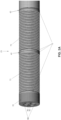
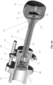
- Endoscope 5 generally comprises a shaft 10 having a distal end 15 and a proximal end 20. Shaft 10 is flexible in the articulating region 25 as will hereinafter be discussed in further detail. The proximal end 20 of shaft 10 is mounted to a handle 30.
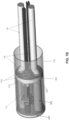
- a plurality of stacked spacer elements (e.g., rings) 55 are coaxially mounted on Nitinol superelastic wire 50 between distal joiner deck 35 and the at least one intermediate deck 40, and between the at least one intermediate deck 40 and base joiner deck 45, so as to ensure a fixed spacing between distal joiner deck 35 and the at least one intermediate deck 40, and between the at least one intermediate deck 40 and base joiner deck 45, regardless of endoscope articulation.
- actuating wires 60 are bonded securely within distal joiner deck 35 and slidably pass through the at least one intermediate deck 40 and base joiner deck 45.
- conduit tubes 65 joined to base joiner deck 45 and extending proximally therefrom, maintain straightness and proper orientation of actuating wires 60 as the actuating wires pass through the axial length of endoscope 5.
- two metal bellows 70 are hermetically joined (at joints 75) to their respective decks 35 and 40, and 40 and 45, providing rotational rigidity to endoscope 5 and hermetically sealing the elements within.
- Holes 80 in decks 35, 40 and 45 allow electronic leads 85 (see Fig. 3 ) to slide freely within decks 35, 40 and 45, and holes 90 in decks 35, 40 and 45 allow fiber optic illumination bundles 95 (see Fig. 3 ) to slide freely within decks 35, 40 and 45 during endoscope articulation.
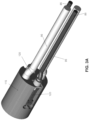
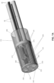
- Fig. 3 shows the sealed camera module 100 which is disposed in shaft 10 distal to distal joiner deck 35, with electronic leads 85 and fiber optic illumination bundles 95 passing through holes 80 and 90 within decks 35, 40 and 45.
- Sealed camera module 100 comprises an outer sleeve 105, an elastomer seal 110 and the aforementioned electronic leads 85 (from the camera module's image sensor assemblies, see below) and optical fiber illumination bundles 95.
- Figs. 3A , 3B and 3C show interior construction details of sealed camera module 100.
- Fig. 3A shows the module body 115 which is disposed coaxially within outer sleeve 105 of sealed camera module 100, and an image sensor assembly 120, as well as the aforementioned electronic leads 85 and fiber optic illumination bundles 95.
- Fig. 3C illustrates the interior elements of sealed camera module 100 aligned and bonded within module body 115. Shown are pairs of CCD image sensor assemblies 120, camera lens cells 125 and optical fiber illumination bundles 95 bonded and polished within ferrules 130.
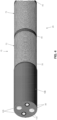
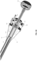
- Fig. 4 illustrates the assembled distal end 15 of endoscope 5, including articulating region 25.
- distal end of distal joiner deck 35 is received within outer sleeve 105 of sealed camera module 100, with the distal end of distal joiner deck 35 abutting elastomer seal 110 and with the outer sleeve 105 of sealed camera module 100 being hermetically bonded to the outside diameter of distal joiner deck 35.
- electronic leads 85 of image sensor assemblies 120 and fiber optic illumination bundles 95 extend through decks 35, 40 and 45, with metal bellows 70 cooperating with decks 35, 40 and 45 so as to render the distal end of shaft 10 hermetically sealed.
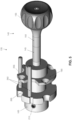
- Fig. 5 shows the endoscope's steering and brake assembly 135 which is contained within, and extends out of, handle 30.
- the user may direct the viewing angle of the endoscope by manipulating the control joystick 140, which comprises shaft members 145 and 150 and knob 155.
- the control joystick position also provides an external indication of the endoscope's viewing position, with the shaft (145, 150) of control joystick 140 representing the axis of a pointer and knob 155 representing the "tail" of the pointer.
- Control joystick 140 is secured by a captive ball joint 160 ( Fig. 5A ) formed by a base 165, a bearing ball 170 and a braking element 175. Viewing may be directed in a 360 degree conic arc of up to, but not limited to, an included angle of 140 degrees without altering the disposition of the main body of endoscope 5 itself.
- Fig. 1 shows the actual device with the viewing angle being held in place by the brake feature.
- Manipulating control joystick 140 deflects the distal end of the endoscope, whereby to appropriately direct its camera, by pulling one or more of the four actuating wires 60 ( Fig. 5D ) held in position within a swash plate 180 by four ball-ended terminations 185 ( Figs. 5D and 5E ) bonded or swaged to their respective Nitinol pull wires 60.
- Figs. 5A and 5E represent sectional views of the steering and brake assembly 135. When the desired view position is achieved, the brake is applied by rotating knob 155 clockwise.
- Knob 155 drives the brake cam 190 ( Fig. 5B ) through a drive pin 195.
- a Nitinol brake pull wire 200 ( Fig. 5A ) passes through a threaded tubular control joystick core 205 and is fixed within the braking element 175 by two non-scoring set screws 210 ( Fig. 5A ) .
- Nitinol (a superelastic nickel titanium alloy) is used for its high strength in brake pull wire 200 as well as in the aforementioned Nitinol superelastic wire 50 disposed within the distal end of the endoscope (see above). Nitinol's unique elastic properties resist fatigue and contribute to maintaining straightness when the brake is not engaged.
- Braking element 175 features a partial precision hemispherical socket covering approximately one third of the control stick precision bearing ball 170 ( Fig. 5A ). With the brake released, the braking element 175 serves as the distal element of the control stick bearing socket.
- the movable braking element 175 ( Fig. 5A ) is constrained by the main tube sleeve 215 ( Fig. 5E ).
- the Nitinol brake pull wire 200 ( Fig. 5A ) is attached to the cam follower body 220 ( Fig. 5A ) by two non-scoring set screws 225 (only one of which is shown in Fig. 5A ).
- Two cam follower pins 230 ( Fig. 5A ) are inserted through slots in the cam 235 ( Fig. 5A ) and restraining grooves 240 in the knob body 245 ( Fig. 5C ).
- Fig. 5A shows, at 250, the exit point of the hole through the threaded core 205 of control joystick 140 located at the center point of the bearing ball 170. This is done to minimize any effective length change caused by the excursion made by the control joystick during use. Minimizing this length change effect removes unwanted friction and/or, conversely, sudden accidental brake release.
- Undesirable rotation of the swash plate 180 is prohibited by a restraining tab 255 ( Figs. 5A and 5B ) which is disposed within a parallel pair of dowel pins 260 joined to base 165.
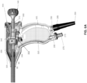
- Figs. 6 and 6A show the proximal hand control end of endoscope 5.
- Handle 30 may be gripped by the user and the control joystick 140 operated with the thumb of the gripping hand of the user, or the control joystick 140 may be operated with the other hand of the user.
- the fiber optic illumination bundles 95 are terminated and polished at 270 in an input connector 275 to which an input light guide (not shown) from the accessory light source (not shown) is connected.
- the electronic leads (cable) 85 ( Fig. 3 ) connect the image sensor assemblies 120 ( Fig. 3C ) to the main 3D video control unit (not shown) and are routed through (at 280) a suitable strain relief 285.
- Both the electronic cable strain relief 285 and the fiber optic input connector 275 are sealably bonded at 290, 295, respectively, to handle 30.
- Control joystick 140 is movably sealed to handle 30 by an elastomer seal 300 which is configured so as to minimize resistance to movement of control joystick 140.
- Area 305 of elastomer seal 300 is preferably made slightly undersized so as to grasp and seal to handle 30, and area 310 of elastomer seal 300 is preferably made slightly undersized so as to grasp and seal to control joystick 140. This sealing may be further augmented by adding compression collars and/or suitable adhesives to areas 305, 310.
- a stainless steel collar 315 provides additional support for the main tube 320 of shaft 10 where main tube 320 emerges from handle 30. Note that main tube 320 of shaft 10 is bonded and sealed to handle 30.
- Handle 30 may be formed from two halves which are united during manufacturing, e.g., by bonding at 325.
- Fig. 6A shows the proximal portion of endoscope 5 as it appears with the left side of handle 30 removed.
- the fiber optic illumination bundles 95 pass through the elongated hole 330 in outer tube 320 and then extend down to input connector 275.
- the shielded electronic leads 85 from the image sensor assemblies 120 also pass through the elongated hole 330 in outer tube 320 and then extend down to suitable strain relief 285.
- the flange 332 ( Figs. 5A and 6A ) of base 165 is retained and supported within matching receiving features 335 within each handle half.
- shaft 10 of endoscope 5 comprises a sealed camera module 100 ( Fig. 3 ) which has its distal working components (e.g., the image-forming optics and electronics shown in Figs. 3A , 3B and 3C ) disposed within outer sleeve 105 so as to present its objective lens cells 125 and the distal ends of its fiber optic illumination bundles 95 to the region distal to outer sleeve 105, with fiber optic illumination bundles 95 and electronic leads 85 extending proximally therefrom.
- Shaft 10 further comprises three decks 35, 40 and 45 ( Figs. 2 and 2A ) which are connected together by an interior wire spine 50 and exterior metal bellows 70 so as to provide an articulating region to the shaft.
- Wire spine 50 further comprises a plurality of stacked spacer elements (e.g., rings) 55 coaxially mounted on the wire spine 50 so as to ensure consistent shaft length when the shaft is articulated.
- Distal deck 35 is received within and mated to outer sleeve 105 of sealed camera module 100, and main tube 320 of shaft 10 extends proximally from proximal deck 45. The proximal end of main tube 320 is secured to handle 30.
- Actuating wires 60 are provided to articulate the distal end of shaft 10 and, to this end, the distal end of articulating wires 60 are secured to distal deck 35 and extend proximally along the shaft, terminating at swash plate 180 of the steering and brake assembly 135.
- swash plate 180 The disposition of swash plate 180, and hence the disposition of the distal end of shaft 10, is adjusted by manipulating knob 155 at the proximal end of steering and brake assembly 135.
- the disposition of swash plate 180, and hence the view position of the distal end of the shaft, is adjusted by moving control joystick 140, and is locked in position by turning knob 155 of control joystick 140, which applies a proximal force to brake pull wire 200, which causes brake 175 to lock bearing ball 170 in position, whereby to lock swash plate 180 (and hence the distal end of the shaft) in position.
- endoscope 5 is hand-operated. However, by linking at least two electromechanical, remotely-operated servos to at least two quadrants of the swash plate 180 and replacing handle 30 with a suitable adapter, steerable electronic stereoscopic endoscope 5 may be adapted for utilization with remotely-operated surgical robot systems.
- the steerable distal portion of the endoscope comprises metal bellows 70 soldered or welded to the metal decks 35, 40 and 45.
- prior art flexible or distally-steerable endoscopes include plastic steerable outer sheath portions that preclude attaining a fully autoclavable design.
- objective lens cells 125 may be designed in such a way that the distal optical lens or window is fabricated out of optical grade sapphire and soldered to the metal barrel of the lens cell. Note that this type of sapphire-to-metal sealing technology is well known in the art. The metal barrels of the camera lens cells 125 may then be welded to the module body 115 ( Fig. 3B ).
- each objective lens assembly 125 may be soldered directly to the module body 115.
- thin sapphire windows may be soldered to the module body 115 at the distal ports of illumination fibers 95, thereby providing for autoclavable hermetic seals at the distal surface of module body 115.
- the outer sleeve 105 ( Fig. 3 ) may be welded or brazed to module body 115 at its distal end.
- elastomer seal 110 may be replaced with a metal part welded or brazed to outer sleeve 105 and having hermetic feed-through connections for illumination fiber bundles 95 and image sensor cables 85.
- hermetic feed-through connectors are known in the art. The modifications described above will encapsulate the most critical distal portion of the endoscope, which contains the optics and image sensors, into a fully hermetic assembly amenable to multiple autoclave cycles. The remaining portions of the endoscope are much less critical for small amounts of moisture and may be sealed by conventional sealing methods using elastomers and adhesives.
- Figs. 7A and 7B show an alternative configuration of the camera head featuring improved resistance to degradation from steam autoclave sterilization.
- a distal stainless steel face (or deck) 345 features two holes 350 closely fitted with the conduit tubes 355 of illumination fibers 95.
- Conduit tubes 355 are sealably soldered about their distal perimeter to each hole 350.
- two sapphire optical windows 360 with metalized edges which are also sealably soldered in holes 365 in stainless steel face 345. These sapphire windows 360 are aligned with the optical axis of the two camera lens cells 125.
- a second stainless steel face (or deck) 370 constrains the proximal ends of the conduit tubes 355 of illumination fiber optics 95, i.e., conduit tubes 355 are sealably soldered in holes 375 in metal deck 370.
- the camera heads 120, and their corresponding lens cells 125, are constrained and held in proper alignment within module body 115 (shown transparent in Figs. 7A and 7B ) .
- This assembled camera module is adhesively bonded within the inner diameter of the outer sleeve 105.
- deck 370 also has two glass-to-metal sealed headers 380 ( Fig. 7B ) sealably soldered within holes 385 formed in deck 370.
- the electronic leads 85 from the two image sensor assemblies 120 are conductively joined to the glass-sealed feed-through leads within the two glass-to-metal sealed headers 380.
- the two illumination fiber bundles 95 are seen exiting their corresponding sealed conduits 355 in Fig. 7B .
- the two decks 345, 370 are sealably soldered within the inner diameter 385 of outer sleeve 105, resulting in an assembly sealed by solder about the perimeters of the fiber optic conduits 355, sapphire windows 360 and glass headers 380.
- Figs. 6 and 6A show two connections, i.e., connection 275 for the illumination fibers 95 and connection 285 for electrical cable 85.
- these two connectors may be combined into one universal cable carrying both illumination fibers and electrical wires, and may be permanently affixed to handle 30.
- the proximal end of such a universal cable connects to a universal control unit (not shown) comprising a light source and the camera processor.
- a universal cable may be detachably connected to handle 30.
- the proximal portion of the endoscope may contain an illumination engine based on white LEDs optically coupled to illumination fiber bundles 95 ( Fig. 3 ) .
- an external light source will be no longer needed.
- the electrical power and control signals for the LEDs may be supplied via connector 285.
- miniature white LEDs may be disposed at the distal end of the shaft of the endoscope, thereby eliminating illumination fiber bundles 95 altogether, or coupled to very short segments of illumination fiber.
- the proximal portion of the endoscope contains a portable electrical power supply (e.g., a battery) and a wireless transceiver for providing a wireless video link to a corresponding transceiver in the external camera control unit.
- a portable electrical power supply e.g., a battery
- a wireless transceiver for providing a wireless video link to a corresponding transceiver in the external camera control unit.
- the proximal portion of the endoscope contains the entire video processing circuitry using highly integrated SoC ("system-on-a-chip”) or CoC ("camera-on-a-chip”) electronics.
- SoC system-on-a-chip
- CoC camera-on-a-chip
- This embodiment if combined with the two embodiments previously described (i.e., on-board light source, portable power supply and wireless communications), will eliminate the need for an external light source, external camera processing unit, light guide and electrical cable.
- the wireless video link will be established directly with a wireless device built into a video display, or with a wireless device external to, and electrically coupled to, the video display.
Landscapes
- Health & Medical Sciences (AREA)
- Life Sciences & Earth Sciences (AREA)
- Surgery (AREA)
- Biomedical Technology (AREA)
- Medical Informatics (AREA)
- Optics & Photonics (AREA)
- Pathology (AREA)
- Radiology & Medical Imaging (AREA)
- Biophysics (AREA)
- Engineering & Computer Science (AREA)
- Physics & Mathematics (AREA)
- Heart & Thoracic Surgery (AREA)
- Nuclear Medicine, Radiotherapy & Molecular Imaging (AREA)
- Molecular Biology (AREA)
- Animal Behavior & Ethology (AREA)
- General Health & Medical Sciences (AREA)
- Public Health (AREA)
- Veterinary Medicine (AREA)
- Rehabilitation Therapy (AREA)
- Endoscopes (AREA)
- Instruments For Viewing The Inside Of Hollow Bodies (AREA)
Claims (5)
- Endoscope orientable (5) comprenant : un arbre (10) présentant une extrémité distale (15), une extrémité proximale (20) et une région d'articulation (25) entre les deux ; et une paire d'ensembles de capteurs d'images électroniques (120) alignés optiquement et liés de manière fixe à l'extrémité distale (15) de l'arbre (10) pour l'acquisition d'une image d'un site éloigné ;dans lequel l'arbre (10) comprend un tube principal (320), dans lequel l'extrémité proximale du tube principal (320) est fixée à une poignée (30) de l'endoscope orientable (5),caractérisée en ce que ;l'extrémité distale (15) de l'arbre (10) comprend un fil guide plein (50) présentant une extrémité distale (15) et une extrémité proximale (20), une première section (35) montée à l'extrémité distale du fil guide (50) et une deuxième section (45) montée à l'extrémité proximale du fil guide (50), et une pluralité d'éléments d'espacement empilés (55), chacun d'entre eux étant monté coaxialement sur le fil guide (50) entre la première section (35) et la deuxième section (45), l'endoscope orientable (5) comprenant, en outre, une troisième section (40) disposée entre la première section (35) et la deuxième section (45), et dans lequel, en outre, la troisième section (40) est montée de manière à coulisser sur le fil guide (50), dans lequel la pluralité d'éléments d'espacement empilés (55) est montée coaxialement sur le fil guide (50) entre la première section (35) et la troisième section (40), et entre la troisième section (40) et la deuxième section (45), dans lequel chacune de la première section (35), de la deuxième section (45) et de la troisième section (40) comprend un premier trou (80), qui permet aux fils électroniques (85) de glisser librement à l'intérieur des sections (35, 40, 45), et un second trou (90), qui permet aux fibres optiques (95) de glisser librement à l'intérieur des sections (35, 40, 45),dans lequel le tube principal (320) s'étend proximalement à partir de la troisième section (45).
- Endoscope orientable (5) selon la revendication 1, dans lequel la première section (35) et la troisième section (40) sont reliées de manière étanche par des soufflets métalliques flexibles (70), et dans lequel la deuxième section (45) et la troisième section (40) sont, en outre, reliées de manière étanche par des soufflets métalliques flexibles (70).
- Endoscope orientable (5) selon la revendication 1, comprenant, en outre, des faisceaux d'éclairage à fibres optiques (95) pour fournir de la lumière à l'extrémité distale (15) de l'arbre (10).
- Endoscope orientable (5) selon la revendication 1, comprenant, en outre, un ensemble de direction et de freinage (135) monté sur l'extrémité proximale (20) de 1 'arbre(10) pour contrôler la disposition de la partie de l'arbre (10) distale (15) par rapport à la région d'articulation (25) de l'arbre (10).
- Endoscope orientable (5) selon la revendication 1, dans lequel le fil guide (50) est composé de Nitinol.
Applications Claiming Priority (4)
| Application Number | Priority Date | Filing Date | Title |
|---|---|---|---|
| US201161550095P | 2011-10-21 | 2011-10-21 | |
| EP18165022.7A EP3372143B1 (fr) | 2011-10-21 | 2012-10-22 | Endoscope stéréoscopique électronique orientable |
| PCT/US2012/061375 WO2013059821A2 (fr) | 2011-10-21 | 2012-10-22 | Endoscope stéréoscopique électronique orientable |
| EP12842363.9A EP2768373B1 (fr) | 2011-10-21 | 2012-10-22 | Endoscope orientable comprenant un frein |
Related Parent Applications (3)
| Application Number | Title | Priority Date | Filing Date |
|---|---|---|---|
| EP12842363.9A Division EP2768373B1 (fr) | 2011-10-21 | 2012-10-22 | Endoscope orientable comprenant un frein |
| EP18165022.7A Division EP3372143B1 (fr) | 2011-10-21 | 2012-10-22 | Endoscope stéréoscopique électronique orientable |
| EP18165022.7A Division-Into EP3372143B1 (fr) | 2011-10-21 | 2012-10-22 | Endoscope stéréoscopique électronique orientable |
Publications (2)
| Publication Number | Publication Date |
|---|---|
| EP3666162A1 EP3666162A1 (fr) | 2020-06-17 |
| EP3666162B1 true EP3666162B1 (fr) | 2025-01-22 |
Family
ID=48136511
Family Applications (3)
| Application Number | Title | Priority Date | Filing Date |
|---|---|---|---|
| EP20154227.1A Active EP3666162B1 (fr) | 2011-10-21 | 2012-10-22 | Endoscope stéréoscopique électronique orientable |
| EP12842363.9A Active EP2768373B1 (fr) | 2011-10-21 | 2012-10-22 | Endoscope orientable comprenant un frein |
| EP18165022.7A Active EP3372143B1 (fr) | 2011-10-21 | 2012-10-22 | Endoscope stéréoscopique électronique orientable |
Family Applications After (2)
| Application Number | Title | Priority Date | Filing Date |
|---|---|---|---|
| EP12842363.9A Active EP2768373B1 (fr) | 2011-10-21 | 2012-10-22 | Endoscope orientable comprenant un frein |
| EP18165022.7A Active EP3372143B1 (fr) | 2011-10-21 | 2012-10-22 | Endoscope stéréoscopique électronique orientable |
Country Status (4)
| Country | Link |
|---|---|
| US (2) | US9044138B2 (fr) |
| EP (3) | EP3666162B1 (fr) |
| ES (2) | ES3013577T3 (fr) |
| WO (1) | WO2013059821A2 (fr) |
Families Citing this family (85)
| Publication number | Priority date | Publication date | Assignee | Title |
|---|---|---|---|---|
| US8556807B2 (en) | 2006-12-21 | 2013-10-15 | Intuitive Surgical Operations, Inc. | Hermetically sealed distal sensor endoscope |
| US8814779B2 (en) | 2006-12-21 | 2014-08-26 | Intuitive Surgical Operations, Inc. | Stereoscopic endoscope |
| US20130303944A1 (en) | 2012-05-14 | 2013-11-14 | Intuitive Surgical Operations, Inc. | Off-axis electromagnetic sensor |
| US10238837B2 (en) | 2011-10-14 | 2019-03-26 | Intuitive Surgical Operations, Inc. | Catheters with control modes for interchangeable probes |
| US9387048B2 (en) | 2011-10-14 | 2016-07-12 | Intuitive Surgical Operations, Inc. | Catheter sensor systems |
| US9452276B2 (en) | 2011-10-14 | 2016-09-27 | Intuitive Surgical Operations, Inc. | Catheter with removable vision probe |
| US20140148673A1 (en) | 2012-11-28 | 2014-05-29 | Hansen Medical, Inc. | Method of anchoring pullwire directly articulatable region in catheter |
| US20140221740A1 (en) * | 2013-02-05 | 2014-08-07 | Paul John Kawula | Wireless endoscopic surgical device |
| US20160278615A1 (en) * | 2013-02-05 | 2016-09-29 | Scopernicus, LLC | Wireless endoscopic surgical device |
| US11382492B2 (en) | 2013-02-05 | 2022-07-12 | Scopernicus, LLC | Wireless endoscopic surgical device |
| US20140275779A1 (en) * | 2013-03-12 | 2014-09-18 | Covidien Lp | Flexible Shaft with Multiple Flexible Portions |
| US20140360308A1 (en) * | 2013-06-10 | 2014-12-11 | Donal Walker Lumsden | Mechanical maneuvering system |
| DE102013110543A1 (de) * | 2013-09-24 | 2015-03-26 | Karl Storz Gmbh & Co. Kg | Vorrichtung zum Aufnehmen eines Bildes eines Objektfelds an einem menschlichen oder tierischen Körper |
| US9795279B2 (en) | 2013-10-21 | 2017-10-24 | Access Optics, LLC | Endoscope coupler |
| CN105939647B (zh) | 2013-10-24 | 2020-01-21 | 奥瑞斯健康公司 | 机器人辅助腔内外科手术系统及相关方法 |
| EP3075149A4 (fr) * | 2013-11-26 | 2017-07-19 | ConMed Corporation | Système de caméras stéréoscopiques utilisant une unité de commande monoscopique |
| EP2923669B1 (fr) | 2014-03-24 | 2017-06-28 | Hansen Medical, Inc. | Systèmes et dispositifs pour le guidage instinctif d'un cathéter |
| WO2015161061A1 (fr) | 2014-04-17 | 2015-10-22 | Stryker Corporation | Outil chirurgical à arbre sélectivement flexible, qui résiste à la déformation |
| JP5861017B1 (ja) * | 2014-08-11 | 2016-02-16 | オリンパス株式会社 | 内視鏡システム |
| US9737371B2 (en) | 2014-09-30 | 2017-08-22 | Auris Surgical Robotics, Inc. | Configurable robotic surgical system with virtual rail and flexible endoscope |
| CN107529958B (zh) * | 2014-10-20 | 2021-07-27 | 研发国际公司 | 可操纵微型内窥镜 |
| US10314463B2 (en) | 2014-10-24 | 2019-06-11 | Auris Health, Inc. | Automated endoscope calibration |
| WO2017079434A1 (fr) * | 2015-11-03 | 2017-05-11 | Nowlin John William | Stylet d'intubation guidable |
| US10143526B2 (en) | 2015-11-30 | 2018-12-04 | Auris Health, Inc. | Robot-assisted driving systems and methods |
| DE102015015993B4 (de) * | 2015-12-10 | 2019-05-29 | Schölly Fiberoptic GmbH | Endoskop |
| CN108463154B (zh) * | 2016-01-13 | 2021-02-26 | 奥林巴斯株式会社 | 内窥镜 |
| WO2017132265A1 (fr) | 2016-01-29 | 2017-08-03 | Boston Scientific Scimed, Inc. | Systèmes endoscopique et procédés associés |
| US11363944B2 (en) | 2016-02-12 | 2022-06-21 | Stryker Corporation | Surgical instrument with steerable camera |
| US20170239091A1 (en) * | 2016-02-22 | 2017-08-24 | Altek Corporation | Eardrum incision device |
| KR102429815B1 (ko) | 2016-04-14 | 2022-08-08 | 트랜스엔테릭스 서지컬, 인크. | 선형 구동식 기기 롤을 포함하는 전기기계 수술 시스템 |
| CN114587232B (zh) * | 2016-07-14 | 2025-12-19 | 直观外科手术操作公司 | 包含在手术器械的主体内的压力测试端口 |
| EP3484341B1 (fr) * | 2016-07-14 | 2023-03-08 | Intuitive Surgical Operations, Inc. | Endoscope comprenant une pluralité de sous-ensembles pouvant être testés individuellement |
| JP6234649B1 (ja) * | 2016-07-25 | 2017-11-22 | オリンパス株式会社 | 医療機器の湾曲操作機構 |
| WO2018020718A1 (fr) * | 2016-07-25 | 2018-02-01 | オリンパス株式会社 | Mécanisme de fonctionnement de flexion pour endoscope |
| JP6234650B1 (ja) * | 2016-07-25 | 2017-11-22 | オリンパス株式会社 | 内視鏡の湾曲操作機構 |
| CN109310275B (zh) * | 2016-07-25 | 2021-03-16 | 奥林巴斯株式会社 | 医疗器械的弯曲操作机构 |
| US9931025B1 (en) | 2016-09-30 | 2018-04-03 | Auris Surgical Robotics, Inc. | Automated calibration of endoscopes with pull wires |
| US10244926B2 (en) | 2016-12-28 | 2019-04-02 | Auris Health, Inc. | Detecting endolumenal buckling of flexible instruments |
| AU2018265018B2 (en) | 2017-05-12 | 2024-03-07 | Auris Health, Inc. | Biopsy apparatus and system |
| AU2018290831A1 (en) | 2017-06-28 | 2019-12-19 | Auris Health, Inc. | Instrument insertion compensation |
| WO2019003586A1 (fr) * | 2017-06-30 | 2019-01-03 | オリンパス株式会社 | Endoscope |
| US10426559B2 (en) | 2017-06-30 | 2019-10-01 | Auris Health, Inc. | Systems and methods for medical instrument compression compensation |
| WO2019003587A1 (fr) * | 2017-06-30 | 2019-01-03 | オリンパス株式会社 | Endoscope |
| US10145747B1 (en) | 2017-10-10 | 2018-12-04 | Auris Health, Inc. | Detection of undesirable forces on a surgical robotic arm |
| US10016900B1 (en) | 2017-10-10 | 2018-07-10 | Auris Health, Inc. | Surgical robotic arm admittance control |
| TWI659728B (zh) * | 2017-11-02 | 2019-05-21 | 國立交通大學 | 具末端轉向機構的微創手術用具 |
| CN110831536B (zh) | 2017-12-06 | 2021-09-07 | 奥瑞斯健康公司 | 用于针对非命令器械滚转进行校正的系统和方法 |
| JP7322026B2 (ja) | 2017-12-14 | 2023-08-07 | オーリス ヘルス インコーポレイテッド | 器具の位置推定のシステムおよび方法 |
| JP7301884B2 (ja) | 2018-02-13 | 2023-07-03 | オーリス ヘルス インコーポレイテッド | 医療用器具を駆動するためのシステム及び方法 |
| WO2019178180A1 (fr) * | 2018-03-13 | 2019-09-19 | Meditrina, Inc. | Endoscope et procédé d'utilisation |
| US10365554B1 (en) * | 2018-04-04 | 2019-07-30 | Intuitive Surgical Operations, Inc. | Dynamic aperture positioning for stereo endoscopic cameras |
| WO2019198350A1 (fr) * | 2018-04-13 | 2019-10-17 | オリンパス株式会社 | Endoscope chirurgical |
| DE102018209087A1 (de) * | 2018-06-07 | 2019-12-12 | Epflex Feinwerktechnik Gmbh | Bediengriffvorrichtung und Katheterinstrument |
| CN110393499B (zh) * | 2018-08-31 | 2021-12-07 | 上海微创医疗机器人(集团)股份有限公司 | 电子内窥镜及电子内窥镜系统 |
| CN119924988A (zh) | 2018-09-28 | 2025-05-06 | 奥瑞斯健康公司 | 用于伴随内窥镜和经皮医学规程的机器人系统和方法 |
| EP4643806A3 (fr) | 2018-09-28 | 2026-01-14 | Auris Health, Inc. | Systèmes et procédés d'accueil d'instruments médicaux |
| DE102018126938A1 (de) * | 2018-10-29 | 2020-04-30 | Hoya Corporation | Endoskopsteuervorrichtung und Endoskop mit einer Endoskopsteuervorrichtung |
| US11357593B2 (en) | 2019-01-10 | 2022-06-14 | Covidien Lp | Endoscopic imaging with augmented parallax |
| USD908161S1 (en) | 2019-01-15 | 2021-01-19 | Moleculight, Inc. | Handheld imaging device |
| USD910182S1 (en) | 2019-01-17 | 2021-02-09 | Sbi Alapharma Canada, Inc. | Handheld multi-modal imaging device |
| CA3127048A1 (fr) | 2019-01-17 | 2020-07-23 | Sbi Alapharma Canada, Inc. | Dispositifs, systemes, et methodes de visualisation et d'elimination de tumeur |
| USD908881S1 (en) | 2019-01-17 | 2021-01-26 | Sbi Alapharma Canada, Inc. | Handheld endoscopic imaging device |
| JP7648525B2 (ja) | 2019-01-17 | 2025-03-18 | モレキュライト・インコーポレイテッド | マルチモーダル撮像および解析のためのモジュールシステム |
| EP3911222A4 (fr) * | 2019-01-17 | 2023-02-01 | SBI Alapharma Canada, Inc. | Système endoscopique modulaire pour la visualisation d'une maladie |
| KR20210149102A (ko) * | 2019-04-08 | 2021-12-08 | 포티메딕스 에셋츠 Ii 비.브이. | 탈착가능한 부분을 포함하는 조향가능한 기구 |
| CN109924969A (zh) * | 2019-04-19 | 2019-06-25 | 优谱激光科技(南京)有限公司 | 一种具有轻便探头的激光成像血流灌注检测装置 |
| US11918187B2 (en) * | 2019-05-17 | 2024-03-05 | Boston Scientific Scimed, Inc. | Systems and devices for an endoscope tubeless working channel |
| CN110151109A (zh) * | 2019-05-23 | 2019-08-23 | 房博 | 一种多通道带有3d立体成像机构的软性内窥镜 |
| WO2020247386A1 (fr) | 2019-06-02 | 2020-12-10 | Wolf Technical Services, Inc. | Dispositif d'intubation d'introducteur de tube |
| DE102019115147C5 (de) * | 2019-06-05 | 2024-09-05 | Schott Ag | Biokompatibles Verbundelement und Verfahren zur Herstellung eines biokompatiblen Verbundelements |
| EP4084722A4 (fr) | 2019-12-31 | 2024-01-10 | Auris Health, Inc. | Interfaces d'alignement pour accès percutané |
| US11660147B2 (en) | 2019-12-31 | 2023-05-30 | Auris Health, Inc. | Alignment techniques for percutaneous access |
| CN119055360A (zh) | 2019-12-31 | 2024-12-03 | 奥瑞斯健康公司 | 解剖特征识别和瞄准 |
| DE102020104563A1 (de) | 2020-02-20 | 2021-08-26 | Christoph Miethke Gmbh & Co Kg | Vorrichtung zum Positionieren eines Herzimplantates |
| US11737663B2 (en) | 2020-03-30 | 2023-08-29 | Auris Health, Inc. | Target anatomical feature localization |
| US12011146B2 (en) | 2020-04-30 | 2024-06-18 | Ambu A/S | Method of assembly of an endoscope control system |
| US11259695B2 (en) | 2020-07-21 | 2022-03-01 | Meditrina, Inc. | Endoscope and method of use |
| EP4056100A1 (fr) | 2021-03-12 | 2022-09-14 | Ambu A/S | Partie de pointe pour dispositif de vision d'insertion médicale |
| DE102021119513A1 (de) | 2021-07-28 | 2023-02-02 | Karl Storz Se & Co. Kg | Verfahren zum Montieren einer Gelenkmechanik für ein medizinisches Instrument sowie Gelenkmechanik für ein medizinisches Instrument und medizinisches Instrument |
| DE102021119506A1 (de) | 2021-07-28 | 2023-02-02 | Karl Storz Se & Co. Kg | Verfahren zum Befestigen von Lenkelementen an einer räumlich verstellbaren Scheibe, Lenkelemente zum Bewegen einer distalseitigen Gelenkmechanik und medizinisches Instrument |
| DE102021119517A1 (de) | 2021-07-28 | 2023-02-02 | Karl Storz Se & Co. Kg | Verfahren zum Umformen und/oder zum Befestigen von Lenkdrähten an einer räumlich verstellbaren Scheibe, Lenkdrähten zum Bewegen einer distalseitigen Gelenkmechanik, medizinisches Instrument und Roboter |
| USD1117133S1 (en) | 2021-08-23 | 2026-03-10 | Moleculight Inc. | Modular handheld imaging device |
| CN114280767B (zh) * | 2021-12-27 | 2025-08-19 | 青岛奥美克医疗科技有限公司 | 双镜头同步调焦的三维图像适配器及内窥镜系统 |
| TWI837054B (zh) * | 2023-08-07 | 2024-03-21 | 醫電鼎眾股份有限公司 | 具有阻尼的內視鏡操縱桿 |
| US20260041316A1 (en) * | 2024-08-07 | 2026-02-12 | Cilag Gmbh International | Stereo chip-on-tip endoscope suitable for autoclave sterilization |
Citations (4)
| Publication number | Priority date | Publication date | Assignee | Title |
|---|---|---|---|---|
| US20030181785A1 (en) * | 2002-03-07 | 2003-09-25 | Thomas Viebach | Endoscope shaft comprising a movable end portion |
| US20070135803A1 (en) * | 2005-09-14 | 2007-06-14 | Amir Belson | Methods and apparatus for performing transluminal and other procedures |
| US20070276430A1 (en) * | 2006-05-23 | 2007-11-29 | Cambridge Endoscopic Devices, Inc. | Surgical instrument |
| US20090234186A1 (en) * | 2008-03-14 | 2009-09-17 | Chun-Ming Lin | Gastrointestinal endoscope with deflectable direction-change structure and deflectable direction-change tube thereof |
Family Cites Families (77)
| Publication number | Priority date | Publication date | Assignee | Title |
|---|---|---|---|---|
| US3788303A (en) * | 1972-01-24 | 1974-01-29 | American Cystoscope Makers Inc | Orthogonally deflectable endoscope |
| US4491865A (en) * | 1982-09-29 | 1985-01-01 | Welch Allyn, Inc. | Image sensor assembly |
| US4686963A (en) * | 1986-03-05 | 1987-08-18 | Circon Corporation | Torsion resistant vertebrated probe of simple construction |
| IT1235460B (it) * | 1987-07-31 | 1992-07-30 | Confida Spa | Endoscopio flessibile. |
| US4924852A (en) * | 1987-09-11 | 1990-05-15 | Olympus Optical Co., Ltd. | Endoscope |
| US5007406A (en) * | 1988-11-04 | 1991-04-16 | Asahi Kogaku Kogyo Kabushiki Kaisha | Bending control device of endoscope |
| DE3921233A1 (de) * | 1989-06-28 | 1991-02-14 | Storz Karl Gmbh & Co | Endoskop mit einer am distalen ende angeordneten videoeinrichtung |
| US5329887A (en) * | 1992-04-03 | 1994-07-19 | Vision Sciences, Incorporated | Endoscope control assembly with removable control knob/brake assembly |
| US5464007A (en) * | 1994-02-23 | 1995-11-07 | Welch Allyn, Inc. | Fluid insensitive braking for an endoscope |
| US5575755A (en) * | 1994-02-23 | 1996-11-19 | Welch Allyn, Inc. | Fluid insensitive braking for an endoscope |
| US5496260A (en) * | 1994-05-16 | 1996-03-05 | Welch Allyn, Inc. | Torque override knob for endoscopes, borescopes, or guide tubes |
| JPH0829701A (ja) * | 1994-07-18 | 1996-02-02 | Olympus Optical Co Ltd | 立体視内視鏡システム |
| EP0955860A1 (fr) * | 1995-06-07 | 1999-11-17 | Robert T. Chilcoat | Endoscope articule offrant des avantages specifiques en laryngoscopie |
| US5782752A (en) * | 1996-04-05 | 1998-07-21 | Vista Medical Technologies, Inc. | Device for carrying two units in end to end disposition and for moving one of the units alongside the other of the units |
| JP3526531B2 (ja) * | 1998-06-19 | 2004-05-17 | 富士写真光機株式会社 | 立体内視鏡の先端構造 |
| EP0978251B1 (fr) * | 1998-08-07 | 2005-01-26 | Olympus Corporation | Endoscope pouvant être passé à l'autoclave |
| US6080101A (en) | 1998-08-26 | 2000-06-27 | Olympus Optical Co. Ltd. | Endoscope video camera head which can be autoclaved |
| US7955340B2 (en) * | 1999-06-25 | 2011-06-07 | Usgi Medical, Inc. | Apparatus and methods for forming and securing gastrointestinal tissue folds |
| US6858005B2 (en) * | 2000-04-03 | 2005-02-22 | Neo Guide Systems, Inc. | Tendon-driven endoscope and methods of insertion |
| US6837846B2 (en) * | 2000-04-03 | 2005-01-04 | Neo Guide Systems, Inc. | Endoscope having a guide tube |
| EP2441394B1 (fr) * | 2000-11-28 | 2017-04-05 | Intuitive Surgical Operations, Inc. | Irrigateur pour un instrument endoscopique |
| JP2003153853A (ja) * | 2001-11-22 | 2003-05-27 | Olympus Optical Co Ltd | 内視鏡 |
| US7041052B2 (en) * | 2002-06-13 | 2006-05-09 | Usgi Medical Inc. | Shape lockable apparatus and method for advancing an instrument through unsupported anatomy |
| US20040193016A1 (en) * | 2002-06-17 | 2004-09-30 | Thomas Root | Endoscopic delivery system for the non-destructive testing and evaluation of remote flaws |
| EP1545289B1 (fr) * | 2002-09-30 | 2010-04-28 | Power Medical Interventions, LLC | Appareil chirurgical autonome sterilisable |
| US20040199052A1 (en) | 2003-04-01 | 2004-10-07 | Scimed Life Systems, Inc. | Endoscopic imaging system |
| US7090637B2 (en) * | 2003-05-23 | 2006-08-15 | Novare Surgical Systems, Inc. | Articulating mechanism for remote manipulation of a surgical or diagnostic tool |
| US8100824B2 (en) * | 2003-05-23 | 2012-01-24 | Intuitive Surgical Operations, Inc. | Tool with articulation lock |
| JP4460857B2 (ja) * | 2003-06-23 | 2010-05-12 | オリンパス株式会社 | 外科手術用システム |
| WO2005044124A1 (fr) * | 2003-10-30 | 2005-05-19 | Medical Cv, Inc. | Appareil et procede de traitement laser |
| DE10351013A1 (de) * | 2003-10-31 | 2005-06-02 | Polydiagnost Gmbh | Endoskop mit einer flexiblen Sonde |
| NL1025274C2 (nl) * | 2004-01-16 | 2005-07-19 | Univ Delft Tech | Instrument voor fijn-mechanische of fijn-chirurgische toepassingen. |
| JP4874259B2 (ja) * | 2004-11-23 | 2012-02-15 | ヌームアールエックス・インコーポレーテッド | 標的部位にアクセスするための操縦可能な装置 |
| US20060178562A1 (en) * | 2005-02-10 | 2006-08-10 | Usgi Medical Inc. | Apparatus and methods for obtaining endoluminal access with a steerable guide having a variable pivot |
| US20060252993A1 (en) * | 2005-03-23 | 2006-11-09 | Freed David I | Medical devices and systems |
| EP1886617A4 (fr) * | 2005-05-26 | 2010-09-29 | Ars Co Ltd | Endoscope |
| US8409175B2 (en) * | 2005-07-20 | 2013-04-02 | Woojin Lee | Surgical instrument guide device |
| JP4772464B2 (ja) * | 2005-11-11 | 2011-09-14 | オリンパスメディカルシステムズ株式会社 | 操作装置 |
| US20070112250A1 (en) * | 2005-11-16 | 2007-05-17 | Yasuhito Kura | Insertion support tool for medical instrument and insertion method for medical instrument |
| US9962066B2 (en) * | 2005-12-30 | 2018-05-08 | Intuitive Surgical Operations, Inc. | Methods and apparatus to shape flexible entry guides for minimally invasive surgery |
| US8617054B2 (en) * | 2006-01-13 | 2013-12-31 | Olympus Medical Systems Corp. | Medical treatment endoscope |
| US8021293B2 (en) * | 2006-01-13 | 2011-09-20 | Olympus Medical Systems Corp. | Medical treatment endoscope |
| US8556805B2 (en) * | 2006-01-13 | 2013-10-15 | Olympus Medical Systems Corp. | Rotational force transmission mechanism, force-attenuating apparatus, medical device, and medical instrument-operation mechanism |
| US8092371B2 (en) * | 2006-01-13 | 2012-01-10 | Olympus Medical Systems Corp. | Medical treatment endoscope |
| US20070225556A1 (en) * | 2006-03-23 | 2007-09-27 | Ethicon Endo-Surgery, Inc. | Disposable endoscope devices |
| US8721630B2 (en) * | 2006-03-23 | 2014-05-13 | Ethicon Endo-Surgery, Inc. | Methods and devices for controlling articulation |
| US20070225562A1 (en) * | 2006-03-23 | 2007-09-27 | Ethicon Endo-Surgery, Inc. | Articulating endoscopic accessory channel |
| JP5091229B2 (ja) * | 2006-04-24 | 2012-12-05 | シネコー・エルエルシー | 経管腔的外科手術システム |
| US9138250B2 (en) * | 2006-04-24 | 2015-09-22 | Ethicon Endo-Surgery, Inc. | Medical instrument handle and medical instrument having a handle |
| US8518024B2 (en) * | 2006-04-24 | 2013-08-27 | Transenterix, Inc. | System and method for multi-instrument surgical access using a single access port |
| US8029531B2 (en) * | 2006-07-11 | 2011-10-04 | Cambridge Endoscopic Devices, Inc. | Surgical instrument |
| US9084621B2 (en) * | 2006-12-01 | 2015-07-21 | Boston Scientific Scimed, Inc. | Guide tube systems and methods |
| US8556807B2 (en) * | 2006-12-21 | 2013-10-15 | Intuitive Surgical Operations, Inc. | Hermetically sealed distal sensor endoscope |
| WO2008095046A2 (fr) * | 2007-01-30 | 2008-08-07 | Loma Vista Medical, Inc., | Dispositif de navigation biologique |
| DE102007014739A1 (de) * | 2007-03-20 | 2008-09-25 | Karl Storz Gmbh & Co. Kg | Ablenkbares autoklavierbares Endoskop |
| US20080255420A1 (en) * | 2007-04-10 | 2008-10-16 | Cambridge Endoscopic Devices, Inc. | Surgical instrument |
| US20080262294A1 (en) * | 2007-04-20 | 2008-10-23 | Usgi Medical, Inc. | Endoscopic system with disposable sheath |
| US20080262300A1 (en) * | 2007-04-20 | 2008-10-23 | Usgi Medical, Inc. | Endoscopic system with disposable sheath |
| WO2008144077A1 (fr) * | 2007-05-18 | 2008-11-27 | Boston Scientific Scimed, Inc. | Systèmes de pilotage, et procédés d'utilisation |
| CA2684705A1 (fr) * | 2007-05-31 | 2008-12-11 | Boston Scientific Limited | Flexion active controlee dans des dispositifs medicaux |
| US7588176B2 (en) * | 2007-06-18 | 2009-09-15 | Ethicon Endo-Surgery, Inc. | Surgical cutting instrument with improved closure system |
| US8257386B2 (en) * | 2007-09-11 | 2012-09-04 | Cambridge Endoscopic Devices, Inc. | Surgical instrument |
| US20090076329A1 (en) | 2007-09-17 | 2009-03-19 | Wei Su | Disposable Stereoscopic Endoscope System |
| US20090171161A1 (en) * | 2007-12-10 | 2009-07-02 | Usgi Medical, Inc. | Steerable endoscopic instruments |
| US8460213B2 (en) * | 2008-01-03 | 2013-06-11 | Boston Scientific Scimed, Inc. | Cut tubular members for a medical device and methods for making and using the same |
| US10512392B2 (en) * | 2008-02-06 | 2019-12-24 | Intuitive Surgical Operations, Inc. | Segmented instrument having braking capabilities |
| US9055864B2 (en) * | 2008-04-02 | 2015-06-16 | Usgi Medical, Inc. | Endoscopic system with torque transmitting sheath |
| EP2278908B1 (fr) * | 2008-04-27 | 2021-06-02 | Loma Vista Medical, Inc. | Dispositif de navigation biologique |
| US8801752B2 (en) * | 2008-08-04 | 2014-08-12 | Covidien Lp | Articulating surgical device |
| US20110009694A1 (en) * | 2009-07-10 | 2011-01-13 | Schultz Eric E | Hand-held minimally dimensioned diagnostic device having integrated distal end visualization |
| US20110230723A1 (en) * | 2008-12-29 | 2011-09-22 | Salvatore Castro | Active Instrument Port System for Minimally-Invasive Surgical Procedures |
| US20100249497A1 (en) * | 2009-03-30 | 2010-09-30 | Peine William J | Surgical instrument |
| US20100286480A1 (en) * | 2009-05-06 | 2010-11-11 | Peine William J | Surgical instrument |
| US8363097B2 (en) * | 2009-07-23 | 2013-01-29 | Smith & Nephew, Inc. | Endoscopic imaging system |
| EP2533678B1 (fr) * | 2010-02-11 | 2020-03-25 | Intuitive Surgical Operations, Inc. | Système pour le maintien automatique d'une orientation de roulis sélectionnée par un opérateur au niveau d'une pointe distale d'un endoscope robotique |
| EP2563203B1 (fr) * | 2010-04-28 | 2016-10-26 | Viking Systems, Inc. | Coupleur stéréoscopique pour couplage mécanique et optique d'un stéréo-endoscope à une caméra stéréo-endoscopique |
| DE102010034378A1 (de) * | 2010-08-13 | 2012-02-16 | Karl Storz Gmbh & Co. Kg | Schaftelement für ein Endoskop |
-
2012
- 2012-10-22 EP EP20154227.1A patent/EP3666162B1/fr active Active
- 2012-10-22 EP EP12842363.9A patent/EP2768373B1/fr active Active
- 2012-10-22 EP EP18165022.7A patent/EP3372143B1/fr active Active
- 2012-10-22 ES ES20154227T patent/ES3013577T3/es active Active
- 2012-10-22 US US13/657,648 patent/US9044138B2/en active Active
- 2012-10-22 ES ES18165022T patent/ES2836119T3/es active Active
- 2012-10-22 WO PCT/US2012/061375 patent/WO2013059821A2/fr not_active Ceased
-
2015
- 2015-06-02 US US14/727,975 patent/US20160081529A1/en active Pending
Patent Citations (4)
| Publication number | Priority date | Publication date | Assignee | Title |
|---|---|---|---|---|
| US20030181785A1 (en) * | 2002-03-07 | 2003-09-25 | Thomas Viebach | Endoscope shaft comprising a movable end portion |
| US20070135803A1 (en) * | 2005-09-14 | 2007-06-14 | Amir Belson | Methods and apparatus for performing transluminal and other procedures |
| US20070276430A1 (en) * | 2006-05-23 | 2007-11-29 | Cambridge Endoscopic Devices, Inc. | Surgical instrument |
| US20090234186A1 (en) * | 2008-03-14 | 2009-09-17 | Chun-Ming Lin | Gastrointestinal endoscope with deflectable direction-change structure and deflectable direction-change tube thereof |
Also Published As
| Publication number | Publication date |
|---|---|
| WO2013059821A2 (fr) | 2013-04-25 |
| WO2013059821A3 (fr) | 2014-08-21 |
| EP3372143A1 (fr) | 2018-09-12 |
| ES2836119T3 (es) | 2021-06-24 |
| US20160081529A1 (en) | 2016-03-24 |
| EP3372143B1 (fr) | 2020-09-02 |
| EP3666162A1 (fr) | 2020-06-17 |
| EP2768373A2 (fr) | 2014-08-27 |
| US9044138B2 (en) | 2015-06-02 |
| US20130102846A1 (en) | 2013-04-25 |
| EP2768373A4 (fr) | 2016-02-17 |
| EP2768373B1 (fr) | 2018-06-13 |
| ES3013577T3 (en) | 2025-04-14 |
Similar Documents
| Publication | Publication Date | Title |
|---|---|---|
| EP3372143B1 (fr) | Endoscope stéréoscopique électronique orientable | |
| US12520998B2 (en) | Endoscopic surgical system | |
| EP3753473B1 (fr) | Endoscope vidéo et poignée, comprenant une limitation de rotation entraînée pour endoscope vidéo | |
| US11445890B2 (en) | Modular endoscope | |
| US8419623B2 (en) | Portable endoscope for diverse medical disciplines | |
| US9107573B2 (en) | Detachable shaft flexible endoscope | |
| US11911116B2 (en) | Virtual reality surgical camera system | |
| JP5562940B2 (ja) | 可視化システムを有する多関節装置 | |
| KR102569960B1 (ko) | 수술 로봇 시스템을 위한 기구 장치 조작기 | |
| US6398724B1 (en) | Focusable optical instrument with a sealed optical system having no internal optical moving parts | |
| EP3193694B1 (fr) | Endoscope articulé à usage unique, déployable dans un orifice | |
| US4611888A (en) | Coupler for surgical endoscope and video camera | |
| EP2883491B1 (fr) | Endoscope | |
| EP2412297A1 (fr) | Endoscope de type étui destiné à un traitement, et étui d'endoscope | |
| JP2020513288A (ja) | 分離可能使い捨てシャフト付き内視鏡 | |
| EP3484342B1 (fr) | Dispositif de capture d'image binoculaire compact | |
| US20250151991A1 (en) | Articulating medical devices and associated methods | |
| US20080058600A1 (en) | Method and system for stabilizing an optical imaging fiber in a diagnostic scope | |
| JPH0713087A (ja) | 硬性内視鏡装置 | |
| US20230148839A1 (en) | Disposable endoscope | |
| JP2015160078A (ja) | 内視鏡 | |
| US20240298883A1 (en) | Robotic surgical systems with dexterous endoscope | |
| JP2015178045A (ja) | 内視鏡 | |
| EP3761846B1 (fr) | Ampoule optique pour port d'instrument chirurgical | |
| WO2025072316A1 (fr) | Dispositifs médicaux et procédés associés |
Legal Events
| Date | Code | Title | Description |
|---|---|---|---|
| PUAI | Public reference made under article 153(3) epc to a published international application that has entered the european phase |
Free format text: ORIGINAL CODE: 0009012 |
|
| STAA | Information on the status of an ep patent application or granted ep patent |
Free format text: STATUS: THE APPLICATION HAS BEEN PUBLISHED |
|
| AC | Divisional application: reference to earlier application |
Ref document number: 2768373 Country of ref document: EP Kind code of ref document: P Ref document number: 3372143 Country of ref document: EP Kind code of ref document: P |
|
| AK | Designated contracting states |
Kind code of ref document: A1 Designated state(s): AL AT BE BG CH CY CZ DE DK EE ES FI FR GB GR HR HU IE IS IT LI LT LU LV MC MK MT NL NO PL PT RO RS SE SI SK SM TR |
|
| STAA | Information on the status of an ep patent application or granted ep patent |
Free format text: STATUS: REQUEST FOR EXAMINATION WAS MADE |
|
| STAA | Information on the status of an ep patent application or granted ep patent |
Free format text: STATUS: EXAMINATION IS IN PROGRESS |
|
| 17P | Request for examination filed |
Effective date: 20201126 |
|
| RBV | Designated contracting states (corrected) |
Designated state(s): AL AT BE BG CH CY CZ DE DK EE ES FI FR GB GR HR HU IE IS IT LI LT LU LV MC MK MT NL NO PL PT RO RS SE SI SK SM TR |
|
| 17Q | First examination report despatched |
Effective date: 20210113 |
|
| GRAP | Despatch of communication of intention to grant a patent |
Free format text: ORIGINAL CODE: EPIDOSNIGR1 |
|
| STAA | Information on the status of an ep patent application or granted ep patent |
Free format text: STATUS: GRANT OF PATENT IS INTENDED |
|
| INTG | Intention to grant announced |
Effective date: 20240828 |
|
| GRAS | Grant fee paid |
Free format text: ORIGINAL CODE: EPIDOSNIGR3 |
|
| GRAA | (expected) grant |
Free format text: ORIGINAL CODE: 0009210 |
|
| STAA | Information on the status of an ep patent application or granted ep patent |
Free format text: STATUS: THE PATENT HAS BEEN GRANTED |
|
| AC | Divisional application: reference to earlier application |
Ref document number: 2768373 Country of ref document: EP Kind code of ref document: P Ref document number: 3372143 Country of ref document: EP Kind code of ref document: P |
|
| AK | Designated contracting states |
Kind code of ref document: B1 Designated state(s): AL AT BE BG CH CY CZ DE DK EE ES FI FR GB GR HR HU IE IS IT LI LT LU LV MC MK MT NL NO PL PT RO RS SE SI SK SM TR |
|
| REG | Reference to a national code |
Ref country code: GB Ref legal event code: FG4D |
|
| REG | Reference to a national code |
Ref country code: CH Ref legal event code: EP |
|
| P01 | Opt-out of the competence of the unified patent court (upc) registered |
Free format text: CASE NUMBER: APP_43/2025 Effective date: 20250102 |
|
| REG | Reference to a national code |
Ref country code: IE Ref legal event code: FG4D |
|
| REG | Reference to a national code |
Ref country code: DE Ref legal event code: R096 Ref document number: 602012081335 Country of ref document: DE |
|
| REG | Reference to a national code |
Ref country code: ES Ref legal event code: FG2A Ref document number: 3013577 Country of ref document: ES Kind code of ref document: T3 Effective date: 20250414 |
|
| REG | Reference to a national code |
Ref country code: NL Ref legal event code: MP Effective date: 20250122 |
|
| PG25 | Lapsed in a contracting state [announced via postgrant information from national office to epo] |
Ref country code: NL Free format text: LAPSE BECAUSE OF FAILURE TO SUBMIT A TRANSLATION OF THE DESCRIPTION OR TO PAY THE FEE WITHIN THE PRESCRIBED TIME-LIMIT Effective date: 20250122 |
|
| PG25 | Lapsed in a contracting state [announced via postgrant information from national office to epo] |
Ref country code: RS Free format text: LAPSE BECAUSE OF FAILURE TO SUBMIT A TRANSLATION OF THE DESCRIPTION OR TO PAY THE FEE WITHIN THE PRESCRIBED TIME-LIMIT Effective date: 20250422 |
|
| PG25 | Lapsed in a contracting state [announced via postgrant information from national office to epo] |
Ref country code: FI Free format text: LAPSE BECAUSE OF FAILURE TO SUBMIT A TRANSLATION OF THE DESCRIPTION OR TO PAY THE FEE WITHIN THE PRESCRIBED TIME-LIMIT Effective date: 20250122 |
|
| PG25 | Lapsed in a contracting state [announced via postgrant information from national office to epo] |
Ref country code: PL Free format text: LAPSE BECAUSE OF FAILURE TO SUBMIT A TRANSLATION OF THE DESCRIPTION OR TO PAY THE FEE WITHIN THE PRESCRIBED TIME-LIMIT Effective date: 20250122 |
|
| REG | Reference to a national code |
Ref country code: LT Ref legal event code: MG9D |
|
| PG25 | Lapsed in a contracting state [announced via postgrant information from national office to epo] |
Ref country code: IS Free format text: LAPSE BECAUSE OF FAILURE TO SUBMIT A TRANSLATION OF THE DESCRIPTION OR TO PAY THE FEE WITHIN THE PRESCRIBED TIME-LIMIT Effective date: 20250522 Ref country code: NO Free format text: LAPSE BECAUSE OF FAILURE TO SUBMIT A TRANSLATION OF THE DESCRIPTION OR TO PAY THE FEE WITHIN THE PRESCRIBED TIME-LIMIT Effective date: 20250422 |
|
| REG | Reference to a national code |
Ref country code: AT Ref legal event code: MK05 Ref document number: 1760795 Country of ref document: AT Kind code of ref document: T Effective date: 20250122 |
|
| PG25 | Lapsed in a contracting state [announced via postgrant information from national office to epo] |
Ref country code: HR Free format text: LAPSE BECAUSE OF FAILURE TO SUBMIT A TRANSLATION OF THE DESCRIPTION OR TO PAY THE FEE WITHIN THE PRESCRIBED TIME-LIMIT Effective date: 20250122 |
|
| PG25 | Lapsed in a contracting state [announced via postgrant information from national office to epo] |
Ref country code: PT Free format text: LAPSE BECAUSE OF FAILURE TO SUBMIT A TRANSLATION OF THE DESCRIPTION OR TO PAY THE FEE WITHIN THE PRESCRIBED TIME-LIMIT Effective date: 20250522 Ref country code: LV Free format text: LAPSE BECAUSE OF FAILURE TO SUBMIT A TRANSLATION OF THE DESCRIPTION OR TO PAY THE FEE WITHIN THE PRESCRIBED TIME-LIMIT Effective date: 20250122 |
|
| PG25 | Lapsed in a contracting state [announced via postgrant information from national office to epo] |
Ref country code: BG Free format text: LAPSE BECAUSE OF FAILURE TO SUBMIT A TRANSLATION OF THE DESCRIPTION OR TO PAY THE FEE WITHIN THE PRESCRIBED TIME-LIMIT Effective date: 20250122 Ref country code: GR Free format text: LAPSE BECAUSE OF FAILURE TO SUBMIT A TRANSLATION OF THE DESCRIPTION OR TO PAY THE FEE WITHIN THE PRESCRIBED TIME-LIMIT Effective date: 20250423 |
|
| PG25 | Lapsed in a contracting state [announced via postgrant information from national office to epo] |
Ref country code: AT Free format text: LAPSE BECAUSE OF FAILURE TO SUBMIT A TRANSLATION OF THE DESCRIPTION OR TO PAY THE FEE WITHIN THE PRESCRIBED TIME-LIMIT Effective date: 20250122 |
|
| PG25 | Lapsed in a contracting state [announced via postgrant information from national office to epo] |
Ref country code: SE Free format text: LAPSE BECAUSE OF FAILURE TO SUBMIT A TRANSLATION OF THE DESCRIPTION OR TO PAY THE FEE WITHIN THE PRESCRIBED TIME-LIMIT Effective date: 20250122 |
|
| PG25 | Lapsed in a contracting state [announced via postgrant information from national office to epo] |
Ref country code: SM Free format text: LAPSE BECAUSE OF FAILURE TO SUBMIT A TRANSLATION OF THE DESCRIPTION OR TO PAY THE FEE WITHIN THE PRESCRIBED TIME-LIMIT Effective date: 20250122 |
|
| PG25 | Lapsed in a contracting state [announced via postgrant information from national office to epo] |
Ref country code: DK Free format text: LAPSE BECAUSE OF FAILURE TO SUBMIT A TRANSLATION OF THE DESCRIPTION OR TO PAY THE FEE WITHIN THE PRESCRIBED TIME-LIMIT Effective date: 20250122 |
|
| PGFP | Annual fee paid to national office [announced via postgrant information from national office to epo] |
Ref country code: IT Payment date: 20250926 Year of fee payment: 14 |
|
| PGFP | Annual fee paid to national office [announced via postgrant information from national office to epo] |
Ref country code: GB Payment date: 20250918 Year of fee payment: 14 |
|
| PGFP | Annual fee paid to national office [announced via postgrant information from national office to epo] |
Ref country code: FR Payment date: 20250922 Year of fee payment: 14 |
|
| PG25 | Lapsed in a contracting state [announced via postgrant information from national office to epo] |
Ref country code: EE Free format text: LAPSE BECAUSE OF FAILURE TO SUBMIT A TRANSLATION OF THE DESCRIPTION OR TO PAY THE FEE WITHIN THE PRESCRIBED TIME-LIMIT Effective date: 20250122 Ref country code: CZ Free format text: LAPSE BECAUSE OF FAILURE TO SUBMIT A TRANSLATION OF THE DESCRIPTION OR TO PAY THE FEE WITHIN THE PRESCRIBED TIME-LIMIT Effective date: 20250122 |
|
| REG | Reference to a national code |
Ref country code: DE Ref legal event code: R097 Ref document number: 602012081335 Country of ref document: DE |
|
| PG25 | Lapsed in a contracting state [announced via postgrant information from national office to epo] |
Ref country code: RO Free format text: LAPSE BECAUSE OF FAILURE TO SUBMIT A TRANSLATION OF THE DESCRIPTION OR TO PAY THE FEE WITHIN THE PRESCRIBED TIME-LIMIT Effective date: 20250122 |
|
| PG25 | Lapsed in a contracting state [announced via postgrant information from national office to epo] |
Ref country code: SK Free format text: LAPSE BECAUSE OF FAILURE TO SUBMIT A TRANSLATION OF THE DESCRIPTION OR TO PAY THE FEE WITHIN THE PRESCRIBED TIME-LIMIT Effective date: 20250122 |
|
| PLBE | No opposition filed within time limit |
Free format text: ORIGINAL CODE: 0009261 |
|
| STAA | Information on the status of an ep patent application or granted ep patent |
Free format text: STATUS: NO OPPOSITION FILED WITHIN TIME LIMIT |
|
| 26N | No opposition filed |
Effective date: 20251023 |
|
| PGFP | Annual fee paid to national office [announced via postgrant information from national office to epo] |
Ref country code: DE Payment date: 20250923 Year of fee payment: 14 |
|
| PGFP | Annual fee paid to national office [announced via postgrant information from national office to epo] |
Ref country code: ES Payment date: 20251106 Year of fee payment: 14 |