EP3666171B1 - Ensemble d'indexation de lentille - Google Patents
Ensemble d'indexation de lentille Download PDFInfo
- Publication number
- EP3666171B1 EP3666171B1 EP19215690.9A EP19215690A EP3666171B1 EP 3666171 B1 EP3666171 B1 EP 3666171B1 EP 19215690 A EP19215690 A EP 19215690A EP 3666171 B1 EP3666171 B1 EP 3666171B1
- Authority
- EP
- European Patent Office
- Prior art keywords
- lens
- holding portion
- rotating portion
- tactile
- holding
- Prior art date
- Legal status (The legal status is an assumption and is not a legal conclusion. Google has not performed a legal analysis and makes no representation as to the accuracy of the status listed.)
- Active
Links
Images


Classifications
-
- G—PHYSICS
- G02—OPTICS
- G02B—OPTICAL ELEMENTS, SYSTEMS OR APPARATUS
- G02B7/00—Mountings, adjusting means, or light-tight connections, for optical elements
- G02B7/02—Mountings, adjusting means, or light-tight connections, for optical elements for lenses
- G02B7/023—Mountings, adjusting means, or light-tight connections, for optical elements for lenses permitting adjustment
-
- A—HUMAN NECESSITIES
- A61—MEDICAL OR VETERINARY SCIENCE; HYGIENE
- A61F—FILTERS IMPLANTABLE INTO BLOOD VESSELS; PROSTHESES; DEVICES PROVIDING PATENCY TO, OR PREVENTING COLLAPSING OF, TUBULAR STRUCTURES OF THE BODY, e.g. STENTS; ORTHOPAEDIC, NURSING OR CONTRACEPTIVE DEVICES; FOMENTATION; TREATMENT OR PROTECTION OF EYES OR EARS; BANDAGES, DRESSINGS OR ABSORBENT PADS; FIRST-AID KITS
- A61F9/00—Methods or devices for treatment of the eyes; Devices for putting in contact-lenses; Devices to correct squinting; Apparatus to guide the blind; Protective devices for the eyes, carried on the body or in the hand
- A61F9/0061—Devices for putting-in contact lenses
-
- A—HUMAN NECESSITIES
- A61—MEDICAL OR VETERINARY SCIENCE; HYGIENE
- A61B—DIAGNOSIS; SURGERY; IDENTIFICATION
- A61B3/00—Apparatus for testing the eyes; Instruments for examining the eyes
- A61B3/10—Objective types, i.e. instruments for examining the eyes independent of the patients' perceptions or reactions
- A61B3/117—Objective types, i.e. instruments for examining the eyes independent of the patients' perceptions or reactions for examining the anterior chamber or the anterior chamber angle, e.g. gonioscopes
-
- G—PHYSICS
- G02—OPTICS
- G02C—SPECTACLES; SUNGLASSES OR GOGGLES INSOFAR AS THEY HAVE THE SAME FEATURES AS SPECTACLES; CONTACT LENSES
- G02C7/00—Optical parts
- G02C7/02—Lenses; Lens systems ; Methods of designing lenses
- G02C7/04—Contact lenses for the eyes
- G02C7/049—Contact lenses having special fitting or structural features achieved by special materials or material structures
Definitions
- a lens used in connection with gonioscopy i.e., the viewing of the periphery of the anterior chamber of the eye
- a gonio lens generally includes a contact lens element and one or more mirrors.
- the contact lens element has an optical axis and a concave contact surface that conforms to the anterior surface of the cornea of an eye.
- the contact lens element also has a viewing surface that is offset in an anterior direction from the contact surface.
- At least one mirror is arranged with its planar surface angled away from the optical axis of the contact lens element in an anterior direction. When the contact lens element is positioned on the eye, the mirrors reflect the light from the periphery of the anterior chamber of the eye into the direction of the observer, typically via a microscope for necessary magnification.
- a gonio lens allows an observer to visually assess inflammation or structural defects in the trabecular meshwork and related adjacent structures in the eye.
- a gonio lens can be configured for viewing and treating an eye, such as an iridotomy goniolaser lens and a trabeculoplasty goniolaser lens (e.g., a Selective Laser Trabeculoplasty lens or SLT lens).
- the observer may assess the trabecular meshwork before, during, and after the treatment with laser energy to thereby assess the efficacy of the treatment.
- the gonio lens may be used in surgery.
- Some lenses may include a plurality of mirrors, such as the Ocular Three Mirror Universal, manufactured by Ocular Instruments, Inc., of Bellevue, Washington, wherein the mirrors are circumferentially spaced respectively 120 degrees apart and are mounted at different angles of inclination. Each different mirror angle allows the user to inspect and evaluate different portions of the eye.
- Some lenses have a plurality of mirrors all having the same angle of inclination, such as the Ocular Posner Diagnostic and Surgical Gonio lens, also manufactured by Ocular Instruments, Inc., which can help reduce the need to rotate the mirror.
- a lens may include a single mirror, such as the Ocular Magna View Gonio, also manufactured by Ocular Instruments, Inc.
- a lens may include two mirrors, such as the Ahmed DVX direct view surgical gonio lens, also manufactured by Ocular Instruments, Inc., for an unreversed view, which is particularly helpful during surgical procedures.
- the selection and position of the specific mirror to be used during an evaluation will depend upon the portion of the eye that needs to be evaluated.
- the selected mirror is generally positioned opposite the area to be evaluated. For example, if the 12 o'clock position of the peripheral retina needs to be evaluated and a mirrored lens is being utilized, an angled mirror can be positioned at the 6 o'clock position of the retina so as to view the affected area.
- a multiple mirror lens or a single mirror lens it may be necessary to rotate the lens up to 360 degrees to examine the entire retina or other portions of the eye or to conduct a full treatment on the entire eye.
- DE 3 831 929 A1 discloses a mirror contact glass with a viewing surface for placing on the sclera of the human eye for examining peripheral fundus and vitreous body sections or the like, wherein a rotary part of a holder of the mirror contact glass has a riffle.
- US 8,861,061 B1 describes a lens assembly with a rotating member and a fixed member, wherein the fixed member comprises grooves to help the user grip the lens assembly.
- the task of providing an improved lens indexing assembly is solved by a lens indexing assembly according to claim 1 and a method of using a lens indexing assembly according to claim 12.
- Embodiments of the present disclosure are generally directed to indexing lens assemblies, and methods of indexing a rotating portion with lens relative to a holding portion, such as a contact lens or a gonio lens assembly used in optometry and ophthalmology.
- indexing refers to achieving precise rotation of a lens assembly in uniform increments. Each incremental rotated position is sometimes referred to as an "indexing position".
- an indexing position is achieved via tactile feedback in the form of surface contour alignment of a tactile feature of the rotating portion and lens with a tactile feature of the holding portion supporting the rotating portion.
- an indexing position may be achieved by tactile feedback in the form of a user understanding relative positioning of adjacent fingers on the user's hand.
- the rotating portion and the holding portion of the indexing lens assembly each include a plurality of tactile features on the exterior periphery to achieve an indexing position when the tactile features on the rotating portion become aligned with the tactile features on the holding portion.
- the indexing positions correspond to predetermined angular positions of the ophthalmic lens relative to a central axis through the indexing lens assembly.
- achieving alignment does not rely on sensing increased resistance to rotation or even visually sighting the alignment.
- Achieving an indexing position in accordance with the claimed invention is sensed through tactile feedback by the fingertips sensing when a tactile feature is in alignment with another tactile feature.
- resistance to rotation is the normal resistance that is inherent when a plain bearing surface of the rotating portion is in contact with a second plain bearing surface of the holding portion when the lens indexing assembly in in contact with an eye.
- the resistance to rotation is substantially constant at all angular positions of the ophthalmic contact lens, even at the indexing positions and from one indexing position toward another indexing position.
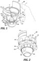
- the lens indexing assembly 100 in the illustrated embodiment includes a holding portion 102, a rotating portion 104 configured to rotate relative to the holding portion 102, and a lens 106 attached with the rotating portion 104 such that the rotating portion 104 and lens 106 rotate together as a unit.
- the rotating portion 104 rotates relative the holding portion 102 (as indicated by the arrow in FIGURE 1 ) to achieve indexing positions that help the user orient the positioning of the rotating portion 104 and lens 106 relative to the holding portion 102.
- the indexing positions of the illustrated embodiment are achieved when tactile features 108 on the rotating portion 104 are in alignment with tactile features 110 on the holding portion 102.
- the indexing positions are achieved when tactile features on the rotating portion are rotated by a finger on the hand of a user in reference to other fingers on the hand of a user, as described in greater detail below.
- the holding portion 102 is generally comprised of an annular body 120 defining inner and outer surfaces 122 and 124 and top 126 and bottom 128 axial surfaces.
- the annular body 120 defines an inner bore having a central axis 114 to permit viewing through the holding portion 102 to the lens 106 when the lens indexing assembly 100 is assembled.
- the central axis 114 generally aligns with the optical axis of the eye.
- the holding portion 102 includes holding tabs 112, which are configured for allowing a user to hold the holding portion 102 with a thumb T and index finger I (see FIGURE 1 ).
- the holding portion 102 and the holding tabs 112 are sized, designed, and configured for user comfort.
- the spacing between the holding tabs 112, allows for adequate light to enter the inner bore of the holding portion 102 to permit illumination through the holding portion 102 to the lens 106 when the lens indexing assembly 100 is assembled.
- the holding portion 102 may include a different holding configuration, for example, a continuous holding portion instead of holding tabs 112.
- the rotation portion 104 of the lens indexing assembly 100 is configured for rotational movement relative to the holding portion 102.
- the inner surface 122 of the holding portion 102 is a smooth surface having an even and regular surface substantially free from perceptible projections or indentations, and functions as a plain bearing surface when mated to the rotating portion 104.
- the outer surface 124 of the holding portion 102 includes a plurality of tactile features 110.
- the tactile features 110 are spaced evenly or uniformly around the outer surface 124 of the holding portion 102.
- other non-uniform spacing of the tactile features 110 is within the scope of the present disclosure.
- the outer surface 124 of the holding portion 102 can be considered to have an outer radius from the central axis 114 of the holding portion 102 in places where there is an absence of the tactile features 110.
- the tactile features 110 extend to a radius that can be different from the outer radius of the outer surface 124.
- each tactile feature 110 on the outer surface 124 can have the same arc length along the outer surface 124, and each tactile feature 110 can be spaced apart from the adjacent tactile features by a similar arc length.
- the arc length of the tactile features 110 extend from side edge 170 to side edge 170.
- the space on the outer surface 124 between the tactile features 110 can be considered to have the outer radius of the outer surface 124.
- the tactile features 110 extend axially at least to the lower outer edge between the outer surface 124 and a bottom axial surface 128 of the holding portion 102, but in this embodiment, do not need to extend axially to the upper edge between the outer surface 124 and a top axial surface 126 of the holding portion 102. Placing the tactile features 110 at least to the lower outer edge can help facilitate alignment with the tactile features 108 of the rotating portion 104.
- the tactile features 110 are indentations in the outer surface 124 of the holding portion 102. Therefore, the tactile features 110 extend to a radius less than the outer radius of the outer surface 124.
- the tactile features can be protrusions instead of indentations, for example, with the protrusions extending to a radius greater than the outer radius of the outer surface 124.
- the tactile features can be any surface contours, such as indentations or protrusions that differ with respect to radius from the outer radius of the outer surface 124.
- the tactile features 110 comprise indentations defined to receive the fingertip of a user. Such tactile features can be referred to as "fingertip grooves" because they are configured to accommodate the size and shape of an average finger.
- the tactile features 110 are rounded indentations extending between side edges 170 having a partial cylindrical shape and a partial spherical shape adjoined together.
- the tactile features 110 can be indentations having other shapes.
- the tactile features 110 can only comprise partial cylindrical shape and a partial spherical shape.
- the tactile features 110 do not require roundness, but can be square or rectangular shapes.
- the tactile features 110 can be V-shaped indentations.
- the lower axial surface 128 of the holding portion 102 functions as an axial plain bearing surface.
- the rotating portion 104 of the indexing lens assembly 100 is connected to the holding portion 102 such that an upper axial surface 152 of the rotating portion 104 is located adjacent the bottom axial surface 128 of the holding portion 102.
- the rotating portion 104 is generally comprised of an annular body 130 defining an inner bore having a central axis 114 to permit viewing through the lens 106 when the lens indexing assembly 100 is assembled.
- the central axis 114 of the rotating portion 104 is co-axial with the central axis 114 of the holding portion 102 when the lens indexing assembly 100 is assembly.
- the rotating portion 104 includes a first (top) section defining a coupling section 132 configured for coupling with the holding portion 102, a second (middle) section defining a tactile section 150 including tactile features 108 configured for aligning with the tactile features 110 on the holding portion 102, and a third (bottom) section defining a lens holding section 160 configured for holding a lens 106.
- the coupling section 132 of the rotation portion 104 is a cylindrical section including a plurality of partial cylindrical segments 134 and 138 extending from the annular body 130, all of similar inner and outer radiuses in a circular arrangement, configured for coupling the rotation portion 104 with the holding portion 102.
- First and second cylindrical segments 134 each have an outer surface 142 which functions as a radial plain bearing surface that is configured to rotate against the inner plain bearing surface 122 of the holding portion 102 when the rotation portion 104 and the holding portion 102 are coupled together.
- the outer surface 142 is of a slightly smaller radius than the inner surface 122 of the holding portion 102 to allow for coupling of the two portions 102 and 104.
- the first and second cylindrical segments 134 may be considered rigid or semi-rigid, while the third and fourth cylindrical segments 138 may be considered to be more flexible than the first and second segments 134.
- the first and second segments 134 make up a majority of the circumference in order to be rigid, while the third and fourth segments 138 make up a smaller portion of the total circumference, which allows the third and fourth segments 138 to flex relative to the first and second segments 134.
- the rigid and flexible segments may be made from the same material. In other embodiments, the rigid and flexible segments may be made from different materials to provide for a difference in flexibility.
- the first and second segments 134 are larger than the third and fourth segments 138.
- Recesses 136 between adjacent segments allow the third and fourth segments 138 to flex relative to the first and second segments 134.
- each flexible segment 138 may comprise a portion of the radial plain bearing surface 142. However, a function of the segments 138 is to keep the rotating portion 104 axially aligned with the holding portion 102 when two are coupled together.
- each flexible segment 138 includes an axial shank 144 and a radial barb 146.
- the axial shank 144 is slightly greater in the axial dimension than the axial dimension of the holding portion 102. This height difference allows the radial barb 146 to clear the holding portion 102 and come to rest on the axial upper surface 126 as seen in FIGURES 1 and 5 . Referring to FIGURE 3 again, the radial barb 146 extends out from the axial shank 144.
- the radial barb 146 has an underside surface that makes contact with the axial upper surface 126 of the holding portion 102 to keep the rotating portion 104 axially aligned within the holding portion 102.
- the axial upper surface 126 of the holding portion extends around the entirety of the annular wall 120 of the holding portion 102, allowing for 360 degree rotation of the rotation portion 104 relative to the holding portion 102.
- the flexible cylindrical segments 138 also render the rotating portion 104 separable from the holding portion 102.
- the flexible segments 138 can be depressed radially so that the radial barbs 146 clear the inner radius of the holding portion 102, and the rotating portion 104 is slipped into the holding portion 102 such that the plain bearing surface 142 of the rotating portion 104 is mated against the inner plain bearing surface 122 of the holding portion 102.
- a radial surface of the radial barbs 104 is in close proximity with the upper surface 126 of the holding portion 102.
- the radial barbs 104 can be depressed radially and the rotating portion 104 can be decoupled from the holding portion 102.
- the tactile features 108 of the tactile section 150 of the rotation portion 104 are positioned adjacent the tactile features 110 on the holding portion 102 and configured for alignment.
- the rotating portion 104 and holding portion 102 are separable from one another for cleaning and sterilization, for example, for ophthalmic examination or surgical procedures.
- the rotating portion 104 need not be removable from the holding portion 102.
- the rotating portion 104 may be configured without flexible cylindrical segments 138. In such configuration, the rotating portion 104 would be permanently rotatably coupled to the holding portion 102.
- the rotating portion 104 may optionally include a projection and groove system to maintain the rotating portion 104 on the holding portion 102, as described in U.S. Patent No. 6,183,085, issued to Roggy et al.
- the rotating portion 104 further includes a tactile section 150 including tactile features 108 configured for aligning with the tactile features 110 on the holding portion 102.
- a tactile section 150 including tactile features 108 configured for aligning with the tactile features 110 on the holding portion 102.
- the tactile features 108 of the rotating portion 104 are adjacent and can be aligned with the tactile features 110 on the holding portion 102 as the rotating portion 104 rotates relative to the holding portion 102. (See, for example, alignment of tactile features 108 and 110 in FIGURE 1 .)
- the tactile section 150 of the rotating portion 104 extends radially from the annular body 130 of the rotating portion 104.
- the tactile section 150 is the middle section of the rotating portion 104, between the coupling section 132 and the lens holding section 160.
- the tactile section 150 comprises part of the exterior periphery of the lens indexing assembly 100 as seen in FIGURES 1 and 2 , with the outer radius of the outer surface of the tactile section 150 being the same as the outer radius of the holding portion 102.
- the tactile features 108 are located around the exterior periphery of the tactile section 150.
- the tactile features 108 extend axially in the tactile section 150 at least to the upper axial surface 152 of the tactile section 150 of the rotating portion 104.
- the rotating portion 104 is connected to the holding portion 102 such that the upper axial surface 152 of the tactile section 150 is located adjacent the bottom axial surface 128 of the holding portion 102.
- This relationship between the tactile section 150 of the rotating portion 104 and the bottom axial surface 128 of the holding portion 102 places the tactile features 108 of the rotating portion 104 adjacent to the tactile features 110 of the holding portion 102. In this manner, the tactile features 108 on the tactile section 150 of the rotating portion 104 can be aligned with the tactile features 110 on the holding portion 102.
- the holding portion 102 When the holding portion 102 is coupled to the rotating portion 104, the upper axial surface 152 of the tactile section 150 of the rotating portion 104 is adjacent the bottom axial surface 128 of the holding portion 102 and acts as a plain bearing surface. Therefore, the holding portion 102 is coupled to the rotating portion 104 by being held between the radial barbs 138 of the coupling portion 132 of the rotating portion 104 and the upper axial surface 152 of the tactile section 150 of the rotating portion 104.
- the external bearing surface 142 of the coupling section 132 of the rotating portion 104 is in a bearing relationship with the interior bearing surface 122 of the holding portion 104. See FIGURES 5 and 6 .
- the upper axial surface 152 of the tactile section 150 of the rotating portion 104 supports the partial cylindrical segments 134 and 138 of the coupling section 132 of the rotating portion 104.
- the inner radius of the tactile section 150 can coincide with the inner radius of the coupling section 132.
- the tactile section 150 and the coupling section 132 can be formed as a single unit or can be separable.
- the outer surface 154 of the rotating portion 104 can be considered to have an outer radius from the central axis 114 of the rotating portion 104 in places where there is an absence of the tactile features 108.
- the tactile features 108 extend to a radius that can be different from the outer radius of the outer surface 154.
- each tactile feature 108 on the outer surface 154 can have the same arc length along the outer surface 154, and each tactile feature 108 can be spaced apart from the adjacent tactile features by a similar arc length.
- the space on the outer surface 154 between the tactile features 108 can be considered to have the outer radius of the outer surface 154.
- the tactile features 108 extend axially at least to the upper outer edge between the outer surface 154 and the upper axial surface 152 of the rotating portion 104, but, do not need to extend axially to the upper edge. Placing the tactile features 108 at least to the lower upper edge will facilitate alignment with the tactile features 110 of the holding portion 102.
- the tactile features 108 are indentations in the outer surface 154 of the rotating portion 104. Therefore, the tactile features 108 extend to a radius less than the outer radius of the outer surface 154. In other embodiments, the tactile features may be protrusions instead of indentations, for example, extending to a radius greater than the outer radius of the outer surface 154. In some embodiments, tactile features 108 can be any surface contours, such as indentations or protrusions that differ with respect to radius from the outer radius of the outer surface 154.
- the tactile features 108 comprise indentations defined to receive the fingertip of a user. Such tactile features can be referred to as "fingertip grooves" because they are configured to accommodate the size and shape of an average fingertip.
- the tactile features 108 are rounded indentations having a partial cylindrical shape.
- the tactile features 108 can be indentations having other shapes.
- the tactile features 108 can only comprise partial cylindrical shape and a partial spherical shape.
- the tactile features 108 do not require roundness, but can be square or rectangular shapes.
- the tactile features 108 can be V-shaped indentations.
- the rotating portion 104 further includes a holding section 160 configured to hold the lens 106.
- Suitable lenses for use in the lens indexing assembly 100 of the present disclosure include a variety of lenses.
- the lens 106 is a lens used in ophthalmology, including, but not limited to, a gonio lens.
- a gonio lens is especially suited to be used in the lens indexing assembly 100 because a gonio lens includes at least one mirror to reflect light depending on the direction the mirror is pointed.
- the lens indexing assembly 100 is particularly suited as a gonioscope to view the periphery of the anterior chamber of the eye.
- the lens 106 is an unreversed prism gonioscopy lens assembly designed to view the periphery of the anterior chamber angle A of the eye.
- the lens assembly 100 of the illustrated embodiment is a two-mirrored lens for an unreversed view.
- the holding section 160 is configured to hold the lens 106 with an interference fit such that the lens 106 can be held in place to rotate with the rotating portion 104 and such that the lens 106 may be removable from the rotating portion 104 for cleaning and sterilization.
- the holding section 160 includes a bezel ring 162 comprising a plurality of crenulations or segregated teeth 164 extending from the inner circumference of the rotating portion 104 (see FIGURES 5 and 6 ).
- the teeth 164 flex when the lens 106 is inserted such that the lens 106 can be held by a friction fit within the crenulations.
- the lens 106 may be replaceable.
- the lens 106 can be held in the bezel ring 162 through an adhesive.
- an inwardly extending stopping protrusion 174 keeps the lens 106 from being inserted past the holding section 160.
- the lens 106 is an unhoused lens. As can be seen in FIGURE 2 , the lens 106 protrudes from the rotating portion 104 to enable direct contact of the lens 106 with the eye of a patient.
- An unhoused lens 106 allows for more light to enter the lens from the side to enhance the viewing capabilities of the lens, as compared to light inhibited by a housing for receiving a lens.
- the lens 106 has a frustoconical shape.
- a suitable lens is shown and described in U.S. Patent No. 7,766,480 , issued to Graham al.
- Another nonlimiting example of a suitable lens is shown and described in U.S. Application Publication No. 2015/0313465 to Graham al.
- the lens may be an Ocular Magna View Gonio, manufactured by Ocular Instruments, Inc.
- Other non-limiting examples of lenses may include multiple mirror arrangements, such as the Ocular Three Mirror Universal, wherein the mirrors are circumferentially spaced respectively 120° apart and are mounted at different angles of inclination, for example, 59°, 67°, and 73° relative to the vertical, and the Ocular Posner Diagnostic and Surgical Gonioprism with a plurality of mirrors all having the same angle of inclination, both also manufactured by Ocular Instruments, Inc.
- the lens may be cylindrical in shape (see FIGURE 9 ).
- Tactile features 108 and 110 on the respective rotating and holding portions 104 and 102 can be sensed, such as through the fingertips.
- the tactile features 108 of the rotating portion 104 are designed to be alignable with the tactile features 110 of the holding portion 102 through touch and without relying on sight or visual recognition.
- the tactile features 108 of the rotating portion 104 are aligned with the tactile features 110 of the holding portion 102.
- tactile features 108 as indentations are aligned with tactile features 110 which are also indentations. Both indentations 108 and 110 have the same arc length.
- alignment can be judged to have occurred when a side edge 168 of indentation 108 is in line with a side edge 170 of indentation 110.
- the holding portion 102 and rotating portion 104 are aligned at one of the predefined indexing positions.
- the rotating portion 104 is rotated a small amount relative to the holding portion 102 so that the tactile features 108 of the rotating portion 104 are no longer in alignment with the tactile features 110 of the holding portion 102.
- the rotation of the rotating portion 104 can continue until a user senses that tactile features 108 of the rotating portion 104 are once again in alignment with the tactile features 110 of the holding portion 102.
- the user places the contact surface of the lens 106 on an eye of a patient.
- the user may grasp the holding portion 102 of the lens indexing assembly 100 between the thumb T and index finger I. Because the rotating portion 104 rotates relative to the rest of the holding portion 102, the user can then use the middle finger M on the same hand to rotate the rotating portion 104 and lens 106 while holding the holding portion 102 in a stationary position.
- the user can pull on the side edge 168 of a tactile feature 108 of the rotating portion 104 until the user senses through touch via the middle finger M that a tactile feature 108 of the rotating portion 104 is aligned with a tactile feature 110 of the holding portion 102 signifying that a predetermined indexing position has been reached.
- rotation of the lens 106 on the eye of the patient can be accomplished by the user with one hand.
- the user can rely on one indentation being aligned with another indentation. More specifically, a user may rely on the side edges which start and end at each indentation. For example, in FIGURE 1 , tactile feature 110 has a side edge 170 and tactile feature 108 has a side edge 168. Side edges 170 and 168 become collinear at the moment of alignment.
- the rotating portion 104 or the holding portion 102 can include a physical stop to prevent the rotation of the collar 104 beyond a certain point.
- the stop may indicate the 0 degree position in one direction and the 360 degree in the opposite direction. Rotation would not be possible beyond the stop, but rotation would be possible in the direction away from the stop.
- a plurality of indexing marks can be used for relative measurements of ocular structures.
- the rotating portion 104 is configured to index every 10 degrees and is used on a lens that has an embedded indicator, as described in U.S. Patent No. 7,766,480, issued to Graham et al. , the user would be able to estimate the angular size or arc length of ocular structures.
- the rotating portion 104 can be configured to index at four 90 degree angle locations to index with each of the different mirrors. Such indexing in this type of lens will save the user time in accurately rotating the lens to correspond with the desired mirror.
- FIGURES 7-12 another embodiment of a lens assembly 200 in accordance with the present disclosure is provided.
- the lens assembly of FIGURES 7-12 is similar in structure as well as function to the previously described lens assembly 100 of FIGURES 1-6 , but includes differences regarding the rotating portion 204 and the lens 206, as will be described.
- the lens assembly 200 in the illustrated embodiment includes a holding portion 202, a rotating portion 204 configured to rotate on the holding portion 202, and a lens 206 fixedly attached to the rotating portion 204 such that the rotating portion 204 and lens 206 rotate together as a unit.
- the rotating portion 204 is free to rotate on the holding portion 202 to achieve indexing positions that help the user orient the positioning of the rotating portion 204 and lens 206 relative to the holding portion 202. As described further below, the indexing positions are achieved when tactile features 208 on the rotating portion 204 are in alignment with tactile features 210 on the holding portion 202.
- the holding section 260 includes a crenulated bezel ring 262 comprising a plurality of crenulations or segregated teeth 264 extending from the inner circumference of the rotating portion 204.
- the lens 206 can be held by a friction fit within the crenulations.
- the lens 206 may be replaceable.
- the lens 06 can be held in the bezel ring 262 through an adhesive.
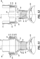
- FIGURES 13-18 another example of a lens assembly 300 which does not fall under the scope of the claimed invention.
- the lens assembly of FIGURES 13-18 is also similar in structure as well as function to the previously described lens assembly 100 of FIGURES 1-6 , but includes differences regarding the positioning of the holding portion and the rotating portion and differences regarding the tactile features, as will be described.
- the lens assembly 300 in the illustrated embodiment of FIGURES 13-18 includes a holding portion 302, a rotating portion 304 configured to rotate on the holding portion 302, and a lens 306 attached to the rotating portion 304 such that the rotating portion 304 and lens 306 rotate together as a unit.
- the rotating portion 304 is free to rotate relative to the holding portion 302 to achieve indexing positions that help the user orient the positioning of the rotating portion 304 and lens 306 relative to the holding portion 302.
- the rotating portion 304 is configured such that the index finger I of the user (rather than the middle finger M of the previously described embodiments) can be used to rotate the rotating portion 304.
- the tactile features 308 on the rotating portion 304 are configured for leverage in rotation and not necessarily for aligning with indentations on the holding portion 302.
- the indexing positions are achieved when tactile features 308 on the rotating portion 304 are rotated by a finger on the hand of a user in reference to holding fingers on the hand of a user, as described in greater detail below.
- the previously described embodiments may also be designed to incorporate the indexing configuration of the illustrated embodiment of FIGURES 13-18 .
- the rotating portion 304 includes a first (top) section defining a tactile section 350 including tactile features 308 configured for user rotation and indexing, a second (middle) section defining a coupling section 332 configured for coupling with the holding portion 302, and a third (bottom) section defining a lens holding section 360 configured for holding a lens 306.
- first and middle sections of the rotating portion 304 of the illustrated embodiment of FIGURES 13-18 are switched such that, when assembled, the tactile section 350 is located at the top end of the indexing lens assembly 300 above the holding potion 302.
- Such configuration of the rotating portion 304 allows the user to use his or her middle finger M and the thumb T to hold the holding portion 302 of the indexing lens assembly 300, and to use his or her index finger I to rotate the rotating portion 304 of the indexing lens assembly 300.
- the index finger is generally the most dexterous and sensitive of the fingers, and therefore, can be a better finger than the middle finger for some users for affecting rotation movement of the rotating portion 302 of the indexing lens assembly 300.
- the indexing finger is further spaced from the patient's head than the middle finger. Such spacing can aid in preventing accidental bumping of the moving finger affecting rotation movement of the rotating portion 302 with the patient's forehead or eye region.
- FIGURES 1-6 and 13-18 allow for user selection in rotation finger.
- the holding portion 302 is connected to the rotating portion 304 from the bottom end of the rotating portion 304.
- the holding portion 302 is generally comprised of an annular body 320 defining inner and outer surfaces 322 and 324 and top 326 and bottom 328 axial surfaces.
- the annular body 320 defines an inner bore having a central axis 314 to permit viewing through the holding portion 302 to the lens 306 when the lens indexing assembly 300 is assembled.
- the holding portion 302 of the illustrated embodiment further includes extended holding tabs 312 to allow the user to grip the holding portion, for example, with a thumb and middle finger, as shown in FIGURE 13 .
- the holding tabs 312 are spaced on the outer edge of the bottom axial surface 328 of the holding portion 302, so as not to interfere with the rotation of the rotation portion 304 relative to the holding portion 302, as described in greater detail below.
- the second (middle) section of the rotation portion 304 includes a coupling section 332 configured for coupling with the holding portion 302.
- the coupling section 332 of the rotation portion 304 is a cylindrical section including a plurality of partial cylindrical segments 334 and 338 extending from the annular body 330, all of similar inner and outer radiuses in a circular arrangement, configured for coupling the rotation portion 304 with the holding portion 302.
- First and second cylindrical segments 334 and 338 each have an outer surface 342 which functions as a radial plain bearing surface that is configured to rotate against the inner plain bearing surface 322 of the holding portion 302 when the rotation portion 304 and the holding portion 302 are coupled together.
- the outer surface 342 is of a slightly smaller radius than the inner surface 322 of the holding portion 302 to allow for coupling of the two portions 302 and 304 (see FIGURES 17 and 18 ).
- the first and second cylindrical segments 334 may be considered rigid or semi-rigid, while the third and fourth cylindrical segments 338 may be considered to be more flexible than the first and second segments 334.
- the first and second segments 334 make up a majority of the circumference in order to be rigid, while the third and fourth segments 338 make up a smaller portion of the total circumference, which allows the third and fourth segments 338 to flex relative to the first and second segments 334.
- the first and second segments 334 are larger than the third and fourth segments 338. Recesses 336 between adjacent segments allow the third and fourth segments 338 to flex relative to the first and second segments 334.
- the rigid and flexible segments may be made from the same material. In other embodiments, the rigid and flexible segments may be made from different materials to provide for a difference in flexibility.
- each flexible segment 338 makes up a portion of the radial plain bearing surface 342 (see FIGURE 15 ). However, a function of the segments 338 is to keep the rotating portion 304 axially aligned with the holding portion 302 when two are coupled together.
- each flexible segment 338 includes an outwardly extending radial barb 346.
- the radial barb 346 has an upper surface 356 that makes contact with the bottom axial surface 328 of the holding portion 302 to keep the rotating portion 304 axially aligned within the holding portion 302.
- the bottom axial surface 328 of the holding portion 302 in the illustrated embodiment extends around a portion of the annular wall 320 of the holding portion 302, allowing for 360 degree rotation of the rotation portion 304 relative to the holding portion 302.
- the holding portion 302 may designed for other rotation parameters up to 360 degree rotation.
- the holding tabs 312 of the holding portion 302 could be designed to limit rotation of the rotating portion 304 relative to the holding portion 302 within certain rotation limits, such as 90 degree rotation.
- the flexible cylindrical segments 338 also render the rotating portion 304 separable from the holding portion 302.
- the flexible segments 338 can be depressed radially so that the radial barbs 346 clear the inner radius of the inner wall surface 322 of the holding portion 302.
- the holding portion 302 is slipped onto the rotating portion 304 such that the plain bearing surface 342 of the rotating portion 304 is mated against the inner plain bearing surface 322 of the holding portion 302.
- a top radial surface of the radial barbs 346 is in close proximity with the bottom axial surface 328 of the holding portion 302 (see FIGURE 14 ).
- the radial barbs 346 can be depressed radially and the rotating portion 304 can be decoupled from the holding portion 302.
- the holding section 360 is configured to hold the lens 306 with an interference fit such that the lens 306 can be held in place to rotate with the rotating portion 304 and such that the lens 306 may be removable from the rotating portion 304 for cleaning and sterilization.
- the holding section 360 includes a bezel ring 362 comprising a plurality of crenulations or segregated teeth 364 extending from the inner circumference of the rotating portion 304 (see FIGURES 17 and 18 ), similar to previously described embodiments.
- the teeth 364 flex when the lens 306 is inserted such that the lens 306 can be held by a friction fit within the crenulations.
- the ends of the flexible segments 338 are a part of the teeth 364 of the lens holding portion 360.
- an inwardly extending stopping protrusion 374 keeps the lens 306 from being inserted past the holding section 360.
- the holding portion 302 does not include tactile features defining indentations.
- the rotating portion 304 includes tactile features 308 on the outer surface of the rotating portion 304.
- indexing in the illustrated embodiment of FIGURES 13-18 is achieved by the user's knowledge of a starting position with his or her moving finger and knowing the new position on the moving finger. Indexing also may be achieved by the user's knowledge of a starting position with his or her moving finger and a subsequent visual position of the user's moving finger on the circumference of the eye. For example, the user may start with the index finger I at a 12 o'clock position, the middle finger M adjacent the index finger I, also at a 12 o'clock position, and the thumb at a 6 o'clock position. The user's middle finger M and thumb T remain in the same positions on the holding portion 302. However, the user may move the index finger I and the rotating portion 304 from the 12 o'clock position to a 2 o'clock position to adjust the view of the patient's eye.
- Indexing is understood by the user feeling the new relative positioning of the index finger I relative to the middle finger M and/or by visual inspection of the relative positioning of the index finger I relative to the middle finger M.
- both the holding portion 302 and the rotating portion 304 include optional knurled sections to improve the user's grip on the lens assembly 300.
- Such knurled sections may be combined with smooth surfaces to improve grip, as seen in the illustrated embodiment.
- other sections may be knurled based on ergonomic design.
- the tactile features 308 on the rotating portion 304 provide leverage for the rotating finger.
- the tactile features 308 on the rotating portion 304 are shown as indentations on the outer surface of the rotating portion 304.
- Each tactile feature 308 has side edges 368 on either side of each of the indentations. Depending on the direction of rotation, the user can pull or push on these side edges 368 to effect rotation of the rotating portion 304 relative to the holding portion 302.
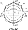
- FIGURES 19-24 another example of a lens assembly 500 which does not fall under the scope of the claimed invention.
- the lens assembly of FIGURES 19-24 is in many respects similar in structure as well as functions to the previously described lens assembly 300 of FIGURES 13-18 , but includes differences regarding the tactile features, as will be described.
- the holding portion 502 of the lens assembly 500 includes at least one tactile feature 510, which allows the user to orient the position of the rotation portion 504 of the lens assembly 500 with the tactile feature 510. For example, if the user is rotating the rotating portion 504 forward to a certain position at a certain degree of rotation, then the user wants to return to the original position, the user can use the at least one tactile feature 510 on the holding portion 502 to return the rotating portion 504 to an original position.
- the tactile section 550 of the rotating portion 504 in the illustrated embodiment of FIGURES 19-24 has a smaller height profile as compared to the embodiment of FIGURES 13-18 , allowing for a more compact design.
- the tactile section 550 is spaced from the holding portion by distance d (see FIGURE 23 ), the tactile features on the rotating portion are configured to be of a different cross-sectional shape, and the sizing of the indexing lens assembly is different, all to improve the ergonomic design for a specific user.
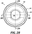
- the lens 606 of the illustrated embodiment of FIGURES 25-30 is the same as the lens 206 in FIGURES 7-12 . Because the lens 606 in the illustrated embodiment of FIGURES 25-30 is smaller than the lens 506 of FIGURES 19-24 , having a smaller diameter and smaller viewing end, the holding section 660 of the rotating portion 604 is configured to hold a smaller lens 606.
- a plurality of radial struts 672 extend radially from the inner surface of the holding section 660 to support a holding ring 674.
- the holding ring 674 supports the crenulated bezel ring 662 comprising a plurality of crenulations or segregated teeth 664.
- the teeth 664 flex when the lens is inserted such that the lens 606 can be held by a friction fit within the teeth 664. Spacing 676 between the adjacent radial struts 672 allows for light to travel from through the center bore of the lens indexing assembly 600 to aid in illumination of the eye.
- the ends of the flexible segments 638 are not part of the teeth 664 of the lens holding section 660. Instead the flexible segments 638 extend in the spacing 676 between the adjacent radial struts 672 of the lens holding section 660.
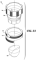
- FIGURES 31-33 another embodiment of a lens assembly 700 in accordance with the present disclosure is provided.
- the lens assembly of FIGURES 31-33 is in many respects similar in structure as well as functions to the previously described lens assembly 300 of FIGURES 13-15 , but includes differences regarding the tactile features, as will be described.
- the holding portion 302 does not include tactile features defining indentations; only the rotating portion 304 includes tactile features 308 on the outer surface of the rotating portion 304.
- the holding portion 702 of the lens assembly 700 includes a tactile feature 710 for mating with the tactile features 708 of the rotating portion.
- the tactile features 710 of the illustrated embodiment comprise indentations defined to receive the fingertip of a user. Such tactile features can be referred to as "fingertip grooves" because they are configured to accommodate the size and shape of an average finger.
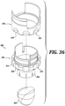
- FIGURES 34-37 another embodiment of a lens assembly 800 in accordance with the present disclosure is provided.
- the lens assembly of FIGURES 34-37 is similar in structure as well as function to the previously described lens assemblies, including lens assembly 100 of FIGURES 1-6 , but includes differences regarding the rotating portion 804, as will be described. It will be appreciated that the rotating portion 804, or features thereof, can be employed with any embodiment described herein.
- the lens assembly 800 in the illustrated embodiment includes a holding portion 802, a rotating portion 804 configured to rotate on the holding portion 802, and a lens 806 fixedly attached to the rotating portion 804 such that the rotating portion 804 and lens 806 rotate together as a unit.
- the rotating portion 804 is free to rotate on the holding portion 802 to achieve one or more positions, such as indexing positions, that help the user orient the positioning of the rotating portion 804 and lens 806 relative to the holding portion 802.
- the indexing positions are achieved, for example, when tactile features 808 on the rotating portion 804 are in alignment with tactile features 810 on the holding portion 802.
- the rotating portion 804 includes a first (top) section defining a coupling section configured for coupling with the holding portion 802, a second (middle) section defining a tactile section 850 including tactile features 808 configured for aligning with the tactile features 810 on the holding portion 802, and a third (bottom) section defining a lens holding section 860 configured for holding a lens 806.
- the holding section 860 of the holding portion 804 of FIGURES 34-37 is configured to hold the lens 806 with an interference fit such that the lens 806 can be held in place to rotate with the rotating portion 804 and such that the lens 806 may be removable from the rotating portion 804 for cleaning and sterilization.
- the lens 806 can be held by a friction fit.
- the lens 806 may be replaceable.
- the lens 806 can be held via an adhesive.
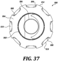
- the tactile features 808 are indentations in the outer surface 854 of the rotating portion 804.
- tactile features 808 can be any surface contours, such as indentations, that differ with respect to radius from the outer radius of the outer surface 854.
- the tactile features 808 comprise indentations defined to receive the fingertip of a user.
- the tactile features 808 have U-shaped (e.g., slightly rounded in some embodiments) indentations.
- the U-shape of the indentations is pronounced, such that the indentations are substantially similar to a square or rectangle (with an open top for receiving part of the fingertip) or identical to a square or rectangle.
- the indentations are formed as outwardly facing, U-shaped channels, each having a bottom wall and two side walls.
- the tactile features 808 can be square or rectangular shaped channels but with small rounded fillets at the intersections between the bottom wall and the side walls of the channel.
- each side wall extends slightly inwardly (toward the radial centerline of the channel (e.g., indentation)) into the channel at its outer end (adjacent the intersection with outer surface 854) so as to form a slight overhang 890, as shown in FIGURE 37 .
- the overhang improves the grip and/or leverage between the rotating portion 804 and the fingertip, thereby providing more precise control to the user.
- the side walls are parallel to each other.
- the side walls are parallel to each other and form right angles with the bottom wall of the channel.
- the tactile features 808 can be indentations or channels having other shapes.
Landscapes
- Health & Medical Sciences (AREA)
- Life Sciences & Earth Sciences (AREA)
- Physics & Mathematics (AREA)
- General Health & Medical Sciences (AREA)
- Public Health (AREA)
- Engineering & Computer Science (AREA)
- Biomedical Technology (AREA)
- Heart & Thoracic Surgery (AREA)
- Veterinary Medicine (AREA)
- Ophthalmology & Optometry (AREA)
- Animal Behavior & Ethology (AREA)
- Vascular Medicine (AREA)
- Surgery (AREA)
- Biophysics (AREA)
- Molecular Biology (AREA)
- Medical Informatics (AREA)
- General Physics & Mathematics (AREA)
- Optics & Photonics (AREA)
- Prostheses (AREA)
Claims (12)
- Ensemble d'indexage de lentille (100), comprenant une partie de maintien (102) et une partie rotative (104),la partie de maintien (102) étant réalisée de manière à porter la partie rotative (104), la partie de maintien (102) présentant une surface extérieure (124) réalisée pour le maintien et une surface de support (122) ;la partie rotative (104) étant réalisée pour le couplage à la partie de maintien (102), la partie rotative (104) étant réalisée de manière à tourner par rapport à la partie de maintien (102), et la partie rotative (104) présentant une surface de support (142) pour tourner par rapport à la surface de support (122) de la partie de maintien (102), la partie rotative (104) présentant une interface pour le couplage à une lentille de contact ophtalmique (106) ;caractérisé en ce quela partie de maintien (102) présente une pluralité de caractéristiques tactiles (110) sur la surface extérieure (124) de la partie de maintien (102), la pluralité de caractéristiques tactiles (110) de la partie de maintien (102) présentant une pluralité de creux de bout de doigt ou une pluralité de saillies de bout de doigt ;la partie rotative (104) présentant une pluralité de caractéristiques tactiles (108) sur une surface extérieure (142, 154), la pluralité de caractéristiques tactiles (108) de la partie rotative (104) présentant une pluralité de creux de bout de doigt ou une pluralité de saillies de bout de doigt,et au moins l'une parmi la pluralité de caractéristiques tactiles (108) sur la surface extérieure (142, 154) de la partie rotative (104) étant réalisée de manière à s'aligner sur la pluralité de caractéristiques tactiles (110) sur la partie de maintien (102) lors de la rotation de la partie rotative (104) par rapport à la partie de maintien (102) pour fournir une réaction tactile correspondant à une pluralité de positions angulaires de la lentille de contact ophtalmique (106) par rapport à la partie de maintien (102).
- Ensemble selon la revendication précédente, comprenant en outre une lentille de contact ophtalmique (106) réalisée pour le couplage à la partie rotative (104).
- Ensemble selon l'une des revendications précédentes, dans lequel la surface extérieure (124) de la partie de maintien (102) ou la surface de support (142) présente une pluralité de segments (134) avec des évidements (136) entre les segments (134) ; les segments (134) étant aptes à être enfoncés pour coupler et découpler la partie rotative (104) et la partie de maintien (102).
- Ensemble selon l'une des revendications précédentes, dans lequel les plusieurs caractéristiques tactiles (108) sur la surface extérieure (142, 154) de la partie rotative (104) sont des creux de bout de doigt sur la surface de la partie rotative (104).
- Ensemble selon la revendication 4, dans lequel chaque creux de bout de doigt présente une forme en U.
- Ensemble selon l'une des revendications précédentes, dans lequel chacune parmi la pluralité de caractéristiques tactiles (108) sur la surface extérieure (142, 154) de la partie rotative (104) est réalisée de manière à pouvoir être alignée sur au moins une caractéristique tactile (110) parmi la pluralité de caractéristiques tactiles (110) sur la surface extérieure (124) de la partie de maintien (102).
- Ensemble selon l'une des revendications précédentes, dans lequel au moins une caractéristique tactile (110) parmi la pluralité de caractéristiques tactiles (110) sur la surface extérieure (124) de la partie de maintien (110) est réalisée de manière à s'aligner sur la pluralité de caractéristiques tactiles (108) sur la surface extérieure (142, 154) de la partie rotative (104) pour fournir une réaction tactile correspondant à une pluralité de positions angulaires de la lentille de contact ophtalmique (106).
- Ensemble selon l'une des revendications précédentes, dans lequel ladite au moins une caractéristique tactile (108) parmi la pluralité de caractéristiques tactiles (108) sur la surface extérieure (142, 154) de la partie rotative (104) est réalisée de manière à s'aligner sur la pluralité de caractéristiques tactiles (110) sur la surface extérieure (124) de la partie de maintien (102) pour fournir une réaction tactile correspondant à au moins une position d'indexage.
- Ensemble selon l'une des revendications précédentes, dans lequel une résistance à une rotation de la partie rotative (104) est fournie par un contact par frottement entre la partie de maintien (102) et la partie rotative (104), la résistance à la rotation étant sensiblement constante pour l'ensemble des positions parmi la pluralité de positions angulaires de la lentille de contact ophtalmique (106).
- Ensemble selon l'une des revendications précédentes, dans lequel les plusieurs caractéristiques tactiles (108) sur la surface extérieure (142, 154) de la partie rotative (104, 804) sont des canaux en forme de U, chaque canal en forme de U présentant au moins deux bords extérieurs utilisés pour la rotation de la partie rotative (104, 804) par rapport à la partie de maintien (102, 802), chaque canal en forme de U présentant des parois latérales sensiblement parallèles les unes par rapport aux autres et orientées de manière orthogonale par rapport à une paroi de fond du canal en forme de U.
- Ensemble selon l'une des revendications précédentes, dans lequel la lentille de contact ophtalmique (106) comprend au moins un miroir agencé selon un angle par rapport à l'axe visuel de l'œil.
- Procédé d'utilisation d'un ensemble d'indexage de lentille (100), le procédé comprenant :la fourniture d'un ensemble d'indexage de lentille (100) selon l'une des revendications précédentes, l'ensemble d'indexage de lentille (100) comprenant en outre une lentille de contact ophtalmique (106) réalisée pour le couplage à la partie rotative (104) ;l'agencement de la lentille (106) en contact avec l'œil d'un patient ; etle maintien de la partie de maintien (102) de l'ensemble d'indexage de lentille (100) avec un premier et un deuxième doigt d'une même main d'un utilisateur, et la rotation de la partie rotative (104) d'une première position angulaire dans une deuxième position angulaire en utilisant un troisième doigt de la même main de l'utilisateur.
Applications Claiming Priority (2)
| Application Number | Priority Date | Filing Date | Title |
|---|---|---|---|
| US201862779402P | 2018-12-13 | 2018-12-13 | |
| US16/711,259 US11351056B2 (en) | 2018-12-13 | 2019-12-11 | Lens indexing assembly |
Publications (2)
| Publication Number | Publication Date |
|---|---|
| EP3666171A1 EP3666171A1 (fr) | 2020-06-17 |
| EP3666171B1 true EP3666171B1 (fr) | 2024-12-04 |
Family
ID=68916178
Family Applications (1)
| Application Number | Title | Priority Date | Filing Date |
|---|---|---|---|
| EP19215690.9A Active EP3666171B1 (fr) | 2018-12-13 | 2019-12-12 | Ensemble d'indexation de lentille |
Country Status (2)
| Country | Link |
|---|---|
| US (1) | US11351056B2 (fr) |
| EP (1) | EP3666171B1 (fr) |
Families Citing this family (1)
| Publication number | Priority date | Publication date | Assignee | Title |
|---|---|---|---|---|
| TWI725928B (zh) * | 2020-11-13 | 2021-04-21 | 大立光電股份有限公司 | 成像鏡頭、取像裝置與電子裝置 |
Family Cites Families (9)
| Publication number | Priority date | Publication date | Assignee | Title |
|---|---|---|---|---|
| CH673573A5 (fr) * | 1987-09-21 | 1990-03-30 | Kaspar Saner | |
| US6183085B1 (en) | 1998-02-11 | 2001-02-06 | Sheri L. Roggy | Apparatus and method for converting a standard non-rotatable diagnostic lens into a rotatable diagnostic lens for evaluation of various portions of the eye |
| US5841510A (en) | 1998-02-11 | 1998-11-24 | Roggy; David L. | Rotatable diagnostic lens for evaluation of the irido-corneal angle, retina and other portions of the eye |
| US7419262B2 (en) | 2006-08-18 | 2008-09-02 | Ocular Instruments, Inc. | Direct view gonio lens |
| US20100259669A1 (en) | 2009-04-08 | 2010-10-14 | Dennis Wood | Follow Focus Camera Accessory Device |
| US7766480B1 (en) | 2009-07-17 | 2010-08-03 | Ocular Instruments, Inc. | Gonio lens with geometric reference |
| US8861061B1 (en) * | 2011-09-12 | 2014-10-14 | Ocular Instruments, Inc. | Lens assemblies, indexing assemblies therefor, and methods of indexing same |
| US20150313465A1 (en) | 2014-05-02 | 2015-11-05 | Ocular Instruments, Inc. | Unreversed prism gonioscopy lens assembly |
| US20150313464A1 (en) * | 2014-05-02 | 2015-11-05 | Ocular Instruments, Inc. | Lens handle with rotational control |
-
2019
- 2019-12-11 US US16/711,259 patent/US11351056B2/en active Active
- 2019-12-12 EP EP19215690.9A patent/EP3666171B1/fr active Active
Also Published As
| Publication number | Publication date |
|---|---|
| US11351056B2 (en) | 2022-06-07 |
| US20200188167A1 (en) | 2020-06-18 |
| EP3666171A1 (fr) | 2020-06-17 |
Similar Documents
| Publication | Publication Date | Title |
|---|---|---|
| US20240090762A1 (en) | Gonioscopes | |
| US8861061B1 (en) | Lens assemblies, indexing assemblies therefor, and methods of indexing same | |
| EP2790565B1 (fr) | Lentille d'inspection ophtalmique | |
| US7699471B2 (en) | Subjective refraction method and device for correcting low and higher order aberrations | |
| KR101747154B1 (ko) | 기준 마킹을 갖는 맞춤 콘택트 렌즈 | |
| US9999541B2 (en) | Positioning device for eye surgery and procedures | |
| US10716470B2 (en) | Unreversed prism gonioscopy lens | |
| EP2945010B1 (fr) | Lentille de contact souple | |
| US10251543B2 (en) | Optometry apparatus and method for subjective measurement using optometric chart | |
| US20160287070A1 (en) | Hand-held vision detecting device and vision detecting method | |
| US9011470B2 (en) | Toric axis marker | |
| US11950845B2 (en) | System and methods for identification of the human visual axis | |
| US5841510A (en) | Rotatable diagnostic lens for evaluation of the irido-corneal angle, retina and other portions of the eye | |
| EP3666171B1 (fr) | Ensemble d'indexation de lentille | |
| US11662607B2 (en) | External eye-contact device having opaque and decentered light-transmissive portions | |
| WO2016022278A1 (fr) | Tonomètre à aplanation comprenant un moyen d'alignement sur la cornée | |
| JP6396125B2 (ja) | 眼科装置 | |
| TW201714592A (zh) | 用於在眼睛上產生塗料標記之裝置及方法 | |
| JP2015019809A (ja) | 眼科装置、眼科装置の制御方法、プログラム | |
| CN115666466A (zh) | 用于受损视力矫正的基于uv激光的系统和用于其定心的方法 | |
| JPH03188826A (ja) | 眼調節力測定装置 | |
| JPH06285025A (ja) | 眼科装置 | |
| WO2011138789A1 (fr) | Lentille portative de contrôle de pression |
Legal Events
| Date | Code | Title | Description |
|---|---|---|---|
| PUAI | Public reference made under article 153(3) epc to a published international application that has entered the european phase |
Free format text: ORIGINAL CODE: 0009012 |
|
| STAA | Information on the status of an ep patent application or granted ep patent |
Free format text: STATUS: THE APPLICATION HAS BEEN PUBLISHED |
|
| AK | Designated contracting states |
Kind code of ref document: A1 Designated state(s): AL AT BE BG CH CY CZ DE DK EE ES FI FR GB GR HR HU IE IS IT LI LT LU LV MC MK MT NL NO PL PT RO RS SE SI SK SM TR |
|
| AX | Request for extension of the european patent |
Extension state: BA ME |
|
| STAA | Information on the status of an ep patent application or granted ep patent |
Free format text: STATUS: REQUEST FOR EXAMINATION WAS MADE |
|
| 17P | Request for examination filed |
Effective date: 20201217 |
|
| RBV | Designated contracting states (corrected) |
Designated state(s): AL AT BE BG CH CY CZ DE DK EE ES FI FR GB GR HR HU IE IS IT LI LT LU LV MC MK MT NL NO PL PT RO RS SE SI SK SM TR |
|
| STAA | Information on the status of an ep patent application or granted ep patent |
Free format text: STATUS: EXAMINATION IS IN PROGRESS |
|
| 17Q | First examination report despatched |
Effective date: 20220808 |
|
| P01 | Opt-out of the competence of the unified patent court (upc) registered |
Effective date: 20230512 |
|
| GRAP | Despatch of communication of intention to grant a patent |
Free format text: ORIGINAL CODE: EPIDOSNIGR1 |
|
| STAA | Information on the status of an ep patent application or granted ep patent |
Free format text: STATUS: GRANT OF PATENT IS INTENDED |
|
| INTG | Intention to grant announced |
Effective date: 20240711 |
|
| GRAS | Grant fee paid |
Free format text: ORIGINAL CODE: EPIDOSNIGR3 |
|
| GRAA | (expected) grant |
Free format text: ORIGINAL CODE: 0009210 |
|
| STAA | Information on the status of an ep patent application or granted ep patent |
Free format text: STATUS: THE PATENT HAS BEEN GRANTED |
|
| AK | Designated contracting states |
Kind code of ref document: B1 Designated state(s): AL AT BE BG CH CY CZ DE DK EE ES FI FR GB GR HR HU IE IS IT LI LT LU LV MC MK MT NL NO PL PT RO RS SE SI SK SM TR |
|
| REG | Reference to a national code |
Ref country code: GB Ref legal event code: FG4D |
|
| REG | Reference to a national code |
Ref country code: CH Ref legal event code: EP |
|
| REG | Reference to a national code |
Ref country code: DE Ref legal event code: R096 Ref document number: 602019062889 Country of ref document: DE |
|
| REG | Reference to a national code |
Ref country code: IE Ref legal event code: FG4D |
|
| REG | Reference to a national code |
Ref country code: LT Ref legal event code: MG9D |
|
| REG | Reference to a national code |
Ref country code: NL Ref legal event code: MP Effective date: 20241204 |
|
| PG25 | Lapsed in a contracting state [announced via postgrant information from national office to epo] |
Ref country code: HR Free format text: LAPSE BECAUSE OF FAILURE TO SUBMIT A TRANSLATION OF THE DESCRIPTION OR TO PAY THE FEE WITHIN THE PRESCRIBED TIME-LIMIT Effective date: 20241204 |
|
| PG25 | Lapsed in a contracting state [announced via postgrant information from national office to epo] |
Ref country code: FI Free format text: LAPSE BECAUSE OF FAILURE TO SUBMIT A TRANSLATION OF THE DESCRIPTION OR TO PAY THE FEE WITHIN THE PRESCRIBED TIME-LIMIT Effective date: 20241204 |
|
| PG25 | Lapsed in a contracting state [announced via postgrant information from national office to epo] |
Ref country code: BG Free format text: LAPSE BECAUSE OF FAILURE TO SUBMIT A TRANSLATION OF THE DESCRIPTION OR TO PAY THE FEE WITHIN THE PRESCRIBED TIME-LIMIT Effective date: 20241204 |
|
| PG25 | Lapsed in a contracting state [announced via postgrant information from national office to epo] |
Ref country code: ES Free format text: LAPSE BECAUSE OF FAILURE TO SUBMIT A TRANSLATION OF THE DESCRIPTION OR TO PAY THE FEE WITHIN THE PRESCRIBED TIME-LIMIT Effective date: 20241204 |
|
| PG25 | Lapsed in a contracting state [announced via postgrant information from national office to epo] |
Ref country code: NO Free format text: LAPSE BECAUSE OF FAILURE TO SUBMIT A TRANSLATION OF THE DESCRIPTION OR TO PAY THE FEE WITHIN THE PRESCRIBED TIME-LIMIT Effective date: 20250304 |
|
| PG25 | Lapsed in a contracting state [announced via postgrant information from national office to epo] |
Ref country code: LV Free format text: LAPSE BECAUSE OF FAILURE TO SUBMIT A TRANSLATION OF THE DESCRIPTION OR TO PAY THE FEE WITHIN THE PRESCRIBED TIME-LIMIT Effective date: 20241204 Ref country code: GR Free format text: LAPSE BECAUSE OF FAILURE TO SUBMIT A TRANSLATION OF THE DESCRIPTION OR TO PAY THE FEE WITHIN THE PRESCRIBED TIME-LIMIT Effective date: 20250305 |
|
| PGFP | Annual fee paid to national office [announced via postgrant information from national office to epo] |
Ref country code: CH Payment date: 20250101 Year of fee payment: 6 |
|
| PG25 | Lapsed in a contracting state [announced via postgrant information from national office to epo] |
Ref country code: RS Free format text: LAPSE BECAUSE OF FAILURE TO SUBMIT A TRANSLATION OF THE DESCRIPTION OR TO PAY THE FEE WITHIN THE PRESCRIBED TIME-LIMIT Effective date: 20250304 |
|
| PG25 | Lapsed in a contracting state [announced via postgrant information from national office to epo] |
Ref country code: NL Free format text: LAPSE BECAUSE OF FAILURE TO SUBMIT A TRANSLATION OF THE DESCRIPTION OR TO PAY THE FEE WITHIN THE PRESCRIBED TIME-LIMIT Effective date: 20241204 |
|
| REG | Reference to a national code |
Ref country code: AT Ref legal event code: MK05 Ref document number: 1747220 Country of ref document: AT Kind code of ref document: T Effective date: 20241204 |
|
| PG25 | Lapsed in a contracting state [announced via postgrant information from national office to epo] |
Ref country code: SM Free format text: LAPSE BECAUSE OF FAILURE TO SUBMIT A TRANSLATION OF THE DESCRIPTION OR TO PAY THE FEE WITHIN THE PRESCRIBED TIME-LIMIT Effective date: 20241204 |
|
| PG25 | Lapsed in a contracting state [announced via postgrant information from national office to epo] |
Ref country code: PL Free format text: LAPSE BECAUSE OF FAILURE TO SUBMIT A TRANSLATION OF THE DESCRIPTION OR TO PAY THE FEE WITHIN THE PRESCRIBED TIME-LIMIT Effective date: 20241204 |
|
| PG25 | Lapsed in a contracting state [announced via postgrant information from national office to epo] |
Ref country code: IS Free format text: LAPSE BECAUSE OF FAILURE TO SUBMIT A TRANSLATION OF THE DESCRIPTION OR TO PAY THE FEE WITHIN THE PRESCRIBED TIME-LIMIT Effective date: 20250404 |
|
| PG25 | Lapsed in a contracting state [announced via postgrant information from national office to epo] |
Ref country code: PT Free format text: LAPSE BECAUSE OF FAILURE TO SUBMIT A TRANSLATION OF THE DESCRIPTION OR TO PAY THE FEE WITHIN THE PRESCRIBED TIME-LIMIT Effective date: 20250404 |
|
| PG25 | Lapsed in a contracting state [announced via postgrant information from national office to epo] |
Ref country code: EE Free format text: LAPSE BECAUSE OF FAILURE TO SUBMIT A TRANSLATION OF THE DESCRIPTION OR TO PAY THE FEE WITHIN THE PRESCRIBED TIME-LIMIT Effective date: 20241204 |
|
| PG25 | Lapsed in a contracting state [announced via postgrant information from national office to epo] |
Ref country code: AT Free format text: LAPSE BECAUSE OF FAILURE TO SUBMIT A TRANSLATION OF THE DESCRIPTION OR TO PAY THE FEE WITHIN THE PRESCRIBED TIME-LIMIT Effective date: 20241204 Ref country code: RO Free format text: LAPSE BECAUSE OF FAILURE TO SUBMIT A TRANSLATION OF THE DESCRIPTION OR TO PAY THE FEE WITHIN THE PRESCRIBED TIME-LIMIT Effective date: 20241204 |
|
| PG25 | Lapsed in a contracting state [announced via postgrant information from national office to epo] |
Ref country code: SK Free format text: LAPSE BECAUSE OF FAILURE TO SUBMIT A TRANSLATION OF THE DESCRIPTION OR TO PAY THE FEE WITHIN THE PRESCRIBED TIME-LIMIT Effective date: 20241204 |
|
| PG25 | Lapsed in a contracting state [announced via postgrant information from national office to epo] |
Ref country code: CZ Free format text: LAPSE BECAUSE OF FAILURE TO SUBMIT A TRANSLATION OF THE DESCRIPTION OR TO PAY THE FEE WITHIN THE PRESCRIBED TIME-LIMIT Effective date: 20241204 |
|
| PG25 | Lapsed in a contracting state [announced via postgrant information from national office to epo] |
Ref country code: IT Free format text: LAPSE BECAUSE OF FAILURE TO SUBMIT A TRANSLATION OF THE DESCRIPTION OR TO PAY THE FEE WITHIN THE PRESCRIBED TIME-LIMIT Effective date: 20241204 |
|
| PG25 | Lapsed in a contracting state [announced via postgrant information from national office to epo] |
Ref country code: LU Free format text: LAPSE BECAUSE OF NON-PAYMENT OF DUE FEES Effective date: 20241212 |
|
| REG | Reference to a national code |
Ref country code: DE Ref legal event code: R097 Ref document number: 602019062889 Country of ref document: DE |
|
| PG25 | Lapsed in a contracting state [announced via postgrant information from national office to epo] |
Ref country code: SE Free format text: LAPSE BECAUSE OF FAILURE TO SUBMIT A TRANSLATION OF THE DESCRIPTION OR TO PAY THE FEE WITHIN THE PRESCRIBED TIME-LIMIT Effective date: 20241204 |
|
| PG25 | Lapsed in a contracting state [announced via postgrant information from national office to epo] |
Ref country code: MC Free format text: LAPSE BECAUSE OF FAILURE TO SUBMIT A TRANSLATION OF THE DESCRIPTION OR TO PAY THE FEE WITHIN THE PRESCRIBED TIME-LIMIT Effective date: 20241204 |
|
| REG | Reference to a national code |
Ref country code: BE Ref legal event code: MM Effective date: 20241231 |
|
| PG25 | Lapsed in a contracting state [announced via postgrant information from national office to epo] |
Ref country code: DK Free format text: LAPSE BECAUSE OF FAILURE TO SUBMIT A TRANSLATION OF THE DESCRIPTION OR TO PAY THE FEE WITHIN THE PRESCRIBED TIME-LIMIT Effective date: 20241204 |
|
| PLBE | No opposition filed within time limit |
Free format text: ORIGINAL CODE: 0009261 |
|
| STAA | Information on the status of an ep patent application or granted ep patent |
Free format text: STATUS: NO OPPOSITION FILED WITHIN TIME LIMIT |
|
| REG | Reference to a national code |
Ref country code: CH Ref legal event code: L10 Free format text: ST27 STATUS EVENT CODE: U-0-0-L10-L00 (AS PROVIDED BY THE NATIONAL OFFICE) Effective date: 20251015 |
|
| PG25 | Lapsed in a contracting state [announced via postgrant information from national office to epo] |
Ref country code: BE Free format text: LAPSE BECAUSE OF NON-PAYMENT OF DUE FEES Effective date: 20241231 |
|
| PG25 | Lapsed in a contracting state [announced via postgrant information from national office to epo] |
Ref country code: IE Free format text: LAPSE BECAUSE OF NON-PAYMENT OF DUE FEES Effective date: 20241212 |
|
| 26N | No opposition filed |
Effective date: 20250905 |
|
| REG | Reference to a national code |
Ref country code: CH Ref legal event code: U11 Free format text: ST27 STATUS EVENT CODE: U-0-0-U10-U11 (AS PROVIDED BY THE NATIONAL OFFICE) Effective date: 20260101 |
|
| PGFP | Annual fee paid to national office [announced via postgrant information from national office to epo] |
Ref country code: DE Payment date: 20251203 Year of fee payment: 7 |
|
| PGFP | Annual fee paid to national office [announced via postgrant information from national office to epo] |
Ref country code: GB Payment date: 20251127 Year of fee payment: 7 |
|
| PGFP | Annual fee paid to national office [announced via postgrant information from national office to epo] |
Ref country code: FR Payment date: 20251128 Year of fee payment: 7 |