EP3666178B1 - Système de surveillance comprenant un dispositif maître dans une communication sans fil avec au moins un dispositif esclave doté d'un capteur - Google Patents
Système de surveillance comprenant un dispositif maître dans une communication sans fil avec au moins un dispositif esclave doté d'un capteur Download PDFInfo
- Publication number
- EP3666178B1 EP3666178B1 EP19211147.4A EP19211147A EP3666178B1 EP 3666178 B1 EP3666178 B1 EP 3666178B1 EP 19211147 A EP19211147 A EP 19211147A EP 3666178 B1 EP3666178 B1 EP 3666178B1
- Authority
- EP
- European Patent Office
- Prior art keywords
- slave devices
- master device
- sensor
- monitoring system
- signal
- Prior art date
- Legal status (The legal status is an assumption and is not a legal conclusion. Google has not performed a legal analysis and makes no representation as to the accuracy of the status listed.)
- Active
Links
Images


Classifications
-
- A—HUMAN NECESSITIES
- A61—MEDICAL OR VETERINARY SCIENCE; HYGIENE
- A61B—DIAGNOSIS; SURGERY; IDENTIFICATION
- A61B5/00—Measuring for diagnostic purposes; Identification of persons
- A61B5/24—Detecting, measuring or recording bioelectric or biomagnetic signals of the body or parts thereof
- A61B5/25—Bioelectric electrodes therefor
- A61B5/279—Bioelectric electrodes therefor specially adapted for particular uses
- A61B5/291—Bioelectric electrodes therefor specially adapted for particular uses for electroencephalography [EEG]
-
- A—HUMAN NECESSITIES
- A61—MEDICAL OR VETERINARY SCIENCE; HYGIENE
- A61B—DIAGNOSIS; SURGERY; IDENTIFICATION
- A61B5/00—Measuring for diagnostic purposes; Identification of persons
- A61B5/0002—Remote monitoring of patients using telemetry, e.g. transmission of vital signals via a communication network
- A61B5/0015—Remote monitoring of patients using telemetry, e.g. transmission of vital signals via a communication network characterised by features of the telemetry system
- A61B5/0024—Remote monitoring of patients using telemetry, e.g. transmission of vital signals via a communication network characterised by features of the telemetry system for multiple sensor units attached to the patient, e.g. using a body or personal area network
-
- A—HUMAN NECESSITIES
- A61—MEDICAL OR VETERINARY SCIENCE; HYGIENE
- A61B—DIAGNOSIS; SURGERY; IDENTIFICATION
- A61B5/00—Measuring for diagnostic purposes; Identification of persons
- A61B5/0059—Measuring for diagnostic purposes; Identification of persons using light, e.g. diagnosis by transillumination, diascopy, fluorescence
- A61B5/0082—Measuring for diagnostic purposes; Identification of persons using light, e.g. diagnosis by transillumination, diascopy, fluorescence adapted for particular medical purposes
-
- A—HUMAN NECESSITIES
- A61—MEDICAL OR VETERINARY SCIENCE; HYGIENE
- A61B—DIAGNOSIS; SURGERY; IDENTIFICATION
- A61B5/00—Measuring for diagnostic purposes; Identification of persons
- A61B5/02—Detecting, measuring or recording for evaluating the cardiovascular system, e.g. pulse, heart rate, blood pressure or blood flow
- A61B5/021—Measuring pressure in heart or blood vessels
- A61B5/02108—Measuring pressure in heart or blood vessels from analysis of pulse wave characteristics
-
- A—HUMAN NECESSITIES
- A61—MEDICAL OR VETERINARY SCIENCE; HYGIENE
- A61B—DIAGNOSIS; SURGERY; IDENTIFICATION
- A61B5/00—Measuring for diagnostic purposes; Identification of persons
- A61B5/02—Detecting, measuring or recording for evaluating the cardiovascular system, e.g. pulse, heart rate, blood pressure or blood flow
- A61B5/024—Measuring pulse rate or heart rate
- A61B5/02416—Measuring pulse rate or heart rate using photoplethysmograph signals, e.g. generated by infrared radiation
-
- A—HUMAN NECESSITIES
- A61—MEDICAL OR VETERINARY SCIENCE; HYGIENE
- A61B—DIAGNOSIS; SURGERY; IDENTIFICATION
- A61B5/00—Measuring for diagnostic purposes; Identification of persons
- A61B5/02—Detecting, measuring or recording for evaluating the cardiovascular system, e.g. pulse, heart rate, blood pressure or blood flow
- A61B5/024—Measuring pulse rate or heart rate
- A61B5/02416—Measuring pulse rate or heart rate using photoplethysmograph signals, e.g. generated by infrared radiation
- A61B5/02427—Details of sensor
-
- A—HUMAN NECESSITIES
- A61—MEDICAL OR VETERINARY SCIENCE; HYGIENE
- A61B—DIAGNOSIS; SURGERY; IDENTIFICATION
- A61B5/00—Measuring for diagnostic purposes; Identification of persons
- A61B5/68—Arrangements of detecting, measuring or recording means, e.g. sensors, in relation to patient
- A61B5/6801—Arrangements of detecting, measuring or recording means, e.g. sensors, in relation to patient specially adapted to be attached to or worn on the body surface
- A61B5/6802—Sensor mounted on worn items
- A61B5/6803—Head-worn items, e.g. helmets, masks, headphones or goggles
-
- A—HUMAN NECESSITIES
- A61—MEDICAL OR VETERINARY SCIENCE; HYGIENE
- A61B—DIAGNOSIS; SURGERY; IDENTIFICATION
- A61B5/00—Measuring for diagnostic purposes; Identification of persons
- A61B5/68—Arrangements of detecting, measuring or recording means, e.g. sensors, in relation to patient
- A61B5/6801—Arrangements of detecting, measuring or recording means, e.g. sensors, in relation to patient specially adapted to be attached to or worn on the body surface
- A61B5/6813—Specially adapted to be attached to a specific body part
- A61B5/6814—Head
- A61B5/6815—Ear
-
- A—HUMAN NECESSITIES
- A61—MEDICAL OR VETERINARY SCIENCE; HYGIENE
- A61B—DIAGNOSIS; SURGERY; IDENTIFICATION
- A61B5/00—Measuring for diagnostic purposes; Identification of persons
- A61B5/68—Arrangements of detecting, measuring or recording means, e.g. sensors, in relation to patient
- A61B5/6801—Arrangements of detecting, measuring or recording means, e.g. sensors, in relation to patient specially adapted to be attached to or worn on the body surface
- A61B5/6813—Specially adapted to be attached to a specific body part
- A61B5/6814—Head
- A61B5/6815—Ear
- A61B5/6817—Ear canal
-
- A—HUMAN NECESSITIES
- A61—MEDICAL OR VETERINARY SCIENCE; HYGIENE
- A61B—DIAGNOSIS; SURGERY; IDENTIFICATION
- A61B5/00—Measuring for diagnostic purposes; Identification of persons
- A61B5/72—Signal processing specially adapted for physiological signals or for diagnostic purposes
- A61B5/7203—Signal processing specially adapted for physiological signals or for diagnostic purposes for noise prevention, reduction or removal
-
- H—ELECTRICITY
- H04—ELECTRIC COMMUNICATION TECHNIQUE
- H04W—WIRELESS COMMUNICATION NETWORKS
- H04W4/00—Services specially adapted for wireless communication networks; Facilities therefor
- H04W4/80—Services using short range communication, e.g. near-field communication [NFC], radio-frequency identification [RFID] or low energy communication
-
- H—ELECTRICITY
- H04—ELECTRIC COMMUNICATION TECHNIQUE
- H04W—WIRELESS COMMUNICATION NETWORKS
- H04W56/00—Synchronisation arrangements
Definitions
- the present invention relates to a monitoring system comprising a master device in wireless communication with at least one slave device having a sensor.
- a fitness tracker Mobile devices, like a watch with sensors, are known as a fitness tracker. This is a device or application for monitoring and tracking fitness-related metrics such as distance walked or run, calorie consumption, and in some cases heartbeat and quality of sleep.
- the data is often loaded wirelessly into a computer or a smartphone for long-term data tracking.
- Remote patient monitoring is a technology to enable monitoring of patients outside of conventional clinical settings (e.g. in the home), which may increase access to care and decrease healthcare delivery costs.
- Most monitoring systems have a common architecture consisting of four components: a sensor unit capturing physiological parameters and enables short-range wireless communication; a patient device wirelessly connected to the sensor unit, having a local data storage, and interfaces towards a healthcare provider; a centralized repository to store data sent from sensors, local data storage, diagnostic applications, and healthcare providers; and finally diagnostic application software developing treatment recommendations and intervention alerts based on the analysis of collected data.
- the sensors may include blood pressure cuff, pulse oximeter, and glucometer.
- the remote patient monitoring systems may be used for monitoring dementia, falls, diabetes, congestive heart failure, etc.
- Multi-sensor measurements are challenging as the sensors needs to be connected via wires to obtain synchronized signals that can be processed together. Hereby, it will be easier to suppress noise present in the sensor signals and extract more details from the sensor data. It furthermore becomes possible to obtain various sensor signals from different part of the body and to use the various sensor signals as multiple input for complex signal processing. This is desirable as the diagnostic application software now includes Artificial Intelligence and Machine Learning.
- the purpose of the invention is to provide synchronized physiologic signals from at least two independent sensors for subsequent processing.
- a remote patient monitoring system providing surveillance based on independent multi-sensor measurements, enables monitoring of patients outside of conventional clinical settings (e.g. in the home).
- the sensors may be shaped as hearing aids and thereby not influence the movements of the patient, and the quality of the monitored data may be comparable to clinical monitoring at hospital.
- Fig. 1 illustrates one embodiment of master device and at least two slave devices according to the invention.
- the master device and the two slave devices with sensors are arranged in a Wireless Body Area Network (WBAN) providing a monitoring system.
- WBAN Wireless Body Area Network
- the master device is embodied by a personal communication device 10
- the two slave devices are embodied by a set of hearing aids 13 and 14.
- the master device is adapted for wireless communication with the at least two slave devices (hearing aids 13 and 14).
- the wireless communication takes place by means of wireless links 11 and 12 operating according to the Bluetooth Low Energy protocol.
- the two hearing aids 13 and 14 each comprise a sensor 15 and 16, respectively, adapted for acquiring a physiological signal.
- the sensors 15, 16 are in one embodiment PPG (photoplethysmogram) sensors.
- the PPG sensors 15, 16 obtains optically a plethysmogram which is a volumetric measurement of an organ.
- a PPG sensor is often used for obtaining a photoplethysmogram by using a pulse oximeter illuminating the skin and measures changes in light absorption. Such a pulse oximeter monitors the perfusion of blood to the dermis and subcutaneous tissue of the skin.
- the sensors 15, 16 are electrodes provided on ear molds for sensing an EEG signal from the ear canal of the hearing aid user.
- the sensors 15, 16 are accelerometers build in or attached to the ear molds.
- the master device is adapted for providing a synchronization signal to the at least two slave devices, and for instructing the slave devices for triggering sensor for the acquisition of the physiological signal.
- the at least two sensors are adapted for acquiring the physiological signal according to the received timing instructions and for transmitting the acquired, synchronized physiological signal wirelessly to the master device.
- the master device comprises a processor for processing the synchronized physiological signal acquired by the at least two sensors.
- the wireless, synchronized PPG sensors 15, 16 are configured as multi-site photoplethysmography (MPPG).
- MPPG multi-site photoplethysmography
- simultaneous measurements from e.g. the right and left ear lobes and/or other appropriate body parts may be carried out wirelessly. This will make it possible for medical professionals to assess patients with suspected peripheral arterial disease, arterial stiffness, autonomic or endothelial dysfunction.
- Multi-site photoplethysmography (MPPG) also offers significant potential for data mining, e.g. via deep learning, as well as a range of innovative pulse wave analysis techniques.
- the sensor devices 13 and 14 are coupled via the master device 10 directly to a powerful computer 19 responsible for e.g. the deep learning calculations.
- the sensor devices 13 and 14 are coupled via the master device 10 and the Internet 18 to the powerful computer 19.
- the acquired, synchronized physiological signal wirelessly to the master device 10, and in one embodiment, the master device 10 uploads the acquired, synchronized physiological signal to the computer 19 for processing.
- the heart pumps blood to the body periphery.
- the pressure pulses are of course damped when reaching the skin but are sufficient to distend the arteries and arterioles in the subcutaneous tissue.
- various characteristics may be observed, e.g. a pressure pulse caused by the venous plexus, as a small secondary peak.
- the volume change caused by the pressure pulse generated by the heartbeat is detected by exposing the skin with the light from a light-emitting diode (LED) and measuring transmitted or reflected light by means of a photodiode.
- LED light-emitting diode
- a peak may be observed for each cardiac cycle.
- the blood flow to the skin interfere with other physiological systems, why a PPG measurement can be used to monitor e. g. pulse, hypovolemia, blood pressure, breathing.
- the PPG waveform depends on the person observed, the location (arm, ear, finger) and how the pulse oximeter is attached to the body.
- the pulsatile component of the cardiac cycle can be detected in a PPG measurement as the skin is so richly perfused.
- the PPG signal will have an AC component and a DC component.
- the DC component represents the bulk absorption of the skin tissue, while the AC component is directly representing variation in blood volume in the skin due to the pressure pulse.
- the range of AC component of the PPG represents the difference between the systolic and diastolic pressure in the arteries.
- Physiological characteristics as premature ventricular contractions (PVCs), Ventricular tachycardia and ventricular fibrillation can also be detected from a PPG signal.
- Fig. 2 and 3 illustrates that a synchronization message 32 has a payload 20 including a preamble 21, a sync-word 22 and data bits 23.
- the synchronization message 32 is sent from a master device 30 to a sensor device or a slave device 31 according to one embodiment of the invention.
- the slave device 31 can detect the frequency of the signal and adjust own clock frequency to the received signal by means of the preamble 21.
- the purpose of the clock frequency adjustment is essentially to find the center of the data bits.
- the preamble 21 is used to facilitate DC Compensation.
- the preamble 21 is a fixed zero-one pattern of four symbols.
- the preamble is followed by the sync-word 22 which is used for determining the time of arrival of the first data bit and for estimating the time of later messages.
- the sync-word 22 is a 64-bit code word preferably derived from the addresses of the devices involved in the communication.
- the sync-word 22 is constructed to ensure a large Hamming distance between sync-words 22 used in different communications supervised by the master device 30. This provides good auto correlation properties of the sync-word 22 which improves timing acquisition.
- the sync-word 22 is used to set a time anchor point by the slave device 31 to be used for synchronizing captured sensor signals returned to the master device 30.
- the data bits 23 are handled by the slave device 31, and the data bits 23 may include instructions to start capturing synchronized or time-stamped physiologic sensor signals and send the captured physiologic sensor signals in one or more data packets 33 to the master device 30.
- the instructions in the synchronization message 32 specifies the timing when the slave device 31 must provide the response message containing the sensor data.
- the master device ensures that sensor data received from multiple sensors in multiple slave devices 31 are synchronized before data processing in the master device 30. This will also be valid when a sensor signal from an internal sensor (e.g. an accelerometer) in the master device 30 is included in the data processing.
- an internal sensor e.g. an accelerometer
- Fig. 4 shows a flow chart illustrating a method for synchronizing sensor signal from wirelessly connected sensing devices according to the invention.
- a master device 30 sends a synchronization message 32 with instructions to one or more (#1 - #N) slave devices 31.
- the first (#1) slave device 31 receives in step 41 the synchronization message 32, and in step 42 the slave device 31 sets a time anchor point based upon the excellent auto correlation properties of the sync-word 22.
- the slave device 31 based on the instructions included in the synchronization message 32, determines the starting time set relatively to the time anchor point. According to the received instructions, the slave device 31 starts in step 44 to capture a sensor signal at a predetermined point of time relatively to the time anchor point.
- step 45 the slave device 31 encodes the sensor signal into a digitized data packet and transmits this data packet to the master device 30. Normally the monitoring will require a continuous stream of digitized data packets transmitted to the master device 30.
- the slave device 31 will in the digitized data packets include timing metadata relevant for the signal processing in the master device 30.
- Each (#1 - #N) of the slave devices 31 present in the sensor network will run through steps 41-45 and each transmit a continuous stream of digitized data packets to the master device 30.
- the master device 30 receives the continuous stream of digitized data packets from the slave devices 31 present in the sensor network in step 46.
- the master device 30 decodes the received data and timing metadata.
- step 47 the sensor data collected at the plurality of distributed sensors in the plurality of slave devices 31 is processed centrally to extract characteristics from the sensor data.
- the master device 30 ensures that the captured data is synchronized.
- Fig. 5 illustrates the components of a slave device 50 or a sensor device according to one embodiment of the invention.
- the slave device 50 has a transceiver or a radio 51 for communication with a master device.
- the radio 51 may operate according to any suitable protocol, preferably a short-range radio protocol, e.g. the Bluetooth Low Energy protocol.
- a data receiver unit 52 receives the synchronization message 32 and isolates the payload 20 including the preamble 21, the sync-word 22 and data bits 23.
- a clock recovery unit 53 compares the system clock (not shown) of the slave device 50 to the received preamble 53, and a microcontroller 56 adjusts the system clock accordingly.
- a synchronization unit 54 includes an auto correlator where the incoming data is correlated with the predetermined sync word 22.
- a data extraction unit 55 receives the data bits 23 and communicates the instructions to a microcontroller 56.
- the microcontroller 56 determines the starting for sensor signal acquisition, and controls a sensor 57, e.g. an accelerometer, accordingly.
- the microcontroller 56 packetize the captured sensor signal and transmits data packets to the requesting hearing device by means of an encoder 58 and the radio 51.
- the sync-word 22 is constructed to ensure a large Hamming distance between sync-words 22 used in different communications supervised by the master device 30. This provides good auto correlation properties of the sync-word 22 which improves timing acquisition.
- the intended use of the signal specifies the required sample rate.
- a normal resting heart rate for adult's ranges from 60 to 100 beats per minute.
- a lower heart rate at rest implies more efficient heart function and a good cardiovascular fitness, and for top-trained athletes a resting heart rate close to 40 beats per minute may be observed.
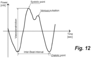
- the heart rate the inverse of the Inter-Beat-Interval shown in fig. 12
- a sample rate of 25 Hz will be sufficient.
- a sample rate may be increased to 50 or 100 Hz or even higher.
- the vasoconstriction is measured which is the power difference between the diatolic point and the systolic point.
- a high precision will be required, and a 24-bit sample size or even higher may be applied.
- sensors In general, it is preferred to design sensors according to their intended purpose with predefined sample rate and sample size.
- the sensor will anyway have to have a stimuli unit, if required, and a capturing unit.
- One embodiment according to the invention is based a sample size set to be 16 bits per sample. However, for certain purposes, larger sample sizes may be requested, e.g. 24-bit or 32-bit, which provides an almost infinite dynamic range, and only takes up twice as much storage as 16-bit samples.
- Fig. 6 illustrates how a plurality of devices are synchronized in one embodiment of a Time-division multiple access (TDMA) based wireless body area network according to the invention.
- At least one sensor device here slave devices 61.1 - 61.N, is wirelessly connected to a master device 60.
- Time-division multiple access is a channel access method allowing several devices to share the same frequency channel by dividing the signal into different time slots. The devices transmit in rapid succession, one after the other, each using its own time slot. This allows multiple devices to share the same radio frequency channel by using only a part of the channel capacity each.
- TDMA is based on a frame structure dividing a data stream into frames and further into time slots. A major advantage of TDMA is that the radio part of the devices only needs to listen and broadcast for its own time slot.
- the master device 60 is in one embodiment responsible for the time slot allocation to the slave devices 61.1 - 61.N in the wireless body area network.
- the master device 60 sends a synchronization message 62.1 as explained with reference to fig. 2 and 3 .
- the slave device 61.1 receives the synchronization message 62.1 and determines a time anchor point 63.1 as explained with reference to fig. 4 and 5 . Furthermore, the slave device 61.1 determines from the payload of the synchronization message 62.1 the duration, Tsense, of a sensing period 64, and the time, T1, from the time anchor point 63.1 to the start of the sensing period 64.
- the other slave devices 61.2 - 61.N do the same.
- master device 60 managing the timeslot allocation in advance calculates the time, T1 - TN, from the time anchor point 63.1 - 63.N to the start of the sensing period 64 individually of each of the slave devices 61.1 - 61.N and includes the individual time, T1 - TN, in the payload of the synchronization messages 62.1 - 62.N for a particular slave device 61.1 - 61.N.
- the slave devices 61.1 - 61.N are addressed individually by the master device 60, as the slave devices 61.1 - 61.N each have a unique ID used for addressing purposes.
- the slave device 61.1 - 61.N captures respective sensor signals representing physiologic parameters, packetizes the captured sensor signals into payload of one or more data packets 33 ( fig. 3 ) to be sent to the master device 60 in respective allocated uplink time slots. After a number of data packets 33, it may be appropriate to resynchronize the individual slave device 61.1 - 61.N to the master device 60 why the master device 60 sends a new synchronization message 32 even though the data capturing is ongoing.
- the new synchronization message 32 does not have to contain data capturing instructions as it just serves synchronization purposes.
- Fig. 7 illustrates how a plurality of devices are synchronized based on a broadcast message in one embodiment of a wireless body area network according to the invention.
- At least one sensor device here slave devices 61.1 - 61.N, is wirelessly connected to a master device 60.
- the master device 60 is in this embodiment responsible for the timing in the wireless body area network.
- the master device 60 sends a synchronization message 62 as broadcasted message to the group of slave devices 61.1 - 61.N.
- Each of the slave devices 61.1 - 61.N receives the synchronization message 62 and determines a time anchor point 63.1 - 61.N as explained with reference to fig. 4 and 5 .
- the slave devices 61.1 - 61N determines the duration, Tsense, of a sensing period 64, and the time, Tcommon, from the time anchor points 63.1 - 63.N to the start of the sensing period 64.
- the time, Tcommon is not critical as long as it is common for all the slave devices 61.1 - 61N.
- the time, Tcommon may be communicated by the master device 60 or set for all the slave devices 61.1 - 61N in advance.
- the slave devices 61.1 - 61.N captures respective sensor signals representing physiologic parameters, and packetizes the captured sensor signals into payload of one or more data packets 33 ( fig. 3 ).
- the slave devices 61.1 - 61.N may have a unique ID. The unique ID is not necessary for the broadcasted message 62 but is important when the slave devices 61.1 - 61.N send the packetized, captured sensor signals to the master device 60 in respective allocated uplink time slots or frequency channels. After a number of data packets 33, it may be appropriate to resynchronize the individual slave devices 61.1 - 61.N to the master device 60 why the master device 60 sends a new synchronization message 32 sent as a broadcasted message.
- Fig. 8 illustrates an embodiment with one sensor device to be synchronized with the master device according to one embodiment of the invention.
- At least one sensor device here slave device 61, is wirelessly connected to a master device 60.
- the master device 60 is in this embodiment responsible for the timing in the wireless body area network which in this embodiment consists of the slave device 61 having one or more sensors, e.g. a PPG sensor.
- the master device 60 may be a smartphone and include an accelerometer or other sensors. When processing synchronized sensor signals in the master device 60, the accelerometer signal is used for removing movement artefacts from the PPG signal.
- the master device 60 sends a synchronization message 62 to the slave device 61, and the slave device 61 determines upon reception a time anchor point 63 as explained with reference to fig. 4 and 5 .
- the slave devices 61 determines the duration, Tsense, of a sensing period 64, and the time, T, from the time anchor point 63 to the start of the sensing period 64.
- the master device uses the time, T, for activating its own sensor.
- the slave device 61 captures a sensor signal representing physiologic parameters and packetizes the captured sensor signals into payload of one or more data packets 33 ( fig. 3 ).
- the slave device 61 may have a unique ID. The unique ID is not necessarily necessary for the synchronization message 62 but may be valuable for signal encryption. Resynchronization of the sensor may be required from time to time.
- the sensor devices need to be synchronized, and when e.g. an EEG signal is monitored in a multi-sensor mesh, is has been observed that the origin and expansion of seizures can be detected when the sensors in the multi-sensor mesh are synchronized within 100 ⁇ sec. In one embodiment, the sensors are synchronized within 25 ⁇ sec. This is achievable when the data-rate of the Sync-word is 40 kbit per second or higher and the slave device 61.1 - 61.N avoids introducing individual delays in reading the Sync-word.
- Fig. 12 illustrates a pulse signal captured by a PPG sensor.
- Light produced by a green and a red LED is directed toward the skin and are absorbed by the blood. Portion of the light is reflected and captured by a photo detector.
- the light originating from the green LED contains most of the information on the pulse wave (i.e., the heartbeat) and it is typically characterized by a sequence of valleys used to estimate the heartbeat. It is worth noticing that oxygenated blood absorbs more light.
- the light originating from the red LED contains a reference light level which often is used to suppress motion artefacts.
- the PPG signal shown in fig. 12 is a periodic pulse signal having local minima called diastolic points used to compute an Inter-Beat-Interval.
- the periodic pulse signal has furthermore local maxima called systolic points that can be used in conjunction with the diastolic point to estimate the vasoconstriction of the object.
- a dicrotic notch may be observed between the systolic point and the venous pulsation, and this can be used to study different types of cardiac diseases.
- the difference of the PPG signal at the systolic point and the diastolic point is basically the difference in reflected light between the most and least oxygenated blood condition.
- this difference in light gives an information on the vasoconstriction of object.
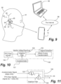
- FIG. 9 schematically illustrates a system for harvesting sensor data from at least one sensor device to a master device.
- the least one sensor device is in the illustrated embodiment a wearable EEG monitoring module 90.
- the user may wear one wearable EEG monitoring module 90 at each ear.
- the wearable EEG monitoring module 90 may be adapted for remote surveillance of an EEG signal.
- the person being monitored wears the wearable EEG monitoring module 90 comprising an implantable EEG sensor 93 and an associated processing unit 96.
- the implantable EEG sensor 93 and the processing unit 96 are adapted to be in wireless communication 95 through the skin of the person.
- the implantable EEG sensor 93 comprises electrodes 92.
- the Implantable EEG sensor 93 will have at least two electrodes 92, which may be arranged as separate electrodes along the same wire as illustrated. One wire comprising all electrodes associated with respective conductors may facilitate the implantation process.
- the Implantable EEG sensor 93 is adapted for implantation on the head 91. This implantation may be subcutaneous or intra cranial. The advantage is that a better contact between electrodes and tissue can be obtained. A subcutaneous EEG sensor can also be implanted relatively easy.
- the implantable EEG sensor 93 is provided with an electronic module 94 receiving one or more differential EEG signals from at least two electrodes 92.
- the processing unit 96 is preferably arranged at the ear of the person of whom the EEG signal is being monitored. Preferably, the processing unit 96 is arranged in a housing behind the ear. This also facilitates a position as close as possible to the implanted part, which is important for the wireless communication and power transfer through the skin.
- the wearable EEG monitoring module 90 communicates preferably with the personal communication device 10 - here shown as a smartphone - by means of the Bluetooth Low Energy protocol.
- the personal communication device 10 is Internet enabled which means that the personal communication device 10 may access the Internet 98 via a wireless Internet connection (e.g. WLAN), or a cellular data connection.
- the implantable EEG sensor 93 is via an inductive coupling 95 in communication with the processing unit 96.
- This inductive coupling 95 is applied to transfer power from the processing unit 96 to the implantable EEG sensor 93. Thereby, it is possible to operate the implantable EEG sensor 93 without a battery.
- the implantable EEG sensor 93 is connected to the processing unit 96 via wires.
- a server 99 hosts a centrally operated out-patient Electronic Medical Record (EMR) system or an electronic patient medical database being accessible over the Internet.
- EMR Electronic Medical Record
- Each patient record may involve remote surveillance of an EEG signal. This includes a unique identity for an associated EEG monitoring module 90.
- the user has two wearable EEG monitoring modules 90 acting as sensor devices according to the invention.
- the personal communication device 10 sends synchronization messages ( fig. 4 , step 40) to the two wearable EEG monitoring modules 90, start to capture synchronized sensor signals, e.g. differential EEG signals.
- the synchronized sensor signals are transmitted to the personal communication device 10, where the captured synchronized sensor signals are processed, or passed via the internet 98 to the server 99 for processing the captured synchronized sensor signals. It is important that captured sensor signals are still synchronized when processed.
- the personal communication device 10 and/or the server 99 are adapted to offer control elements, display alarm (together with an acoustic alarm), and present logged data.
- the patient medical record may be accessed in the patient record server 99 from where the unique identity for the EEG monitoring module in question may be retrieved.
- the personal communication device 10 operates as master device regarding sensor synchronization.
- the centrally operated out-patient Electronic Medical Record (EMR) system or an electronic patient medical database contains personal information such as name, address and additional contact data like phone number and e-mail address.
- Electroencephalography is an electrophysiological monitoring method to record electrical brain activity. When the electrodes placed along the scalp, the method is called noninvasive. The method illustrated with reference to fig. 9 uses invasive electrodes. EEG measures voltage fluctuations resulting from ionic current within the neurons of the brain.
- the EEG signal represents the brain's spontaneous electrical activity over time. Often multiple electrodes are arranged in a mesh arranged on the scalp.
- the EEG is typically a combination of rhythmic activity and transients.
- the rhythmic activity is divided into bands by frequency.
- the rhythmic activity for certain frequency ranges has been observed to have a certain distribution over the scalp or a certain biological significance.
- the major part of the cerebral signal observed in the scalp EEG is within the frequency range of 1-20 Hz, and the Waveforms are subdivided into bandwidths known as alpha, beta, theta, and delta.
- EEG may be used to e.g. diagnose epilepsy or monitoring hypoglycemia (low blood sugar), both causing abnormalities in EEG readings.
- EEG is a valuable tool for research and diagnosis as it is a mobile technique offering temporal resolution.
- the embodiment explained with reference to fig. 9 may be used for monitoring patients having epileptic seizures and for picking up EEG data for analyzing seizure expression, behavior (including origin prediction and monitoring whether the seizure becomes generalized), and brain morphology differences.
- a multi-site EEG sensor device mesh may be set upon allowing the patient to be monitored while his normal behavior is maintained.
- multiple synchronized channels will allow a better clean up the signals (signal processing) due to more information e.g. by using blind " source separation " or " independent component analysis " . Seizures may be clearer in one or more sensor due to its origin, and expansion can be observed. It will be possible to monitor both right and left temporal lobe simultaneously.
- a multi-site EEG mesh of synchronized sensor device offers significant potential for data mining, including deep learning.
- at least two EEG monitoring modules 90 are coupled via the master device 10 to a powerful computer 99 responsible for the deep learning calculations.
- the master device 10 extracts some physiological parameters, while the computer 99 extracts other physiological parameters for the deep learning calculations.
- the intended use of the signal specifies the required sample rate.
- the EEG signal has very high temporal resolution, on the order of milliseconds.
- EEG may be recorded at sampling rates between 250 and 2000 Hz which is like clinical and research settings.
- EEG data collection systems may record at sampling rates above 20 kHz.
- Raw data recorded at 2 kHz with a 24-bit sample size requires a data acquisition rate at 48 kbit/second. To minimize data buffering, this is the required data bandwidth between the EEG monitoring module 90 and the master device 10.
- Fig. 10 and 11 illustrates a method according to the invention for removing motion artefacts from PPG signals.
- a PPG Raw signal 100 received from a plurality of Slave Devices (e.g. the hearing aids 13 and 14 equipped with PPG sensors) and synchronized by the method as explained in fig. 4 .
- Motion artefacts is in general a problem as it significantly interferes with the desired physiological signals.
- the master device e.g. the personal communication device 10 which may be a smartphone.
- the raw signals are amplified, e.g. 10, 100 and 1000-fold for preventing signal saturation (clipping due to over amplification).
- the personal communication device 10 includes a triaxial accelerometer 101, and the output signal of a triaxial accelerometer 101 is applied to an adaptive filter 102 as a reference to remove motion artefacts.
- the motion artefact removal stage in a processor 105 is designed to remove motion artefacts using an adaptive filter 102.
- the raw signal 100 decomposed into a desired PPG signals, S, and inherent noise, N, is applied to an input of the adaptive filter 102, and the output signal of a triaxial accelerometer 101, here seen as noise, AS, is applied to the other input of the adaptive filter 102.
- the output signal, AS, of a triaxial accelerometer 101 will often represent steps of the user carrying the Slave Devices (e.g. the hearing aids 13 and 14) why AS often will be substantially correlated with the noise, N, but not with the signal, S, and applicable for removing the motion artefacts.
- the PPG signal, S is passed to a signal extraction unit in the processor 105, where a Hilbert-Huang transform (HHT) may be used for obtaining instantaneous frequency data by decomposing the PPG signal, S, into so-called Intrinsic Mode Functions along with a trend.
- HHT Hilbert-Huang transform
- the Hilbert-Huang transform (HHT) is designed to work well for data that is nonstationary and nonlinear. Then the instantaneous frequency data may be used for monitoring heart activity, pulse, blood pressure, etc., depending on where the sensors are positioned on the body of the monitored user.
- the operation of the adaptive filter 102 is illustrated in fig. 11 .
- the output signal, AS from the triaxial accelerometer 101, is used to remove the motion artefacts in a linear filter 105 having a transfer function, H, controlled by variable parameters.
- the linear filter 105 has an output Y determined by the transfer function H.
- the filter must be adaptive, using the output Z as a feedback signal for the linear filter 105 to control the transfer function, H.
Landscapes
- Health & Medical Sciences (AREA)
- Life Sciences & Earth Sciences (AREA)
- Engineering & Computer Science (AREA)
- General Health & Medical Sciences (AREA)
- Veterinary Medicine (AREA)
- Biophysics (AREA)
- Biomedical Technology (AREA)
- Heart & Thoracic Surgery (AREA)
- Medical Informatics (AREA)
- Molecular Biology (AREA)
- Surgery (AREA)
- Animal Behavior & Ethology (AREA)
- Physics & Mathematics (AREA)
- Public Health (AREA)
- Pathology (AREA)
- Cardiology (AREA)
- Signal Processing (AREA)
- Computer Networks & Wireless Communication (AREA)
- Physiology (AREA)
- Otolaryngology (AREA)
- Artificial Intelligence (AREA)
- Computer Vision & Pattern Recognition (AREA)
- Psychiatry (AREA)
- Vascular Medicine (AREA)
- Measuring And Recording Apparatus For Diagnosis (AREA)
- Measurement Of The Respiration, Hearing Ability, Form, And Blood Characteristics Of Living Organisms (AREA)
Claims (13)
- Système de surveillance comprenant un dispositif maître (10 ; 30 ; 61) conçu pour une communication sans fil avec deux dispositifs esclaves (13, 14 ; 31; 50; 62 ; 90) présentant chacun un capteur (15, 16 ; 93 ; 101) conçu pour acquérir un signal physiologique,- dans lequel le dispositif maître (10 ; 30 ; 61) est conçu pour- fournir des signaux de synchronisation aux deux dispositifs esclaves (13, 14 ; 31 ; 50; 62 ; 90), et- ordonner aux deux dispositifs esclaves (13, 14 ; 31; 50; 62 ; 90) d'acquérir le signal physiologique sur la base d'instructions de synchronisation,- dans lequel chacun des deux dispositifs esclaves (13, 14 ; 31; 50; 62 ; 90) est conçu pour- recevoir un message de synchronisation (32),- définir un point d'ancrage temporel (63) basé sur le message de synchronisation (32),- acquérir le signal physiologique au moyen du capteur (15, 16 ; 93 ; 101) selon des instructions de synchronisation reçues à un instant prédéterminé par rapport au point d'ancrage temporel (63), l'instant prédéterminé étant le même pour chacun des deux dispositifs esclaves (13, 14 ; 31 ; 50; 62 ; 90), et- envoyer sans fil le signal physiologique acquis au dispositif maître (10 ; 30 ; 61),dans lequel le dispositif maître (10 ; 30 ; 61) comprend un processeur (105) conçu pour traiter les signaux physiologiques acquis par les capteurs (15, 16 ; 93 ; 101) d'au moins deux dispositifs esclaves (13, 14 ; 30, 31; 60, 61) afin d'extraire une mesure pour un paramètre physiologique.
- Système de surveillance selon la revendication 1, dans lequel les deux dispositifs esclaves (13, 14 ; 31; 50; 62; 90) sont matérialisés par un ensemble de prothèses auditives (13, 14).
- Système de surveillance selon la revendication 1, dans lequel chacun des deux dispositifs esclaves (13, 14 ; 31 ; 50; 62; 90) est conçu pour coder le signal physiologique acquis en paquets de données numérisés et transmettre les paquets de données au dispositif maître (10 ; 30 ; 61).
- Système de surveillance selon la revendication 3, dans lequel chacun des deux dispositifs esclaves (13, 14 ; 31 ; 50; 62 ; 90) est conçu pour inclure des métadonnées de synchronisation dans les paquets de données numérisés transmis au dispositif maître (10 ; 30 ; 61).
- Système de surveillance selon la revendication 1, dans lequel le dispositif maître (10 ; 30 ; 61) est conçu pour- recevoir des paquets de données numérisés provenant des deux dispositifs esclaves (13, 14 ; 31 ; 50; 62 ; 90),- décoder les paquets de données numérisés reçus pour identifier les données de capteur et les métadonnées de synchronisation, et- traiter les données de capteur reçues provenant des deux dispositifs esclaves (13, 14 ; 31 ; 50; 62 ; 90) dans le processeur (105) pour extraire des caractéristiques physiologiques des données de capteur.
- Système de surveillance selon la revendication 1, dans lequel le processeur (105) est conçu pour traiter les signaux physiologiques acquis par des capteurs (15, 16 ; 93) présents dans les deux dispositifs esclaves (13, 14 ; 31; 50; 62 ; 90) et un autre capteur (101) présent dans le dispositif maître (10 ; 30 ; 61).
- Système de surveillance selon la revendication 1, dans lequel le processeur (105) est conçu pour traiter les signaux physiologiques acquis par un premier capteur (15, 16 ; 93) présent dans l'un des deux dispositifs esclaves (13, 14 ; 31 ; 50; 62 ; 90) et un second capteur (15, 16 ; 93) présent dans l'autre des deux dispositifs esclaves (13, 14 ; 31 ; 50 ; 62; 90).
- Système de surveillance selon la revendication 1, dans lequel le processeur (105) est conçu pour appliquer un filtre adaptatif (102) pour éliminer le bruit des signaux physiologiques acquis par les capteurs (15, 16 ; 93 ; 101) des deux dispositifs esclaves (13, 14; 31; 50; 62 ; 90).
- Système de surveillance selon la revendication 1, dans lequel l'un d'au moins deux dispositifs esclaves (13, 14 ; 30, 31 ; 60, 61) inclut un capteur photopléthysmographique, PPG, (15, 16) utilisant un oxymètre de pouls éclairant la peau et mesurant les changements d'absorption de lumière.
- Système de surveillance selon la revendication 2, dans lequel l'un d'au moins deux dispositifs esclaves (13, 14 ; 30, 31 ; 60, 61) inclut une électrode pour détecter un signal d'électroencéphalographie, EEG, provenant d'un conduit auditif d'un utilisateur de la prothèse auditive (13, 14).
- Système de surveillance selon la revendication 1, dans lequel le au moins un dispositif esclave (13, 14 ; 31; 50; 62 ; 90) est un module de surveillance EEG portable (90) conçu pour la surveillance à distance d'un signal EEG.
- Procédé de fonctionnement d'un système de surveillance comprenant un dispositif maître conçu pour la communication sans fil avec deux dispositifs esclaves présentant chacun un capteur conçu pour acquérir un signal physiologique, dans lequel le procédé comprend les étapes de,- fourniture de signaux de synchronisation aux deux appareils esclaves par l'appareil maître,- commande aux deux dispositifs esclaves d'acquérir le signal physiologique sur la base d'instructions de synchronisation pour la synchronisation par le dispositif maître,- réception d'un message de synchronisation par les deux appareils esclaves,- définition d'un point d'ancrage temporel basé sur le message de synchronisation des deux appareils esclaves,- acquisition du signal physiologique au moyen du capteur selon les instructions de synchronisation reçues par chacun des deux dispositifs esclaves à un instant prédéterminé par rapport au point d'ancrage temporel, l'instant prédéterminé étant le même pour chacun des deux dispositifs esclaves,- envoi sans fil du signal physiologique acquis depuis au moins deux dispositifs esclaves au dispositif maître, et- traitement dans le dispositif maître des signaux physiologiques acquis par les capteurs des deux dispositifs esclaves afin d'extraire une mesure pour un paramètre physiologique.
- Procédé selon la revendication 12, dans lequel chacun des au moins deux dispositifs esclaves est conçu pour inclure des métadonnées de synchronisation accompagnant le signal physiologique acquis envoyé au dispositif maître.
Applications Claiming Priority (1)
| Application Number | Priority Date | Filing Date | Title |
|---|---|---|---|
| US201862779574P | 2018-12-14 | 2018-12-14 |
Publications (3)
| Publication Number | Publication Date |
|---|---|
| EP3666178A1 EP3666178A1 (fr) | 2020-06-17 |
| EP3666178C0 EP3666178C0 (fr) | 2024-10-23 |
| EP3666178B1 true EP3666178B1 (fr) | 2024-10-23 |
Family
ID=68655333
Family Applications (1)
| Application Number | Title | Priority Date | Filing Date |
|---|---|---|---|
| EP19211147.4A Active EP3666178B1 (fr) | 2018-12-14 | 2019-11-25 | Système de surveillance comprenant un dispositif maître dans une communication sans fil avec au moins un dispositif esclave doté d'un capteur |
Country Status (2)
| Country | Link |
|---|---|
| US (1) | US11832949B2 (fr) |
| EP (1) | EP3666178B1 (fr) |
Families Citing this family (8)
| Publication number | Priority date | Publication date | Assignee | Title |
|---|---|---|---|---|
| US10993627B1 (en) * | 2017-01-24 | 2021-05-04 | James Eric Dotter | Device for determining blood pressure without a cuff |
| CA3140942A1 (fr) * | 2019-01-07 | 2020-07-16 | Cosinuss Gmbh | Procede de fourniture de donnees pour une interface |
| CN111107478B (zh) * | 2019-12-11 | 2021-04-09 | 江苏爱谛科技研究院有限公司 | 一种声音增强方法及声音增强系统 |
| US12526568B2 (en) | 2020-12-15 | 2026-01-13 | Starkey Laboratories, Inc. | Ear-worn electronic device incorporating skin contact and physiologic sensors |
| US12501734B2 (en) | 2020-12-16 | 2025-12-16 | Starkey Laboratories, Inc. | Electro-optical physiologic sensor |
| WO2022139818A1 (fr) * | 2020-12-22 | 2022-06-30 | Google Llc | Systèmes et procédé de ppg utilisant un capteur audio avec un dispositif pouvant être porté |
| JP2022181098A (ja) * | 2021-05-25 | 2022-12-07 | 富士フイルム株式会社 | 測定システム、測定方法及び測定プログラム |
| CN119449524A (zh) * | 2025-01-13 | 2025-02-14 | 慧创科仪(北京)科技有限公司 | 用于数台fnirs主机互联以形成更高检测通道数的fnirs数据采集方法 |
Citations (1)
| Publication number | Priority date | Publication date | Assignee | Title |
|---|---|---|---|---|
| US20120289792A1 (en) * | 2011-05-13 | 2012-11-15 | Fujitsu Limited | Creating a Personalized Stress Profile Using Renal Doppler Sonography |
Family Cites Families (18)
| Publication number | Priority date | Publication date | Assignee | Title |
|---|---|---|---|---|
| WO2002071305A2 (fr) * | 2001-03-08 | 2002-09-12 | Framtidartaekni Ehf. | Monitorage en ligne de la sante |
| CN101778405B (zh) | 2010-01-05 | 2013-01-02 | 武汉理工大学 | 结构健康监测的无线传感器网络同步采集方法及系统 |
| US20140257058A1 (en) | 2011-10-19 | 2014-09-11 | Scanadu Incorporated | Automated personal medical diagnostic system, method, and arrangement |
| US9471090B2 (en) | 2012-11-21 | 2016-10-18 | Starkey Laboratories, Inc. | Method and apparatus for synchronizing hearing instruments via wireless communication |
| WO2014168718A1 (fr) | 2013-03-15 | 2014-10-16 | University Of Florida Research Foundation, Inc. | Dispositifs et procédés de surveillance du flux sanguin directionnel et de la vitesse de l'onde de pouls par photopléthysmographie |
| WO2015072237A1 (fr) * | 2013-11-13 | 2015-05-21 | 株式会社Jvcケンウッド | Système d'analyse d'informations |
| US10278592B2 (en) | 2013-12-09 | 2019-05-07 | Samsung Electronics Co., Ltd. | Modular sensor platform |
| US9554724B2 (en) | 2013-12-11 | 2017-01-31 | Samsung Electronics Co., Ltd. | Self-aligning sensor array |
| WO2016065476A1 (fr) | 2014-10-30 | 2016-05-06 | 2352409 Ontario Inc. | Dispositif portable et procédé de surveillance non invasive continue de la pression artérielle et d'autres paramètres physiologiques, avec réduction des artéfacts de mouvement |
| DK3291730T3 (da) | 2015-05-04 | 2023-11-27 | T&W Eng A/S | Eeg-monitor med et hus individuelt tilpasset en person |
| DE102015015113A1 (de) | 2015-11-23 | 2017-05-24 | Biomedatronik UG (haftungsbeschränkt) | Verfahren und multisensor zum nichtinvasiven monitoring von physiologischen parameter und blutinhaltstoffe sowie frühdiagnose der pathologischen änderungen mittels fuzzy logik datafusion für decision making und consulting bei internet of things |
| GB2548420B (en) | 2016-06-10 | 2018-08-22 | Polar Electro Oy | Clock synchronization within wireless network |
| WO2018013569A1 (fr) | 2016-07-11 | 2018-01-18 | Mc10, Inc. | Système de mesure à capteurs multiples de la pression artérielle. |
| US20180092554A1 (en) | 2016-09-30 | 2018-04-05 | The Chinese University Of Hong Kong | Wearable and unobtrusive multi-sensor array and method for pulse wave velocity imaging |
| EP3351163B8 (fr) * | 2017-01-20 | 2020-04-15 | Byteflies NV | Procédé de synchronisation entre une pluralité de capteurs corporels sans fil et procédé de fonctionnement d'un réseau synchronisé de capteurs corporels sans fil |
| US10152830B2 (en) | 2017-02-06 | 2018-12-11 | Jawku L.L.C. A Delaware Co. | Camera-biometric motion sensor and method of synchronization |
| US11116415B2 (en) * | 2017-06-07 | 2021-09-14 | Bragi GmbH | Use of body-worn radar for biometric measurements, contextual awareness and identification |
| US10602987B2 (en) * | 2017-08-10 | 2020-03-31 | Arc Devices Limited | Multi-vital-sign smartphone system in an electronic medical records system |
-
2019
- 2019-11-25 EP EP19211147.4A patent/EP3666178B1/fr active Active
- 2019-12-12 US US16/712,230 patent/US11832949B2/en active Active
Patent Citations (1)
| Publication number | Priority date | Publication date | Assignee | Title |
|---|---|---|---|---|
| US20120289792A1 (en) * | 2011-05-13 | 2012-11-15 | Fujitsu Limited | Creating a Personalized Stress Profile Using Renal Doppler Sonography |
Also Published As
| Publication number | Publication date |
|---|---|
| US20200187809A1 (en) | 2020-06-18 |
| EP3666178A1 (fr) | 2020-06-17 |
| EP3666178C0 (fr) | 2024-10-23 |
| US11832949B2 (en) | 2023-12-05 |
Similar Documents
| Publication | Publication Date | Title |
|---|---|---|
| US11832949B2 (en) | Monitoring system comprising a master device in wireless communication with at least one slave device having a sensor | |
| Li et al. | Heartbeat driven medium access control for body sensor networks | |
| US20150282768A1 (en) | Physiological signal determination of bioimpedance signals | |
| US20150216475A1 (en) | Determining physiological state(s) of an organism based on data sensed with sensors in motion | |
| EP3267880B1 (fr) | Dispositif électronique portable pour traiter un signal acquis à partir d'un corps vivant, et procédé associé | |
| US20140327515A1 (en) | Combination speaker and light source responsive to state(s) of an organism based on sensor data | |
| US20140288447A1 (en) | Ear-related devices implementing sensors to acquire physiological characteristics | |
| CN114830689B (zh) | 电子设备中的方法、包括听力设备的系统和计算机可读存储介质 | |
| Andreoli et al. | SPINE-HRV: A BSN-based toolkit for heart rate variability analysis in the time-domain | |
| WO2022146883A1 (fr) | Systèmes, procédés et appareil pour générer des estimations biométriques à l'aide de données de photopléthysmographie en temps réel | |
| US20140128754A1 (en) | Multimodal physiological sensing for wearable devices or mobile devices | |
| US20220000374A1 (en) | Multi-modal body sensor monitoring and recording system based secured health-care infrastructure | |
| US20150264459A1 (en) | Combination speaker and light source responsive to state(s) of an environment based on sensor data | |
| WO2019077363A1 (fr) | Appareil et procédé d'électrocardiogramme | |
| Mendoza et al. | In-home wireless monitoring of physiological data for heart failure patients | |
| EP3986265B1 (fr) | Stadification du sommeil à l'aide d'une photopléthysmographie (ppg) intra-auriculaire | |
| Coccia et al. | Design and validation of an e-textile-based wearable system for remote health monitoring | |
| CN114027806A (zh) | 一种耳戴式生理信息采集装置 | |
| CN115191932A (zh) | 生理信号时间关联标记系统及多生理信号数据分析方法 | |
| CA3140942A1 (fr) | Procede de fourniture de donnees pour une interface | |
| Such | Motion tolerance in wearable sensors-The challenge of motion artifact | |
| US20190117105A1 (en) | Bi-hemispheric brain wave system and method of performing bi-hemispherical brain wave measurements | |
| KR101647944B1 (ko) | 혈당 및 심전도 통합 모니터링 장치 및 방법 | |
| CN118140274A (zh) | 用于检测心律异常的装置和系统 | |
| EP4563074A1 (fr) | Système modulaire et procédé de synchronisation de collecte de données de santé à capteurs multiples |
Legal Events
| Date | Code | Title | Description |
|---|---|---|---|
| PUAI | Public reference made under article 153(3) epc to a published international application that has entered the european phase |
Free format text: ORIGINAL CODE: 0009012 |
|
| STAA | Information on the status of an ep patent application or granted ep patent |
Free format text: STATUS: THE APPLICATION HAS BEEN PUBLISHED |
|
| AK | Designated contracting states |
Kind code of ref document: A1 Designated state(s): AL AT BE BG CH CY CZ DE DK EE ES FI FR GB GR HR HU IE IS IT LI LT LU LV MC MK MT NL NO PL PT RO RS SE SI SK SM TR |
|
| AX | Request for extension of the european patent |
Extension state: BA ME |
|
| STAA | Information on the status of an ep patent application or granted ep patent |
Free format text: STATUS: REQUEST FOR EXAMINATION WAS MADE |
|
| 17P | Request for examination filed |
Effective date: 20201217 |
|
| RBV | Designated contracting states (corrected) |
Designated state(s): AL AT BE BG CH CY CZ DE DK EE ES FI FR GB GR HR HU IE IS IT LI LT LU LV MC MK MT NL NO PL PT RO RS SE SI SK SM TR |
|
| STAA | Information on the status of an ep patent application or granted ep patent |
Free format text: STATUS: EXAMINATION IS IN PROGRESS |
|
| 17Q | First examination report despatched |
Effective date: 20220303 |
|
| GRAP | Despatch of communication of intention to grant a patent |
Free format text: ORIGINAL CODE: EPIDOSNIGR1 |
|
| STAA | Information on the status of an ep patent application or granted ep patent |
Free format text: STATUS: GRANT OF PATENT IS INTENDED |
|
| GRAS | Grant fee paid |
Free format text: ORIGINAL CODE: EPIDOSNIGR3 |
|
| INTG | Intention to grant announced |
Effective date: 20240822 |
|
| GRAA | (expected) grant |
Free format text: ORIGINAL CODE: 0009210 |
|
| STAA | Information on the status of an ep patent application or granted ep patent |
Free format text: STATUS: THE PATENT HAS BEEN GRANTED |
|
| RIN1 | Information on inventor provided before grant (corrected) |
Inventor name: KROMAN, MORTEN Inventor name: LARSEN, SOREN MOLLSKOV |
|
| AK | Designated contracting states |
Kind code of ref document: B1 Designated state(s): AL AT BE BG CH CY CZ DE DK EE ES FI FR GB GR HR HU IE IS IT LI LT LU LV MC MK MT NL NO PL PT RO RS SE SI SK SM TR |
|
| REG | Reference to a national code |
Ref country code: GB Ref legal event code: FG4D |
|
| REG | Reference to a national code |
Ref country code: CH Ref legal event code: EP |
|
| REG | Reference to a national code |
Ref country code: DE Ref legal event code: R096 Ref document number: 602019060733 Country of ref document: DE |
|
| REG | Reference to a national code |
Ref country code: IE Ref legal event code: FG4D |
|
| U01 | Request for unitary effect filed |
Effective date: 20241023 |
|
| U07 | Unitary effect registered |
Designated state(s): AT BE BG DE DK EE FI FR IT LT LU LV MT NL PT RO SE SI Effective date: 20241106 |
|
| U20 | Renewal fee for the european patent with unitary effect paid |
Year of fee payment: 6 Effective date: 20241107 |
|
| PG25 | Lapsed in a contracting state [announced via postgrant information from national office to epo] |
Ref country code: IS Free format text: LAPSE BECAUSE OF FAILURE TO SUBMIT A TRANSLATION OF THE DESCRIPTION OR TO PAY THE FEE WITHIN THE PRESCRIBED TIME-LIMIT Effective date: 20250223 Ref country code: HR Free format text: LAPSE BECAUSE OF FAILURE TO SUBMIT A TRANSLATION OF THE DESCRIPTION OR TO PAY THE FEE WITHIN THE PRESCRIBED TIME-LIMIT Effective date: 20241023 |
|
| PG25 | Lapsed in a contracting state [announced via postgrant information from national office to epo] |
Ref country code: ES Free format text: LAPSE BECAUSE OF FAILURE TO SUBMIT A TRANSLATION OF THE DESCRIPTION OR TO PAY THE FEE WITHIN THE PRESCRIBED TIME-LIMIT Effective date: 20241023 |
|
| PG25 | Lapsed in a contracting state [announced via postgrant information from national office to epo] |
Ref country code: NO Free format text: LAPSE BECAUSE OF FAILURE TO SUBMIT A TRANSLATION OF THE DESCRIPTION OR TO PAY THE FEE WITHIN THE PRESCRIBED TIME-LIMIT Effective date: 20250123 |
|
| PG25 | Lapsed in a contracting state [announced via postgrant information from national office to epo] |
Ref country code: GR Free format text: LAPSE BECAUSE OF FAILURE TO SUBMIT A TRANSLATION OF THE DESCRIPTION OR TO PAY THE FEE WITHIN THE PRESCRIBED TIME-LIMIT Effective date: 20250124 |
|
| PG25 | Lapsed in a contracting state [announced via postgrant information from national office to epo] |
Ref country code: PL Free format text: LAPSE BECAUSE OF FAILURE TO SUBMIT A TRANSLATION OF THE DESCRIPTION OR TO PAY THE FEE WITHIN THE PRESCRIBED TIME-LIMIT Effective date: 20241023 |
|
| PG25 | Lapsed in a contracting state [announced via postgrant information from national office to epo] |
Ref country code: RS Free format text: LAPSE BECAUSE OF FAILURE TO SUBMIT A TRANSLATION OF THE DESCRIPTION OR TO PAY THE FEE WITHIN THE PRESCRIBED TIME-LIMIT Effective date: 20250123 |
|
| PG25 | Lapsed in a contracting state [announced via postgrant information from national office to epo] |
Ref country code: SM Free format text: LAPSE BECAUSE OF FAILURE TO SUBMIT A TRANSLATION OF THE DESCRIPTION OR TO PAY THE FEE WITHIN THE PRESCRIBED TIME-LIMIT Effective date: 20241023 |
|
| PG25 | Lapsed in a contracting state [announced via postgrant information from national office to epo] |
Ref country code: MC Free format text: LAPSE BECAUSE OF FAILURE TO SUBMIT A TRANSLATION OF THE DESCRIPTION OR TO PAY THE FEE WITHIN THE PRESCRIBED TIME-LIMIT Effective date: 20241023 |
|
| PG25 | Lapsed in a contracting state [announced via postgrant information from national office to epo] |
Ref country code: SK Free format text: LAPSE BECAUSE OF FAILURE TO SUBMIT A TRANSLATION OF THE DESCRIPTION OR TO PAY THE FEE WITHIN THE PRESCRIBED TIME-LIMIT Effective date: 20241023 |
|
| PG25 | Lapsed in a contracting state [announced via postgrant information from national office to epo] |
Ref country code: CZ Free format text: LAPSE BECAUSE OF FAILURE TO SUBMIT A TRANSLATION OF THE DESCRIPTION OR TO PAY THE FEE WITHIN THE PRESCRIBED TIME-LIMIT Effective date: 20241023 |
|
| PLBE | No opposition filed within time limit |
Free format text: ORIGINAL CODE: 0009261 |
|
| STAA | Information on the status of an ep patent application or granted ep patent |
Free format text: STATUS: NO OPPOSITION FILED WITHIN TIME LIMIT |
|
| RAP4 | Party data changed (patent owner data changed or rights of a patent transferred) |
Owner name: WS AUDIOLOGY A/S |
|
| U1H | Name or address of the proprietor changed after the registration of the unitary effect |
Owner name: WS AUDIOLOGY A/S; DK |
|
| 26N | No opposition filed |
Effective date: 20250724 |
|
| PG25 | Lapsed in a contracting state [announced via postgrant information from national office to epo] |
Ref country code: IE Free format text: LAPSE BECAUSE OF NON-PAYMENT OF DUE FEES Effective date: 20241125 |
|
| U20 | Renewal fee for the european patent with unitary effect paid |
Year of fee payment: 7 Effective date: 20251022 |
|
| REG | Reference to a national code |
Ref country code: CH Ref legal event code: U11 Free format text: ST27 STATUS EVENT CODE: U-0-0-U10-U11 (AS PROVIDED BY THE NATIONAL OFFICE) Effective date: 20251201 |
|
| PGFP | Annual fee paid to national office [announced via postgrant information from national office to epo] |
Ref country code: GB Payment date: 20251023 Year of fee payment: 7 |
|
| PGFP | Annual fee paid to national office [announced via postgrant information from national office to epo] |
Ref country code: CH Payment date: 20251201 Year of fee payment: 7 |
|
| PG25 | Lapsed in a contracting state [announced via postgrant information from national office to epo] |
Ref country code: HU Free format text: LAPSE BECAUSE OF FAILURE TO SUBMIT A TRANSLATION OF THE DESCRIPTION OR TO PAY THE FEE WITHIN THE PRESCRIBED TIME-LIMIT; INVALID AB INITIO Effective date: 20191125 |
|
| PG25 | Lapsed in a contracting state [announced via postgrant information from national office to epo] |
Ref country code: CY Free format text: LAPSE BECAUSE OF FAILURE TO SUBMIT A TRANSLATION OF THE DESCRIPTION OR TO PAY THE FEE WITHIN THE PRESCRIBED TIME-LIMIT; INVALID AB INITIO Effective date: 20191125 |