EP3666181A1 - Affichage de type d'arythmie - Google Patents
Affichage de type d'arythmie Download PDFInfo
- Publication number
- EP3666181A1 EP3666181A1 EP19214705.6A EP19214705A EP3666181A1 EP 3666181 A1 EP3666181 A1 EP 3666181A1 EP 19214705 A EP19214705 A EP 19214705A EP 3666181 A1 EP3666181 A1 EP 3666181A1
- Authority
- EP
- European Patent Office
- Prior art keywords
- signals
- arrhythmia
- types
- different
- user interface
- Prior art date
- Legal status (The legal status is an assumption and is not a legal conclusion. Google has not performed a legal analysis and makes no representation as to the accuracy of the status listed.)
- Withdrawn
Links
Images


Classifications
-
- A—HUMAN NECESSITIES
- A61—MEDICAL OR VETERINARY SCIENCE; HYGIENE
- A61B—DIAGNOSIS; SURGERY; IDENTIFICATION
- A61B5/00—Measuring for diagnostic purposes; Identification of persons
- A61B5/24—Detecting, measuring or recording bioelectric or biomagnetic signals of the body or parts thereof
- A61B5/316—Modalities, i.e. specific diagnostic methods
- A61B5/318—Heart-related electrical modalities, e.g. electrocardiography [ECG]
- A61B5/346—Analysis of electrocardiograms
- A61B5/349—Detecting specific parameters of the electrocardiograph cycle
- A61B5/35—Detecting specific parameters of the electrocardiograph cycle by template matching
-
- A—HUMAN NECESSITIES
- A61—MEDICAL OR VETERINARY SCIENCE; HYGIENE
- A61B—DIAGNOSIS; SURGERY; IDENTIFICATION
- A61B18/00—Surgical instruments, devices or methods for transferring non-mechanical forms of energy to or from the body
- A61B18/04—Surgical instruments, devices or methods for transferring non-mechanical forms of energy to or from the body by heating
- A61B18/12—Surgical instruments, devices or methods for transferring non-mechanical forms of energy to or from the body by heating by passing a current through the tissue to be heated, e.g. high-frequency current
- A61B18/14—Probes or electrodes therefor
- A61B18/1402—Probes for open surgery
-
- A—HUMAN NECESSITIES
- A61—MEDICAL OR VETERINARY SCIENCE; HYGIENE
- A61B—DIAGNOSIS; SURGERY; IDENTIFICATION
- A61B5/00—Measuring for diagnostic purposes; Identification of persons
- A61B5/24—Detecting, measuring or recording bioelectric or biomagnetic signals of the body or parts thereof
- A61B5/316—Modalities, i.e. specific diagnostic methods
- A61B5/318—Heart-related electrical modalities, e.g. electrocardiography [ECG]
- A61B5/346—Analysis of electrocardiograms
- A61B5/349—Detecting specific parameters of the electrocardiograph cycle
- A61B5/364—Detecting abnormal ECG interval, e.g. extrasystoles, ectopic heartbeats
-
- A—HUMAN NECESSITIES
- A61—MEDICAL OR VETERINARY SCIENCE; HYGIENE
- A61B—DIAGNOSIS; SURGERY; IDENTIFICATION
- A61B34/00—Computer-aided surgery; Manipulators or robots specially adapted for use in surgery
- A61B34/20—Surgical navigation systems; Devices for tracking or guiding surgical instruments, e.g. for frameless stereotaxis
-
- A—HUMAN NECESSITIES
- A61—MEDICAL OR VETERINARY SCIENCE; HYGIENE
- A61B—DIAGNOSIS; SURGERY; IDENTIFICATION
- A61B5/00—Measuring for diagnostic purposes; Identification of persons
- A61B5/24—Detecting, measuring or recording bioelectric or biomagnetic signals of the body or parts thereof
- A61B5/25—Bioelectric electrodes therefor
- A61B5/279—Bioelectric electrodes therefor specially adapted for particular uses
- A61B5/28—Bioelectric electrodes therefor specially adapted for particular uses for electrocardiography [ECG]
- A61B5/283—Invasive
- A61B5/287—Holders for multiple electrodes, e.g. electrode catheters for electrophysiological study [EPS]
-
- A—HUMAN NECESSITIES
- A61—MEDICAL OR VETERINARY SCIENCE; HYGIENE
- A61B—DIAGNOSIS; SURGERY; IDENTIFICATION
- A61B5/00—Measuring for diagnostic purposes; Identification of persons
- A61B5/24—Detecting, measuring or recording bioelectric or biomagnetic signals of the body or parts thereof
- A61B5/316—Modalities, i.e. specific diagnostic methods
- A61B5/318—Heart-related electrical modalities, e.g. electrocardiography [ECG]
- A61B5/339—Displays specially adapted therefor
-
- A—HUMAN NECESSITIES
- A61—MEDICAL OR VETERINARY SCIENCE; HYGIENE
- A61B—DIAGNOSIS; SURGERY; IDENTIFICATION
- A61B5/00—Measuring for diagnostic purposes; Identification of persons
- A61B5/72—Signal processing specially adapted for physiological signals or for diagnostic purposes
- A61B5/7235—Details of waveform analysis
- A61B5/7246—Details of waveform analysis using correlation, e.g. template matching or determination of similarity
-
- A—HUMAN NECESSITIES
- A61—MEDICAL OR VETERINARY SCIENCE; HYGIENE
- A61B—DIAGNOSIS; SURGERY; IDENTIFICATION
- A61B90/00—Instruments, implements or accessories specially adapted for surgery or diagnosis and not covered by any of the groups A61B1/00 - A61B50/00, e.g. for luxation treatment or for protecting wound edges
- A61B90/06—Measuring instruments not otherwise provided for
-
- G—PHYSICS
- G06—COMPUTING OR CALCULATING; COUNTING
- G06T—IMAGE DATA PROCESSING OR GENERATION, IN GENERAL
- G06T11/00—Two-dimensional [2D] image generation
- G06T11/10—Texturing; Colouring; Generation of textures or colours
-
- G—PHYSICS
- G06—COMPUTING OR CALCULATING; COUNTING
- G06T—IMAGE DATA PROCESSING OR GENERATION, IN GENERAL
- G06T11/00—Two-dimensional [2D] image generation
- G06T11/20—Drawing from basic elements
- G06T11/26—Drawing of charts or graphs
-
- A—HUMAN NECESSITIES
- A61—MEDICAL OR VETERINARY SCIENCE; HYGIENE
- A61B—DIAGNOSIS; SURGERY; IDENTIFICATION
- A61B18/00—Surgical instruments, devices or methods for transferring non-mechanical forms of energy to or from the body
- A61B2018/00315—Surgical instruments, devices or methods for transferring non-mechanical forms of energy to or from the body for treatment of particular body parts
- A61B2018/00345—Vascular system
- A61B2018/00351—Heart
-
- A—HUMAN NECESSITIES
- A61—MEDICAL OR VETERINARY SCIENCE; HYGIENE
- A61B—DIAGNOSIS; SURGERY; IDENTIFICATION
- A61B18/00—Surgical instruments, devices or methods for transferring non-mechanical forms of energy to or from the body
- A61B2018/00571—Surgical instruments, devices or methods for transferring non-mechanical forms of energy to or from the body for achieving a particular surgical effect
- A61B2018/00595—Cauterization
-
- A—HUMAN NECESSITIES
- A61—MEDICAL OR VETERINARY SCIENCE; HYGIENE
- A61B—DIAGNOSIS; SURGERY; IDENTIFICATION
- A61B18/00—Surgical instruments, devices or methods for transferring non-mechanical forms of energy to or from the body
- A61B18/04—Surgical instruments, devices or methods for transferring non-mechanical forms of energy to or from the body by heating
- A61B18/12—Surgical instruments, devices or methods for transferring non-mechanical forms of energy to or from the body by heating by passing a current through the tissue to be heated, e.g. high-frequency current
- A61B18/14—Probes or electrodes therefor
- A61B2018/1467—Probes or electrodes therefor using more than two electrodes on a single probe
-
- A—HUMAN NECESSITIES
- A61—MEDICAL OR VETERINARY SCIENCE; HYGIENE
- A61B—DIAGNOSIS; SURGERY; IDENTIFICATION
- A61B34/00—Computer-aided surgery; Manipulators or robots specially adapted for use in surgery
- A61B34/20—Surgical navigation systems; Devices for tracking or guiding surgical instruments, e.g. for frameless stereotaxis
- A61B2034/2046—Tracking techniques
- A61B2034/2051—Electromagnetic tracking systems
-
- A—HUMAN NECESSITIES
- A61—MEDICAL OR VETERINARY SCIENCE; HYGIENE
- A61B—DIAGNOSIS; SURGERY; IDENTIFICATION
- A61B34/00—Computer-aided surgery; Manipulators or robots specially adapted for use in surgery
- A61B34/20—Surgical navigation systems; Devices for tracking or guiding surgical instruments, e.g. for frameless stereotaxis
- A61B2034/2046—Tracking techniques
- A61B2034/2065—Tracking using image or pattern recognition
-
- A—HUMAN NECESSITIES
- A61—MEDICAL OR VETERINARY SCIENCE; HYGIENE
- A61B—DIAGNOSIS; SURGERY; IDENTIFICATION
- A61B90/00—Instruments, implements or accessories specially adapted for surgery or diagnosis and not covered by any of the groups A61B1/00 - A61B50/00, e.g. for luxation treatment or for protecting wound edges
- A61B90/06—Measuring instruments not otherwise provided for
- A61B2090/064—Measuring instruments not otherwise provided for for measuring force, pressure or mechanical tension
- A61B2090/065—Measuring instruments not otherwise provided for for measuring force, pressure or mechanical tension for measuring contact or contact pressure
-
- G—PHYSICS
- G06—COMPUTING OR CALCULATING; COUNTING
- G06T—IMAGE DATA PROCESSING OR GENERATION, IN GENERAL
- G06T2200/00—Indexing scheme for image data processing or generation, in general
- G06T2200/24—Indexing scheme for image data processing or generation, in general involving graphical user interfaces [GUIs]
-
- G—PHYSICS
- G06—COMPUTING OR CALCULATING; COUNTING
- G06T—IMAGE DATA PROCESSING OR GENERATION, IN GENERAL
- G06T2210/00—Indexing scheme for image generation or computer graphics
- G06T2210/41—Medical
Definitions
- the present invention generally relates to signal analysis, and specifically to analysis of signals generated during a medical procedure.
- ECG electrocardiography
- Electrocardiography may be performed to detect cardiac problems such as arrhythmia of the heart as well as to monitor improvement in the condition of the heart after corrective procedures, for example, but not limited to, ablation therapy.
- a standard electrocardiograph may include connections to ten electrodes which are applied to the skin of the living subject including on the subject's limbs and on the chest. The electrical potential of the heart is then measured using the ten electrodes and is recorded over a time period. In this manner, the overall magnitude and direction of the heart's electrical depolarization is captured at each moment throughout the cardiac cycle. A graph of voltage versus time may be produced yielding an electrocardiogram.
- ECG data ECG data
- ancillary data locations of the catheter's distal tip and ablation energy being delivered to the heart tissue.
- US Patent No. 8,700,136 to Rubinstein describes a method for analyzing signals, including sensing a time-varying intracardiac potential signal and finding a fit of the time-varying intracardiac potential signal to a predefined oscillating waveform. The method further includes estimating an annotation time of the signal responsive to the fit.
- US Patent Publication No. 2011/0238127 of Conley, et al. describes systems, devices, structures, and methods to present a visual display based on data from an implantable medical device.
- the display includes a chart showing the frequency of a detected type of arrhythmia over a predetermined period of time.
- US Patent Publication No. 2010/0280400 of Ettori, et al. describes a cardiac rhythm management system used to detect episode beats associated with cardiac events in a subject's body. These events may be monitored and depolarization morphology information can be derived for candidate arrhythmic beats in an arrhythmia episode.
- An arrhythmic beat morphology template may be formed from selecting at least one of the candidate arrhythmic beats based upon user's labeling according to specific morphologies of one or more candidate episodes.
- ICD implantable cardioverter/defibrillator
- a tachyarrhythmia detection and classification system that classifies tachyarrhythmias based on a morphological analysis of arrhythmic waveforms and a template waveform.
- Correlation coefficients each computed between morphological features of an arrhythmic waveform and morphological features of the template waveform provide for the basis for classifying the tachyarrhythmia.
- a correlation analysis takes into account the uncertainty associated with the production of the template waveform by using a template band that includes confidence intervals.
- US Patent No. 4,336,810 to Anderson, et al. describes a method and apparatus for arrhythmia analysis of Holter-type ECG recordings including a tape playback unit having an analog signal output of successive ECG complexes or heart beats, a converter for generating data composites representing each complex, a computer for making and storing data templates in bins corresponding to operator classification of complexes as normal, supraventricular ectopic (SVE), ventricular ectopic (VE), or unknown, for comparing successive composites with stored templates and conditions to determine a match condition, and for signaling a corresponding event to an event counter and display.
- SVE supraventricular ectopic
- VE ventricular ectopic
- unknown for comparing successive composites with stored templates and conditions to determine a match condition
- the computer signals the tape playback to stop and to display an unmatched complex for operator classification and possible subsequent generation of a new template, after which scanning is resumed.
- US Patent Publication No. 2001/0056245 of Mlynash, et al. describes a noninvasive localization, characterization and classification apparatus and method for cardiac arrhythmias that enables discrete isolation of the intricate spatial and temporal detail in morphology of the atrial activity of interest from superimposed ventricular activity of a preceding heartbeat in a particular arrhythmia.
- An adaptive QRST subtraction template is used that is modulated for discrepancies in voltage and rate between the QRST template and arrhythmia signal.
- the QRST template modulation is accomplished by using one or more fiducial points and windows that are annotated in both the QRST template and the arrhythmia signal.
- a medical system including electrodes configured for application to a body of a subject and configured to output signals in response to electrical activity of a heart of the subject, a display, and a processor configured to store a set of templates corresponding to different types of arrhythmia of the heart, apply the templates to the signals so as to associate one or more different temporal sections of the signals with respective ones of the types of arrhythmia, and render to the display a user interface screen including at least a part of the signals and graphical identifiers identifying the different temporal sections of at least the part of the signals with the respective ones of the types of arrhythmia with which they are associated.
- the graphical identifiers are color-coded identifiers using a different color for different ones of the types of arrhythmia.
- the graphical identifiers are disposed in boxes below or above at least the part of the signals.
- the processor is configured to compute a relative proportion of the types of arrhythmia associated with the signals and render to the display the user interface screen including at least the part of the signals, the graphical identifiers, and statistics indicating the relative proportion of the types of arrhythmia associated with the signals.
- the statistics are disposed in a color-coded legend having a plurality of legend keys, each legend key textually describing one of the types of arrhythmia corresponding with one of the color-coded identifiers.
- the processor is configured to compute a relative proportion of the types of arrhythmia associated with the signals and render to the display the user interface screen including at least the part of the signals, the graphical identifiers, and statistics indicating the relative proportion of the types of arrhythmia associated with the signals.
- the processor is configured to render to the display another user interface screen including at least a part of another signal describing variations in a factor used in the analysis of the heart, and graphical identifiers identifying different sections of at least the part of the other signal with different ranges of the variations in the factor, the factor being selected from any one of the following: a force applied by a probe, a tissue proximity to the probe, a velocity of the probe, a cycle length, a position stability of the probe, and a local activation time (LAT) stability.
- LAT local activation time
- the processor is configured to generate the other user interface screen also to include statistics indicating a relative proportion of the different ranges of the variations in the factor.
- a medical method including receiving signals output by electrodes applied to a body of a subject in response to electrical activity of a heart of the subject, storing a set of templates corresponding to different types of arrhythmia of the heart, applying the templates to the signals so as to associate one or more different temporal sections of the signals with respective ones of the types of arrhythmia, and rendering to a display a user interface screen including at least a part of the signals and graphical identifiers identifying the different temporal sections of at least the part of the signals with the respective ones of the types of arrhythmia with which they are associated.
- the graphical identifiers are color-coded identifiers using a different color for different ones of the types of arrhythmia.
- the graphical identifiers are disposed in boxes below or above at least the part of the signals.
- the method includes computing a relative proportion of the types of arrhythmia associated with the signals, wherein the rendering includes rendering to the display the user interface screen including at least the part of the signals, the graphical identifiers, and statistics indicating the relative proportion of the types of arrhythmia associated with the signals.
- the statistics are disposed in a color-coded legend having a plurality of legend keys, each legend key textually describing one of the types of arrhythmia corresponding with one of the color-coded identifiers.
- the method includes computing a relative proportion of the types of arrhythmia associated with the signals, wherein the rendering includes rendering to the display the user interface screen including at least the part of the signals, the graphical identifiers, and statistics indicating the relative proportion of the types of arrhythmia associated with the signals.
- the method includes rendering to the display another user interface screen including at least a part of another signal describing variations in a factor used in analysis of the heart, and graphical identifiers identifying different sections of at least the part of the other signal with different ranges of the variations in the factor, the factor being selected from any one of the following a force applied by a probe, a tissue proximity to the probe, a velocity of the probe, a cycle length, a position stability of the probe, and a local activation time (LAT) stability.
- LAT local activation time
- the method includes generating the other user interface screen also to include statistics indicating a relative proportion of the different ranges of the variations in the factor.
- a software product including a non-transient computer-readable medium in which program instructions are stored, which instructions, when read by a central processing unit (CPU), cause the CPU to receive signals output by electrodes applied to a body of a subject in response to electrical activity of a heart of the subject, store a set of templates corresponding to different types of arrhythmia of the heart, apply the templates to the signals so as to associate one or more different temporal sections of the signals with respective ones of the types of arrhythmia, and render to a display a user interface screen including at least a part of the signals and graphical identifiers identifying the different temporal sections of at least the part of the signals with the respective ones of the types of arrhythmia with which they are associated.
- CPU central processing unit
- ECG signals body surface or intra-cardiac
- a physician may visually inspect graphs of the signals, and decide from the inspection what type and when the arrhythmia occurred. This sort of visual inspection is time-consuming, and is also open to error. Correct identification of arrhythmias is particularly critical during cardiac procedures such as ablation therapy, wherein ablations may be targeted according to the different arrhythmias present.
- the physician may set different filters to filter data according to what the physician deems to be the most important. For example, although the ECG data may be indicative of many different arrhythmias, the physician may set filters to detect one or more of the different types of arrhythmia based on pattern matching. As the heart rhythm may change while the procedure continues, for example, due to corrective measures being performed, the physician may change the filters during the procedure. Although employing the pattern matching reduces error, having to make an educated guess which filters are appropriate is still time-consuming and is also open to error.
- an apparatus renders a user interface screen to a display showing different temporal sections of ECG signals being automatically identified with respective types of arrhythmia.
- the different temporal sections may be identified with the respective types of arrhythmia using different colored and/or patterned identifiers and/or any suitable format including letters and/or digits.
- ECG signals include the different types of arrhythmia
- the physician can see at the same time all the arrhythmias included in the captured ECG signals shown in the user interface screen. This is particularly advantageous during a cardiac procedure where the flow of the procedure may be guided by the various arrhythmias that may need to be treated.
- the user interface screen may also include statistics indicating the relative proportion of the types of arrhythmia associated with the signals. This may easily enable the physician to prioritize the cardiac procedure according to the most prominent arrhythmias identified in the ECG data.
- the signals and its identifiers may be scrolled (left and right) to show different temporal sections of the signals.
- the data included in the user interface screen may be updated as the procedure progresses showing the relative proportion of the remaining types of arrhythmia in the ECG data thereby providing the physician with an indication of the current success of the procedure as well as the importance of any remaining arrhythmias.
- the apparatus may filter historical ECG data from any prior time period so that the user interface screen includes the ECG signals (or part thereof), how the ECG signals are identified with respective types of arrhythmia, and optionally the statistics indicating the relative proportion of the types of arrhythmia associated with the signals for the selected prior time period.
- the apparatus receives signals output by electrodes (body surface electrodes and/or catheter electrodes) applied to a body of a human patient in response to electrical activity of a heart of the human patient.
- a set of templates corresponding to different types of arrhythmia of the heart are stored by the apparatus.
- the apparatus applies the templates to the ECG signals so as to associate one or more different temporal sections of the signals with respective types of arrhythmia, for example, by comparing the templates to the signals using image comparison techniques or any suitable signal comparison technique.
- the apparatus computes a relative proportion (e.g., a percentage, fraction or ratio) of the types of arrhythmia associated with the signals.
- the relative proportion of an arrhythmia may be computed as the total time that the arrhythmia occurred out of the total time over which the ECG data under consideration was captured.
- the ECG data under consideration may be limited to the signals currently shown in the user interface screen or to some other configurable time window.
- the apparatus renders the user interface screen including at least a part of the ECG signals, a time scale detailing the timing of the various parts of the signals, graphical identifiers identifying the different temporal sections of at least the part of the signals with the respective types of arrhythmia with which they are associated, and statistics indicating the relative proportion of the types of arrhythmia associated with the signals.
- the graphical identifiers may be color-coded identifiers using a different color for different types of arrhythmia.
- the graphical identifiers may be disposed in boxes within an information strip below or above the displayed signals.
- the statistics may be disposed in a color-coded legend which has a legend key for each arrhythmia type.
- the relative proportion statistic of an arrhythmia type may be disposed in the legend key for that arrhythmia type or at any other suitable position in the user interface screen.
- the apparatus may render another user interface screen including at least a part of another signal describing variations in a factor used in analysis of the heart.
- This user interface screen also includes graphical identifiers identifying different sections of at least the part of the other signal with different ranges of the variations in the factor, and statistics indicating a relative proportion of the different ranges of the variations in the factor.
- the factor may be selected from any one of the following by way of example only: a force applied by a probe, a tissue proximity to the probe, a velocity of the probe, a cycle length, a position stability of the probe, and a local activation time (LAT) stability.
- LAT local activation time
- the signal may show how force applied by the probe varies over time.
- the graphical identifiers may identify different force ranges, e.g., 0-1 grams, 1-2 grams etc.
- the statistics may indicate the percentage of the force ranges, e.g., 20% at 0-1 grams, and 30% at 1-2 grams etc.
- Fig. 1 is a schematic illustration of an invasive medical procedure using an apparatus 12 according to an exemplary embodiment of the present invention.
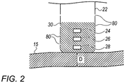
- Fig. 2 is a schematic illustration of a distal end 22 of a probe 20 used in the apparatus 12 according to an exemplary embodiment of the present invention.
- the procedure is performed by a physician 14, and in the description hereinbelow the procedure is assumed to comprise an ablation of a portion of tissue 15 of a myocardium 16 of the heart of a human patient 18.
- the physician 14 inserts the probe 20 into a sheath 21 that has been pre-positioned in a lumen of the patient 18 so that the probe 20 is inserted into a chamber of the heart.
- the sheath 21 is positioned so that the distal end 22 of the probe 20 enters the heart of the patient 18.
- the distal end 22 comprises a position sensor 24 that enables the location and orientation of the distal end 22 to be tracked, a force sensor 26 that measures the force applied by the distal end 22 when it contacts the myocardium 16, and one or more temperature sensors 28 that measure the temperature at respective locations of the distal end 22.
- the distal end 22 also comprises one or more electrodes 30 which are used to apply radiofrequency power to the myocardium 16 in the chamber so as to ablate the myocardium 16.
- the electrode(s) 30 may also be used to acquire electropotentials from the myocardium 16, as noted below.
- the apparatus 12 is controlled by a system processor 46, which is located in an operating console 48 of the apparatus.
- the operating console 48 comprises controls of at least one user input device 49 which are used by the physician 14 to communicate with the processor 46.
- the software for processor 46 may be downloaded to the processor 46 in electronic form, over a network, for example. Alternatively, or additionally, the software may be provided on non-transitory tangible media, such as optical, magnetic, or electronic storage media.
- the processor 46 may comprise real-time noise reduction circuitry 45, typically configured as a field programmable gate array (FPGA), followed by an analog-to-digital (A/D) signal conversion integrated circuit 47.
- the processor 46 can pass the signal from the A/D signal conversion integrated circuit 47 to another processor and/or can be programmed to perform at least one algorithm disclosed herein, the algorithm comprising steps described hereinbelow.
- the processor 46 uses the noise reduction circuitry 45 and the A/D signal conversion integrated circuit 47, as well as features of modules which are described in more detail below, in order to perform the algorithm.
- the algorithm run by the processor 46 communicates with a module bank 50, which has a number of modules used by the processor 46 to operate the apparatus 12.
- the module bank 50 comprises an electrocardiograph (ECG) module 56 coupled to receive signals from body surface electrodes 31 and/or electrodes 30, in order to provide the ECG signals to the processor 46.
- ECG electrocardiograph
- the body surface electrodes 31 and/or the electrode(s) 30 are configured for application to a body of a subject (e.g., the patient 18) and configured to output signals in response to electrical activity of a heart of the subject.
- the electrode(s) 30 is applied to the heart of the body via the probe 20.
- the module bank 50 also includes a tracking module 58 which receives and analyzes signals from the position sensor 24, and which uses the signal analysis to generate a location and an orientation of the distal end 22.
- the position sensor 24 comprises one or more coils which provide the sensor signals in response to magnetic fields traversing the coils.
- tracking module 58 in addition to receiving and analyzing signals from sensor 24, tracking module 58 also controls radiators 32, 34, and 36 which radiate the magnetic fields traversing the position sensor 24.
- the radiators 32, 34, 36 are positioned in proximity to the myocardium 16, and are configured to radiate alternating magnetic fields into a region in proximity to the myocardium 16.
- a plurality of wire connections 35 link the operating console 48 with body the surface electrodes 31 and other components (such as the radiators 32, 34, 36 and the sensor 24) to enable the tracking module 58 to measure location and orientation coordinates of the probe 20.
- the tracking module 58 is configured to compute a relative location and a relative orientation of the probe 20 with respect to the heart. Magnetic location and orientation tracking is described in U.S. Patent Nos. 7,756,576 and 7,536,218 , which are hereby incorporated by reference. The Carto® system produced by Biosense Webster, of 33 Technology Drive, Irvine, CA 92618 USA, uses such a magnetic tracking system.
- the tracking module 58 is not limited to using magnetic based location and orientation tracking. Any suitable location and orientation tracking can be used, such as impedance-based or image-based tracking.
- the apparatus 12 may receive image data from an external imaging modality, such as an MRI unit, CT unit or the like and includes image processors that can be incorporated in or invoked by the processor 46 for generating and displaying images.
- the image data may be registered with the tracking module 58 and an image 59 combining the received data and positions of the probe 20 may be displayed to the physician 14 on a display 61.
- the track of the distal end 22 of the probe 20 may be shown on a three-dimensional representation of the heart of patient 18 that is displayed on the display 61.
- a user interface screen 200 described in more detail with reference to Fig. 3 , may also be displayed on the display 61.
- the electrode(s) 30 and the body surface electrodes 31 may be used to measure tissue impedance at the ablation site as taught in U.S. Patent No. 7,536,218, issued to Govari et al. , which is herein incorporated by reference.
- the module bank 50 also comprises a force module 60, a power module 62, an irrigation module 64, and a temperature module 66. The functions of these modules are explained below.
- the modules in the module bank 50, and the processor 46, are herein termed processing circuitry 51.
- the force module 60 receives signals from the force sensor 26, and from the signals generates a magnitude of the contact force, herein assumed to be measured in grams, exerted by the distal end 22 on the tissue 15.
- the force sensor 26 is configured so that the signals it provides to the force module 60 enable the force module 60 to evaluate a direction of the force exerted by the distal end 22 on the tissue 15.
- the power module 62 comprises a radiofrequency (RF) signal generator 63 which generates the radiofrequency power to be applied by the electrode(s) 30 to ablate the tissue 15 of the myocardium 16.
- the processor 46 and the power module 62 are able to adjust a power level, herein assumed to be measured in Watts, delivered by the electrode(s) 30, as well as a length of time, measured in seconds, during which the power is delivered.
- the irrigation module 64 controls a rate of flow, herein assumed to be measured in mL/min, of irrigation fluid, typically normal saline solution, supplied to the distal end 22 by a pump 65 disposed in the operating console 48.
- the probe 20 includes an irrigation channel through which to irrigate the myocardium 16.
- the irrigation fluid is expelled from irrigation holes 80 in the distal end 22.
- the pump 65 is configured to selectively pump the irrigation fluid into the irrigation channel at an idle rate and at one or more one non-idle rates (higher than the idle rate) according to a status of the ablation procedure.
- the temperature module 66 receives a temperature signal provided by the temperature sensor 28 (or by each temperature sensor 28).
- the temperature signal is indicative of a temperature of the myocardium at a plurality of different times.
- the temperature module 66 determines the temperatures registered by each of the sensors 28. Typically, in the case of multiple sensors 28 the temperature module 66 determines a mean temperature of the distal end 22. Additionally, in the case of multiple sensors, the temperature module 66 may produce a map of the temperature distribution of the distal end 22.
- the electrocardiograph (ECG) module 56 may be implemented independently of the apparatus 12 without the probe 20 and the various ablation functionality described above. In these exemplary embodiments, the electrocardiograph (ECG) module 56 may be implemented in a stand-alone ECG system with a display screen for showing the user interface screen 200 or as part of any other suitable system.
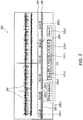
- Fig. 3 is a view of the exemplary user interface screen 200 rendered by the apparatus 12 of Fig. 1 .
- the body surface electrodes 31 and/or the electrode(s) 30 applied to the body of the human patient 18 output signals 202 in response to electrical activity of the heart of the human patient 18.
- the signals 202 may be processed by the processor 46 to remove noise. Other processing of the signals 202 is described in more detail with reference to Fig. 4 including identifying different arrhythmia types in the signals 202.
- the processor 46 is configured to render to the display 61 the user interface screen 200, and example of which is shown in Fig. 3 .
- the user interface screen 200 may include any one or more of the following:
- the signals 202 may be scrolled (left and right) in the user interface screen 200 so that different temporal sections of the signals 202 may be shown in the user interface screen 200 at different times. As the signals 202 are scrolled the time scale 204 also scrolls corresponding to the timing associated with the signals 202 being shown. The graphical identifiers are also amended to reflect the types of arrhythmia included in the signals 202 now shown in the user interface screen 200.
- the graphical identifiers 208 are color-coded identifiers using a different color for the different types of arrhythmia.
- the graphical identifiers 208 are disposed in boxes within an information strip 206 below or above at least the part of the signals 202.
- the color-coded legend 210 includes a plurality of legend keys 212 where each key 212 textually describes its corresponding arrhythmia type and is colored according to the color indicating that arrhythmia type in the corresponding color-coded identifier.
- the statistics for each arrhythmia may be disposed in the legend key 212 for that arrhythmia type. Alternatively, the statistics may be disposed at any suitable position on the user interface screen 200.
- the statistics may be formatted as a percentage, fraction or ratio, by way of example only.
- the relative proportion of an arrhythmia may be computed as the total time that the arrhythmia occurred out of the total time over which the ECG data under consideration was captured.
- the total time used in the computation of the relative proportion may be the total time of the ECG signal currently shown on the user interface screen 200 or the total time of the ECG signal captured for a time period larger than the time period currently shown on the user interface screen 200 such as the time period for which ECG data is available or for a different time period configured by the physician 14.
- PVC-A arrhythmia is identified in the information strip 206 using the graphical identifier 208-1, in the color-coded legend 210 using the legend key 212-1, and its relative proportion of 6% in the legend key 212-1.
- Sinus arrhythmia is identified in the information strip 206 using the graphical identifier 208-2, in the color-coded legend 210 using the legend key 212-2, and its relative proportion of 88% in the legend key 212-2.
- PVC-B arrhythmia is identified in the information strip 206 using the graphical identifier 208-4, in the color-coded legend 210 using the legend key 212-4, and its relative proportion of 2% in the legend key 212-4.
- Other arrhythmia types are grouped and are identified in the information strip 206 using the graphical identifier 208-3, in the color-coded legend 210 using the legend key 212-3, and its relative proportion of 4% in the legend key 212-3.
- the color-coding of the graphical identifiers 208 may be replaced with, or supplemented by, different patterned identifiers and/or any suitable format for distinguishing the different arrhythmias including letters (e.g., PVC A, PVC B) and/or digits.
- the color-coded legend 210 may be suitably amended to provide an appropriate legend for the graphical identifiers 208.
- the lines of the signals 202 may be colored or otherwise formatted to identify the different temporal sections of the signals 202 with the arrhythmia types.
- FIG. 4 is a view of a flowchart 300 including exemplary steps in a method of operation of the apparatus 12 of Fig. 1 .
- steps represented by blocks 302-310 may be performed in any suitable order. Additionally, some of the steps may be performed simultaneously.
- the processor 46 is configured to receive (block 302) signals 202 ( Fig. 3 ) output by the body surface electrodes 31 and/or the electrode(s) 30 applied to the body of the human patient 18 in response to electrical activity of the heart of the human patient 18.
- the processor 46 is configured to store (block 304) a set of templates corresponding to different types of arrhythmia of the heart.
- the processor 46 is configured to apply (block 306) the templates to the signals 202 so as to associate one or more different temporal sections of the signals 202 with respective ones of the types of arrhythmia. This step may include comparing the templates to the signals 202, for example, using image comparison techniques or any suitable signal comparison technique.
- the processor 46 may be configured to compute (block 308) a relative proportion of the types of arrhythmia associated with the signals 202 as a percentage, fraction or ratio, by way of example only.
- the relative proportion of an arrhythmia type may be computed as the total time that the arrhythmia type occurred out of the total time over which the ECG data under consideration was captured.
- the total time used in the computation of the relative proportion may be the total time of the ECG signal 202 currently shown on the user interface screen 200 or the total time of the ECG signal captured for a time period larger than the time period currently shown on the user interface screen 200 such as the time period for which ECG data is available or for a different time period configured by the physician 14.
- the processor 46 is configured to render (block 310) the user interface screen 200 to the display 61.
- the user interface screen 200 may include any one or more of the following:
- the processor 46 is configured to provide data of one or more other factors that may be selected from any one of the following: a force applied by the probe 20, a tissue proximity to the probe 20, a velocity of the probe 20, a cycle length, a position stability of the probe 20, and a local activation time (LAT) stability.
- the processor 46 is configured to compute statistics for a selected factor as described below in more detail.
- the processor 46 is configured to render to the display 61 another user interface screen substantially the same as the user interface screen 200 but with modifications relevant to the selected factor. This other user interface screen may include:
- the signal is a representation of force applied by the probe 20 versus time, and the different ranges of the factor may be 0-1 grams, 1-2 grams etc.
- the statistics may be 30% for 0-1 grams and 20% for 1-2 grams etc.
- the signal is a representation of tissue proximity versus time, and the different ranges of the factor may be 0-1 mm, 1-2 mm etc.
- the statistics may be 10% for 0-1 mm and 20% for 1-2 mm etc.
- the signal is a representation of velocity versus time
- the different ranges of the factor may be 0-0.01 meters per second (m/s), 0.01-0.02 m/s etc.
- the statistics may be 10% for 0-0.01 m/s and 15% for 0.01-0.02 m/s etc.
- the signal is a representation of cycle length versus time, and the different ranges of the factor may be 0-50 milliseconds (ms), 50-100 ms etc.
- the statistics may be 50% for 0-50 ms and 10% for 50-100 ms etc.
- the signal is a representation of position stability versus time, and the different ranges of the factor may be 0-1 mm, 1-2 mm etc.
- the statistics may be 10% for 0-1 mm and 20% for 1-2 mm etc.
- the signal is a representation of LAT stability versus time, and the different ranges of the factor may be 0-10 ms, 10-20 ms etc.
- the statistics may be 23% for 0-10 ms and 45% for 1-2 ms etc.
- the graphical identifiers are color-coded identifiers using a different color for the different ranges of the selected factor.
- the graphical identifiers may be disposed in boxes within an information strip below or above at least the part of the signal(s).
- the color-coded legend may include legend keys where each key textually describes its corresponding factor range and is colored according to the color indicating that factor range in the corresponding color-coded identifier.
- the statistics for each factor range may be disposed in the legend key for that factor range or in any other suitable position in the other user interface screen. The statistics may be formatted as a percentage, fraction or ratio, by way of example only.
- the relative proportion of a factor range may be computed as the total time that the factor range occurred out of the total time over which the factor data under consideration was captured.
- the total time used in the computation of the relative proportion may be the total time of the factor signal currently shown on the other user interface screen or the total time for a time period larger than the time period currently shown on the other user interface screen such as the time period for which factor signal data is available or for a different time period configured by the physician 14.
- the color-coding of the graphical identifiers may be replaced with, or supplemented by, different patterned identifiers and/or any suitable format for distinguishing the different factor ranges including letters (e.g., Force range A, Force range B) and/or digits.
- the color-coded legend may be suitably amended to provide an appropriate legend for the graphical identifiers.
- the lines of the signal(s) may be colored or otherwise formatted to identify the different temporal sections of the signal(s) with the different factor ranges.
Landscapes
- Health & Medical Sciences (AREA)
- Life Sciences & Earth Sciences (AREA)
- Engineering & Computer Science (AREA)
- Surgery (AREA)
- Cardiology (AREA)
- Public Health (AREA)
- General Health & Medical Sciences (AREA)
- Physics & Mathematics (AREA)
- Biomedical Technology (AREA)
- Heart & Thoracic Surgery (AREA)
- Medical Informatics (AREA)
- Molecular Biology (AREA)
- Veterinary Medicine (AREA)
- Animal Behavior & Ethology (AREA)
- Pathology (AREA)
- Biophysics (AREA)
- Nuclear Medicine, Radiotherapy & Molecular Imaging (AREA)
- Physiology (AREA)
- General Physics & Mathematics (AREA)
- Theoretical Computer Science (AREA)
- Artificial Intelligence (AREA)
- Signal Processing (AREA)
- Psychiatry (AREA)
- Computer Vision & Pattern Recognition (AREA)
- Plasma & Fusion (AREA)
- Oral & Maxillofacial Surgery (AREA)
- Robotics (AREA)
- Otolaryngology (AREA)
- Measurement And Recording Of Electrical Phenomena And Electrical Characteristics Of The Living Body (AREA)
Applications Claiming Priority (2)
| Application Number | Priority Date | Filing Date | Title |
|---|---|---|---|
| US201862778022P | 2018-12-11 | 2018-12-11 | |
| US16/553,745 US20200178831A1 (en) | 2018-12-11 | 2019-08-28 | Display of arrhythmia type |
Publications (1)
| Publication Number | Publication Date |
|---|---|
| EP3666181A1 true EP3666181A1 (fr) | 2020-06-17 |
Family
ID=68847979
Family Applications (1)
| Application Number | Title | Priority Date | Filing Date |
|---|---|---|---|
| EP19214705.6A Withdrawn EP3666181A1 (fr) | 2018-12-11 | 2019-12-10 | Affichage de type d'arythmie |
Country Status (5)
| Country | Link |
|---|---|
| US (1) | US20200178831A1 (fr) |
| EP (1) | EP3666181A1 (fr) |
| JP (1) | JP2020093096A (fr) |
| CN (1) | CN111297471A (fr) |
| IL (1) | IL270411A (fr) |
Cited By (2)
| Publication number | Priority date | Publication date | Assignee | Title |
|---|---|---|---|---|
| US12310737B2 (en) | 2020-09-30 | 2025-05-27 | Boston Scientific Scimed, Inc. | Interactive 2D scatter plot of EGM characteristic metrics |
| US12471828B2 (en) | 2020-09-30 | 2025-11-18 | Boston Scientific Scimed, Inc. | Electrophysiology system and method for determining local cycle length and local duty cycle |
Families Citing this family (4)
| Publication number | Priority date | Publication date | Assignee | Title |
|---|---|---|---|---|
| US11730414B2 (en) * | 2020-01-21 | 2023-08-22 | Biosense Webster (Israel) Ltd. | Automatic pattern acquisition |
| US20220068483A1 (en) * | 2020-09-01 | 2022-03-03 | Biosense Webster (Israel) Ltd. | Arrhythmia classification for cardiac mapping |
| US12364426B2 (en) * | 2021-08-12 | 2025-07-22 | Biosense Webster (Israel) Ltd. | Electro-anatomical mapping and annotation presented in electrophysiological procedures |
| US20250185973A1 (en) * | 2023-12-12 | 2025-06-12 | Biosense Webster (Israel) Ltd. | Gui to visually connect features identified in electroanatomical (ea) map to ecg signals |
Citations (13)
| Publication number | Priority date | Publication date | Assignee | Title |
|---|---|---|---|---|
| US4336810A (en) | 1980-09-30 | 1982-06-29 | Del Mar Avionics | Method and apparatus for arrhythmia analysis of ECG recordings |
| US20010056245A1 (en) | 2000-03-15 | 2001-12-27 | Mlynash Michael D. | QRST subtraction using an adaptive template for analysis of TU wave obscured atrial activity |
| US20080188765A1 (en) * | 2007-01-11 | 2008-08-07 | Silvia Stolarski | Automated pace-mapping for identification of cardiac arrhythmic conductive pathways and foci |
| US20090005826A1 (en) | 2005-01-20 | 2009-01-01 | Cardiac Pacemakers, Inc. | Method and apparatus for cardiac arrhythmia classification using template band-based morphology analysis |
| US7536218B2 (en) | 2005-07-15 | 2009-05-19 | Biosense Webster, Inc. | Hybrid magnetic-based and impedance-based position sensing |
| US7756576B2 (en) | 2005-08-26 | 2010-07-13 | Biosense Webster, Inc. | Position sensing and detection of skin impedance |
| US20100204552A1 (en) * | 2007-07-30 | 2010-08-12 | Omron Healthcare Co., Ltd. | Apparatus for monitoring biological information |
| US20100268103A1 (en) * | 2009-04-16 | 2010-10-21 | Cardionet, Inc. | Cardiac Arrhythmia Report |
| US20100280400A1 (en) | 2006-12-08 | 2010-11-04 | Benjamin Ettori | Rate aberrant beat selection and template formation |
| US20110066202A1 (en) * | 2009-09-17 | 2011-03-17 | Pacesetter, Inc. | Electrode and lead stability indexes and stability maps based on localization system data |
| US20110238127A1 (en) | 1999-08-20 | 2011-09-29 | Conley Vickie L | Arrhythmia display |
| US20130296845A1 (en) * | 2012-05-07 | 2013-11-07 | Meir Bar-tal | Automatic ablation tracking |
| US8700136B2 (en) | 2011-11-11 | 2014-04-15 | Biosense Webster (Israel), Ltd. | Accurate time annotation of intracardiac ECG signals |
-
2019
- 2019-08-28 US US16/553,745 patent/US20200178831A1/en not_active Abandoned
- 2019-11-04 IL IL270411A patent/IL270411A/en unknown
- 2019-12-10 JP JP2019222725A patent/JP2020093096A/ja active Pending
- 2019-12-10 EP EP19214705.6A patent/EP3666181A1/fr not_active Withdrawn
- 2019-12-11 CN CN201911265769.5A patent/CN111297471A/zh active Pending
Patent Citations (13)
| Publication number | Priority date | Publication date | Assignee | Title |
|---|---|---|---|---|
| US4336810A (en) | 1980-09-30 | 1982-06-29 | Del Mar Avionics | Method and apparatus for arrhythmia analysis of ECG recordings |
| US20110238127A1 (en) | 1999-08-20 | 2011-09-29 | Conley Vickie L | Arrhythmia display |
| US20010056245A1 (en) | 2000-03-15 | 2001-12-27 | Mlynash Michael D. | QRST subtraction using an adaptive template for analysis of TU wave obscured atrial activity |
| US20090005826A1 (en) | 2005-01-20 | 2009-01-01 | Cardiac Pacemakers, Inc. | Method and apparatus for cardiac arrhythmia classification using template band-based morphology analysis |
| US7536218B2 (en) | 2005-07-15 | 2009-05-19 | Biosense Webster, Inc. | Hybrid magnetic-based and impedance-based position sensing |
| US7756576B2 (en) | 2005-08-26 | 2010-07-13 | Biosense Webster, Inc. | Position sensing and detection of skin impedance |
| US20100280400A1 (en) | 2006-12-08 | 2010-11-04 | Benjamin Ettori | Rate aberrant beat selection and template formation |
| US20080188765A1 (en) * | 2007-01-11 | 2008-08-07 | Silvia Stolarski | Automated pace-mapping for identification of cardiac arrhythmic conductive pathways and foci |
| US20100204552A1 (en) * | 2007-07-30 | 2010-08-12 | Omron Healthcare Co., Ltd. | Apparatus for monitoring biological information |
| US20100268103A1 (en) * | 2009-04-16 | 2010-10-21 | Cardionet, Inc. | Cardiac Arrhythmia Report |
| US20110066202A1 (en) * | 2009-09-17 | 2011-03-17 | Pacesetter, Inc. | Electrode and lead stability indexes and stability maps based on localization system data |
| US8700136B2 (en) | 2011-11-11 | 2014-04-15 | Biosense Webster (Israel), Ltd. | Accurate time annotation of intracardiac ECG signals |
| US20130296845A1 (en) * | 2012-05-07 | 2013-11-07 | Meir Bar-tal | Automatic ablation tracking |
Cited By (2)
| Publication number | Priority date | Publication date | Assignee | Title |
|---|---|---|---|---|
| US12310737B2 (en) | 2020-09-30 | 2025-05-27 | Boston Scientific Scimed, Inc. | Interactive 2D scatter plot of EGM characteristic metrics |
| US12471828B2 (en) | 2020-09-30 | 2025-11-18 | Boston Scientific Scimed, Inc. | Electrophysiology system and method for determining local cycle length and local duty cycle |
Also Published As
| Publication number | Publication date |
|---|---|
| CN111297471A (zh) | 2020-06-19 |
| US20200178831A1 (en) | 2020-06-11 |
| IL270411A (en) | 2020-06-30 |
| JP2020093096A (ja) | 2020-06-18 |
Similar Documents
| Publication | Publication Date | Title |
|---|---|---|
| JP7789485B2 (ja) | 自動パターン取得 | |
| US20230334077A1 (en) | Automatic pattern acquisition | |
| EP3666181A1 (fr) | Affichage de type d'arythmie | |
| US10076260B2 (en) | Integrated analysis of electrophysiological data | |
| JP6200590B2 (ja) | 電気生理学的マップを生成するためのシステムおよび方法 | |
| CN106102568B (zh) | 与治疗部位相关的信号分析 | |
| JP2018140171A (ja) | 電極信号に従った電極画像の強調表示 | |
| US20140058246A1 (en) | System and methods for real-time cardiac mapping | |
| EP3827749B1 (fr) | Cartographie des temps d'activation locaux pour les cycles cardiaques des sinus et des non-sinus | |
| US20230226361A1 (en) | Cardiac mapping to evaluate impact of interventions | |
| US20230190104A1 (en) | Automated mapping and/or signal processing responsive to cardiac signal features | |
| US10149626B1 (en) | Methods and systems for mapping and ablation of cardiac arrhythmias comprising atrial flutter | |
| EP3669767B1 (fr) | Visualisation de différents rythmes cardiaques utilisant différents affichages de motifs de temporisation | |
| US20250241579A1 (en) | Ecg activation pattern clustering template analysis | |
| US20250009277A1 (en) | Cardiac diagnostic system | |
| WO2023135475A1 (fr) | Cartographie cardiaque pour évaluer un impact d'interventions | |
| EP4452068A1 (fr) | Cartographie automatisée et/ou traitement de signal en réponse à des caractéristiques de signal cardiaque | |
| CN118414122A (zh) | 响应于心脏信号特征的自动标测和/或信号处理 | |
| IL293942A (en) | Improving mapping resolution of electrophysiological (ep) wave propagating on the surface of patient heart |
Legal Events
| Date | Code | Title | Description |
|---|---|---|---|
| PUAI | Public reference made under article 153(3) epc to a published international application that has entered the european phase |
Free format text: ORIGINAL CODE: 0009012 |
|
| STAA | Information on the status of an ep patent application or granted ep patent |
Free format text: STATUS: THE APPLICATION HAS BEEN PUBLISHED |
|
| AK | Designated contracting states |
Kind code of ref document: A1 Designated state(s): AL AT BE BG CH CY CZ DE DK EE ES FI FR GB GR HR HU IE IS IT LI LT LU LV MC MK MT NL NO PL PT RO RS SE SI SK SM TR |
|
| AX | Request for extension of the european patent |
Extension state: BA ME |
|
| STAA | Information on the status of an ep patent application or granted ep patent |
Free format text: STATUS: REQUEST FOR EXAMINATION WAS MADE |
|
| 17P | Request for examination filed |
Effective date: 20201215 |
|
| RBV | Designated contracting states (corrected) |
Designated state(s): AL AT BE BG CH CY CZ DE DK EE ES FI FR GB GR HR HU IE IS IT LI LT LU LV MC MK MT NL NO PL PT RO RS SE SI SK SM TR |
|
| STAA | Information on the status of an ep patent application or granted ep patent |
Free format text: STATUS: EXAMINATION IS IN PROGRESS |
|
| 17Q | First examination report despatched |
Effective date: 20211026 |
|
| STAA | Information on the status of an ep patent application or granted ep patent |
Free format text: STATUS: THE APPLICATION HAS BEEN WITHDRAWN |
|
| 18W | Application withdrawn |
Effective date: 20211129 |