EP3666183B1 - Bioimpedanzmessverfahren und vorrichtung mit elektrischer stimulation - Google Patents
Bioimpedanzmessverfahren und vorrichtung mit elektrischer stimulation Download PDFInfo
- Publication number
- EP3666183B1 EP3666183B1 EP19214087.9A EP19214087A EP3666183B1 EP 3666183 B1 EP3666183 B1 EP 3666183B1 EP 19214087 A EP19214087 A EP 19214087A EP 3666183 B1 EP3666183 B1 EP 3666183B1
- Authority
- EP
- European Patent Office
- Prior art keywords
- current
- frequency
- low
- electrodes
- frequency current
- Prior art date
- Legal status (The legal status is an assumption and is not a legal conclusion. Google has not performed a legal analysis and makes no representation as to the accuracy of the status listed.)
- Active
Links
Images





Classifications
-
- A—HUMAN NECESSITIES
- A61—MEDICAL OR VETERINARY SCIENCE; HYGIENE
- A61N—ELECTROTHERAPY; MAGNETOTHERAPY; RADIATION THERAPY; ULTRASOUND THERAPY
- A61N1/00—Electrotherapy; Circuits therefor
- A61N1/18—Applying electric currents by contact electrodes
- A61N1/32—Applying electric currents by contact electrodes alternating or intermittent currents
- A61N1/36—Applying electric currents by contact electrodes alternating or intermittent currents for stimulation
- A61N1/3605—Implantable neurostimulators for stimulating central or peripheral nerve system
- A61N1/36125—Details of circuitry or electric components
-
- A—HUMAN NECESSITIES
- A61—MEDICAL OR VETERINARY SCIENCE; HYGIENE
- A61B—DIAGNOSIS; SURGERY; IDENTIFICATION
- A61B5/00—Measuring for diagnostic purposes; Identification of persons
- A61B5/05—Detecting, measuring or recording for diagnosis by means of electric currents or magnetic fields; Measuring using microwaves or radio waves
- A61B5/053—Measuring electrical impedance or conductance of a portion of the body
- A61B5/0536—Impedance imaging, e.g. by tomography
-
- A—HUMAN NECESSITIES
- A61—MEDICAL OR VETERINARY SCIENCE; HYGIENE
- A61B—DIAGNOSIS; SURGERY; IDENTIFICATION
- A61B5/00—Measuring for diagnostic purposes; Identification of persons
- A61B5/05—Detecting, measuring or recording for diagnosis by means of electric currents or magnetic fields; Measuring using microwaves or radio waves
- A61B5/053—Measuring electrical impedance or conductance of a portion of the body
-
- A—HUMAN NECESSITIES
- A61—MEDICAL OR VETERINARY SCIENCE; HYGIENE
- A61B—DIAGNOSIS; SURGERY; IDENTIFICATION
- A61B5/00—Measuring for diagnostic purposes; Identification of persons
- A61B5/24—Detecting, measuring or recording bioelectric or biomagnetic signals of the body or parts thereof
-
- A—HUMAN NECESSITIES
- A61—MEDICAL OR VETERINARY SCIENCE; HYGIENE
- A61N—ELECTROTHERAPY; MAGNETOTHERAPY; RADIATION THERAPY; ULTRASOUND THERAPY
- A61N1/00—Electrotherapy; Circuits therefor
- A61N1/18—Applying electric currents by contact electrodes
- A61N1/32—Applying electric currents by contact electrodes alternating or intermittent currents
- A61N1/36—Applying electric currents by contact electrodes alternating or intermittent currents for stimulation
- A61N1/36014—External stimulators, e.g. with patch electrodes
-
- A—HUMAN NECESSITIES
- A61—MEDICAL OR VETERINARY SCIENCE; HYGIENE
- A61N—ELECTROTHERAPY; MAGNETOTHERAPY; RADIATION THERAPY; ULTRASOUND THERAPY
- A61N1/00—Electrotherapy; Circuits therefor
- A61N1/18—Applying electric currents by contact electrodes
- A61N1/32—Applying electric currents by contact electrodes alternating or intermittent currents
- A61N1/36—Applying electric currents by contact electrodes alternating or intermittent currents for stimulation
- A61N1/36014—External stimulators, e.g. with patch electrodes
- A61N1/3603—Control systems
-
- A—HUMAN NECESSITIES
- A61—MEDICAL OR VETERINARY SCIENCE; HYGIENE
- A61B—DIAGNOSIS; SURGERY; IDENTIFICATION
- A61B5/00—Measuring for diagnostic purposes; Identification of persons
- A61B5/40—Detecting, measuring or recording for evaluating the nervous system
- A61B5/4029—Detecting, measuring or recording for evaluating the nervous system for evaluating the peripheral nervous systems
- A61B5/4041—Evaluating nerves condition
Definitions
- the following description relates to a bioimpedance measurement method and apparatus with electrical stimulation performance.
- a bioimpedance or bioelectrical impedance of a body part such as the brain, heart, stomach, muscles, and nerves may be used to detect a state of the body part, and a phenomenon or mechanism occurring in the body part. Additionally, through the application of an electrical stimulation, an action for purposes of treatment, rehabilitation, beauty, and the like may be taken on the body part.
- an electrical impedance tomography refers to technology that allows a visual analysis of a difference of impedance changing with time or frequency by measuring the difference of impedance through multiple channels and imaging measured data.
- the EIT technology monitors a difference in impedance changing with time or frequency.
- the monitoring of a difference in impedance changing with time is referred to as a time difference (TD) ETI
- FD frequency difference
- US 2006/149337 A1 refers to systems and methods for tissue stimulation in medical treatment.
- stimulation treatments for various medical disorders such as neurological disorders
- the creation, and subsequent variation, of stimulation parameters can use sensed data in order to match, adjust, or avoid matching characteristics of the stimulation therapy relative to certain endogenous brain activities.
- a technique is described for choosing, creating and subsequently stimulating with partial signals which summate to produce therapeutic vector fields having unique temporal patterns and low- or high-frequency spectral content.
- US 2018/092560 A1 refers to detecting activity in peripheral nerves. There is disclosed a method of determining electrical properties in a peripheral nerve of a human or animal subject using a plurality of electrodes spaced around a perimeter of the nerve, by applying a probe electrical signal to each of a plurality of combinations of the electrodes, and using the resulting electrical responses to determine the electrical properties, for example by carrying out an electrical impedance tomography image reconstruction.
- US 2017/182324 A1 refers to spinal cord stimulation with interferential current.
- a stimulator and a method for the treatment of intractable pain syndromes by electrical stimulation of the spinal cord is disclosed.
- An example method includes positioning a first pair of implantable electrodes to a dura matter in an epidural space proximate to a subject's spinal cord at predetermined locations, positioning a second pair of implantable electrodes to the dura matter in the epidural space proximate to the subject's spinal cord at predetermined locations, and transmitting signals of first and second frequencies through the first and second pairs of implantable electrodes respectively, so that the signals of the first and second frequencies interfere with each other to produce at least one beat signal proximate to the subject's spinal cord.
- US 2010/152817 A1 discloses an array stimulator that has a plurality of electrodes in an array.
- the electrodes form a plurality of electrode pairs, and a signal generator generates signals to the electrodes so as to generate electrical pulse in a patient to which the stimulator has been applied either transcutaneously or by implantation.
- Those electrical pulses form a composite pulse in the patient which stimulates the nervous system of the patient.
- the electrical pulses themselves are significantly shorter duration than the composite pulse, so they stimulate the nervous system of the patient much less than the composite pulse or not at all.
- an impedance measuring apparatus includes a first high-frequency current generator configured to generate a first current corresponding to a first high-frequency, a second high-frequency current generator configured to generate a second current corresponding to a second high-frequency, a low-frequency current generator configured to generate a low-frequency current based on a beat phenomenon of the first current and the second current, and a controller configured to calculate an impedance of a target part based on a voltage induced to the target part by a high-frequency current corresponding to at least one of the first current and the second current, and the low-frequency current.
- the biopotential measurer may be configured to measure a voltage applied to the target part based on the high-frequency current and the low-frequency current.
- the apparatus may include an electrode array comprising a plurality of electrodes configured to contact the target part, and an electrode switching network configured to selectively connect at least one of the first high-frequency current generator, the second high-frequency current generator, and the low-frequency current generator to at least one of the plurality of electrodes.
- the target part may correspond to a nerve bundle, and the plurality of electrodes are arranged to surround the nerve bundle.
- the low-frequency current generator may be configured to generate the low-frequency current based on an envelope of a combined current of the first current and the second current.
- the low-frequency current may have a low-frequency corresponding to a difference between the first high-frequency and the second high-frequency.
- the apparatus may further include an electrode array comprising a plurality of electrodes configured to contact the target part, wherein when a stimulation area is selected in the target part, the controller is configured to select one or more electrodes corresponding to the stimulation area from the plurality of electrodes.
- the first current and the second current may overlap in the stimulation area to induce a low-frequency electrical stimulus to the stimulation area based on a beat phenomenon.
- the target part may correspond to a nerve bundle and the stimulation area corresponds to at least one nerve in the nerve bundle.
- an impedance measurement method includes generating a first current corresponding to a first high-frequency, generating a second current corresponding to a second high-frequency, generating a low-frequency current based on a beat phenomenon of the first current and the second current, and calculating an impedance of a target part based on a voltage induced to the target part by a high-frequency current corresponding to at least one of the first current and the second current, and the low-frequency current.
- an electronic device in a general aspect, includes a plurality of electrodes configured to contact a body part, a first high-frequency current generator configured to generate a first high-frequency current, a second high-frequency current generator configured to generate a second high-frequency current, a low-frequency current generator configured to receive the first high-frequency current and the second high-frequency current and generate a current of a low-frequency corresponding to a difference between a first high-frequency of the first high-frequency current and a second high-frequency of the second high-frequency current, and a controller configured to select electrodes to which the first high-frequency current and the second high-frequency current are to be applied, from among the plurality of electrodes.
- the first high-frequency and the second high-frequency may range from 20 to 200 kilohertz (KHz), and the low-frequency may range from 5 to 30 hertz (Hz).
- the total volume of the first high-frequency current generator, the second high-frequency current generator, and the low-frequency current generator may be less than 1 cubic centimeter (cm 3 ).
- the first high-frequency current generator and the second high-frequency current generator may be configured as a chip, and the area of the chip may be less than 25 square millimeters (mm 2 ).
- a mode in which the controller applies the first high-frequency current and the second high-frequency current to the selected electrodes may be a stimulation mode, and the controller may have a measurement mode for applying the low-frequency current.
- first,” “second,” and “third” may be used herein to describe various members, components, regions, layers, or sections, these members, components, regions, layers, or sections are not to be limited by these terms. Rather, these terms are only used to distinguish one member, component, region, layer, or section from another member, component, region, layer, or section. Thus, a first member, component, region, layer, or section referred to in examples described herein may also be referred to as a second member, component, region, layer, or section without departing from the teachings of the examples.
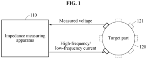
- FIG. 1 illustrates an example of an impedance measuring apparatus and a target part.
- an impedance measuring apparatus 110 may apply a high-frequency current and a low-frequency current to a target part 120 and measure a voltage of the target part 120.
- the impedance measuring apparatus 110 may measure an impedance of the target part 120 based on a current applied to the target part 120 and a voltage applied to the target part 120 in a state in which the current is applied to the target part 120.
- the target part 120 may correspond to body parts such as cells, tissues, nerves, a nerve bundle, and an organ of a living body, but is not limited thereto.
- the impedance of the target part 120 includes a bioimpedance of the target part 120.
- the impedance measuring apparatus 110 applies the current to the target part 120 using an electrode array including at least one electrode 121, and measures the voltage applied to the target part 120. Electrodes in the electrode array may be arranged to surround the target part 120. The impedance measuring apparatus 110 may select a first set of electrodes from the plurality of electrodes, and applies the current to the target part 120 using the selected first set of electrodes. Additionally, the impedance measuring apparatus 110 may select a second set of electrodes from the remaining electrodes and measure the voltage from the target part 120 using the selected second set of electrodes.
- a current electrode an electrode that applies a current
- an electrode that measures a voltage is referred to as a voltage electrode.
- the impedance measuring apparatus 110 measures the impedance of the target part 120 through a rotation of the current electrode and the voltage electrode.
- the impedance measuring apparatus 110 measures the impedance of the target part 120 based on an electrical impedance tomography (EIT).
- EIT refers to technology for monitoring a difference of an impedance changing with time or frequency through multiple channels and imaging measured data so that the difference of the impedance is visually analyzed.
- the impedance measuring apparatus 110 surrounds a tissue to be measured with an electrode array, flows a sine-wave current, for example, a current stimulator in a predetermined interval, measures a voltage through multiple channels by turns, and measures an impedance for each section. Impedance values measured based on an electrode rotation are converted into images. When the images acquired through such processes are consecutively displayed according to time, a difference in tissue corresponding to a difference in impedance may be visually confirmed.
- the EIT technology monitors a difference in impedance changing with time or frequency.
- a scheme of monitoring a difference of impedance changing with time is referred to as a time difference (TD) ETI
- a scheme of monitoring a difference in impedance changing with frequency is referred to as a frequency difference (FD) ETI.
- the TD ETI may be used to observe a difference of impedance changing with time.
- the FD ETI may be performed when at least two different tissues are present in a monitoring target part and the tissues are to be visually differentiated and monitored based on a difference in a rate of change of impedance based on a frequency.
- the TD ETI may be used to monitor a difference that occurs in the size of lungs when the size of the lungs changes due to inhalation and exhalation.
- the FD ETI may be used to visually distinguish the cancer cell from the normal cells based on a rate of change of impedance which is different for each frequency.
- the TD ETI and the FD ETI may be used in combination.
- the combination of the TD ETI and the FD ETI may increase a resolution of an image.
- the TD ETI and the FD ETI may be generally used in combination.
- the FD ETI measures an impedance appearing at a low-frequency and an impedance appearing at a high-frequency through an electrode array in sequence, recodes an impedance difference for each position in a tissue, and images the impedance difference.
- a low-frequency measurement and a high-frequency measurement should be performed separately.
- the low-frequency may be 5 to 30 hertz (Hz) and the high-frequency may be 20 to 200k Hz.
- the high-frequency and the low-frequency may also be defined as other various values.
- a sine-wave current is used to measure an impedance.
- the sine-wave current may be generated to have a desired frequency component through a circuit including a Wein-bridge oscillator.
- an implantable electronic medicine system such as a brain nerve EIT to replace functional magnetic resonance imaging (fMRI) or a nerve bundle EIT to detect a neuronal active area due to behavior or stimulation, miniaturization of a product may be required.
- a low-frequency signal is generated based on a beat phenomenon, whereby a size of a passive element for sine-wave generation is significantly reduced.
- the impedance measuring apparatus 110 combines high-frequency currents and generates a low-frequency current by detecting an envelope from the combined current. This is because, when a signal having a frequency f1 is combined with a signal having a frequency f2, an envelope of the combined signal may have a frequency of
- the total volume of the high-frequency generators configured to generate such high-frequency currents is generally less than 1 cubic centimeter (cm 3 ) so as to be implanted into a human body.
- these high-frequency generators are implemented in a form of System on Chip (SoC), and the area of the chip may be implemented to be less than 25 square millimeters (mm 2 ).
- SoC System on Chip
- the impedance measuring apparatus 110 applies an electrical stimulus to a stimulation area in the target part 120 using high-frequency currents.
- the impedance measuring apparatus 110 performs an operation for measuring an impedance of a target part in an impedance measurement mode and performs an operation for simulating a stimulation area in a selective stimulation mode.
- a low-frequency current may be suitable for applying a stimulus to a body part because the low-frequency current exerts a greater influence on the body part than the high-frequency current.
- a low-frequency envelope due to the beat phenomenon may occur in a predetermined area in which the high-frequency currents overlap.
- the area in which the high-frequency currents overlap in the target part 120 is referred to as a stimulation area.
- a database including areas in which a low-frequency electrical stimulation occurs due to electrodes to which the high-frequency currents are applied, or areas in which a low-frequency electrical stimulation occurs due to frequencies applied to the high-frequency currents and the electrodes to which the high-frequency currents are applied may be built in advance.
- the database stores electrodes matching stimulation areas, or stores electrodes, high-frequencies, and stimulation areas matching each other.
- the database stores information indicating that an electrical stimulus is applied to a first stimulation area when high-frequency currents are applied to a first electrode pair, and an electrical stimulus is applied to a second stimulation area when high-frequency currents are applied to a second electrode pair. Additionally, the database stores information indicating that an electrical stimulus is applied to a first stimulation area when a high-frequency current of a first frequency and a high-frequency current of a second frequency are applied to the first electrode pair and an electrical stimulus is applied to the second stimulation area when the high-frequency current of the second frequency and a high-frequency current of a third frequency are applied to the second electrode pair.
- the impedance measuring apparatus 110 determines a stimulation area to which the electrical stimulus is applied, and determines electrodes corresponding to the determined stimulation area or electrodes and frequencies corresponding to the determined stimulation area based on the database.
- the impedance measuring apparatus 110 determines a stimulation area based on an impedance measurement result. For example, the impedance measuring apparatus 110 determines an area where a stimulation is required to be the stimulation area based on the impedance measurement result. When the impedance measurement result indicates that that the stimulation is required in a first area in a nerve bundle, the impedance measuring apparatus 110 determines the first area to be the stimulation area, and selects appropriate electrodes or appropriate electrodes and frequencies such that a stimulus is applied to the first area.
- An electrode array and a high-frequency current generator are elements used for the impedance measurement. Since the electrical stimulation is performed using the electrode array and the high-frequency current generator, applicability of configurations for the impedance measuring apparatus 110 may be maximized.
- FIG. 2 illustrates an example of a rotation process for impedance measurement in accordance with one or more embodiments.
- FIG. 2 illustrates a current generator I and a biopotential measurer V arranged based on a time t. Electrodes of an electrode array are arranged to surround a target part. To measure an impedance of the target part, the current generator I and the biopotential measurer V are connected by changing the electrodes. The current generator I and the biopotential measurer V are connected to all possible combinations of electrode pairs in rotation.
- a rotation for voltage electrodes may be conducted while the current electrode is fixed.
- the current electrode is changed to another current electrode so that the rotation for the voltage electrodes is conducted while the other current electrode is fixed.
- an impedance of the target part is calculated based on voltage values collected during the process. The calculated impedance may be imaged and provided to a user.
- t t ij , i being a current electrode and j being a voltage electrode.
- t t 1j
- a voltage of the target part may be measured based on multiple channels.
- FIG. 2 illustrates a three-channel measurement process of Ch0 through Ch2. Depending on an example, a number of channels for voltage measurement may be selected in various ways.
- FIG. 3 illustrates an example of a process of generating a low-frequency signal using a beat phenomenon, in accordance with one or more embodiments.
- a first high-frequency current generator 310 generates a first high-frequency current 315 and a second high-frequency current generator 320 generates a second high-frequency current 325.
- a beat current 305 is generated through a combination of the first high-frequency current 315 and the second high-frequency current 325.
- An envelope detector 335 generates a low-frequency current 307 by detecting an envelope from the beat current 305.
- the low-frequency current 307 is applied to an electrode 351.
- a voltage of a target part 330 is transferred to a biopotential measurer 340 through an electrode 352.
- an impedance measuring apparatus generates the beat current 305 including a low-frequency component using the high-frequency current generators 310 and 320 without need to use a separate low-frequency current generator, and measures a voltage of the target part 330 based on the low-frequency current 307 corresponding to the low-frequency component of the beat current 305.
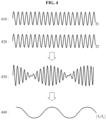
- FIG. 4 illustrates an example of waveforms of signals in a process of generating a low-frequency signal, in accordance with one or more embodiments.
- a high-frequency signal 410 may correspond to the first high-frequency current 315 of FIG. 3 and a high-frequency signal 420 may correspond to the second high-frequency current 325 of FIG. 3 .
- a frequency of the high-frequency signal 410 is denoted by f1 and a frequency of the high-frequency signal 420 is denoted by f2.
- a beat signal 430 may be generated.
- a low-frequency signal 440 is generated.
- the low-frequency signal 440 may correspond to the low-frequency current 307 of FIG.
- the impedance measuring apparatus generates high-frequency currents suitable for generating a desired low-frequency current. For example, the impedance measuring apparatus generates high-frequency currents having a frequency difference of f0 to generate a low-frequency current having a low-frequency of f0. The impedance measuring apparatus generates a beat current by combining the high-frequency currents having the frequency difference of f0 and uses an envelope of the beat current as a low-frequency current.
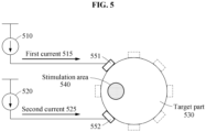
- FIGS. 5 and 6 illustrate examples of a process of applying an electrical stimulus to a stimulation area in accordance with one or more embodiments.
- an impedance measuring apparatus applies an electrical stimulus to a stimulation area 540 in a target part 530 using a first current 515 and a second current 525.
- a high-frequency current generator 510 generates the first current 515 corresponding to a first high-frequency
- a high-frequency current generator 520 generates the second current 525 corresponding to a second high-frequency.
- the impedance measuring apparatus may selects electrode 551 and 552 from an electrode array to apply an electrical stimulus to the stimulation area 540 in the target part 530, and applies the first current 515 and the second current 525 to the selected electrodes 551 and 552.
- the first current 515 and the second current 525 overlap in the stimulation area 540 such that a low-frequency electrical stimulus and a high-frequency electrical stimulus due to a beat phenomenon are induced to the stimulation area 540.
- the stimulation area 540 responds to the low-frequency electrical stimulus due to the beat phenomenon, but does not respond to the high-frequency electrical stimulus. Consequently, an effect like applying only the low-frequency electrical stimulus to the simulation area 540 is achieved.
- the low-frequency electrical stimulus corresponds to a difference between the first high-frequency and the second high-frequency.
- the impedance measuring apparatus selects the electrodes 551 and 552 by referencing a database built in advance. Additionally, the impedance measuring apparatus controls the high-frequency current generator 510 and the high-frequency current generator 520 such that the first current 515 and the second current 525 are generated at frequencies suitable for applying the electrical stimulus to the stimulation area 540.
- an impedance measuring apparatus applies an electrical stimulus to a stimulation area 640 in a target part 630 using a first current 615 and a second current 625.
- a position of the stimulation area 640 in FIG. 6 differs from a position of the stimulation area 540 in FIG. 5 .
- the impedance measuring apparatus may select electrodes 651 and 652, which are in positions different from the positions of the electrodes 551 and 552 of FIG. 5 from an electrode array, to stimulate the stimulation area 640, which is different from the stimulation area 540.
- the first current 615 and the second current 625 overlap in the stimulation area 640 such that a low-frequency electrical stimulus and a high-frequency electrical stimulus due to a beat phenomenon are induced to the stimulation area 640.
- the stimulation area 640 responds to the low-frequency electrical stimulus due to the beat phenomenon, but does not respond to the high-frequency electrical stimulus. Consequently, an effect like applying only the low-frequency electrical stimulus to the simulation area 640 is achieved.
- the impedance measuring apparatus may select the electrodes 651 and 652 by referencing a database built in advance, or may control the high-frequency current generator 610 and the high-frequency current generator 620 such that the first current 615 and the second current 625 are generated at frequencies suitable for applying the electrical stimulus to the stimulation area 640.
- the target parts 530 as illustrated in FIG. 5 and 630 as illustrated in FIG. 6 may correspond to nerve bundles, and the stimulation areas 540 as illustrated in FIG. 5 and 640 as illustrated in FIG. 6 may correspond to at least one nerve in the nerve bundles.
- the target parts 530 and 630 may correspond to sciatic nerves and the stimulation areas 540 and 640 may respectively correspond to a tibial nerve and a common peroneal nerve included in the sciatic nerves.
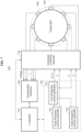
- FIG. 7 illustrates an example of an impedance measuring apparatus in accordance with one or more embodiments.
- an impedance measuring apparatus 700 includes a controller 710, a current generating circuit 720, an electrode switching network 730, a biopotential measurer 740, and an electrode array 760.
- the impedance measuring apparatus 700 measures a bioimpedance of a target part 750 or applies an electrical stimulus to a stimulation area in the target part 750.
- the current generating circuit 720 includes high-frequency current generators 721 and 722 and a low-frequency current generator 723.
- the high-frequency current generators 721 and 722 may generate currents based on a frequency corresponding to a command of the controller 710.
- the high-frequency current generator 721 may generate a first current corresponding to a first high-frequency f1 under a control of the controller 710.
- the high-frequency current generator 722 may generate a second current corresponding to a second high-frequency f2 under a control of the controller 710.
- the low-frequency current generator 723 may generate a low-frequency current corresponding to a difference
- the low-frequency current generator 723 may generate a beat current through a combination of the current of the first high-frequency f1 and the current of the second high-frequency f2, and generate the low-frequency current based on an envelope of the beat current.
- the electrode array 760 includes electrodes contacting the target part 750.
- the electrodes are arranged at intervals to surround the target part 750.
- the target part 750 may correspond to a nerve bundle, and the electrodes of the electrode array 760 may be arranged to surround the nerve bundle corresponding to the target part 750.
- the biopotential measurer 740 may measure a voltage applied to a target part based on a high-frequency current and a low-frequency current. For example, the biopotential measurer 740 measures a voltage applied to the target part 750 while a high-frequency current is applied to the target part 750 and measures a voltage applied to the target part 750 while a low-frequency current is applied to the target part 750.
- the controller 710 calculates an impedance of the target part 750 based on the voltage induced to the target part 750 by the high-frequency current and the low-frequency current.
- the high-frequency current may correspond to at least one of the first current corresponding to the first high-frequency f1 and the second current corresponding to the second high-frequency f2, and the low-frequency current may correspond to an envelope of the beat current corresponding to the frequency difference
- the electrode switching network 730 selectively connects at least one of the high-frequency current generator 721, the high-frequency current generator 722, the low-frequency current generator 723, and the biopotential measurer 740 to at least one of the electrodes of the electrode array 760 under the control of the controller 710.
- the electrode switching network 730 may connect the high-frequency current generator 721 and the low-frequency current generator 723 to the electrodes of the electrode array, so that a low-frequency current corresponding to a frequency of
- FIG. 7 illustrates that the first current corresponding to the high-frequency of f1 is provided in the impedance measurement mode, the second current corresponding to the high-frequency of f2 may also be provided instead of the first current corresponding to the high-frequency of f1.
- the controller 710 may select electrodes corresponding to the stimulation area from the plurality of electrodes included in the electrode array 760.
- the first current corresponding to the high-frequency of f1 and the second current corresponding to the high-frequency of f2 are applied to the selected electrodes, the first current and the second current overlap in the stimulation area such that a low-frequency electrical stimulus and a high-frequency electrical stimulus due to a beat phenomenon are induced to the stimulation area, and the stimulation area responds to the low-frequency electrical stimulus only.
- the electrode switching network 730 connects the high-frequency current generators 721 and 722 to the electrodes selected by the controller 710 such that the first current and the second current are applied to the selected electrodes.
- the controller 710 determines frequencies, for example, f1 and f2 by referencing a database or selecting electrodes corresponding to a stimulation area.
- FIG. 8 is a flowchart illustrating an example of an impedance measurement process based on an impedance measurement mode.
- the operations in FIG. 8 may be performed in the sequence and manner as shown, although the order of some operations may be changed or some of the operations omitted without departing from the spirit and scope of the illustrative examples described. Many of the operations shown in FIG. 8 may be performed in parallel or concurrently.
- One or more blocks of FIG. 8 , and combinations of the blocks, can be implemented by special purpose hardware-based computer that perform the specified functions, or combinations of special purpose hardware and computer instructions.
- FIGS. 1-7 are also applicable to FIG. 8 , and are incorporated herein by reference. Thus, the above description may not be repeated here.
- an impedance measuring apparatus determines whether an operation mode corresponds to an impedance measurement mode.
- operation 801 is performed.
- operation 900 as illustrated in FIG. 9 is performed. Operation 900 will be described with reference to FIG. 9 .
- the impedance measuring apparatus generates a first current corresponding to a first high-frequency in operation 801.
- the impedance measuring apparatus determines an electrode to which a current is to be applied, and applies the first current to the electrode in operation 802.
- the impedance measuring apparatus measures a voltage through a rotation of electrodes in operation 803. For example, when the first current is applied to a first electrode, the impedance measuring apparatus may measure a voltage through a rotation of electrodes other than the first electrode in an electrode array.
- the impedance measuring apparatus determines whether a rotation of current electrodes is terminated. When the rotation of current electrodes is not terminated, the impedance measuring apparatus changes an electrode to which a current is to be applied and applies the first current to the changed electrode in operation 805. Also, the impedance measuring apparatus may perform operations 803 and 804 again. Through this, such current application and voltage measurement based on the first current may be performed on all electrodes included in the electrode array.
- the impedance measuring apparatus When the rotation of current electrodes is terminated, the impedance measuring apparatus generates a second current corresponding to a second high-frequency in operation 806 and generates a low-frequency current based on a beat phenomenon of the first current and the second current in operation 807.
- the impedance measuring apparatus selects the first high-frequency and the second high-frequency such that a low-frequency current corresponding to a desired low-frequency is generated.
- Operations 808 through 811 may correspond to operations 802 through 805.
- the impedance measuring apparatus determines an electrode to which a current is to be applied and applies the low-frequency current to the electrode in operation 808.
- the impedance measuring apparatus measures a voltage through a rotation of electrodes in operation 809.
- the impedance measuring apparatus determines whether a rotation of current electrodes is terminated in operation 810. When the rotation of current electrodes is not terminated, the impedance measuring apparatus changes an electrode to which a current is to be applied and applies the low-frequency current to the changed electrode in operation 811. Additionally, the impedance measuring apparatus may perform operations 809 and 810 again. Through this, such current application and voltage measurement based on the low-frequency current may be performed on all electrodes included in the electrode array.
- the impedance measuring apparatus calculates an impedance in operation 812.
- the impedance measuring apparatus calculates a bioimpedance of the target part based on values of the measured voltage, the low-frequency current (an envelope of the beat current), and the first current.
- the description made with reference to FIGS. 1 through 7 is also applicable to the impedance measurement process.
- FIG. 9 is a flowchart illustrating a stimulation process based on a selective stimulation mode.
- the operations in FIG. 9 may be performed in the sequence and manner as shown, although the order of some operations may be changed or some of the operations omitted without departing from the spirit and scope of the illustrative examples described. Many of the operations shown in FIG. 9 may be performed in parallel or concurrently.
- One or more blocks of FIG. 9 , and combinations of the blocks, can be implemented by special purpose hardware-based computer that perform the specified functions, or combinations of special purpose hardware and computer instructions.
- FIGS. 1-8 are also applicable to FIG. 9 , and are incorporated herein by reference. Thus, the above description may not be repeated here.
- an impedance measuring apparatus determines whether an operation mode corresponds to a selective stimulation mode.
- operation 901 When the operation mode corresponds to the selective stimulation mode, operation 901 is performed.
- operation 800 As illustrated in FIG. 8 is performed.
- the impedance measuring apparatus generates a first current corresponding to a first high-frequency in operation 901.
- the impedance measuring apparatus generates a second current corresponding to a second high-frequency in operation 902.
- the impedance measuring apparatus determines electrodes for applying a current in operation 903.
- the impedance measuring apparatus applies the first current and the second current through the determined electrodes in operation 904.
- the first current and the second current When the first current and the second current are applied to the determined electrodes, the first current and the second current overlap in a stimulation area such that a low-frequency electrical stimulus and a high-frequency electrical stimulus due to a beat phenomenon are induced to the stimulation area, and the stimulation area responds to the low-frequency electrical stimulus only.
- the description made with reference to FIGS. 1 through 7 is also applicable to the stimulation process.
- the impedance measuring apparatus 110, the impedance measuring apparatus 700, the controller 710, the high frequency current generator 721, the high frequency current generator 722, the biopotential measurer 740, the low-frequency current generator 723, the electrode switching network 730, and other apparatuses, devices, and other components described herein with regard to FIGS. 1-9 are implemented by hardware components.
- hardware components that may be used to perform the operations described in this application where appropriate include controllers, sensors, generators, drivers, memories, comparators, arithmetic logic units, adders, subtractors, multipliers, dividers, integrators, and any other electronic components configured to perform the operations described in this application.
- one or more of the hardware components that perform the operations described in this application are implemented by computing hardware, for example, by one or more processors or computers.
- a processor or computer may be implemented by one or more processing elements, such as an array of logic gates, a controller and an arithmetic logic unit, a digital signal processor, a microcomputer, a programmable logic controller, a fieldprogrammable gate array, a programmable logic array, a microprocessor, or any other device or combination of devices that is configured to respond to and execute instructions in a defined manner to achieve a desired result.
- a processor or computer includes, or is connected to, one or more memories storing instructions or software that are executed by the processor or computer.
- Hardware components implemented by a processor or computer may execute instructions or software, such as an operating system (OS) and one or more software applications that run on the OS, to perform the operations described in this application.
- the hardware components may also access, manipulate, process, create, and store data in response to execution of the instructions or software.
- OS operating system
- processors or computers may be used, or a processor or computer may include multiple processing elements, or multiple types of processing elements, or both.
- a single hardware component or two or more hardware components may be implemented by a single processor, or two or more processors, or a processor and a controller.
- One or more hardware components may be implemented by one or more processors, or a processor and a controller, and one or more other hardware components may be implemented by one or more other processors, or another processor and another controller.
- One or more processors, or a processor and a controller may implement a single hardware component, or two or more hardware components.
- a hardware component may have any one or more of different processing configurations, examples of which include a single processor, independent processors, parallel processors, single-instruction single-data (SISD) multiprocessing, single-instruction multiple-data (SIMD) multiprocessing, multiple-instruction single-data (MISO) multiprocessing, and multiple-instruction multiple-data (MIMD) multiprocessing.
- SISD single-instruction single-data
- SIMD single-instruction multiple-data
- MIMD multiple-instruction multiple-data
- FIGS. 1-9 that perform the operations described in this application are performed by computing hardware, for example, by one or more processors or computers, implemented as described above executing instructions or software to perform the operations described in this application that are performed by the methods.
- a single operation or two or more operations may be performed by a single processor, or two or more processors, or a processor and a controller.
- One or more operations may be performed by one or more processors, or a processor and a controller, and one or more other operations may be performed by one or more other processors, or another processor and another controller.
- One or more processors, or a processor and a controller may perform a single operation, or two or more operations.
- Instructions or software to control computing hardware may be written as computer programs, code segments, instructions or any combination thereof, for individually or collectively instructing or configuring the one or more processors or computers to operate as a machine or special-purpose computer to perform the operations performed by the hardware components and the methods as described above.
- the instructions or software include machine code that is directly executed by the one or more processors or computers, such as machine code produced by a compiler.
- the instructions or software include higher-level code that is executed by the one or more processors or computers using an interpreter.
- the instructions or software may be written using any programming language based on the block diagrams and the flow charts illustrated in the drawings and the corresponding descriptions in the specification, which disclose algorithms for performing the operations performed by the hardware components and the methods as described above.
- the instructions or software to control computing hardware for example, one or more processors or computers, to implement the hardware components and perform the methods as described above, and any associated data, data files, and data structures, may be recorded, stored, or fixed in or on one or more non-transitory computer-readable storage media.
- Examples of a non-transitory computer-readable storage medium include read-only memory (ROM), random-access programmable read only memory (PROM), electrically erasable programmable read-only memory (EEPROM), random-access memory (RAM), dynamic random access memory (DRAM), static random access memory (SRAM), flash memory, non-volatile memory, CD-ROMs, CD-Rs, CD+Rs, CD-RWs, CD+RWs, DVD-ROMs, DVD-Rs, DVD+Rs, DVD-RWs, DVD+RWs, DVD-RAMs, BD-ROMs, BD-Rs, BD-R LTHs, BD-Res as non-limiting, blue-ray or optical disk storage examples, hard disk drive (HDD), solid state drive (SSD), flash memory, a card type memory such as multimedia card micro or a card (for example, secure digital (SD) or extreme digital (XD)), magnetic tapes, floppy disks, magneto-optical data storage devices, optical data storage devices
- the instructions or software and any associated data, data files, and data structures are distributed over network-coupled computer systems so that the instructions and software and any associated data, data files, and data structures are stored, accessed, and executed in a distributed fashion by the one or more processors or computers.
Landscapes
- Health & Medical Sciences (AREA)
- Life Sciences & Earth Sciences (AREA)
- Animal Behavior & Ethology (AREA)
- Veterinary Medicine (AREA)
- Public Health (AREA)
- Engineering & Computer Science (AREA)
- Biomedical Technology (AREA)
- General Health & Medical Sciences (AREA)
- Nuclear Medicine, Radiotherapy & Molecular Imaging (AREA)
- Heart & Thoracic Surgery (AREA)
- Biophysics (AREA)
- Radiology & Medical Imaging (AREA)
- Physics & Mathematics (AREA)
- Pathology (AREA)
- Medical Informatics (AREA)
- Molecular Biology (AREA)
- Surgery (AREA)
- Neurology (AREA)
- Neurosurgery (AREA)
- Measurement And Recording Of Electrical Phenomena And Electrical Characteristics Of The Living Body (AREA)
- Electrotherapy Devices (AREA)
- Measurement Of Resistance Or Impedance (AREA)
Claims (11)
- Impedanzmessgerät umfassend:einen ersten Hochfrequenzstromgenerator (721) konfiguriert, um einen ersten Strom entsprechend einer ersten Hochfrequenz zu erzeugen;einen zweiten Hochfrequenzstromgenerator (722) konfiguriert, um einen zweiten Strom entsprechend einer zweiten Hochfrequenz zu erzeugen;einen Niederfrequenzstromgenerator (723) konfiguriert, um einen Niederfrequenzstrom basierend auf einem Beat-Phänomen des ersten Stroms und des zweiten Stroms zu erzeugen;einen Biopotentialmesser (740) konfiguriert, um eine an das Zielobjekt angelegte Spannung basierend auf dem hochfrequenten Strom und dem niederfrequenten Strom zu messen;eine Elektrodenanordnung (760) umfassend eine Vielzahl von Elektroden, die so konfiguriert sind, dass sie das Zielobjekt (750) kontaktieren;ein Elektrodenschaltnetzwerk (730) konfiguriert, um selektiv mindestens einen des ersten Hochfrequenzstromgenerators (721), des zweiten Hochfrequenzstromgenerators (722) und des Niederfrequenzstromgenerators (723) mit mindestens einer der Vielzahl von Elektroden (760) zu verbinden; undeine Steuerung (710) konfiguriert, um eine Impedanz eines Zielobjekts basierend auf einer Spannung zu berechnen, die in dem Zielobjekt durch einen Hochfrequenzstrom induziert wird, der mindestens einem von dem ersten Strom und dem zweiten Strom und dem Niederfrequenzstrom entspricht,wobei, wenn ein Stimulationsbereich in dem Zielobjekt ausgewählt wird, die Steuerung (710) weiterhin konfiguriert ist, um eine oder mehrere Elektroden, die dem Stimulationsbereich entsprechen, aus der Vielzahl von Elektroden auszuwählen.
- Vorrichtung nach Anspruch 1, wobei das Zielobjekt (750) einem Nervenbündel entspricht und die Vielzahl von Elektroden (760) so angeordnet ist, dass sie das Nervenbündel umgeben.
- Vorrichtung nach Anspruch 1 oder 2, wobei der Niederfrequenzstromgenerator (723) konfiguriert ist, um den Niederfrequenzstrom basierend auf einer Einhüllenden eines kombinierten Stroms des ersten Stroms und des zweiten Stroms zu erzeugen.
- Vorrichtung nach einem der Ansprüche 1 bis 3, wobei der Niederfrequenzstrom eine Niederfrequenz entsprechend einer Differenz zwischen der ersten Hochfrequenz und der zweiten Hochfrequenz aufweist.
- Vorrichtung nach Anspruch 1, wobei, wenn der erste Strom und der zweite Strom an eine oder mehreren der ausgewählten Elektroden angelegt werden, sich der erste Strom und der zweite Strom in dem Stimulationsbereich überlappen, um einen niederfrequenten elektrischen Reiz in dem Stimulationsbereich basierend auf einem Beat-Phänomen zu induzieren; oder
wobei das Zielobjekt (750) einem Nervenbündel entspricht und der Stimulationsbereich mindestens einem Nerv in dem Nervenbündel entspricht. - Impedanzmessverfahren, umfassend:Erzeugen (801) eines ersten Stroms entsprechend einer ersten Hochfrequenz;Erzeugen (806) eines zweiten Stroms entsprechend einer zweiten Hochfrequenz;Erzeugen (807) eines Niederfrequenzstroms basierend auf einem Beat-Phänomen des ersten Stroms und des zweiten Stroms;Messen einer an das Zielobjekt (750) angelegten Spannung basierend auf dem Hochfrequenzstrom und dem Niederfrequenzstrom;selektives Verbinden von mindestens einem von einem ersten Hochfrequenzstromgenerator (721), der konfiguriert ist, um den ersten Strom zu erzeugen, einem zweiten Hochfrequenzstromgenerator (722), der konfiguriert ist, um den zweiten Strom zu erzeugen, und einem Niederfrequenzstromgenerator (723), der konfiguriert ist, um den Niederfrequenzstrom zu erzeugen, mit mindestens einer von Elektroden (760), die das Zielobjekt (750) kontaktieren; undBerechnen (812) einer Impedanz eines Zielobjekts (750) basierend auf einer Spannung, die an dem Zielobjekt (750) durch einen Hochfrequenzstrom entsprechend mindestens einem von dem ersten Strom und dem zweiten Strom und dem Niederfrequenzstrom induziert wird,wobei das Verfahren ferner das Auswählen einer oder mehrerer Elektroden entsprechend einem Stimulationsbereich aus einer Vielzahl von Elektroden umfasst, die so konfiguriert sind, dass sie das Zielobjekt kontaktieren, wenn der Stimulationsbereich in dem Zielobjekt (750) ausgewählt wird.
- Impedanzmessverfahren nach Anspruch 6, wobei das Zielobjekt (750) einem Nervenbündel entspricht, und die Elektroden (760) so angeordnet sind, dass sie das Nervenbündel umgeben.
- Impedanzmessverfahren nach Anspruch 6 oder 7 ferner umfassend das Erzeugen eines Beat-Stroms durch Erzeugen des Niederfrequenzstroms basierend auf einer Einhüllenden eines kombinierten Stroms des ersten Stroms und des zweiten Stroms.
- Impedanzmessverfahren nach einem der Ansprüche 6 bis 8, wobei der Niederfrequenzstrom eine Niederfrequenz aufweist, die einer Differenz zwischen der ersten Hochfrequenz und der zweiten Hochfrequenz entspricht; oderwobei, wenn der erste Strom und der zweite Strom an die ausgewählten Elektroden angelegt werden, sich der erste Strom und der zweite Strom in dem Stimulationsbereich überlappen, um einen niederfrequenten elektrischen Reiz in dem Stimulationsbereich basierend auf einem Beat-Phänomen zu induzieren; oderwobei das Zielobjekt (750) einem Nervenbündel entspricht und der Stimulationsbereich mindestens einem Nerv in dem Nervenbündel entspricht.
- Elektronisches Gerät umfassend das Impedanzmessgerät nach einem der Ansprüche 1 bis 5, wobei das elektronische Gerät ferner eine Vielzahl von Elektroden umfasst, die so konfiguriert sind, dass sie einen Körperteil kontaktieren, und
wobei die Steuerung (710) ferner konfiguriert ist, um aus der Vielzahl von Elektroden die Elektroden auszuwählen, an die der erste Hochfrequenzstrom und der zweite Hochfrequenzstrom angelegt werden sollen. - Elektronisches Gerät nach Anspruch 10, wobei die erste Hochfrequenz und die zweite Hochfrequenz im Bereich von 20 bis 200 Kilohertz (KHz) liegen; oderwobei die Niederfrequenz im Bereich von 5 bis 30 Hertz, Hz, liegt; oderwobei das Gesamtvolumen des ersten Hochfrequenzstromgenerators (721), des zweiten Hochfrequenzstromgenerators (722) und des Niederfrequenzstromgenerators (723) weniger als 1 Kubikzentimeter (cm3) beträgt; oderwobei der erste Hochfrequenzstromgenerator (721) und der zweite Hochfrequenzstromgenerator (722) als ein Chip konfiguriert sind und die Fläche des Chips weniger als 25 Quadratmillimeter (mm2) beträgt; oderwobei ein Modus, in dem die Steuereinheit (710) den ersten Hochfrequenzstrom und den zweiten Hochfrequenzstrom an die ausgewählten Elektroden anlegt, ein Stimulationsmodus ist, undwobei das Steuergerät (710) einen Messmodus zum Anlegen des Niederfrequenzstroms aufweist.
Applications Claiming Priority (2)
| Application Number | Priority Date | Filing Date | Title |
|---|---|---|---|
| KR20180162168 | 2018-12-14 | ||
| KR1020190108798A KR102896238B1 (ko) | 2018-12-14 | 2019-09-03 | 생체 임피던스 측정 및 전기 자극을 위한 장치 및 방법 |
Publications (2)
| Publication Number | Publication Date |
|---|---|
| EP3666183A1 EP3666183A1 (de) | 2020-06-17 |
| EP3666183B1 true EP3666183B1 (de) | 2023-08-30 |
Family
ID=68808148
Family Applications (1)
| Application Number | Title | Priority Date | Filing Date |
|---|---|---|---|
| EP19214087.9A Active EP3666183B1 (de) | 2018-12-14 | 2019-12-06 | Bioimpedanzmessverfahren und vorrichtung mit elektrischer stimulation |
Country Status (4)
| Country | Link |
|---|---|
| US (2) | US11623094B2 (de) |
| EP (1) | EP3666183B1 (de) |
| JP (1) | JP7348049B2 (de) |
| CN (1) | CN111317471B (de) |
Families Citing this family (6)
| Publication number | Priority date | Publication date | Assignee | Title |
|---|---|---|---|---|
| JP7767288B2 (ja) | 2019-12-23 | 2025-11-11 | アリメトリー リミテッド | 電極パッチおよび接続システム |
| DE102020119907A1 (de) | 2020-07-28 | 2022-02-03 | Enari GmbH | Vorrichtung und Verfahren zur Erkennung und Vorhersage von Körperbewegungen |
| CN114712709A (zh) * | 2022-05-10 | 2022-07-08 | 杭州思为谷医疗科技有限公司 | 一种带电极定位功能的经颅电刺激系统及方法 |
| WO2025019389A1 (en) * | 2023-07-14 | 2025-01-23 | President And Fellows Of Harvard College | Bioelectrical and bioimpedance measurement using shared electrodes |
| CN117282024B (zh) * | 2023-09-22 | 2024-05-14 | 赛福凯尔(绍兴)医疗科技有限公司 | 电场发射系统 |
| CN120037578B (zh) * | 2025-02-21 | 2025-11-11 | 北京领创医谷科技发展有限责任公司 | 用于测量电极阻抗的系统和方法以及评估电极健康度的方法 |
Family Cites Families (17)
| Publication number | Priority date | Publication date | Assignee | Title |
|---|---|---|---|---|
| JP2000184726A (ja) | 1998-12-18 | 2000-06-30 | Central Res Inst Of Electric Power Ind | 直流−交流電力変換方法及びその装置 |
| EP1246665B1 (de) * | 2000-01-07 | 2005-08-24 | Biowave Corporation | Vorrichtung zur elektrotherapie |
| US8788044B2 (en) * | 2005-01-21 | 2014-07-22 | Michael Sasha John | Systems and methods for tissue stimulation in medical treatment |
| JP2008536650A (ja) | 2005-04-21 | 2008-09-11 | エピ‐サイ,リミテッド・ライアビリティ・カンパニー | 前癌組織および癌組織並びに上皮組織における電気生理学的変化を検出する方法およびシステム |
| US8515551B2 (en) * | 2006-03-14 | 2013-08-20 | Donald A. Rhodes | Diagnostic method and apparatus |
| CN101108266A (zh) * | 2006-07-18 | 2008-01-23 | 深圳职业技术学院 | 骨愈合治疗仪和骨愈合治疗方法 |
| GB0709834D0 (en) | 2007-05-22 | 2007-07-04 | Gillbe Ivor S | Array stimulator |
| US9061148B2 (en) | 2011-09-22 | 2015-06-23 | Djo, Llc | Devices, systems and methods for treating pain with electrical stimulation |
| JP5235040B1 (ja) | 2012-06-26 | 2013-07-10 | 株式会社白寿生科学研究所 | 電位治療装置 |
| DE102012214786B4 (de) | 2012-08-20 | 2025-08-14 | Drägerwerk AG & Co. KGaA | Vorrichtung zur Bestimmung der regionalen Verteilung eines Maßes für die Lungenperfusion |
| EP2944253A4 (de) | 2013-01-09 | 2016-08-24 | Timpel Sa | Verfahren und vorrichtung zur signalerfassung für elektrische impedanztomografie |
| CA2945483A1 (en) | 2013-04-08 | 2014-10-16 | Biowave Corp. | Noninvasive or percutaneous nerve stimulation |
| US9804112B2 (en) * | 2013-11-20 | 2017-10-31 | Transtech Systems, Inc. | Selective characterization of material under test (MUT) with electromagnetic impedance tomography and spectroscopy |
| KR101490811B1 (ko) | 2013-12-04 | 2015-02-06 | 주식회사 케이헬쓰웨어 | 전기임피던스 단층 촬영장치 |
| GB201506760D0 (en) * | 2015-04-21 | 2015-06-03 | Ucl Business Plc | Detecting activity in peripheral nerves |
| US9630012B2 (en) | 2015-08-06 | 2017-04-25 | Meagan Medical, Inc. | Spinal cord stimulation with interferential current |
| KR101747029B1 (ko) | 2016-04-01 | 2017-06-27 | 경희대학교 산학협력단 | 전류를 주입 없이 mri를 이용한 저주파 전도도 영상 복원 장치 및 그 방법 |
-
2019
- 2019-10-17 US US16/655,596 patent/US11623094B2/en active Active
- 2019-12-06 EP EP19214087.9A patent/EP3666183B1/de active Active
- 2019-12-09 CN CN201911248416.4A patent/CN111317471B/zh active Active
- 2019-12-11 JP JP2019223616A patent/JP7348049B2/ja active Active
-
2023
- 2023-03-07 US US18/118,376 patent/US11992683B2/en active Active
Also Published As
| Publication number | Publication date |
|---|---|
| JP2020093101A (ja) | 2020-06-18 |
| EP3666183A1 (de) | 2020-06-17 |
| CN111317471B (zh) | 2024-07-12 |
| CN111317471A (zh) | 2020-06-23 |
| JP7348049B2 (ja) | 2023-09-20 |
| US20230218902A1 (en) | 2023-07-13 |
| US11992683B2 (en) | 2024-05-28 |
| US20200188676A1 (en) | 2020-06-18 |
| US11623094B2 (en) | 2023-04-11 |
Similar Documents
| Publication | Publication Date | Title |
|---|---|---|
| EP3666183B1 (de) | Bioimpedanzmessverfahren und vorrichtung mit elektrischer stimulation | |
| Aristovich et al. | Imaging fast electrical activity in the brain with electrical impedance tomography | |
| Soekadar et al. | In vivo assessment of human brain oscillations during application of transcranial electric currents | |
| US8494627B2 (en) | Neurocranial electrostimulation models, systems, devices, and methods | |
| US20190059778A1 (en) | Methods for detecting a condition | |
| von Conta et al. | Benchmarking the effects of transcranial temporal interference stimulation (tTIS) in humans | |
| JP2016540536A (ja) | 多部位経頭蓋電流刺激、コンピュータ可読媒体、およびコンピュータプログラムの構成を最適化する方法およびシステム | |
| JP2018516150A (ja) | 脳神経活動の監視 | |
| Lascano et al. | Surgically relevant localization of the central sulcus with high-density somatosensory-evoked potentials compared with functional magnetic resonance imaging | |
| Bera | Noninvasive electromagnetic methods for brain monitoring: a technical review | |
| Bangera et al. | Experimental validation of the influence of white matter anisotropy on the intracranial EEG forward solution | |
| CN112534279B (zh) | 用于估计介质的物理参数的系统及方法 | |
| Gomez–Tames et al. | TMS activation site estimation using multiscale realistic head models | |
| Papanicolaou | Clinical magnetoencephalography and magnetic source imaging | |
| Hannan et al. | Imaging slow brain activity during neocortical and hippocampal epileptiform events with electrical impedance tomography | |
| KR102896238B1 (ko) | 생체 임피던스 측정 및 전기 자극을 위한 장치 및 방법 | |
| Canna et al. | Brain fMRI during orientation selective epidural spinal cord stimulation | |
| US11273310B2 (en) | Systems and methods for predicting optimal deep brain stimulation parameters | |
| Tanabe et al. | Activation site estimation using induced current simulation and motor evoked potential latency in transcranial magnetic stimulation | |
| Sehatpour et al. | Advanced Methodology for Neurophysiological Analysis and Biomarker Development: Time–Frequency and Source-Localization Approaches | |
| Walckiers | Bio-electromagnetic model of deep brain stimulation | |
| Antonakakis | The effect of experimental and modeling parameters on combined EEG/MEG source analysis and transcranial electric stimulation optimization of somatosensory and epilepsy activity | |
| KR102909922B1 (ko) | 음파공명진동을 이용한 뇌신경 자극 장치 및 방법 | |
| Witkowska-Wrobel | Imaging physiological brain activity and epilepsy with Electrical Impedance Tomography | |
| Lombardi | Valutazione comparativa degli algoritmi che costituiscono lo stato dell’arte nel rilevamento di up state in registrazioni intracorticali in vivo. |
Legal Events
| Date | Code | Title | Description |
|---|---|---|---|
| PUAI | Public reference made under article 153(3) epc to a published international application that has entered the european phase |
Free format text: ORIGINAL CODE: 0009012 |
|
| STAA | Information on the status of an ep patent application or granted ep patent |
Free format text: STATUS: THE APPLICATION HAS BEEN PUBLISHED |
|
| AK | Designated contracting states |
Kind code of ref document: A1 Designated state(s): AL AT BE BG CH CY CZ DE DK EE ES FI FR GB GR HR HU IE IS IT LI LT LU LV MC MK MT NL NO PL PT RO RS SE SI SK SM TR |
|
| AX | Request for extension of the european patent |
Extension state: BA ME |
|
| STAA | Information on the status of an ep patent application or granted ep patent |
Free format text: STATUS: REQUEST FOR EXAMINATION WAS MADE |
|
| 17P | Request for examination filed |
Effective date: 20201217 |
|
| RBV | Designated contracting states (corrected) |
Designated state(s): AL AT BE BG CH CY CZ DE DK EE ES FI FR GB GR HR HU IE IS IT LI LT LU LV MC MK MT NL NO PL PT RO RS SE SI SK SM TR |
|
| GRAP | Despatch of communication of intention to grant a patent |
Free format text: ORIGINAL CODE: EPIDOSNIGR1 |
|
| STAA | Information on the status of an ep patent application or granted ep patent |
Free format text: STATUS: GRANT OF PATENT IS INTENDED |
|
| INTG | Intention to grant announced |
Effective date: 20230425 |
|
| P01 | Opt-out of the competence of the unified patent court (upc) registered |
Effective date: 20230519 |
|
| GRAS | Grant fee paid |
Free format text: ORIGINAL CODE: EPIDOSNIGR3 |
|
| GRAA | (expected) grant |
Free format text: ORIGINAL CODE: 0009210 |
|
| STAA | Information on the status of an ep patent application or granted ep patent |
Free format text: STATUS: THE PATENT HAS BEEN GRANTED |
|
| AK | Designated contracting states |
Kind code of ref document: B1 Designated state(s): AL AT BE BG CH CY CZ DE DK EE ES FI FR GB GR HR HU IE IS IT LI LT LU LV MC MK MT NL NO PL PT RO RS SE SI SK SM TR |
|
| REG | Reference to a national code |
Ref country code: GB Ref legal event code: FG4D |
|
| REG | Reference to a national code |
Ref country code: CH Ref legal event code: EP |
|
| REG | Reference to a national code |
Ref country code: DE Ref legal event code: R096 Ref document number: 602019036047 Country of ref document: DE |
|
| REG | Reference to a national code |
Ref country code: IE Ref legal event code: FG4D |
|
| REG | Reference to a national code |
Ref country code: LT Ref legal event code: MG9D |
|
| REG | Reference to a national code |
Ref country code: NL Ref legal event code: MP Effective date: 20230830 |
|
| REG | Reference to a national code |
Ref country code: AT Ref legal event code: MK05 Ref document number: 1604328 Country of ref document: AT Kind code of ref document: T Effective date: 20230830 |
|
| PG25 | Lapsed in a contracting state [announced via postgrant information from national office to epo] |
Ref country code: GR Free format text: LAPSE BECAUSE OF FAILURE TO SUBMIT A TRANSLATION OF THE DESCRIPTION OR TO PAY THE FEE WITHIN THE PRESCRIBED TIME-LIMIT Effective date: 20231201 |
|
| PG25 | Lapsed in a contracting state [announced via postgrant information from national office to epo] |
Ref country code: IS Free format text: LAPSE BECAUSE OF FAILURE TO SUBMIT A TRANSLATION OF THE DESCRIPTION OR TO PAY THE FEE WITHIN THE PRESCRIBED TIME-LIMIT Effective date: 20231230 |
|
| PG25 | Lapsed in a contracting state [announced via postgrant information from national office to epo] |
Ref country code: SE Free format text: LAPSE BECAUSE OF FAILURE TO SUBMIT A TRANSLATION OF THE DESCRIPTION OR TO PAY THE FEE WITHIN THE PRESCRIBED TIME-LIMIT Effective date: 20230830 Ref country code: RS Free format text: LAPSE BECAUSE OF FAILURE TO SUBMIT A TRANSLATION OF THE DESCRIPTION OR TO PAY THE FEE WITHIN THE PRESCRIBED TIME-LIMIT Effective date: 20230830 Ref country code: NO Free format text: LAPSE BECAUSE OF FAILURE TO SUBMIT A TRANSLATION OF THE DESCRIPTION OR TO PAY THE FEE WITHIN THE PRESCRIBED TIME-LIMIT Effective date: 20231130 Ref country code: LV Free format text: LAPSE BECAUSE OF FAILURE TO SUBMIT A TRANSLATION OF THE DESCRIPTION OR TO PAY THE FEE WITHIN THE PRESCRIBED TIME-LIMIT Effective date: 20230830 Ref country code: LT Free format text: LAPSE BECAUSE OF FAILURE TO SUBMIT A TRANSLATION OF THE DESCRIPTION OR TO PAY THE FEE WITHIN THE PRESCRIBED TIME-LIMIT Effective date: 20230830 Ref country code: IS Free format text: LAPSE BECAUSE OF FAILURE TO SUBMIT A TRANSLATION OF THE DESCRIPTION OR TO PAY THE FEE WITHIN THE PRESCRIBED TIME-LIMIT Effective date: 20231230 Ref country code: HR Free format text: LAPSE BECAUSE OF FAILURE TO SUBMIT A TRANSLATION OF THE DESCRIPTION OR TO PAY THE FEE WITHIN THE PRESCRIBED TIME-LIMIT Effective date: 20230830 Ref country code: GR Free format text: LAPSE BECAUSE OF FAILURE TO SUBMIT A TRANSLATION OF THE DESCRIPTION OR TO PAY THE FEE WITHIN THE PRESCRIBED TIME-LIMIT Effective date: 20231201 Ref country code: FI Free format text: LAPSE BECAUSE OF FAILURE TO SUBMIT A TRANSLATION OF THE DESCRIPTION OR TO PAY THE FEE WITHIN THE PRESCRIBED TIME-LIMIT Effective date: 20230830 Ref country code: AT Free format text: LAPSE BECAUSE OF FAILURE TO SUBMIT A TRANSLATION OF THE DESCRIPTION OR TO PAY THE FEE WITHIN THE PRESCRIBED TIME-LIMIT Effective date: 20230830 |
|
| PG25 | Lapsed in a contracting state [announced via postgrant information from national office to epo] |
Ref country code: PL Free format text: LAPSE BECAUSE OF FAILURE TO SUBMIT A TRANSLATION OF THE DESCRIPTION OR TO PAY THE FEE WITHIN THE PRESCRIBED TIME-LIMIT Effective date: 20230830 Ref country code: NL Free format text: LAPSE BECAUSE OF FAILURE TO SUBMIT A TRANSLATION OF THE DESCRIPTION OR TO PAY THE FEE WITHIN THE PRESCRIBED TIME-LIMIT Effective date: 20230830 |
|
| PG25 | Lapsed in a contracting state [announced via postgrant information from national office to epo] |
Ref country code: ES Free format text: LAPSE BECAUSE OF FAILURE TO SUBMIT A TRANSLATION OF THE DESCRIPTION OR TO PAY THE FEE WITHIN THE PRESCRIBED TIME-LIMIT Effective date: 20230830 |
|
| PG25 | Lapsed in a contracting state [announced via postgrant information from national office to epo] |
Ref country code: SM Free format text: LAPSE BECAUSE OF FAILURE TO SUBMIT A TRANSLATION OF THE DESCRIPTION OR TO PAY THE FEE WITHIN THE PRESCRIBED TIME-LIMIT Effective date: 20230830 Ref country code: RO Free format text: LAPSE BECAUSE OF FAILURE TO SUBMIT A TRANSLATION OF THE DESCRIPTION OR TO PAY THE FEE WITHIN THE PRESCRIBED TIME-LIMIT Effective date: 20230830 Ref country code: ES Free format text: LAPSE BECAUSE OF FAILURE TO SUBMIT A TRANSLATION OF THE DESCRIPTION OR TO PAY THE FEE WITHIN THE PRESCRIBED TIME-LIMIT Effective date: 20230830 Ref country code: EE Free format text: LAPSE BECAUSE OF FAILURE TO SUBMIT A TRANSLATION OF THE DESCRIPTION OR TO PAY THE FEE WITHIN THE PRESCRIBED TIME-LIMIT Effective date: 20230830 Ref country code: DK Free format text: LAPSE BECAUSE OF FAILURE TO SUBMIT A TRANSLATION OF THE DESCRIPTION OR TO PAY THE FEE WITHIN THE PRESCRIBED TIME-LIMIT Effective date: 20230830 Ref country code: CZ Free format text: LAPSE BECAUSE OF FAILURE TO SUBMIT A TRANSLATION OF THE DESCRIPTION OR TO PAY THE FEE WITHIN THE PRESCRIBED TIME-LIMIT Effective date: 20230830 Ref country code: SK Free format text: LAPSE BECAUSE OF FAILURE TO SUBMIT A TRANSLATION OF THE DESCRIPTION OR TO PAY THE FEE WITHIN THE PRESCRIBED TIME-LIMIT Effective date: 20230830 Ref country code: PT Free format text: LAPSE BECAUSE OF FAILURE TO SUBMIT A TRANSLATION OF THE DESCRIPTION OR TO PAY THE FEE WITHIN THE PRESCRIBED TIME-LIMIT Effective date: 20240102 |
|
| PG25 | Lapsed in a contracting state [announced via postgrant information from national office to epo] |
Ref country code: IT Free format text: LAPSE BECAUSE OF FAILURE TO SUBMIT A TRANSLATION OF THE DESCRIPTION OR TO PAY THE FEE WITHIN THE PRESCRIBED TIME-LIMIT Effective date: 20230830 |
|
| REG | Reference to a national code |
Ref country code: DE Ref legal event code: R097 Ref document number: 602019036047 Country of ref document: DE |
|
| PLBE | No opposition filed within time limit |
Free format text: ORIGINAL CODE: 0009261 |
|
| STAA | Information on the status of an ep patent application or granted ep patent |
Free format text: STATUS: NO OPPOSITION FILED WITHIN TIME LIMIT |
|
| PG25 | Lapsed in a contracting state [announced via postgrant information from national office to epo] |
Ref country code: SI Free format text: LAPSE BECAUSE OF FAILURE TO SUBMIT A TRANSLATION OF THE DESCRIPTION OR TO PAY THE FEE WITHIN THE PRESCRIBED TIME-LIMIT Effective date: 20230830 |
|
| REG | Reference to a national code |
Ref country code: CH Ref legal event code: PL |
|
| 26N | No opposition filed |
Effective date: 20240603 |
|
| PG25 | Lapsed in a contracting state [announced via postgrant information from national office to epo] |
Ref country code: LU Free format text: LAPSE BECAUSE OF NON-PAYMENT OF DUE FEES Effective date: 20231206 |
|
| PG25 | Lapsed in a contracting state [announced via postgrant information from national office to epo] |
Ref country code: MC Free format text: LAPSE BECAUSE OF FAILURE TO SUBMIT A TRANSLATION OF THE DESCRIPTION OR TO PAY THE FEE WITHIN THE PRESCRIBED TIME-LIMIT Effective date: 20230830 |
|
| REG | Reference to a national code |
Ref country code: BE Ref legal event code: MM Effective date: 20231231 |
|
| PG25 | Lapsed in a contracting state [announced via postgrant information from national office to epo] |
Ref country code: MC Free format text: LAPSE BECAUSE OF FAILURE TO SUBMIT A TRANSLATION OF THE DESCRIPTION OR TO PAY THE FEE WITHIN THE PRESCRIBED TIME-LIMIT Effective date: 20230830 Ref country code: LU Free format text: LAPSE BECAUSE OF NON-PAYMENT OF DUE FEES Effective date: 20231206 |
|
| REG | Reference to a national code |
Ref country code: IE Ref legal event code: MM4A |
|
| PG25 | Lapsed in a contracting state [announced via postgrant information from national office to epo] |
Ref country code: IE Free format text: LAPSE BECAUSE OF NON-PAYMENT OF DUE FEES Effective date: 20231206 |
|
| PG25 | Lapsed in a contracting state [announced via postgrant information from national office to epo] |
Ref country code: BE Free format text: LAPSE BECAUSE OF NON-PAYMENT OF DUE FEES Effective date: 20231231 |
|
| PG25 | Lapsed in a contracting state [announced via postgrant information from national office to epo] |
Ref country code: CH Free format text: LAPSE BECAUSE OF NON-PAYMENT OF DUE FEES Effective date: 20231231 |
|
| PG25 | Lapsed in a contracting state [announced via postgrant information from national office to epo] |
Ref country code: IE Free format text: LAPSE BECAUSE OF NON-PAYMENT OF DUE FEES Effective date: 20231206 Ref country code: CH Free format text: LAPSE BECAUSE OF NON-PAYMENT OF DUE FEES Effective date: 20231231 Ref country code: BE Free format text: LAPSE BECAUSE OF NON-PAYMENT OF DUE FEES Effective date: 20231231 |
|
| PG25 | Lapsed in a contracting state [announced via postgrant information from national office to epo] |
Ref country code: BG Free format text: LAPSE BECAUSE OF FAILURE TO SUBMIT A TRANSLATION OF THE DESCRIPTION OR TO PAY THE FEE WITHIN THE PRESCRIBED TIME-LIMIT Effective date: 20230830 |
|
| PG25 | Lapsed in a contracting state [announced via postgrant information from national office to epo] |
Ref country code: BG Free format text: LAPSE BECAUSE OF FAILURE TO SUBMIT A TRANSLATION OF THE DESCRIPTION OR TO PAY THE FEE WITHIN THE PRESCRIBED TIME-LIMIT Effective date: 20230830 |
|
| PG25 | Lapsed in a contracting state [announced via postgrant information from national office to epo] |
Ref country code: CY Free format text: LAPSE BECAUSE OF FAILURE TO SUBMIT A TRANSLATION OF THE DESCRIPTION OR TO PAY THE FEE WITHIN THE PRESCRIBED TIME-LIMIT; INVALID AB INITIO Effective date: 20191206 |
|
| PG25 | Lapsed in a contracting state [announced via postgrant information from national office to epo] |
Ref country code: HU Free format text: LAPSE BECAUSE OF FAILURE TO SUBMIT A TRANSLATION OF THE DESCRIPTION OR TO PAY THE FEE WITHIN THE PRESCRIBED TIME-LIMIT; INVALID AB INITIO Effective date: 20191206 |
|
| PG25 | Lapsed in a contracting state [announced via postgrant information from national office to epo] |
Ref country code: TR Free format text: LAPSE BECAUSE OF FAILURE TO SUBMIT A TRANSLATION OF THE DESCRIPTION OR TO PAY THE FEE WITHIN THE PRESCRIBED TIME-LIMIT Effective date: 20230830 |
|
| PGFP | Annual fee paid to national office [announced via postgrant information from national office to epo] |
Ref country code: DE Payment date: 20251111 Year of fee payment: 7 |
|
| PGFP | Annual fee paid to national office [announced via postgrant information from national office to epo] |
Ref country code: GB Payment date: 20251113 Year of fee payment: 7 |
|
| PGFP | Annual fee paid to national office [announced via postgrant information from national office to epo] |
Ref country code: FR Payment date: 20251124 Year of fee payment: 7 |