EP3666362A1 - Dispositif et procédé de purification de fluide - Google Patents
Dispositif et procédé de purification de fluide Download PDFInfo
- Publication number
- EP3666362A1 EP3666362A1 EP18397532.5A EP18397532A EP3666362A1 EP 3666362 A1 EP3666362 A1 EP 3666362A1 EP 18397532 A EP18397532 A EP 18397532A EP 3666362 A1 EP3666362 A1 EP 3666362A1
- Authority
- EP
- European Patent Office
- Prior art keywords
- section
- tube
- flow direction
- cyclone
- core body
- Prior art date
- Legal status (The legal status is an assumption and is not a legal conclusion. Google has not performed a legal analysis and makes no representation as to the accuracy of the status listed.)
- Granted
Links
Images
Classifications
-
- B—PERFORMING OPERATIONS; TRANSPORTING
- B04—CENTRIFUGAL APPARATUS OR MACHINES FOR CARRYING-OUT PHYSICAL OR CHEMICAL PROCESSES
- B04C—APPARATUS USING FREE VORTEX FLOW, e.g. CYCLONES
- B04C3/00—Apparatus in which the axial direction of the vortex flow following a screw-thread type line remains unchanged ; Devices in which one of the two discharge ducts returns centrally through the vortex chamber, a reverse-flow vortex being prevented by bulkheads in the central discharge duct
- B04C3/06—Construction of inlets or outlets to the vortex chamber
-
- B—PERFORMING OPERATIONS; TRANSPORTING
- B01—PHYSICAL OR CHEMICAL PROCESSES OR APPARATUS IN GENERAL
- B01D—SEPARATION
- B01D45/00—Separating dispersed particles from gases or vapours by gravity, inertia, or centrifugal forces
- B01D45/12—Separating dispersed particles from gases or vapours by gravity, inertia, or centrifugal forces by centrifugal forces
- B01D45/16—Separating dispersed particles from gases or vapours by gravity, inertia, or centrifugal forces by centrifugal forces generated by the winding course of the gas stream, the centrifugal forces being generated solely or partly by mechanical means, e.g. fixed swirl vanes
-
- B—PERFORMING OPERATIONS; TRANSPORTING
- B04—CENTRIFUGAL APPARATUS OR MACHINES FOR CARRYING-OUT PHYSICAL OR CHEMICAL PROCESSES
- B04C—APPARATUS USING FREE VORTEX FLOW, e.g. CYCLONES
- B04C3/00—Apparatus in which the axial direction of the vortex flow following a screw-thread type line remains unchanged ; Devices in which one of the two discharge ducts returns centrally through the vortex chamber, a reverse-flow vortex being prevented by bulkheads in the central discharge duct
- B04C2003/006—Construction of elements by which the vortex flow is generated or degenerated
Definitions
- the invention relates to the field of fluid purification. More specifically, the invention relates to a device for removing solid or liquid impurities from a fluid stream by means of centrifugal forces, and to a method for removing solid or liquid impurities from a fluid stream.
- a separating device suitable for use in treating a particle containing gas stream to separate particles from a gas, or to clean the gas of particles.
- the device comprises an outer tube having an inlet end, a vortex-generating region and a separation region; and an inner extraction tube for conducting cleaned air out of the device.
- the vortex-generating region has a central core and helical blades arranged around the core, and is of constant diameter or diverging.
- the outer tube and the extraction tube are concentric, and between the tubes is an outlet port extending around a portion of the circumference. Particles in a feed stream entering the inlet end are set in a rotational motion, are carried to the periphery of the outer tube.
- a particle- enriched stream exits the outlet port while a particle-depleted stream exits through the extraction tube.
- An object of the present invention is to provide a device for separating solid particles or liquid droplets from a fluid, in the following called “separator”.
- the separator comprises an entry tube having an inlet port for receiving a fluid flow and a vortex section, the diameter of which decreases in the flow direction.
- the vortex section comprises at least one internal wall forming at least one helical channel.
- the vortex section is conical, tapering off in the flow direction.
- the helical channel surrounds a core body extending along a central axis of the entry tube.
- the core body is at both ends of varying diameter, widening in the flow direction at the upstream end and narrowing in the flow direction at the downstream end.
- An intermediate section of the core body may be of constant diameter.
- the varying diameter end sections of the core body preferably have a conical shape.
- the separator further comprises an annular exit port section having at least one peripheral exit opening, preferably a plurality of exit openings separated by wall portions; and an outlet tube extending along the central axis.
- annular in this context includes both bodies having a rotational symmetry and bodies not having a rotational symmetry.
- the exit port section connects the entry tube to an outlet tube arranged coaxially with the entry tube.
- the separator comprises, situated between the vortex section and the exit port section, a separation section which preferably essentially lacks internal structures.
- the separation section may have a constant diameter.
- fluid enters at the entry end of the entry tube, which may comprise an initial section of constant diameter.
- the fluid is conducted to the helical channel or channels, which is/are preferably arranged to spiral around a central core body throughout the length of the tapering vortex section. Solids suspended in the fluid stream are carried by centrifugal forces to the periphery of the helical channels as the fluid stream proceeds through the vortex section.
- At the outer wall of the vortex section may be provided one or several exit conduit(s) communicating with a helical channel. The exit conduit leaves the helical channel tangentially to the main tube, carrying a stream of fluid which has been enriched in suspended particles.
- the fluid stream leaves the vortex section, at least part of the suspended particles may have been removed through the optional tangential exit conduits.
- the fluid stream enters the separation section which preferably is of constant diameter essentially corresponding to the diameter of the outlet end of the vortex section.
- the particles are significantly enriched at the outer wall of the tube when leaving the vortex section and passing through the separation section.
- the fluid stream enters the exit port section, which includes a flange portion connecting the main tube to the central exit tube.
- the exit port section may comprise a single exit port, but preferably a number of exit ports separated by wall portions are evenly spaced around the periphery of the flange portion.
- a particle-enriched fraction of the fluid stream leaving the vortex section or the separation section leaves through the peripheral exit port(s).
- the fraction of the fluid stream which does not leave through the peripheral exit ports is particle-depleted and leaves the separator through the coaxially arranged exit tube.
- the separator is provided with a pre-separation unit in the form of a cyclone, preferably of the tangential - entry type.
- a pre-separation unit in the form of a cyclone, preferably of the tangential - entry type.
- the pre-separation unit preferably has a basic structure in accordance with the conventional cyclone structure, comprising a cylindrical body with a main inlet at its upper section, a downward tapering, preferably conical bottom section and central, vertical main outlets for particulate matter downwards and fluid upwards.
- the cyclone comprises in addition to its primary inlet for a fluid containing solids or droplets, at least one secondary inlet channel in its upper portion.
- a secondary inlet channel may supply clean fluid.
- at least one secondary inlet channel is connected to the separation section of the separator.
- the cyclone comprises, in addition to its primary outlet channel through which fluid leaves the cyclone upwards along the central axis, at least one secondary outlet channel in its lower portion.
- the stream from this outlet channel leaves the apparatus and may be filtered or led to a dust trap before vented.
- the stream from this outlet channel is introduced to the entry tube of the separator. This channel may further serve to control the pressure in the cyclone.
- the vortex section of the entry tube comprises at its outer wall at least one outlet port allowing a fraction of the stream which has been enriched in particles to leave the vortex section in a direction essentially tangential to the outer wall of the entry tube.
- a preferable material for the device according to the invention is steel; if the operating conditions so require, stainless steel of various grades may be used. Polymer materials, possibly fiber reinforced, may also be used. Other possible materials are ceramics, products of powder metallurgy and coated steels.
- a second object of the invention is a method for separating solid particles or liquid droplets from a fluid using a device according to the invention, comprising the steps of introducing a fluid stream containing solid particles or droplets into an entry tube comprising a vortex section having a diameter decreasing in the flow direction and at least one internal wall forming at least one helical channel around the core body; thereby setting the fluid stream into a swirling motion; removing a particle- or droplet-enriched fluid stream through at least one peripherally arranged exit port arranged in an exit port section downstream of the vortex section, and removing a particle- or droplet-depleted fluid stream through an outlet tube arranged coaxially with the entry tube.
- the vortex section comprises a core body extending along a central axis, the core body having a first end widening in the flow direction; an intermediate section; and a second end narrowing in the flow direction.
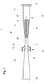
- a fluid stream containing particles or droplets enters the entry tube 2 of separator 1 through inlet port 3.
- the separator shown has an initial section 11 with constant diameter.
- a vortex section 4 comprises a core body 5 extending into the initial section 11 and being surrounded by a structure comprising helical walls 6 forming helical channels filling the space between core body 5 and the inner surface of the wall of entry tube 2.
- the core body has a widening leading end 27 and a tapering trailing end 28.
- the vortex section 4 tapers in the direction of flow through the separator, leading to a rise in the fluid velocity as the fluid passes through the separator.
- the walls are preferably set at an angle in the range 60 - 90 degrees relative to the central axis of the entry tube.
- the distance between the walls, i.e. the width of the helical channels is preferably in the range 50 to 70 mm.
- one or more outlet channels leaving the helical channel in an essentially tangential direction may optionally be provided. These outlet channels remove partial streams in which the concentration of particles has risen due to the centrifugal forces caused by the helical path of the stream.
- the length in the flow direction of the widening upstream end 27 of the core body 5 is preferably at least three times the distance between the helical walls 6.
- the length in the flow direction of the narrowing downstream end 28 of the core body 5 is preferably at least four times the distance between the helical walls 6.
- the described preferred shape of the core body has the effect, that the leading end, widening in the flow direction, directs the incoming flow including particles or droplets, into the helical channel(s) in a laminar manner.
- the trailing end, narrowing in the flow direction stabilizes the flow leaving the helical channel(s) to the periphery of the tube.
- the fluid stream exits the vortex section into a separation section 7, into which the trailing, tapering part of the core body 5 extends.
- the stream is in a vigorous swirling motion, and particles are strongly concentrated at the periphery, i.e. adjacent the wall of the tube.
- the length of the separation section 7 is at least five times the distance between the spiral walls of the vortex section.
- the particle-laden fraction then encounters the exit port section 8, which in the embodiment shown comprises a first flange portion 12 and a second flange portion 13 which are bolted together between respective end flanges (not indicated) of the entry tube 2 and the outlet tube 10.
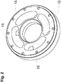
- the structure of flange portion 13 is shown in Fig. 2 .
- the flange parts have four symmetrically arranged exit channels 15 which are set at an angle to receive the swirling flow adjacent the separation section inner wall.
- outlet tube may be of constant diameter or widening in the flow direction.
- the outlet tube has a conical shape widening in the flow direction.
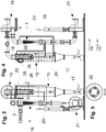
- Fig. 3 and 4 show side sectional views of a separator 1 according to the present invention coupled to a cyclone pre-separator 15.
- Fig. 4 is rotated 90° around a vertical axis relative to Fig. 3 .
- particle-containing fluid here denoted “dusty air”
- the fluid stream is thus set into a spiral downward motion as schematically indicated by the spiral line in Fig. 4 .
- Particles are enriched at the cyclone wall and leave at the bottom at 17.
- the resulting pre-cleaned fluid stream leaves the cyclone in an upward motion through the vertical, central exit tube 18 and is transported to the inlet port 3 of separator 1 by means of primary blower 19. After passing through the separator 1 as set out in connection with Fig. 1 , the cleaned flow is expelled at 20 by means of secondary blower 21.
- the particle-enriched fractions leaving the exit port section of the separator are recycled to the upper part of the cyclone pre-separator via lines 22.
- the recycle lines 22 are arranged symmetrically in the rising tube 25 of the cyclone as shown in Fig. 5 , which represents a view from above at the section A-A indicated in Fig. 3 (only one line 22 is provided with a reference numeral in Fig. 5 ).
- the lines 22 may feed supplemental, clean fluid into the cyclone pre-separator.
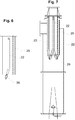
- lines 22 end in nozzles 26 directing the flow towards the inner surface of the cyclone wall, as shown in greater detail in connection with Fig. 6 .
- Figs. 3 and 4 further show a secondary exit port at 24 in the lower part of cyclone pre-separator 15. From this exit port, line 23 conducts a secondary flow directly to the inlet of entry tube 2 of the separator.
- This arrangement lowers the pressure in the cyclone during operation and makes possible the separation of very fine particles.
- a preferable secondary flow is 10 to 20 % of the fluid flow entering the cyclone. This arrangement considerably improves the performance of the cyclone.
- Fig. 6 shows the arrangement of a single recycling line 22 with nozzle 26 fitted to rising tube 25 within the cyclone pre-separator.
- Fig. 7 is a side sectional view of a cyclone pre-separator with four recycle lines 22 and nozzles 26 mounted symmetrically around the cyclone rising tube 25. The nozzles 26 are directed to guide the recycled, particle-enriched flow from the separator exit port section into the downwardly spiraling flow at the cyclone wall.
- control valves may be provided to control e.g. the secondary flow in line 23.
Landscapes
- Chemical & Material Sciences (AREA)
- Chemical Kinetics & Catalysis (AREA)
- Cyclones (AREA)
- Separating Particles In Gases By Inertia (AREA)
- Electrical Discharge Machining, Electrochemical Machining, And Combined Machining (AREA)
Priority Applications (16)
| Application Number | Priority Date | Filing Date | Title |
|---|---|---|---|
| HUE18397532A HUE059649T2 (hu) | 2018-12-12 | 2018-12-12 | Fluidum tisztítására szolgáló készülék és eljárás |
| PT183975325T PT3666362T (pt) | 2018-12-12 | 2018-12-12 | Dispositivo e método para purificação de fluido |
| EP18397532.5A EP3666362B1 (fr) | 2018-12-12 | 2018-12-12 | Dispositif et procédé de purification de fluide |
| ES18397532T ES2925647T3 (es) | 2018-12-12 | 2018-12-12 | Dispositivo y método para la purificación de fluidos |
| DK18397532.5T DK3666362T3 (da) | 2018-12-12 | 2018-12-12 | Indretning og fremgangsmåde til fluidrensning |
| PL18397532.5T PL3666362T3 (pl) | 2018-12-12 | 2018-12-12 | Urządzenie i sposób oczyszczania płynów |
| PCT/FI2019/050883 WO2020120839A1 (fr) | 2018-12-12 | 2019-12-11 | Dispositif et procédé de purification de fluide |
| EP19820819.1A EP3894045B1 (fr) | 2018-12-12 | 2019-12-11 | Dispositif et procédé de purification de fluide |
| ES19820819T ES2971689T3 (es) | 2018-12-12 | 2019-12-11 | Dispositivo y método para la purificación de fluidos |
| US17/413,593 US11786917B2 (en) | 2018-12-12 | 2019-12-11 | Device and method for fluid purification |
| HUE19820819A HUE065685T2 (hu) | 2018-12-12 | 2019-12-11 | Fluidum tisztítására szolgáló készülék és eljárás |
| CA3122549A CA3122549A1 (fr) | 2018-12-12 | 2019-12-11 | Dispositif et procede de purification de fluide |
| AU2019398785A AU2019398785B2 (en) | 2018-12-12 | 2019-12-11 | Device and method for fluid purification |
| HRP20240208TT HRP20240208T1 (hr) | 2018-12-12 | 2019-12-11 | Uređaj i metoda za pročišćavanje tekućine |
| PL19820819.1T PL3894045T3 (pl) | 2018-12-12 | 2019-12-11 | Urządzenie i sposób oczyszczania płynów |
| CN201980082618.8A CN113382796B (zh) | 2018-12-12 | 2019-12-11 | 用于流体净化的装置和方法 |
Applications Claiming Priority (1)
| Application Number | Priority Date | Filing Date | Title |
|---|---|---|---|
| EP18397532.5A EP3666362B1 (fr) | 2018-12-12 | 2018-12-12 | Dispositif et procédé de purification de fluide |
Publications (2)
| Publication Number | Publication Date |
|---|---|
| EP3666362A1 true EP3666362A1 (fr) | 2020-06-17 |
| EP3666362B1 EP3666362B1 (fr) | 2022-06-01 |
Family
ID=64744704
Family Applications (2)
| Application Number | Title | Priority Date | Filing Date |
|---|---|---|---|
| EP18397532.5A Active EP3666362B1 (fr) | 2018-12-12 | 2018-12-12 | Dispositif et procédé de purification de fluide |
| EP19820819.1A Active EP3894045B1 (fr) | 2018-12-12 | 2019-12-11 | Dispositif et procédé de purification de fluide |
Family Applications After (1)
| Application Number | Title | Priority Date | Filing Date |
|---|---|---|---|
| EP19820819.1A Active EP3894045B1 (fr) | 2018-12-12 | 2019-12-11 | Dispositif et procédé de purification de fluide |
Country Status (12)
| Country | Link |
|---|---|
| US (1) | US11786917B2 (fr) |
| EP (2) | EP3666362B1 (fr) |
| CN (1) | CN113382796B (fr) |
| AU (1) | AU2019398785B2 (fr) |
| CA (1) | CA3122549A1 (fr) |
| DK (1) | DK3666362T3 (fr) |
| ES (2) | ES2925647T3 (fr) |
| HR (1) | HRP20240208T1 (fr) |
| HU (2) | HUE059649T2 (fr) |
| PL (2) | PL3666362T3 (fr) |
| PT (1) | PT3666362T (fr) |
| WO (1) | WO2020120839A1 (fr) |
Families Citing this family (2)
| Publication number | Priority date | Publication date | Assignee | Title |
|---|---|---|---|---|
| JP7081034B1 (ja) | 2021-09-22 | 2022-06-06 | リックス株式会社 | 混合液分離装置 |
| JP7081033B1 (ja) | 2021-09-22 | 2022-06-06 | リックス株式会社 | 混合液分離装置 |
Citations (8)
| Publication number | Priority date | Publication date | Assignee | Title |
|---|---|---|---|---|
| DE241042C (fr) * | 1910-07-27 | 1911-11-24 | ||
| US2574370A (en) * | 1948-06-30 | 1951-11-06 | Standard Oil Dev Co | Equipment for removal of entrained solids |
| FR1239547A (fr) * | 1958-10-24 | 1960-08-26 | Perfectionnements apportés aux séparateurs de poussières | |
| EP0344749A2 (fr) | 1988-06-02 | 1989-12-06 | Cyclofil (Proprietary) Limited | Séparateur à tube vortex |
| US5570744A (en) * | 1994-11-28 | 1996-11-05 | Atlantic Richfield Company | Separator systems for well production fluids |
| DE10148405A1 (de) * | 2001-10-01 | 2003-04-10 | Otto Altmann | Doppelwand-Zyklon-System als Abtrennvorrichtung |
| WO2008140307A1 (fr) * | 2007-05-15 | 2008-11-20 | Schinfa Engineering | Procédé de concentration d'organismes microbiologiques en suspension dans un liquide en écoulement |
| DE202012002963U1 (de) * | 2012-03-14 | 2012-04-03 | Raimund Rerucha | Abscheider |
Family Cites Families (40)
| Publication number | Priority date | Publication date | Assignee | Title |
|---|---|---|---|---|
| US2147671A (en) * | 1937-07-15 | 1939-02-21 | Motor Power Inc | Centrifugal gas separator |
| BE568671A (fr) * | 1957-06-21 | |||
| US3577728A (en) * | 1969-03-19 | 1971-05-04 | Joe W Von Brimer | Exhaust gas processing system |
| GB1310792A (en) * | 1970-04-24 | 1973-03-21 | Pall Corp | Vortex separator |
| US3713280A (en) * | 1971-05-17 | 1973-01-30 | Donaldson Co Inc | Ugal air cleaner with static charge dissipating structure19730130 |
| SU587845A3 (ru) | 1974-03-19 | 1978-01-05 | Н.Ф.Недерландсе Газуни (Фирма) | Устройство дл очистки газового потока от твердых и жидких включений |
| US4162906A (en) * | 1977-05-05 | 1979-07-31 | Donaldson Company, Inc. | Side outlet tube |
| US4311494A (en) * | 1977-09-26 | 1982-01-19 | Facet Enterprises, Inc. | Axial flow gas cleaning device |
| DE2918765A1 (de) * | 1979-05-10 | 1980-11-13 | Kloeckner Humboldt Deutz Ag | Fliehkraftstaubabscheidersystem mit mehreren stufen |
| US4272258A (en) * | 1979-11-26 | 1981-06-09 | Shifflett Wiley M | Mud degasser method and apparatus |
| US4389307A (en) * | 1981-06-22 | 1983-06-21 | Queen's University At Kingston | Arrangement of multiple fluid cyclones |
| US4537608A (en) * | 1983-11-16 | 1985-08-27 | Pall Corporation | System for removing contaminant particles from a gas |
| US4629481A (en) * | 1985-01-18 | 1986-12-16 | Westinghouse Electric Corp. | Low pressure drop modular centrifugal moisture separator |
| SU1301459A1 (ru) | 1985-07-10 | 1987-04-07 | Грозненский Нефтяной Институт Им.Акад.М.Д.Миллионщикова | Сепаратор дл очистки газов и паров |
| FR2632215B1 (fr) * | 1988-06-02 | 1992-07-03 | Cyclofil Pty Ltd | Dispositif de separation a tube a tourbillon |
| US4859347A (en) * | 1988-11-18 | 1989-08-22 | Simon Wayne E | Centrifugal separator |
| ZA931264B (en) * | 1992-02-27 | 1993-09-17 | Atomic Energy South Africa | Filtration. |
| CA2155131C (fr) | 1993-04-27 | 2001-06-12 | Jean S. Weingarten | Separateur gaz-liquide de fond de puits |
| US5531811A (en) * | 1994-08-16 | 1996-07-02 | Marathon Oil Company | Method for recovering entrained liquid from natural gas |
| US5902378A (en) * | 1997-07-16 | 1999-05-11 | Obrejanu; Marcel | Continuous flow downhole gas separator for processing cavity pumps |
| US6669843B2 (en) * | 2001-06-12 | 2003-12-30 | Hydrotreat, Inc. | Apparatus for mixing fluids |
| MY134342A (en) | 2001-12-31 | 2007-12-31 | Shell Int Research | Multistage fluid separation assembly and method |
| WO2004020074A1 (fr) * | 2002-09-02 | 2004-03-11 | Shell Internationale Research Maatschappij B.V. | Separateur cyclonique de fluide |
| EP1729621B1 (fr) * | 2004-03-24 | 2013-03-20 | Donaldson Company, Inc. | Cartouche de filtration d'air et procede de fabrication |
| EP1782870A1 (fr) * | 2005-10-28 | 2007-05-09 | M-I Epcon As | Dispositif de séparation |
| EP2415507A1 (fr) * | 2006-09-26 | 2012-02-08 | Dresser-Rand Company | Dispositif de séparation de fluides statique amélioré |
| EP1974790A1 (fr) | 2007-03-26 | 2008-10-01 | Twister B.V. | Séparateur de fluide de cyclone |
| US7934606B2 (en) * | 2007-05-24 | 2011-05-03 | Advanced Petroleum Technologies, Inc. | Induced vortex particle separator |
| US7879123B2 (en) * | 2007-09-27 | 2011-02-01 | Pall Corporation | Inertial separator |
| US7931719B2 (en) * | 2007-12-03 | 2011-04-26 | National Tank Company | Revolution vortex tube gas/liquids separator |
| CN101910601B (zh) * | 2008-02-14 | 2013-11-06 | 唐纳森公司 | 雨帽预滤清器,具有雨帽预滤清器的机动车辆,和预清洁空气的方法 |
| CN101530708A (zh) * | 2009-03-13 | 2009-09-16 | 张兆奇 | 一种废气的净化方法及设备 |
| CN101898175A (zh) * | 2010-01-29 | 2010-12-01 | 北京石油化工学院 | 壁面开槽的旋风分离器 |
| US8425641B2 (en) * | 2010-06-30 | 2013-04-23 | General Electric Company | Inlet air filtration system |
| SE536286C2 (sv) * | 2011-10-06 | 2013-07-30 | Husqvarna Ab | Stoftavskiljare med konstant sugkraft |
| DK177710B1 (en) * | 2012-09-14 | 2014-03-31 | Alfa Laval Corp Ab | Auger conveyor for a centrifugal separator, in particular a decanter centrifuge, and a centrifugal separator |
| WO2016025056A2 (fr) * | 2014-05-29 | 2016-02-18 | General Electric Company | Moteur de turbine, et épurateurs de particules pour celui-ci |
| NO341179B1 (en) * | 2015-08-28 | 2017-09-04 | Fjords Proc As | Axial flow demister |
| US10661210B2 (en) * | 2015-09-15 | 2020-05-26 | Miniature Precision Components, Inc. | Oil separator including spiral members defining helical flow paths |
| US10704425B2 (en) * | 2016-07-14 | 2020-07-07 | General Electric Company | Assembly for a gas turbine engine |
-
2018
- 2018-12-12 HU HUE18397532A patent/HUE059649T2/hu unknown
- 2018-12-12 DK DK18397532.5T patent/DK3666362T3/da active
- 2018-12-12 PT PT183975325T patent/PT3666362T/pt unknown
- 2018-12-12 ES ES18397532T patent/ES2925647T3/es active Active
- 2018-12-12 PL PL18397532.5T patent/PL3666362T3/pl unknown
- 2018-12-12 EP EP18397532.5A patent/EP3666362B1/fr active Active
-
2019
- 2019-12-11 US US17/413,593 patent/US11786917B2/en active Active
- 2019-12-11 CN CN201980082618.8A patent/CN113382796B/zh active Active
- 2019-12-11 ES ES19820819T patent/ES2971689T3/es active Active
- 2019-12-11 HU HUE19820819A patent/HUE065685T2/hu unknown
- 2019-12-11 CA CA3122549A patent/CA3122549A1/fr active Pending
- 2019-12-11 WO PCT/FI2019/050883 patent/WO2020120839A1/fr not_active Ceased
- 2019-12-11 AU AU2019398785A patent/AU2019398785B2/en active Active
- 2019-12-11 PL PL19820819.1T patent/PL3894045T3/pl unknown
- 2019-12-11 HR HRP20240208TT patent/HRP20240208T1/hr unknown
- 2019-12-11 EP EP19820819.1A patent/EP3894045B1/fr active Active
Patent Citations (8)
| Publication number | Priority date | Publication date | Assignee | Title |
|---|---|---|---|---|
| DE241042C (fr) * | 1910-07-27 | 1911-11-24 | ||
| US2574370A (en) * | 1948-06-30 | 1951-11-06 | Standard Oil Dev Co | Equipment for removal of entrained solids |
| FR1239547A (fr) * | 1958-10-24 | 1960-08-26 | Perfectionnements apportés aux séparateurs de poussières | |
| EP0344749A2 (fr) | 1988-06-02 | 1989-12-06 | Cyclofil (Proprietary) Limited | Séparateur à tube vortex |
| US5570744A (en) * | 1994-11-28 | 1996-11-05 | Atlantic Richfield Company | Separator systems for well production fluids |
| DE10148405A1 (de) * | 2001-10-01 | 2003-04-10 | Otto Altmann | Doppelwand-Zyklon-System als Abtrennvorrichtung |
| WO2008140307A1 (fr) * | 2007-05-15 | 2008-11-20 | Schinfa Engineering | Procédé de concentration d'organismes microbiologiques en suspension dans un liquide en écoulement |
| DE202012002963U1 (de) * | 2012-03-14 | 2012-04-03 | Raimund Rerucha | Abscheider |
Also Published As
| Publication number | Publication date |
|---|---|
| EP3666362B1 (fr) | 2022-06-01 |
| PT3666362T (pt) | 2022-09-01 |
| HUE059649T2 (hu) | 2022-12-28 |
| EP3894045A1 (fr) | 2021-10-20 |
| ES2971689T3 (es) | 2024-06-06 |
| WO2020120839A1 (fr) | 2020-06-18 |
| CN113382796A (zh) | 2021-09-10 |
| EP3894045C0 (fr) | 2024-01-17 |
| US11786917B2 (en) | 2023-10-17 |
| AU2019398785A1 (en) | 2021-07-29 |
| ES2925647T3 (es) | 2022-10-19 |
| HUE065685T2 (hu) | 2024-06-28 |
| CN113382796B (zh) | 2023-09-22 |
| US20220032325A1 (en) | 2022-02-03 |
| PL3666362T3 (pl) | 2022-11-21 |
| PL3894045T3 (pl) | 2024-05-06 |
| CA3122549A1 (fr) | 2020-06-18 |
| DK3666362T3 (da) | 2022-08-29 |
| HRP20240208T1 (hr) | 2024-04-26 |
| EP3894045B1 (fr) | 2024-01-17 |
| AU2019398785B2 (en) | 2025-04-17 |
Similar Documents
| Publication | Publication Date | Title |
|---|---|---|
| EP2882536B1 (fr) | Appareil destiné à la séparation cyclonique d'un écoulement liquide dans une phase gazeuse et une phase liquide et réservoir pourvu d'un tel appareil | |
| CN103648656B (zh) | 用于旋流分离器的流动偏转元件 | |
| US3925045A (en) | Multistage cyclonic separator | |
| CA1197478A (fr) | Cyclones separateurs | |
| EP0105273A1 (fr) | Ameliorations relatives a des separateurs cycloniques. | |
| EP3894045B1 (fr) | Dispositif et procédé de purification de fluide | |
| RU2664985C1 (ru) | Способ очистки воздушно-пылевого потока и устройство для его очистки | |
| US3169842A (en) | Cyclones for removing solids from gas | |
| CZ285066B6 (cs) | Způsob a zařízení k oddělování alespoň jedné látky z kapalného nebo plynného média | |
| CN114729508B (zh) | 带有清洁器稀释装置的浆料清洁器系统及用该系统清洁浆料的方法 | |
| US2806550A (en) | Dust separators or concentrators of the cyclone type | |
| US5215553A (en) | Apparatus for separating particles from a gaseous medium | |
| RU2803224C2 (ru) | Устройство и способ для очистки текучей среды | |
| GB2108013A (en) | Improvements in or relating to cyclone separators | |
| CN117642538A (zh) | 从悬浮液中离心分离固体的水力旋流器装置 | |
| CN109843445A (zh) | 旋液分离器 | |
| EP0745417B1 (fr) | Installation pour la séparation des particules solides d'un courant de gaz | |
| CA1161374A (fr) | Methode et dispositif pour separer les particules des gaz qui les charrient | |
| RU2316397C1 (ru) | Пылеуловитель мелкодисперсной пыли | |
| SU660695A1 (ru) | Центробежный аппарат дл очистки газа от взвешенных частиц | |
| RU2206408C1 (ru) | Гидроциклон | |
| SU850221A1 (ru) | Устройство дл отделени пыли | |
| RU2323767C2 (ru) | Вихрединамический сепаратор | |
| SU980851A1 (ru) | Гидроциклон | |
| FI80836C (fi) | Tvaotas eller flertas cyklonavskiljare eller sorterare. |
Legal Events
| Date | Code | Title | Description |
|---|---|---|---|
| PUAI | Public reference made under article 153(3) epc to a published international application that has entered the european phase |
Free format text: ORIGINAL CODE: 0009012 |
|
| STAA | Information on the status of an ep patent application or granted ep patent |
Free format text: STATUS: THE APPLICATION HAS BEEN PUBLISHED |
|
| AK | Designated contracting states |
Kind code of ref document: A1 Designated state(s): AL AT BE BG CH CY CZ DE DK EE ES FI FR GB GR HR HU IE IS IT LI LT LU LV MC MK MT NL NO PL PT RO RS SE SI SK SM TR |
|
| AX | Request for extension of the european patent |
Extension state: BA ME |
|
| STAA | Information on the status of an ep patent application or granted ep patent |
Free format text: STATUS: REQUEST FOR EXAMINATION WAS MADE |
|
| 17P | Request for examination filed |
Effective date: 20201210 |
|
| RBV | Designated contracting states (corrected) |
Designated state(s): AL AT BE BG CH CY CZ DE DK EE ES FI FR GB GR HR HU IE IS IT LI LT LU LV MC MK MT NL NO PL PT RO RS SE SI SK SM TR |
|
| STAA | Information on the status of an ep patent application or granted ep patent |
Free format text: STATUS: EXAMINATION IS IN PROGRESS |
|
| 17Q | First examination report despatched |
Effective date: 20210122 |
|
| GRAP | Despatch of communication of intention to grant a patent |
Free format text: ORIGINAL CODE: EPIDOSNIGR1 |
|
| STAA | Information on the status of an ep patent application or granted ep patent |
Free format text: STATUS: GRANT OF PATENT IS INTENDED |
|
| INTG | Intention to grant announced |
Effective date: 20211207 |
|
| GRAS | Grant fee paid |
Free format text: ORIGINAL CODE: EPIDOSNIGR3 |
|
| GRAA | (expected) grant |
Free format text: ORIGINAL CODE: 0009210 |
|
| STAA | Information on the status of an ep patent application or granted ep patent |
Free format text: STATUS: THE PATENT HAS BEEN GRANTED |
|
| RAP3 | Party data changed (applicant data changed or rights of an application transferred) |
Owner name: FILTRA GROUP OY |
|
| RIN1 | Information on inventor provided before grant (corrected) |
Inventor name: HEKKALA, LAURI Inventor name: VALLI, VEIKKO |
|
| AK | Designated contracting states |
Kind code of ref document: B1 Designated state(s): AL AT BE BG CH CY CZ DE DK EE ES FI FR GB GR HR HU IE IS IT LI LT LU LV MC MK MT NL NO PL PT RO RS SE SI SK SM TR |
|
| REG | Reference to a national code |
Ref country code: GB Ref legal event code: FG4D |
|
| REG | Reference to a national code |
Ref country code: AT Ref legal event code: REF Ref document number: 1494984 Country of ref document: AT Kind code of ref document: T Effective date: 20220615 Ref country code: CH Ref legal event code: EP |
|
| REG | Reference to a national code |
Ref country code: IE Ref legal event code: FG4D |
|
| REG | Reference to a national code |
Ref country code: DE Ref legal event code: R096 Ref document number: 602018036154 Country of ref document: DE |
|
| REG | Reference to a national code |
Ref country code: FI Ref legal event code: FGE Ref country code: DK Ref legal event code: T3 Effective date: 20220822 |
|
| REG | Reference to a national code |
Ref country code: RO Ref legal event code: EPE |
|
| REG | Reference to a national code |
Ref country code: CH Ref legal event code: PK Free format text: BERICHTIGUNGEN |
|
| REG | Reference to a national code |
Ref country code: PT Ref legal event code: SC4A Ref document number: 3666362 Country of ref document: PT Date of ref document: 20220901 Kind code of ref document: T Free format text: AVAILABILITY OF NATIONAL TRANSLATION Effective date: 20220826 |
|
| REG | Reference to a national code |
Ref country code: NL Ref legal event code: FP |
|
| REG | Reference to a national code |
Ref country code: SE Ref legal event code: TRGR |
|
| RAP4 | Party data changed (patent owner data changed or rights of a patent transferred) |
Owner name: FILTRA GROUP OY |
|
| RIN2 | Information on inventor provided after grant (corrected) |
Inventor name: HEKKALA, LAURI Inventor name: VALLI, VEIKKO |
|
| REG | Reference to a national code |
Ref country code: LT Ref legal event code: MG9D |
|
| REG | Reference to a national code |
Ref country code: NO Ref legal event code: T2 Effective date: 20220601 |
|
| REG | Reference to a national code |
Ref country code: ES Ref legal event code: FG2A Ref document number: 2925647 Country of ref document: ES Kind code of ref document: T3 Effective date: 20221019 |
|
| PG25 | Lapsed in a contracting state [announced via postgrant information from national office to epo] |
Ref country code: LT Free format text: LAPSE BECAUSE OF FAILURE TO SUBMIT A TRANSLATION OF THE DESCRIPTION OR TO PAY THE FEE WITHIN THE PRESCRIBED TIME-LIMIT Effective date: 20220601 Ref country code: HR Free format text: LAPSE BECAUSE OF FAILURE TO SUBMIT A TRANSLATION OF THE DESCRIPTION OR TO PAY THE FEE WITHIN THE PRESCRIBED TIME-LIMIT Effective date: 20220601 Ref country code: GR Free format text: LAPSE BECAUSE OF FAILURE TO SUBMIT A TRANSLATION OF THE DESCRIPTION OR TO PAY THE FEE WITHIN THE PRESCRIBED TIME-LIMIT Effective date: 20220902 Ref country code: BG Free format text: LAPSE BECAUSE OF FAILURE TO SUBMIT A TRANSLATION OF THE DESCRIPTION OR TO PAY THE FEE WITHIN THE PRESCRIBED TIME-LIMIT Effective date: 20220901 |
|
| REG | Reference to a national code |
Ref country code: SK Ref legal event code: T3 Ref document number: E 40498 Country of ref document: SK |
|
| PG25 | Lapsed in a contracting state [announced via postgrant information from national office to epo] |
Ref country code: RS Free format text: LAPSE BECAUSE OF FAILURE TO SUBMIT A TRANSLATION OF THE DESCRIPTION OR TO PAY THE FEE WITHIN THE PRESCRIBED TIME-LIMIT Effective date: 20220601 Ref country code: LV Free format text: LAPSE BECAUSE OF FAILURE TO SUBMIT A TRANSLATION OF THE DESCRIPTION OR TO PAY THE FEE WITHIN THE PRESCRIBED TIME-LIMIT Effective date: 20220601 |
|
| REG | Reference to a national code |
Ref country code: HU Ref legal event code: AG4A Ref document number: E059649 Country of ref document: HU |
|
| PG25 | Lapsed in a contracting state [announced via postgrant information from national office to epo] |
Ref country code: SM Free format text: LAPSE BECAUSE OF FAILURE TO SUBMIT A TRANSLATION OF THE DESCRIPTION OR TO PAY THE FEE WITHIN THE PRESCRIBED TIME-LIMIT Effective date: 20220601 Ref country code: EE Free format text: LAPSE BECAUSE OF FAILURE TO SUBMIT A TRANSLATION OF THE DESCRIPTION OR TO PAY THE FEE WITHIN THE PRESCRIBED TIME-LIMIT Effective date: 20220601 |
|
| PG25 | Lapsed in a contracting state [announced via postgrant information from national office to epo] |
Ref country code: IS Free format text: LAPSE BECAUSE OF FAILURE TO SUBMIT A TRANSLATION OF THE DESCRIPTION OR TO PAY THE FEE WITHIN THE PRESCRIBED TIME-LIMIT Effective date: 20221001 |
|
| REG | Reference to a national code |
Ref country code: DE Ref legal event code: R097 Ref document number: 602018036154 Country of ref document: DE |
|
| PG25 | Lapsed in a contracting state [announced via postgrant information from national office to epo] |
Ref country code: AL Free format text: LAPSE BECAUSE OF FAILURE TO SUBMIT A TRANSLATION OF THE DESCRIPTION OR TO PAY THE FEE WITHIN THE PRESCRIBED TIME-LIMIT Effective date: 20220601 |
|
| PLBE | No opposition filed within time limit |
Free format text: ORIGINAL CODE: 0009261 |
|
| STAA | Information on the status of an ep patent application or granted ep patent |
Free format text: STATUS: NO OPPOSITION FILED WITHIN TIME LIMIT |
|
| 26N | No opposition filed |
Effective date: 20230302 |
|
| PG25 | Lapsed in a contracting state [announced via postgrant information from national office to epo] |
Ref country code: SI Free format text: LAPSE BECAUSE OF FAILURE TO SUBMIT A TRANSLATION OF THE DESCRIPTION OR TO PAY THE FEE WITHIN THE PRESCRIBED TIME-LIMIT Effective date: 20220601 |
|
| P01 | Opt-out of the competence of the unified patent court (upc) registered |
Effective date: 20230502 |
|
| PG25 | Lapsed in a contracting state [announced via postgrant information from national office to epo] |
Ref country code: RO Free format text: LAPSE BECAUSE OF NON-PAYMENT OF DUE FEES Effective date: 20220601 |
|
| PG25 | Lapsed in a contracting state [announced via postgrant information from national office to epo] |
Ref country code: LU Free format text: LAPSE BECAUSE OF NON-PAYMENT OF DUE FEES Effective date: 20221212 |
|
| PG25 | Lapsed in a contracting state [announced via postgrant information from national office to epo] |
Ref country code: IE Free format text: LAPSE BECAUSE OF NON-PAYMENT OF DUE FEES Effective date: 20221212 |
|
| PG25 | Lapsed in a contracting state [announced via postgrant information from national office to epo] |
Ref country code: CY Free format text: LAPSE BECAUSE OF FAILURE TO SUBMIT A TRANSLATION OF THE DESCRIPTION OR TO PAY THE FEE WITHIN THE PRESCRIBED TIME-LIMIT Effective date: 20220601 |
|
| PG25 | Lapsed in a contracting state [announced via postgrant information from national office to epo] |
Ref country code: MK Free format text: LAPSE BECAUSE OF FAILURE TO SUBMIT A TRANSLATION OF THE DESCRIPTION OR TO PAY THE FEE WITHIN THE PRESCRIBED TIME-LIMIT Effective date: 20220601 |
|
| PG25 | Lapsed in a contracting state [announced via postgrant information from national office to epo] |
Ref country code: MC Free format text: LAPSE BECAUSE OF FAILURE TO SUBMIT A TRANSLATION OF THE DESCRIPTION OR TO PAY THE FEE WITHIN THE PRESCRIBED TIME-LIMIT Effective date: 20220601 |
|
| PG25 | Lapsed in a contracting state [announced via postgrant information from national office to epo] |
Ref country code: MC Free format text: LAPSE BECAUSE OF FAILURE TO SUBMIT A TRANSLATION OF THE DESCRIPTION OR TO PAY THE FEE WITHIN THE PRESCRIBED TIME-LIMIT Effective date: 20220601 |
|
| PG25 | Lapsed in a contracting state [announced via postgrant information from national office to epo] |
Ref country code: MT Free format text: LAPSE BECAUSE OF FAILURE TO SUBMIT A TRANSLATION OF THE DESCRIPTION OR TO PAY THE FEE WITHIN THE PRESCRIBED TIME-LIMIT Effective date: 20220601 |
|
| PG25 | Lapsed in a contracting state [announced via postgrant information from national office to epo] |
Ref country code: BG Free format text: LAPSE BECAUSE OF FAILURE TO SUBMIT A TRANSLATION OF THE DESCRIPTION OR TO PAY THE FEE WITHIN THE PRESCRIBED TIME-LIMIT Effective date: 20220601 |
|
| PG25 | Lapsed in a contracting state [announced via postgrant information from national office to epo] |
Ref country code: BG Free format text: LAPSE BECAUSE OF FAILURE TO SUBMIT A TRANSLATION OF THE DESCRIPTION OR TO PAY THE FEE WITHIN THE PRESCRIBED TIME-LIMIT Effective date: 20220601 |
|
| PGFP | Annual fee paid to national office [announced via postgrant information from national office to epo] |
Ref country code: PT Payment date: 20251204 Year of fee payment: 8 |
|
| REG | Reference to a national code |
Ref country code: CH Ref legal event code: U11 Free format text: ST27 STATUS EVENT CODE: U-0-0-U10-U11 (AS PROVIDED BY THE NATIONAL OFFICE) Effective date: 20260101 |
|
| PGFP | Annual fee paid to national office [announced via postgrant information from national office to epo] |
Ref country code: DE Payment date: 20251211 Year of fee payment: 8 |
|
| PGFP | Annual fee paid to national office [announced via postgrant information from national office to epo] |
Ref country code: GB Payment date: 20251219 Year of fee payment: 8 |
|
| PGFP | Annual fee paid to national office [announced via postgrant information from national office to epo] |
Ref country code: AT Payment date: 20251222 Year of fee payment: 8 |
|
| PGFP | Annual fee paid to national office [announced via postgrant information from national office to epo] |
Ref country code: IT Payment date: 20251223 Year of fee payment: 8 Ref country code: FI Payment date: 20251208 Year of fee payment: 8 Ref country code: DK Payment date: 20251224 Year of fee payment: 8 |
|
| PGFP | Annual fee paid to national office [announced via postgrant information from national office to epo] |
Ref country code: HU Payment date: 20251223 Year of fee payment: 8 Ref country code: NL Payment date: 20251219 Year of fee payment: 8 Ref country code: FR Payment date: 20251229 Year of fee payment: 8 |
|
| PGFP | Annual fee paid to national office [announced via postgrant information from national office to epo] |
Ref country code: TR Payment date: 20251208 Year of fee payment: 8 Ref country code: BE Payment date: 20251219 Year of fee payment: 8 |
|
| PGFP | Annual fee paid to national office [announced via postgrant information from national office to epo] |
Ref country code: SE Payment date: 20251219 Year of fee payment: 8 |
|
| PGFP | Annual fee paid to national office [announced via postgrant information from national office to epo] |
Ref country code: CZ Payment date: 20251209 Year of fee payment: 8 |
|
| PGFP | Annual fee paid to national office [announced via postgrant information from national office to epo] |
Ref country code: PL Payment date: 20251205 Year of fee payment: 8 |
|
| PGFP | Annual fee paid to national office [announced via postgrant information from national office to epo] |
Ref country code: SK Payment date: 20251210 Year of fee payment: 8 Ref country code: RO Payment date: 20251209 Year of fee payment: 8 |
|
| PGFP | Annual fee paid to national office [announced via postgrant information from national office to epo] |
Ref country code: ES Payment date: 20260130 Year of fee payment: 8 |
|
| PGFP | Annual fee paid to national office [announced via postgrant information from national office to epo] |
Ref country code: NO Payment date: 20251230 Year of fee payment: 8 |
|
| PGFP | Annual fee paid to national office [announced via postgrant information from national office to epo] |
Ref country code: CH Payment date: 20260101 Year of fee payment: 8 |