EP3666432A1 - Vorrichtung zur festen verbindung einer bohrvorrichtung mit einem bohrgitter, das einen kugelspannsatz umfasst - Google Patents
Vorrichtung zur festen verbindung einer bohrvorrichtung mit einem bohrgitter, das einen kugelspannsatz umfasst Download PDFInfo
- Publication number
- EP3666432A1 EP3666432A1 EP19212196.0A EP19212196A EP3666432A1 EP 3666432 A1 EP3666432 A1 EP 3666432A1 EP 19212196 A EP19212196 A EP 19212196A EP 3666432 A1 EP3666432 A1 EP 3666432A1
- Authority
- EP
- European Patent Office
- Prior art keywords
- drilling
- grid
- expansion cone
- ring
- locking
- Prior art date
- Legal status (The legal status is an assumption and is not a legal conclusion. Google has not performed a legal analysis and makes no representation as to the accuracy of the status listed.)
- Granted
Links
Images


Classifications
-
- B—PERFORMING OPERATIONS; TRANSPORTING
- B23—MACHINE TOOLS; METAL-WORKING NOT OTHERWISE PROVIDED FOR
- B23B—TURNING; BORING
- B23B49/00—Measuring or gauging equipment on boring machines for positioning or guiding the drill; Devices for indicating failure of drills during boring; Centering devices for holes to be bored
- B23B49/02—Boring templates or bushings
- B23B49/023—Bushings and their connection to the template
-
- B—PERFORMING OPERATIONS; TRANSPORTING
- B23—MACHINE TOOLS; METAL-WORKING NOT OTHERWISE PROVIDED FOR
- B23B—TURNING; BORING
- B23B2215/00—Details of workpieces
- B23B2215/04—Aircraft components
-
- B—PERFORMING OPERATIONS; TRANSPORTING
- B23—MACHINE TOOLS; METAL-WORKING NOT OTHERWISE PROVIDED FOR
- B23B—TURNING; BORING
- B23B41/00—Boring or drilling machines or devices specially adapted for particular work; Accessories specially adapted therefor
-
- B—PERFORMING OPERATIONS; TRANSPORTING
- B23—MACHINE TOOLS; METAL-WORKING NOT OTHERWISE PROVIDED FOR
- B23B—TURNING; BORING
- B23B49/00—Measuring or gauging equipment on boring machines for positioning or guiding the drill; Devices for indicating failure of drills during boring; Centering devices for holes to be bored
- B23B49/02—Boring templates or bushings
Definitions
- the field of the invention is that of the design and manufacture of the fastening devices used to fasten drilling devices to drilling grids.
- the locations of the holes to be made are generally defined by means of drilling grids.
- a drilling grid is in the form of a plate traversed by a plurality of positioning bores.
- Such a grid is intended to be fixedly placed near an element to be drilled, this in a particular predetermined position so that the position of the positioning bores corresponds to locations where holes must be drilled in the element to be drilled. drill.
- a drilling device is fixed to one of the positioning bores and a hole is made in the element to be drilled.
- the drilling device is then secured to another bore of the grid to make another hole in the element to be drilled.
- the drilling device is thus successively secured to different bores for positioning the grid so as to make a plurality of holes in the element to be drilled.
- the drilling devices generally used are automatic advance drilling devices (comprising a single motor for driving a drilling spindle in translation and in rotation along the same axis) or drilling devices with controlled cutting parameters (comprising a feed motor and a rotation motor to drive a drilling spindle in translation and in rotation along the same axis).
- the fastening of a piercing device to the grid is carried out by means of a fastening device comprising an expandable hub.
- the displacement in translation of the expansion cone with respect to the expandable ring is obtained by a jack, generally pneumatic.
- This cylinder is arranged perpendicular to the expansion cone and for driving it via a movement transformation device such as rollers rolling in a slide inclined relative to the axes of the cone and of the cylinder or a spreader.
- the axial force applied to the expansion cone generates a contact pressure between the expandable hub and the positioning bore in which it is housed in the locked position.
- This contact pressure and the associated friction must be sufficient to oppose the reaction torque and the thrust forces along the drilling axis transmitted to the drill during a drilling operation and guarantee that the drilling device is correctly secured to the grid. The reliability of this connection is therefore dependent on the axial force generated by the jack.
- the piercing device can slide relative to the grid during a piercing operation. Such sliding can have repercussions on the quality of the drilling, in particular on its depth if the device drilling moves back with respect to the grid during a drilling operation. This is not acceptable since the geometric tolerances imposed in the aeronautical sector are often low.
- the risk of the drilling device sliding relative to the grid during a drilling operation is all the greater the harder the material to be drilled, the more the cutting tool is worn (in these two cases, the more thrust and the torque transmitted to the drill during drilling) and that the drilling is carried out with lubrication.
- Another solution to avoid the sliding of the piercing device relative to the piercing grid is to implement additional mechanical restraint systems comprising a bayonet system 1 ⁇ 4 turn integral with the piercing device provided to cooperate with shouldered screws integral with the drilling grid.
- Such a system has the disadvantage of being bulky and not being compatible with a tight grid spacing.
- the invention particularly aims to provide an effective solution to at least some of these different problems.
- an objective of the invention is to provide a device for securing a drilling device to a drilling grid which makes it possible to make holes with small geometric tolerances.
- the invention aims, according to at least one embodiment, to provide such a securing device which ensures good repeatability over the depth of a plurality of holes.
- Another objective of the invention is to providing such a securing device which makes it possible to prevent the piercing device from slipping, in particular backward, with respect to the piercing grid during a piercing operation.
- the invention aims, according to at least one embodiment, to provide such a fastening device which is compact.
- Another object of the invention is, according to at least one embodiment, to provide such a fastening device which requires the deployment of relatively reduced forces to ensure that an effective drilling device is maintained in position relative to a drilling grid during a drilling operation.
- Another objective of the invention is, according to at least one embodiment, to provide such a fastening device which is compact and / or simple in design and / or robust.
- the invention consists in implementing an expandable ball hub to ensure the attachment of a drilling device to a drilling grid.
- balls which are housed in a peripheral housing integral with a positioning bore of a drilling grid makes it possible to simply but effectively block in translation the drilling device relative to the grid.
- the drilling device can not move in translation along the drilling axis relative to the drilling grid, in particular it can not move back. This guarantees compliance with the low geometric tolerances which are generally imposed, and in particular the repeatability of the depth of successive drillings.
- the technique according to the invention thus makes it possible, by implementing a compact and simple solution, to produce quality bores.
- said balls are housed in longitudinal grooves formed on the surface of said expansion cone.
- each of said grooves comprises a first stage and a second stage separated by an inclined ramp, the bottom of said first stage being closer to the longitudinal axis of said expansion cone than the bottom, said balls being located against said first stage in said unlocking position and against said second stage in said locking position.
- said grooves are not through.
- said positioning bores are formed in said drilling grid.
- a securing device comprises guide rings intended to be secured to said drilling grid and traversed by said positioning bore.
- peripheral blocking housings are formed in said grid or in said guide rings.
- said body comprises a stop intended to come into abutment against a surface of said drilling grid or against a surface of said guide rings oriented towards said fastening device.
- said guide ring comprises a shoulder of complementary shape of a housing formed in said bores for positioning of said grid.
- said shoulder is preferably formed on the side of said grid opposite to that oriented towards said securing device.
- the passage of said cone from its release position to its locking position takes place in the direction of the surface of said piercing grid oriented towards said securing device, or vice versa.
- said means for driving in translation of said expansion cone comprise a jack, said jack comprising a cylinder arranged inside said body and a piston mounted movable in translation inside said cylinder along the axis. for translating said expansion cone, said expansion cone being integral in translation with said piston.
- said cylinder is double-acting.
- said cylinder of said cylinder comprises a locking chamber placed on one side of the piston and intended to be supplied with power to move said expansion cone in its locked position and a release chamber placed on the other side of the piston and intended to be powered to move said expansion cone in its release position, the surface of the face of the piston located in said unlocking chamber being greater than the surface of the face of said piston located in said locking chamber.
- a device comprises means for regulating said means for driving in translation of said expansion cone, said regulating means being configured so that the speed of movement in translation printed on said expansion cone by said drive means is greater during its passage from said release position to said locking position than during its passage from said locking position to said release position.
- a fastening device according to the invention is traversed right through by a drilling barrel.
- Such a fastening device can be implemented to ensure the fastening of any type of drilling device (or drill) to a drilling grid which ranks including, but not limited to, drills with controlled torque parameters and drills with automatic advance.
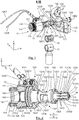
- such a fastening device 1 comprises a body 10 comprising at a first end of the first fastening means 11 to a drilling device, and at its opposite end of the second fastening means 12 to a drilling grid 13.
- a drilling grid 13 conventionally comprises a plate 130 traversed by a plurality of positioning bores 131.
- a plate 130 can be flat, curved or have any other shape suitable for drilling the element to be drilled . It has a surface 132 oriented on the side of the piercing device, that is to say on the side of the securing device, and an opposite surface 133 oriented on the side of an element to be drilled.
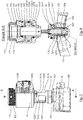
- the first means 11 for securing the device to a drill include a knurled nut 110 capable of being screwed onto a threaded portion 113 of the body 10 or more precisely of a plug 14 which will be described in more detail below.
- the nut 110 can be tightened by means of a hook wrench which is housed in the holes 111.
- the knurled nut 110 has a shoulder 114.
- the second means 12 for securing the device to a drilling grid comprise an expandable ball hub which will be described in more detail below.
- the body 10 comprises a first portion 100 of large diameter extended by a second portion 101 of smaller diameter.
- the first portion 100 is traversed by a bore 1220.
- This bore 1220 is open to the outside at its anterior end and closed by means of a plug 14 screwed into the body 10.
- the plug 14 carries an O-ring 140 to ensure a hermetic closure of the bore 1220.
- the plug 14 is capable of housing an inner ring 141 which is held there between a shoulder 142 formed inside the plug 14 and a shoulder 114 of the knurled nut 110.
- This inner ring 141 is designed to be secured to the end of the drilling device to be joined to the joining device.
- the second portion 101 is crossed laterally by slots 1010 which allow the evacuation of the chips during a drilling operation.
- the rear end of the second portion 101 has a threaded portion 1011 on which is screwed a nut 15 with transverse holes 150 to allow the introduction of a lug wrench to ensure the tightening of the nut 15 on the body 10.
- the nut 15 comprises a stop 151 defining a bearing surface intended to come into abutment against the surface 132 of the grid 13 oriented towards the securing device when the latter is secured to the grid 13.
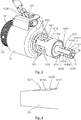
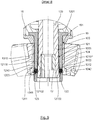
- the expandable ring 120 comprises a portion 1200 with an essentially cylindrical outer contour extended at one of its ends by a shoulder 1201 having a flat (not shown).
- This shoulder 1201 is housed inside a bore 1012 formed at the rear end of the second portion 101 of the body and having a flat 1013 of shape complementary to the flat of the expandable ring 120.
- the expandable ring 120 is secured to the body 10 by means of the nut 15 which locks it in translation with respect to the body 10.
- the expandable ring 120 is locked in rotation with respect to the body 10 by the flats.
- Longitudinal slots 1204 are formed longitudinally at the periphery of the portion 1200 of the expandable ring 120 so as to allow the expandable ring to expand and to retract as will emerge more clearly later.
- the expandable ring 120 is crossed by a conical bore 1202 (or more exactly frustoconical) formed along a longitudinal axis of the expandable ring.
- the angle of the bore 1202 is such that the conical bore 1202 has a small diameter end on the side of the body 10 and a larger diameter end opposite.
- the rear end of the expandable ring 120 is crossed by radial orifices 1203 formed along axes perpendicular to the longitudinal axis of the expandable ring 120 and distributed uniformly around this longitudinal axis.
- the conical bore 1202 of the expandable ring 120 houses the expansion cone 121.
- the expansion cone 121 has an outer peripheral contour of shape complementary to the inner peripheral contour of the conical bore 1202.
- the expansion cone 121 is mounted movable in translation inside the conical bore 1202 along the longitudinal axis thereof.
- Longitudinal grooves 1210 are formed on the surface of the expansion cone 121.
- these grooves 1210 are stepped. They each include a first stage 12100 and a second stage 12101 separated by an inclined ramp 12102. The bottom of each stage extends essentially parallel to the longitudinal axis of the expansion cone 121. The bottom of the first stage 12100 is closer from the longitudinal axis of the expansion cone as the bottom of the second stage 12101.
- the grooves 1210 are preferably non-emerging, that is to say that they are not open to the outside at the rear end of the expansion cone 121.
- Each groove 1210 houses a locking ball 123.
- each orifice 1203 is slightly tightened to prevent the ball 123 which is housed therein from coming out completely .
- the outside diameter of each orifice 1203 can for example have a work hardening 1205 forming a projection inside the orifice as shown in FIG. figure 11 .
- Another solution could of course be implemented. This diameter is chosen so that the ball 123 which is housed therein forms a projection on the outer surface of the expandable ring 120.
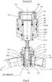
- the expansion cone 121 is secured to the end of the hollow rod 1223 of a jack making it possible to move the expansion cone 121 in translation inside the conical bore 1202.
- Peripheral slots 1221 pass through the rod 1223 allowing the evacuation of shavings during a drilling operation. These lights 1221 extend opposite the lights 1010 formed in the body 10.
- the longitudinal axis of the cylinder rod 1223 extends co-axially with the drilling barrel.
- the rod 1223 carries transverse pins 1222 which are each housed in a longitudinal groove 1014 formed for this purpose in the body 10.
- the pins 1222 and the grooves 1014 make it possible to block in rotation the rod 1223 relative to the body 10 and to allow the translation of the rod 1223 in the body 10 along its longitudinal axis.
- the rod 1223 carries a piston 1224 housed in the bore 1220. It extends on one side of the piston 1224 in a bore 1015 formed in the body 10 and emerging in the bore 1220. It extends on the other side of the piston 1224 in a bore 143 formed in the plug 14.
- the bores 1015 and 143 each have a peripheral groove 1016, 144 housing an O-ring 1017, 145 making it possible, with the seal 140, to seal the bore 1220 which constitutes the cylinder of a cylinder inside which the piston 1224 is mounted movable in translation.
- the piston 1224 delimits inside the cylinder 1220 a locking chamber 12201 and a release chamber 12202.
- the surface of the face of the piston located in the unlocking chamber is greater than the surface of the face of said piston located in said unlocking chamber locking.
- the body 10 is crossed by a locking channel 1225 and by a release channel 1226 opening respectively into the locking chamber 12201 and into the release chamber 12202 and making it possible to supply them with pressurized fluid.
- the locking channel 1225 and the release channel 1226 are respectively connected to a locking pipe 1227 and a release pipe 1228 intended to be connected to means for supplying pressurized fluid.
- the guide ring 124 is traversed by an internal bore 1240 inside which is formed a peripheral internal blocking housing 1241 which is in the form of a groove. It has a cylindrical outer contour extended by a shoulder 1242.
- each positioning bore 131 comprises two internal portions bored 1310, 1311 of different diameters to the interface from which a shoulder 1312 is formed.
- the shoulder 1312 is formed on the side of the piercing grid 13 located opposite the side against which the stop 151 is intended to come to bear.
- the guide ring 124 thus has an external shape complementary to the internal shape of the positioning bore 131.
- the expandable ring 120 is intended to be housed in a positioning bore (the positioning bore 131 of the grid or the internal bore 1240 of the ring guide 124) integral with the drilling grid 13.
- a positioning bore the positioning bore 131 of the grid or the internal bore 1240 of the ring guide 1204.
- the jack makes it possible to move the piston 1224 and the cone 121 integral with its rod 1223 from one to the other of its positions.
- the balls 123 are located against the first stage 12100 of the corresponding groove 1210 in the unlocked position and against the second stage 12101 in the blocked position.
- the securing device comprises means for regulating the drive means in translation of the expansion cone, that is to say of the jack.
- These regulation means are configured so that the translational movement speed imparted to the expansion cone by the jack is lower during its passage from the release position to the blocking position than that during its passage from the blocking position to the release position.
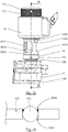
- the fastening device is traversed right through by a piercing barrel 16 which allows the rotation and translation movement of a spindle and the cutting tool secured at its end during a drilling operation.
- a chipbreaker 17 is placed at the rear end of the drilling barrel 16.
- a securing device 1 according to the invention is firstly secured at the end of a piercing device.
- a knurled nut 110 is threaded at the end of the housing of the piercing device and then a ring 141 is secured to the end of the housing of the piercing device so as to be stationary relative thereto. It can for example be force-fitted and / or glued to the end of the piercing device.
- the knurled nut 110 is held integral with the drilling device by the ring 141.
- This nut is movable in rotation relative to the casing of the drilling device, as well as in translation until it comes to bear against the ring 141.
- the body 10 of the securing device is brought closer to the end of the piercing device so as to introduce the ring 141 until it comes into abutment against the shoulder 142 of the plug 14. Then the knurled nut 110 is screwed onto the threaded portion 113 of complementary shape provided for this purpose on the plug 14 of the securing device until the ring 141 is compressed between the shoulder 142 of the plug 14 and the shoulder 114 of the knurled nut 110. The securing device is then fixed to the piercing device so that they are immobilized relative to each other.
- the figure 12 illustrates a securing device 1 fixed to the end of a drilling tool 2 shown partially and schematically.
- the spindle of the piercing device as well as possibly the cutting tool which could already be secured to it, then extends (s) in the longitudinal axis of the fastening device, if necessary in part to the inside the drill barrel 16.
- the locking 1227 and release 1228 pipes are then connected to the pressurized fluid supply network, in particular compressed air, of the drilling device.
- the jack is then controlled so as to place the expansion cone 121 in its release position, the locking balls 123 in their unlocking position and the expanding ring 120 in its released state if they were not in this position. / state (cf. figures 5 and 6 ).
- the pressurized fluid is introduced into the release chamber 12202 via the release line 1228.
- the piston 1224 translates inside the cylinder 1220 along the longitudinal axis of the piston in the direction of the end of the attachment device 1 intended to be attached to a drilling grid (see arrow D).
- the piston rod 1223 follows the translational movement of the piston 1224 so that the expansion cone 121 is translated relative to the expandable ring 120 to be placed in its release position in which its large diameter end is distant from the end of large diameter of the conical bore 1202 of the expandable ring 120.
- the expansion cone 121 does not act on the expandable ring 120.
- the expandable ring 120 is then in its relaxed state in which its outer diameter is smaller than the internal diameter of the positioning bores 131 of the drilling grille 13, or of the internal bores 1240 of the guide rings 124 when they are used.
- the locking balls 123 roll on the surface of the expansion cone 121 in their respective grooves 1210 first against the second stage 12101, then against the inclined ramp 12102, to come into contact with the first floor 12100.
- the locking balls 123 move freely in translation inside the radial orifices 1203, along their longitudinal axis, until they are placed in their unlocked position in which they do not protrude at the surface of the expandable ring 120.
- the guide rings 124 are optionally forced into the positioning bores 131 of the drilling grid 13, from the face 133 of the grid oriented towards the side of the element to be drilled, until their shoulder 1242 comes to bear against the shoulder 1312 of the corresponding positioning bore 131.
- each positioning ring 124 oriented towards the side of the surface 132 of the grid against which the stop 151 is intended to come into abutment then forms slightly protruding from this surface by a few tenths of a millimeter.
- the piercing device and the fastening device which is attached to it are then moved so as to introduce the expanding ring 120 into the internal bore 1240 of the guide ring 124 of the piercing grid corresponding to the location at which it is desired. drilling, until the stop 151 is in abutment against the guide ring 124 if such rings are used or against the surface 132 of the drilling grid 13 oriented towards the side of the tool drilling, that is to say on the side opposite the side of the grid facing the element to be drilled.
- This movement can be carried out manually by an operator or by means of a manipulator arm (robot arm) if the piercing device is secured to the end of such an arm.
- Pressurized fluid is then admitted via the locking pipe 1127 into the locking chamber 12201 to place the expansion cone 121 in its locked position, the expandable ring in its expanded state and the locking balls 123 in their position blocking (cf. figures 8 and 9 ).
- the piston 1224 translates inside the cylinder 1220 along the longitudinal axis of the piston in the direction of the end of the attachment device intended to be attached to a device drilling (see arrow V).
- the piston rod 1223 follows the translational movement of the piston 1224 so that the expansion cone 121 translates relative to the expandable ring 120 to place itself in its locking position in which its large diameter end is brought closer to the end of large diameter of the conical bore 1202 of the expandable ring 120.
- the expansion cone 121 thus acts on the expandable ring 120.
- the expandable ring 120 is then in its expanded state in which its outside diameter is increased until the expanding ring 120 compresses against the internal bore 1240 of the corresponding guide ring 124 or against the internal wall of the grid positioning bore if no guide ring is fitted implemented.
- the securing device is thus held integral with the drilling grid under the effect of friction between the expandable ring and the guide ring or, where appropriate, the positioning bore.
- the locking balls 123 roll on the surface of the expansion cone 121 in their respective grooves 1210 first against the first stage 12100, then against the inclined ramp 12102, to come into contact with the second floor 12101.
- the locking balls 123 move in translation inside the radial orifices 1203, along their longitudinal axis, until they are placed in their blocking position in which they protrude from the surface of the expandable ring 120 so that they are introduced into the inner peripheral blocking housing 1241 of the corresponding guide ring 124 or directly formed in the corresponding positioning bore if no guide ring is used.
- the locking balls 123 associated with the inner peripheral blocking housing 1241 make it possible to ensure a translation locking of the fastening device relative to the drilling grid, and thus to avoid any displacement in translation of the drilling device relative to the grid along the drilling axis during a drilling operation.
- the introduction of the locking balls 123 into the inner peripheral blocking housing 1241 of the guide ring 124 tends to induce a compressive force of the shoulder 1242 of the guide ring 124 against the shoulder 1312 of the drilling grid, as well as a compression force of the end of the guide ring 124 against the stop 151.
- Such an attachment does not require feeding the cylinder with a very high pressure. A pressure of around 6 bars is sufficient.
- a drilling operation can then be launched.
- the spindle and the cutting tool placed at its end move in translation and in rotation along the same axis inside the drilling barrel 16.
- a chipbreaker 17, optionally placed at the end of the drilling barrel 16 makes it possible to break the chip formed during drilling and to guide it inside the drilling barrel in the direction of the slots 1221 and 1010 formed respectively in the rod 1223 and into the body 10 in order to be evacuated.
- a suction nozzle 18 may have been previously secured to the body 10 opposite the lights 1221 and 1010 to suck the chips and evacuate them to a storage and / or treatment area.
- a protective ring 19, crossed by peripheral ports 190, may optionally have been able to be interposed between the body 10 and the suction nozzle 18, to prevent an operator from being able to introduce the fingers into the ports 1221 and 1010.
- the unlocking chamber 12202 is again pressurized with compressed fluid to generate the unlocking of the device according to the procedure described above.
- the admission of the compressed fluid into the cylinder is regulated in such a way that the speed of the piston to move towards its locking position is higher than that to move to its release position. This makes it possible to guarantee that the cutting tool has come out of the piercing grid before the detaching device can be detached from the piercing grid. This avoids breaking the cutting tool when the drilling device is detached.
- the pipes 1227, 1228 are preferably connected downstream of the actuating trigger or of the actuating valve making it possible to supply the motor of the drilling device when a drilling operation is activated.
- the start of a drilling operation is synchronized with the locking of the fastening device so as to guarantee that the drilling operation begins after the fastening of the drilling device, and vice versa.
- an expandable collar ring could be implemented.
- This flange could be housed in a housing of complementary shape formed directly in a positioning bore or in a guide ring like the locking balls. Alternatively, this flange could bear against the surface of the grid placed on the side of the element to be drilled.
- the locking balls and the flange constitute means for blocking in translation the fastening device relative to the grid along the drilling axis.
- the direction of movement of the expansion cone to move from its release position to its locking position may be reversed. In this case, it will pass from its release position to its locking position by being translated towards the surface of the drilling grid oriented towards the element to be drilled.
- the balls may first of all come into contact with the edge of the peripheral blocking housing oriented towards the piercing device.
- the balls will thus be housed in the peripheral blocking housing by generating an axial force which tends to compress the stop against the grid or the guide ring.
- the balls can be directly housed in peripheral blocking housing without generating axial force.
Landscapes
- Engineering & Computer Science (AREA)
- Mechanical Engineering (AREA)
- Processing Of Stones Or Stones Resemblance Materials (AREA)
- Drilling Tools (AREA)
- Drilling And Boring (AREA)
- Earth Drilling (AREA)
Applications Claiming Priority (1)
| Application Number | Priority Date | Filing Date | Title |
|---|---|---|---|
| FR1872722A FR3089441B1 (fr) | 2018-12-11 | 2018-12-11 | Dispositif de solidarisation d’un dispositif de perçage à une grille de perçage comprenant un moyeu expansible à billes |
Publications (2)
| Publication Number | Publication Date |
|---|---|
| EP3666432A1 true EP3666432A1 (de) | 2020-06-17 |
| EP3666432B1 EP3666432B1 (de) | 2021-11-03 |
Family
ID=66542357
Family Applications (1)
| Application Number | Title | Priority Date | Filing Date |
|---|---|---|---|
| EP19212196.0A Active EP3666432B1 (de) | 2018-12-11 | 2019-11-28 | Vorrichtung zur festen verbindung einer bohrvorrichtung mit einem bohrgitter, das einen kugelspannsatz umfasst |
Country Status (3)
| Country | Link |
|---|---|
| US (1) | US11298755B2 (de) |
| EP (1) | EP3666432B1 (de) |
| FR (1) | FR3089441B1 (de) |
Cited By (1)
| Publication number | Priority date | Publication date | Assignee | Title |
|---|---|---|---|---|
| WO2025181268A1 (fr) * | 2024-03-01 | 2025-09-04 | Seti-Tec | Dispositif de perçage à moyen d'immobilisation actionnables par un moteur d'entrainement de la broche de perçage |
Families Citing this family (2)
| Publication number | Priority date | Publication date | Assignee | Title |
|---|---|---|---|---|
| FR3097146B1 (fr) * | 2019-06-17 | 2021-06-04 | Advanced Electrical Tools | Outil de perçage |
| CN116673519B (zh) * | 2023-04-24 | 2026-03-31 | 天津爱思达航天科技股份有限公司 | 一种整流罩对接结构打孔装置及打孔方法 |
Citations (5)
| Publication number | Priority date | Publication date | Assignee | Title |
|---|---|---|---|---|
| US5395187A (en) * | 1993-11-22 | 1995-03-07 | Mcdonnell Douglas Corporation | Method and apparatus for attaching a drill motor to a drill plate with a clamping device having an expandable collet |
| US5482411A (en) * | 1994-12-22 | 1996-01-09 | Mcdonnell Douglas Corporation | Method and apparatus for securely clamping a drill motor to a drill plate |
| US20040223821A1 (en) * | 2003-05-06 | 2004-11-11 | The Boeing Company | Locking nosepiece and template |
| WO2008133586A1 (en) * | 2007-04-27 | 2008-11-06 | Novator Ab | Fixation device for a portable drilling unit |
| US20120328382A1 (en) * | 2011-06-22 | 2012-12-27 | Sugino Machine Limited | Clamping device, clamping method, and hole drilling method |
Family Cites Families (8)
| Publication number | Priority date | Publication date | Assignee | Title |
|---|---|---|---|---|
| US2839953A (en) * | 1955-10-24 | 1958-06-24 | Boeing Co | Drill motor collet mounts |
| US2935905A (en) * | 1956-12-10 | 1960-05-10 | Winslow Product Engineering Co | Collet foot attachment for pneumatic power drill |
| FR2562179B1 (fr) * | 1984-04-02 | 1986-08-14 | Recoules Fils | Dispositif de fixation automatique d'un outillage sur un support |
| US5628592A (en) * | 1995-08-31 | 1997-05-13 | Cooper Industries, Inc. | Two-piece concentric collet |
| US6012877A (en) * | 1996-12-13 | 2000-01-11 | The Boeing Company | Self-centering end effector |
| FR2934966B1 (fr) * | 2008-08-12 | 2010-09-17 | Airbus France | Systeme de percage et procede |
| FR2969518B1 (fr) * | 2010-12-22 | 2014-02-21 | Cooper Power Tools Sas | Dispositif de positionnement d'une machine d'usinage sur un support vis-a-vis d'une piece a usiner |
| FR3022167B1 (fr) * | 2014-06-17 | 2016-07-15 | Cinetic Machining | Machine de percage et/ou alesage, notamment pour des pieces composant des structures d'avion |
-
2018
- 2018-12-11 FR FR1872722A patent/FR3089441B1/fr not_active Expired - Fee Related
-
2019
- 2019-11-28 EP EP19212196.0A patent/EP3666432B1/de active Active
- 2019-12-10 US US16/709,282 patent/US11298755B2/en active Active
Patent Citations (5)
| Publication number | Priority date | Publication date | Assignee | Title |
|---|---|---|---|---|
| US5395187A (en) * | 1993-11-22 | 1995-03-07 | Mcdonnell Douglas Corporation | Method and apparatus for attaching a drill motor to a drill plate with a clamping device having an expandable collet |
| US5482411A (en) * | 1994-12-22 | 1996-01-09 | Mcdonnell Douglas Corporation | Method and apparatus for securely clamping a drill motor to a drill plate |
| US20040223821A1 (en) * | 2003-05-06 | 2004-11-11 | The Boeing Company | Locking nosepiece and template |
| WO2008133586A1 (en) * | 2007-04-27 | 2008-11-06 | Novator Ab | Fixation device for a portable drilling unit |
| US20120328382A1 (en) * | 2011-06-22 | 2012-12-27 | Sugino Machine Limited | Clamping device, clamping method, and hole drilling method |
Cited By (2)
| Publication number | Priority date | Publication date | Assignee | Title |
|---|---|---|---|---|
| WO2025181268A1 (fr) * | 2024-03-01 | 2025-09-04 | Seti-Tec | Dispositif de perçage à moyen d'immobilisation actionnables par un moteur d'entrainement de la broche de perçage |
| FR3159757A1 (fr) * | 2024-03-01 | 2025-09-05 | Seti-Tec | Dispositif de perçage à moyen d’immobilisation actionnables par un moteur d’entrainement de la broche de perçage |
Also Published As
| Publication number | Publication date |
|---|---|
| EP3666432B1 (de) | 2021-11-03 |
| FR3089441B1 (fr) | 2021-04-02 |
| FR3089441A1 (fr) | 2020-06-12 |
| US20200180046A1 (en) | 2020-06-11 |
| US11298755B2 (en) | 2022-04-12 |
Similar Documents
| Publication | Publication Date | Title |
|---|---|---|
| EP2105249B1 (de) | Bearbeitungsmaschine mit mechanischem Vorschub und Bearbeitungsverfahren | |
| EP3666432B1 (de) | Vorrichtung zur festen verbindung einer bohrvorrichtung mit einem bohrgitter, das einen kugelspannsatz umfasst | |
| EP1023522B1 (de) | Kernbohrgerät | |
| FR2912672A1 (fr) | Procede d'assemblage de deux ensembles, tels que des ensembles de fuselage d'aeronef | |
| FR2738281A1 (fr) | Systeme de prevention d'explosion equipe de verrous de belier | |
| FR2482887A1 (fr) | Porte-outil integre a une broche de machine-outil d'usinage par outil tournant | |
| EP0340369B1 (de) | Vorrichtung zur Befestigung von Werkzeughaltern und Werkzeugen mit konischen und planen Tragflächen, insbesondere für Bearbeitungszentren mit automatischen oder manuellen Werkzeugwechslern | |
| EP2285534B1 (de) | Werzeug zum anbringen von drahtgewindeeinsätzen mit verriegelungskeil und kit mit diesem werkzeug | |
| FR3018267A1 (fr) | Dispositif de positionnement relatif de deux pieces telles qu'une traverse et un cadre de fuselage | |
| EP3306167B1 (de) | Schnellverbinder | |
| EP0346231B1 (de) | Bohrmaschine, insbesondere für programmierbare Maschine | |
| EP2498938B1 (de) | Gewindebohrer mit schutzmittel | |
| EP2977142B1 (de) | Verfahren zur ordnungsgemässen wiederinstandsetzung von felgen, und werkzeug für die umsetzung dieses verfahrens | |
| EP3434400B1 (de) | Bohrmaschine, die mechanische mittel zur regulierung des schmiermitteldurchsatzes in abhängigkeit von den schnittleistungen umfasst | |
| EP2500137B1 (de) | Schnellverschlussspindel | |
| EP3682992B1 (de) | Vorrichtung zum bohren einer kanalisation | |
| EP1525096A2 (de) | Verbesserungen in druckmaschinen | |
| EP1844897A1 (de) | System zur Absaugung von Spänen und/oder Staub für den Kopf einer Fräsmaschine mit automatischem Werkstückwechsel | |
| CH684391A5 (fr) | Procédé et dispositif pour la mise en place d'un joint torique dans une gorge. | |
| FR3065179A1 (fr) | Dispositif formant effecteur pour percage orbital, destine a etre monte sur un bras de robot ou sur une unite portative automatique | |
| FR2953438A1 (fr) | Dispositif de percage | |
| EP0090224B1 (de) | Spannvorrichtung eines Schneideneinsatzes auf einem Werkzeughalter | |
| FR3157823A1 (fr) | dispositif de perçage à débrayage de l’avance en fin de rétractation | |
| FR2653363A1 (fr) | Ensemble d'usinage pour executer une multiplicite de trous dans une structure, telle que cellule d'avion, avec une grille munie de canons et au moins une machine de percage. | |
| FR3159757A1 (fr) | Dispositif de perçage à moyen d’immobilisation actionnables par un moteur d’entrainement de la broche de perçage |
Legal Events
| Date | Code | Title | Description |
|---|---|---|---|
| PUAI | Public reference made under article 153(3) epc to a published international application that has entered the european phase |
Free format text: ORIGINAL CODE: 0009012 |
|
| STAA | Information on the status of an ep patent application or granted ep patent |
Free format text: STATUS: THE APPLICATION HAS BEEN PUBLISHED |
|
| AK | Designated contracting states |
Kind code of ref document: A1 Designated state(s): AL AT BE BG CH CY CZ DE DK EE ES FI FR GB GR HR HU IE IS IT LI LT LU LV MC MK MT NL NO PL PT RO RS SE SI SK SM TR |
|
| AX | Request for extension of the european patent |
Extension state: BA ME |
|
| STAA | Information on the status of an ep patent application or granted ep patent |
Free format text: STATUS: REQUEST FOR EXAMINATION WAS MADE |
|
| 17P | Request for examination filed |
Effective date: 20200612 |
|
| RBV | Designated contracting states (corrected) |
Designated state(s): AL AT BE BG CH CY CZ DE DK EE ES FI FR GB GR HR HU IE IS IT LI LT LU LV MC MK MT NL NO PL PT RO RS SE SI SK SM TR |
|
| GRAP | Despatch of communication of intention to grant a patent |
Free format text: ORIGINAL CODE: EPIDOSNIGR1 |
|
| STAA | Information on the status of an ep patent application or granted ep patent |
Free format text: STATUS: GRANT OF PATENT IS INTENDED |
|
| INTG | Intention to grant announced |
Effective date: 20210115 |
|
| GRAS | Grant fee paid |
Free format text: ORIGINAL CODE: EPIDOSNIGR3 |
|
| GRAJ | Information related to disapproval of communication of intention to grant by the applicant or resumption of examination proceedings by the epo deleted |
Free format text: ORIGINAL CODE: EPIDOSDIGR1 |
|
| GRAL | Information related to payment of fee for publishing/printing deleted |
Free format text: ORIGINAL CODE: EPIDOSDIGR3 |
|
| STAA | Information on the status of an ep patent application or granted ep patent |
Free format text: STATUS: REQUEST FOR EXAMINATION WAS MADE |
|
| GRAP | Despatch of communication of intention to grant a patent |
Free format text: ORIGINAL CODE: EPIDOSNIGR1 |
|
| INTC | Intention to grant announced (deleted) | ||
| STAA | Information on the status of an ep patent application or granted ep patent |
Free format text: STATUS: GRANT OF PATENT IS INTENDED |
|
| INTG | Intention to grant announced |
Effective date: 20210609 |
|
| GRAA | (expected) grant |
Free format text: ORIGINAL CODE: 0009210 |
|
| STAA | Information on the status of an ep patent application or granted ep patent |
Free format text: STATUS: THE PATENT HAS BEEN GRANTED |
|
| AK | Designated contracting states |
Kind code of ref document: B1 Designated state(s): AL AT BE BG CH CY CZ DE DK EE ES FI FR GB GR HR HU IE IS IT LI LT LU LV MC MK MT NL NO PL PT RO RS SE SI SK SM TR |
|
| REG | Reference to a national code |
Ref country code: GB Ref legal event code: FG4D Free format text: NOT ENGLISH |
|
| REG | Reference to a national code |
Ref country code: AT Ref legal event code: REF Ref document number: 1443523 Country of ref document: AT Kind code of ref document: T Effective date: 20211115 Ref country code: CH Ref legal event code: EP |
|
| REG | Reference to a national code |
Ref country code: IE Ref legal event code: FG4D Free format text: LANGUAGE OF EP DOCUMENT: FRENCH |
|
| REG | Reference to a national code |
Ref country code: DE Ref legal event code: R096 Ref document number: 602019008931 Country of ref document: DE |
|
| REG | Reference to a national code |
Ref country code: LT Ref legal event code: MG9D |
|
| REG | Reference to a national code |
Ref country code: NL Ref legal event code: MP Effective date: 20211103 |
|
| REG | Reference to a national code |
Ref country code: AT Ref legal event code: MK05 Ref document number: 1443523 Country of ref document: AT Kind code of ref document: T Effective date: 20211103 |
|
| PG25 | Lapsed in a contracting state [announced via postgrant information from national office to epo] |
Ref country code: RS Free format text: LAPSE BECAUSE OF FAILURE TO SUBMIT A TRANSLATION OF THE DESCRIPTION OR TO PAY THE FEE WITHIN THE PRESCRIBED TIME-LIMIT Effective date: 20211103 Ref country code: LT Free format text: LAPSE BECAUSE OF FAILURE TO SUBMIT A TRANSLATION OF THE DESCRIPTION OR TO PAY THE FEE WITHIN THE PRESCRIBED TIME-LIMIT Effective date: 20211103 Ref country code: FI Free format text: LAPSE BECAUSE OF FAILURE TO SUBMIT A TRANSLATION OF THE DESCRIPTION OR TO PAY THE FEE WITHIN THE PRESCRIBED TIME-LIMIT Effective date: 20211103 Ref country code: BG Free format text: LAPSE BECAUSE OF FAILURE TO SUBMIT A TRANSLATION OF THE DESCRIPTION OR TO PAY THE FEE WITHIN THE PRESCRIBED TIME-LIMIT Effective date: 20220203 Ref country code: AT Free format text: LAPSE BECAUSE OF FAILURE TO SUBMIT A TRANSLATION OF THE DESCRIPTION OR TO PAY THE FEE WITHIN THE PRESCRIBED TIME-LIMIT Effective date: 20211103 |
|
| PG25 | Lapsed in a contracting state [announced via postgrant information from national office to epo] |
Ref country code: IS Free format text: LAPSE BECAUSE OF FAILURE TO SUBMIT A TRANSLATION OF THE DESCRIPTION OR TO PAY THE FEE WITHIN THE PRESCRIBED TIME-LIMIT Effective date: 20220303 Ref country code: SE Free format text: LAPSE BECAUSE OF FAILURE TO SUBMIT A TRANSLATION OF THE DESCRIPTION OR TO PAY THE FEE WITHIN THE PRESCRIBED TIME-LIMIT Effective date: 20211103 Ref country code: PT Free format text: LAPSE BECAUSE OF FAILURE TO SUBMIT A TRANSLATION OF THE DESCRIPTION OR TO PAY THE FEE WITHIN THE PRESCRIBED TIME-LIMIT Effective date: 20220303 Ref country code: PL Free format text: LAPSE BECAUSE OF FAILURE TO SUBMIT A TRANSLATION OF THE DESCRIPTION OR TO PAY THE FEE WITHIN THE PRESCRIBED TIME-LIMIT Effective date: 20211103 Ref country code: NO Free format text: LAPSE BECAUSE OF FAILURE TO SUBMIT A TRANSLATION OF THE DESCRIPTION OR TO PAY THE FEE WITHIN THE PRESCRIBED TIME-LIMIT Effective date: 20220203 Ref country code: NL Free format text: LAPSE BECAUSE OF FAILURE TO SUBMIT A TRANSLATION OF THE DESCRIPTION OR TO PAY THE FEE WITHIN THE PRESCRIBED TIME-LIMIT Effective date: 20211103 Ref country code: LV Free format text: LAPSE BECAUSE OF FAILURE TO SUBMIT A TRANSLATION OF THE DESCRIPTION OR TO PAY THE FEE WITHIN THE PRESCRIBED TIME-LIMIT Effective date: 20211103 Ref country code: HR Free format text: LAPSE BECAUSE OF FAILURE TO SUBMIT A TRANSLATION OF THE DESCRIPTION OR TO PAY THE FEE WITHIN THE PRESCRIBED TIME-LIMIT Effective date: 20211103 Ref country code: GR Free format text: LAPSE BECAUSE OF FAILURE TO SUBMIT A TRANSLATION OF THE DESCRIPTION OR TO PAY THE FEE WITHIN THE PRESCRIBED TIME-LIMIT Effective date: 20220204 Ref country code: ES Free format text: LAPSE BECAUSE OF FAILURE TO SUBMIT A TRANSLATION OF THE DESCRIPTION OR TO PAY THE FEE WITHIN THE PRESCRIBED TIME-LIMIT Effective date: 20211103 |
|
| PG25 | Lapsed in a contracting state [announced via postgrant information from national office to epo] |
Ref country code: SM Free format text: LAPSE BECAUSE OF FAILURE TO SUBMIT A TRANSLATION OF THE DESCRIPTION OR TO PAY THE FEE WITHIN THE PRESCRIBED TIME-LIMIT Effective date: 20211103 Ref country code: SK Free format text: LAPSE BECAUSE OF FAILURE TO SUBMIT A TRANSLATION OF THE DESCRIPTION OR TO PAY THE FEE WITHIN THE PRESCRIBED TIME-LIMIT Effective date: 20211103 Ref country code: RO Free format text: LAPSE BECAUSE OF FAILURE TO SUBMIT A TRANSLATION OF THE DESCRIPTION OR TO PAY THE FEE WITHIN THE PRESCRIBED TIME-LIMIT Effective date: 20211103 Ref country code: LU Free format text: LAPSE BECAUSE OF NON-PAYMENT OF DUE FEES Effective date: 20211128 Ref country code: EE Free format text: LAPSE BECAUSE OF FAILURE TO SUBMIT A TRANSLATION OF THE DESCRIPTION OR TO PAY THE FEE WITHIN THE PRESCRIBED TIME-LIMIT Effective date: 20211103 Ref country code: DK Free format text: LAPSE BECAUSE OF FAILURE TO SUBMIT A TRANSLATION OF THE DESCRIPTION OR TO PAY THE FEE WITHIN THE PRESCRIBED TIME-LIMIT Effective date: 20211103 Ref country code: CZ Free format text: LAPSE BECAUSE OF FAILURE TO SUBMIT A TRANSLATION OF THE DESCRIPTION OR TO PAY THE FEE WITHIN THE PRESCRIBED TIME-LIMIT Effective date: 20211103 Ref country code: BE Free format text: LAPSE BECAUSE OF NON-PAYMENT OF DUE FEES Effective date: 20211130 |
|
| REG | Reference to a national code |
Ref country code: BE Ref legal event code: MM Effective date: 20211130 |
|
| REG | Reference to a national code |
Ref country code: DE Ref legal event code: R097 Ref document number: 602019008931 Country of ref document: DE |
|
| PG25 | Lapsed in a contracting state [announced via postgrant information from national office to epo] |
Ref country code: MC Free format text: LAPSE BECAUSE OF FAILURE TO SUBMIT A TRANSLATION OF THE DESCRIPTION OR TO PAY THE FEE WITHIN THE PRESCRIBED TIME-LIMIT Effective date: 20211103 |
|
| PLBE | No opposition filed within time limit |
Free format text: ORIGINAL CODE: 0009261 |
|
| STAA | Information on the status of an ep patent application or granted ep patent |
Free format text: STATUS: NO OPPOSITION FILED WITHIN TIME LIMIT |
|
| 26N | No opposition filed |
Effective date: 20220804 |
|
| PG25 | Lapsed in a contracting state [announced via postgrant information from national office to epo] |
Ref country code: IE Free format text: LAPSE BECAUSE OF NON-PAYMENT OF DUE FEES Effective date: 20211128 Ref country code: AL Free format text: LAPSE BECAUSE OF FAILURE TO SUBMIT A TRANSLATION OF THE DESCRIPTION OR TO PAY THE FEE WITHIN THE PRESCRIBED TIME-LIMIT Effective date: 20211103 |
|
| PG25 | Lapsed in a contracting state [announced via postgrant information from national office to epo] |
Ref country code: SI Free format text: LAPSE BECAUSE OF FAILURE TO SUBMIT A TRANSLATION OF THE DESCRIPTION OR TO PAY THE FEE WITHIN THE PRESCRIBED TIME-LIMIT Effective date: 20211103 |
|
| PG25 | Lapsed in a contracting state [announced via postgrant information from national office to epo] |
Ref country code: IT Free format text: LAPSE BECAUSE OF FAILURE TO SUBMIT A TRANSLATION OF THE DESCRIPTION OR TO PAY THE FEE WITHIN THE PRESCRIBED TIME-LIMIT Effective date: 20211103 |
|
| PG25 | Lapsed in a contracting state [announced via postgrant information from national office to epo] |
Ref country code: CY Free format text: LAPSE BECAUSE OF FAILURE TO SUBMIT A TRANSLATION OF THE DESCRIPTION OR TO PAY THE FEE WITHIN THE PRESCRIBED TIME-LIMIT Effective date: 20211103 |
|
| REG | Reference to a national code |
Ref country code: CH Ref legal event code: PL |
|
| PG25 | Lapsed in a contracting state [announced via postgrant information from national office to epo] |
Ref country code: LI Free format text: LAPSE BECAUSE OF NON-PAYMENT OF DUE FEES Effective date: 20221130 Ref country code: HU Free format text: LAPSE BECAUSE OF FAILURE TO SUBMIT A TRANSLATION OF THE DESCRIPTION OR TO PAY THE FEE WITHIN THE PRESCRIBED TIME-LIMIT; INVALID AB INITIO Effective date: 20191128 Ref country code: CH Free format text: LAPSE BECAUSE OF NON-PAYMENT OF DUE FEES Effective date: 20221130 |
|
| PG25 | Lapsed in a contracting state [announced via postgrant information from national office to epo] |
Ref country code: MK Free format text: LAPSE BECAUSE OF FAILURE TO SUBMIT A TRANSLATION OF THE DESCRIPTION OR TO PAY THE FEE WITHIN THE PRESCRIBED TIME-LIMIT Effective date: 20211103 |
|
| PG25 | Lapsed in a contracting state [announced via postgrant information from national office to epo] |
Ref country code: MT Free format text: LAPSE BECAUSE OF FAILURE TO SUBMIT A TRANSLATION OF THE DESCRIPTION OR TO PAY THE FEE WITHIN THE PRESCRIBED TIME-LIMIT Effective date: 20211103 |
|
| PG25 | Lapsed in a contracting state [announced via postgrant information from national office to epo] |
Ref country code: TR Free format text: LAPSE BECAUSE OF FAILURE TO SUBMIT A TRANSLATION OF THE DESCRIPTION OR TO PAY THE FEE WITHIN THE PRESCRIBED TIME-LIMIT Effective date: 20211103 |
|
| PGFP | Annual fee paid to national office [announced via postgrant information from national office to epo] |
Ref country code: DE Payment date: 20251126 Year of fee payment: 7 |
|
| PGFP | Annual fee paid to national office [announced via postgrant information from national office to epo] |
Ref country code: GB Payment date: 20251128 Year of fee payment: 7 |
|
| PGFP | Annual fee paid to national office [announced via postgrant information from national office to epo] |
Ref country code: FR Payment date: 20251125 Year of fee payment: 7 |