EP3666433A1 - Outil de perçage - Google Patents
Outil de perçage Download PDFInfo
- Publication number
- EP3666433A1 EP3666433A1 EP18212364.6A EP18212364A EP3666433A1 EP 3666433 A1 EP3666433 A1 EP 3666433A1 EP 18212364 A EP18212364 A EP 18212364A EP 3666433 A1 EP3666433 A1 EP 3666433A1
- Authority
- EP
- European Patent Office
- Prior art keywords
- drilling tool
- chip space
- drill
- flutes
- section
- Prior art date
- Legal status (The legal status is an assumption and is not a legal conclusion. Google has not performed a legal analysis and makes no representation as to the accuracy of the status listed.)
- Granted
Links
Images


Classifications
-
- B—PERFORMING OPERATIONS; TRANSPORTING
- B23—MACHINE TOOLS; METAL-WORKING NOT OTHERWISE PROVIDED FOR
- B23B—TURNING; BORING
- B23B51/00—Tools for drilling machines
- B23B51/02—Twist drills
-
- B—PERFORMING OPERATIONS; TRANSPORTING
- B23—MACHINE TOOLS; METAL-WORKING NOT OTHERWISE PROVIDED FOR
- B23B—TURNING; BORING
- B23B51/00—Tools for drilling machines
- B23B51/06—Drills with lubricating or cooling equipment
-
- B—PERFORMING OPERATIONS; TRANSPORTING
- B24—GRINDING; POLISHING
- B24B—MACHINES, DEVICES, OR PROCESSES FOR GRINDING OR POLISHING; DRESSING OR CONDITIONING OF ABRADING SURFACES; FEEDING OF GRINDING, POLISHING, OR LAPPING AGENTS
- B24B19/00—Single-purpose machines or devices for particular grinding operations not covered by any other main group
- B24B19/02—Single-purpose machines or devices for particular grinding operations not covered by any other main group for grinding grooves, e.g. on shafts, in casings, in tubes, homokinetic joint elements
- B24B19/022—Single-purpose machines or devices for particular grinding operations not covered by any other main group for grinding grooves, e.g. on shafts, in casings, in tubes, homokinetic joint elements for helicoidal grooves
-
- B—PERFORMING OPERATIONS; TRANSPORTING
- B24—GRINDING; POLISHING
- B24B—MACHINES, DEVICES, OR PROCESSES FOR GRINDING OR POLISHING; DRESSING OR CONDITIONING OF ABRADING SURFACES; FEEDING OF GRINDING, POLISHING, OR LAPPING AGENTS
- B24B19/00—Single-purpose machines or devices for particular grinding operations not covered by any other main group
- B24B19/02—Single-purpose machines or devices for particular grinding operations not covered by any other main group for grinding grooves, e.g. on shafts, in casings, in tubes, homokinetic joint elements
- B24B19/04—Single-purpose machines or devices for particular grinding operations not covered by any other main group for grinding grooves, e.g. on shafts, in casings, in tubes, homokinetic joint elements for fluting drill shanks
-
- B—PERFORMING OPERATIONS; TRANSPORTING
- B23—MACHINE TOOLS; METAL-WORKING NOT OTHERWISE PROVIDED FOR
- B23B—TURNING; BORING
- B23B2251/00—Details of tools for drilling machines
- B23B2251/40—Flutes, i.e. chip conveying grooves
- B23B2251/406—Flutes, i.e. chip conveying grooves of special form not otherwise provided for
-
- B—PERFORMING OPERATIONS; TRANSPORTING
- B23—MACHINE TOOLS; METAL-WORKING NOT OTHERWISE PROVIDED FOR
- B23B—TURNING; BORING
- B23B2251/00—Details of tools for drilling machines
- B23B2251/44—Margins, i.e. the narrow portion of the land which is not cut away to provide clearance on the circumferential surface
- B23B2251/443—Double margin drills
Definitions
- the present invention relates to a drilling tool with the features of the preamble of claim 1.
- Generic drilling tools in particular twist drills, comprise a cylindrical base body on which helical webs and flutes are formed between webs.
- the angle at which the flutes are inclined to a central axis of the twist drill is the twist angle (also referred to as the helix angle) of the twist drill.
- the helix angle can vary over the length of the drill bit.
- twist drills have two helical flutes.
- the flutes allow chips to be removed.
- a chip space extension created in this way creates additional volume for picking up and removing chips.
- broadening of the chip space means that a free cross-section of a flute is enlarged compared to the actual tool grinding.
- the object of the present invention is to provide an improved drilling tool.
- the drilling tool according to the invention is designed in such a way that the chip space widening grips a web, so that a web width in the area of the chip space widening is reduced.
- the chip space of the tool is increased at the expense of the web.
- the web is therefore narrower in the area of the chip space expansion than in a section of the drilling tool in which no chip space expansion is formed.
- Chip space extensions from the prior art are designed as local depressions in chip flutes at the bottom.
- the creation of additional chip space by known chip space extensions is limited when the load-bearing cross-section of the drilling tool, ie the core diameter, is weakened.
- a chip space extension according to the invention extends a flute laterally by reducing a web width.
- additional chip space can be created by deepening the flute at the bottom.
- the expansion of the chip space according to the invention favors the removal of chips. A tendency to constipation is reduced.
- Chip space extensions are preferably formed on all flutes of the drilling tool. Of course, it can also be provided that a chip space extension is formed only on one flute. However, for a uniform mechanical load on the drilling tool, it is cheaper to provide chip space extensions on all flutes.
- the change in shape of the flute due to the expansion of the chip space according to the invention accelerates the chips, which promotes chip breakage.
- Acceleration is understood to mean that the chips experience a change in momentum.
- the change in momentum occurs primarily as a change in the direction of movement of the chips, that is to say through a chip deflection, due to the inventive configuration of the chip space extension.
- a web has a secondary cutting edge on the side lying in the direction of rotation.
- the web width is preferably reduced on the side of the web facing away from the secondary cutting edge, so that the shape of the secondary cutting edge remains unaffected by the expansion of the chip space. This ensures a smooth chip flow.
- the chip space extension is designed such that only the side of a web facing away from a direction of rotation is covered by the chip space extension.
- a further advantage of the invention is that a significant increase in the chip volume can be created within a short path.
- short path it is meant that the broadening of the chip space along a small angular range - based on a course of the helical flutes - or in other words, within a short distance - based on a longitudinal extension of the drilling tool - can be realized.
- the widening of the chip space preferably increases a slot opening angle of a flute.
- the slot opening angle is understood to mean that angle which the opposite flanks of a flute enclose with one another.
- the broadening of the chip space viewed from the drill face in the direction of the shank section, only begins at a distance from the drill face.
- the front part of the cutting section does not have an expansion of the chip space.
- the broadening of the chip space preferably begins at a distance from the drill face of greater than or equal to 1 ⁇ D, with D being the drill diameter.
- guide chamfers are formed on webs at least over part of the cutting section.
- Guide chamfers viewed from the drill face in the direction of the shaft section, are particularly preferred up to a distance from the drill face of less than or equal to 3 ⁇ D.
- two guide chamfers are formed on a web.
- the broadening of the chip space does not begin until after the area of the cutting section on which guide chamfers are formed. This has the advantage that the webs have their original width in the area of the guide chamfers, which is favorable for guiding or supporting the drill.
- the expansion of the chip space achieved by the broadening of the chip space increases along the longitudinal axis of the drill.
- the broadening of the chip space does not have to be constant, but can increase along the longitudinal axis of the drill. For mechanical reasons, it is favorable if the broadening of the chip space increases continuously, that is to say not abruptly.
- the increase in the chip space widening, based on a course of the chip flutes takes place within less than or equal to 360 °. This describes the characteristic already mentioned that the expansion of the chip space reaches the desired dimension within a short distance. At 360 °, the span expansion would increase from a start value to the desired final dimension within one revolution of a helical flute.
- the enlargement of the chip space extension can take place, for example, along a projected distance of less than or equal to 2.5 x the drill diameter D.
- the widening of the chip space increases along a first projected distance in the direction of the shaft section in order then to remain constant along a second projected distance in the direction of the shaft section.
- the broadening of the chip space is preferably designed as a ground joint. This means that the broadening of the chip space is preferably introduced by grinding. Alternatively, material could be removed by other methods, such as laser ablation.
- the flute has a variable depth in the area of the chip space expansion.
- depth is meant a distance from an outer surface of the drilling tool to the base of the flute.
- the depth can preferably increase in the direction of the shaft section. This also means that the depth and the lateral dimension of the chip space extension can be varied independently of one another.
- At least one coolant channel running in the interior of the drilling tool is formed.
- a coolant / lubricant can be delivered to the drill face via a coolant channel. This particularly advantageously supports the function of the drilling tool, since the coolant / lubricant further promotes removal of chips with reduced friction. The measures thus have a particularly advantageous effect on one another.
- the drilling tool is preferably formed from a composite material comprising at least one hard material and at least one binder phase.
- the drilling tool is made of hard metal.
- hard metal is understood to mean a composite material in which hard particles, which can be formed in particular by carbides, carbonitrides and / or oxocarbonitrides of the elements from groups IVb to VIb of the periodic table of the elements, are embedded in a ductile metallic matrix which is composed in particular of Co , Ni, Fe or an alloy of these can be formed.
- the hard particles are at least predominantly formed by tungsten carbide and the metallic matrix consists essentially of cobalt.
- Protection is also sought after for a method of making a drilling tool.
- a rotating grinding tool is moved along the flutes to create a widening of the chip space, a plane of rotation of the grinding tool being inclined at an angle to the longitudinal axis of the drill, which angle is greater than the helix angle of the corresponding flute.
- the grinding tool is guided in such a way that material is removed on those sides of the webs which are at the back with respect to a direction of rotation.
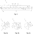
- Figure 1 shows a drilling tool 1 as a spiral drill with an essentially cylindrical base body with a drill diameter D, which has a shank section 2 and a cutting section 3.
- the shaft section 2 is only partially shown.
- the drilling tool 1 rotates in the direction of rotation R with the longitudinal axis L as the axis of rotation.
- the present drilling tool 1 is therefore clockwise.
- the drilling tool 1 has a drill face 4 (also: drill tip) on which main cutting edges are formed.
- Helical flutes 5 are formed along the drilling tool 1. In the present example, there are two diametrically opposite flutes 5. Alternatively, flutes 5 can also be arranged asymmetrically. More than two flutes 5 could also be provided.
- the flutes 5 run at a swirl angle ⁇ to the longitudinal axis L of the drilling tool 1. Both flutes 5 preferably have the same swirl angle.
- the surface of the web 7, which determines a lateral surface of the drilling tool 1, is referred to as the cutting back 8.
- the edge formed by a flute 5 and the web 7 and lying in the direction of rotation R is referred to as secondary cutting edge 11.
- the cutting section 3 is divided into three subsections: no chip space widening 9 is formed along a distance SpErw1 from the drill face 4.
- the length of the first section SpErw1 from the drill face 4 without a chip space extension 9 is preferably greater than or equal to 1 ⁇ D, with D drill diameter.
- a chip space extension 9 begins, which increases along a second projected section SpErw2 in the direction of the shaft section 3, in order then to remain constant along a third projected section SpErw3 in the direction of the shaft section 3.
- the length of the first section SpErw1 is 2.5 x D in the present example
- the length of the section SpErw2 is 2.6 x D in the present example.
- Figure 2a shows a cross section of the drilling tool 1 in the area of the first section SpErw1 without a chip space extension 9.
- the shape and depth of the flutes 5 therefore corresponds to the original tool grinding in this illustration.
- the flute 5 without chip space extension 9 has a slot opening angle of x °, in this example approximately 68 °.
- the groove opening angle is the angle between the legs drawn as dashed auxiliary lines, which connect a center of the drilling tool 1 and an edge between the flute 5 and the cutting back 8.
- auxiliary lines which connect a center of the drilling tool 1 and an edge between the flute 5 and the cutting back 8.
- Figure 2b shows a cross section of the drilling tool 1 at a distance SpErw1 from the drill face 4.
- the enlargement of the slot opening angle is indicated by the dashed line as a measure for the chip space extension 9 along the distance SpErw2 by the angle y °, in this example 18 °.
- the chip space widening 9 consists in a material decrease on the side of a web 7 facing away from the direction of rotation (R), so that a web width b in the area of the chip space widening 9 is reduced.
- the web is therefore narrower in the area of the chip space widening 9 than in a section of the drilling tool 1 in which no chip space widening 9 is formed.
- the web width b can be determined, for example, by an optical measuring method.
- the edge between the cutting back 8 and the flute 5 in the direction of rotation R carries an auxiliary cutting edge 11 of the drilling tool 1 and remains unaffected by the chip space extension 9.
- the chip space extension 9 could capture the webs 7 on both sides of the flute. However, it is more favorable for a smooth chip flow if the secondary cutting edge 11 remains unaffected by the chip space widening 9. A depth t of the flute 5 can also be seen, which remains unchanged in this example.
- Figure 2c shows a cross section of the drilling tool 1 in the region of the third section SpErw3.
- the chip space widening 9 takes place at the expense of the webs 7 on the side facing away from the direction of rotation R.
- the web width b has a difference from the situation in FIG Figure 2a reduced to the value b2.
- a depth t of the flutes 5 remains unchanged in this embodiment. In other words, a core diameter is not reduced. Provision can also be made to increase the depth t of the flutes 5 in addition to the described lateral expansion of the flutes.
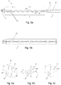
- Figure 3 shows a drilling tool 1 according to a further embodiment.
- the reference numerals correspond Figure 1 .
- chamfers 10 are formed here on the webs along the route SpErw1.
- Guide chamfers 10 bring about a favorable guidance and support of the drilling tool 1 with low friction.
- the guide chamfers 10 are realized here by a recess on the cutting back 8, so that there is one guide chamfer 10 on the secondary cutting edge 11 per web 7 and another guide chamfer 10 on the side of the web 7 facing away from the direction of rotation R.
- the chip space widening 9 only begins after the section of the cutting section 3 on which the guide chamfers 10 are formed.
- the support by the guide chamfers 10 thus takes place over a larger angular range in comparison to guide chamfers 10 on a web 7 with a reduced web width b.
- Figure 4a shows a cross section of the drilling tool 1 in the region of the line SpErw1, on which the guide chamfers 10 are formed. It can be seen that the guide chamfers 10 are formed by a recess on the cutting back 8. The guide chamfers 10 are distributed at angular intervals of approximately 90 ° along the circumference of the drilling tool 1, whereby uniform support and guidance of the drilling tool 1 is achieved.
- the length of the path SpErw1, on which the guide chamfers 10 are formed is 3.5 x the drill diameter D in the present example.
- FIG 4b shows a section in section SpErw2, in which the chip space extension 9 begins.
- the chip space widening 9 is designed such that the web width b on a web 7 is reduced on the side facing away from the direction of rotation 7.
- the secondary cutting edge 11 remains unaffected by the chip space extension 9.
- the web 7 is therefore not reduced in its web width b from both sides.
- the web width b is reduced along the section SpErw2 from the original value b1 to the value b2. In the SpErw2 section, no guide chamfers are formed on the webs 7.
- Figure 4c shows a cross section of the drilling tool 1 in the region of the third section SpErw3.
- the web width b has a difference from the situation in FIG Figure 4a reduced to the value b2.
- FIG. 5a shows a drilling tool 1 according to a further embodiment. Coolant channels 12 running inside the drilling tool 1 are provided here. Guide chamfers 10 are formed in the area of the line 14.
- a coolant / lubricant can be conveyed to the drill face 4 through the coolant channels 12.
- the coolant channels 12 are twisted at a spiral angle to the longitudinal axis L.
- the function of the inventive drilling tool 1 is particularly advantageously supported by the coolant / lubricant which can be conveyed to the drill face 4 via coolant channels 12, since the coolant / lubricant further promotes the removal of chips.
- a distributor chamber 13 for the coolant / lubricant is provided in the shaft section 2. Via the distribution chamber 13, the coolant / lubricant can advantageously be clamped (not shown) to the Drilling tool 1 are handed over.
- This embodiment with a distributor chamber 13 is particularly interesting for particularly long tools and / or tools with small diameters in order to keep a flow resistance for the coolant / lubricant low.
- Figure 5b shows a detail of a drilling tool 1 according to a further embodiment. Here is in contrast to the embodiment of
- FIGS 6a to 6c show cross sections of drilling tools 1 with coolant channels 12.
- Figure 6a shows a cross section of the drilling tool 1 in the region of the line 14 along which the guide chamfers 10 are formed.
- the internal coolant channels 12 can be seen in the cross section of the drilling tool 1.
- the coolant channels 12 have a circular cross section.
- Figure 6b shows a section in section SpErw2, in which the chip space extension 9 begins.
- the chip space widening 9 is designed such that the web width b on a web 7 is reduced on the side facing away from the direction of rotation 7.
- coolant channels 12 are arranged such that there is a sufficient distance from the chip space widening 9 in order not to weaken the web 7 in the area of the coolant channels 12.
- Figure 6c shows a cross section of the drilling tool 1 in the region of the third section SpErw3.
- coolant channels 12 are independent of the presence of guide chamfers 10. Drilling tools 1 with coolant channels 12 without guide chamfers 10 can therefore exist.
- Figure 7 shows a photograph of a drilling tool 1 according to the invention.
- the chip space widening 9 is emphasized, which is formed at the expense of the webs 7 on the side facing away from the direction of rotation R.
- Grinding grooves are indicated by arrows, which are generated by an engagement of a rotating grinding tool (not shown), in particular a profile grinding wheel.
- the chip space widening 9 produced by the engagement of the grinding tool has a main direction of extension X, which extends at an angle ⁇ to the longitudinal axis L of the drill, the angle ⁇ being greater than the helix angle ⁇ of the corresponding flute 5.
- the chip space extension 9 is preferably produced by an engagement of the grinding tool such that a plane of rotation of the grinding tool is set at an angle ⁇ to the longitudinal axis L of the drilling tool 1 and then the flute 5 is moved relative to the drilling tool 1, so that webs 7 on the Direction of rotation R side are partially removed.
- Figure 8 shows a further photograph of a drilling tool 1 according to the invention. It can be seen that in the region of the chip space widening 9 a web width b2 of the web 7 is reduced compared to a region in the longitudinal direction in front of it with a web width b1.
Landscapes
- Engineering & Computer Science (AREA)
- Mechanical Engineering (AREA)
- Drilling Tools (AREA)
Priority Applications (6)
| Application Number | Priority Date | Filing Date | Title |
|---|---|---|---|
| EP18212364.6A EP3666433B1 (fr) | 2018-12-13 | 2018-12-13 | Outil de perçage |
| CN201980079646.4A CN113165088B (zh) | 2018-12-13 | 2019-11-27 | 钻具 |
| PCT/EP2019/082747 WO2020120138A1 (fr) | 2018-12-13 | 2019-11-27 | Outil de perçage |
| US17/413,644 US12076796B2 (en) | 2018-12-13 | 2019-11-27 | Drilling tool |
| JP2021533210A JP2022512198A (ja) | 2018-12-13 | 2019-11-27 | 穴あけ工具 |
| KR1020217015147A KR102708822B1 (ko) | 2018-12-13 | 2019-11-27 | 드릴링 공구 |
Applications Claiming Priority (1)
| Application Number | Priority Date | Filing Date | Title |
|---|---|---|---|
| EP18212364.6A EP3666433B1 (fr) | 2018-12-13 | 2018-12-13 | Outil de perçage |
Publications (3)
| Publication Number | Publication Date |
|---|---|
| EP3666433A1 true EP3666433A1 (fr) | 2020-06-17 |
| EP3666433B1 EP3666433B1 (fr) | 2023-09-27 |
| EP3666433C0 EP3666433C0 (fr) | 2023-09-27 |
Family
ID=64665452
Family Applications (1)
| Application Number | Title | Priority Date | Filing Date |
|---|---|---|---|
| EP18212364.6A Active EP3666433B1 (fr) | 2018-12-13 | 2018-12-13 | Outil de perçage |
Country Status (6)
| Country | Link |
|---|---|
| US (1) | US12076796B2 (fr) |
| EP (1) | EP3666433B1 (fr) |
| JP (1) | JP2022512198A (fr) |
| KR (1) | KR102708822B1 (fr) |
| CN (1) | CN113165088B (fr) |
| WO (1) | WO2020120138A1 (fr) |
Citations (4)
| Publication number | Priority date | Publication date | Assignee | Title |
|---|---|---|---|---|
| WO1995004624A1 (fr) * | 1993-08-06 | 1995-02-16 | Kennametal Hertel Ag Werkzeuge + Hartstoffe | Foret helicoïdal |
| DE69209034T2 (de) * | 1991-12-16 | 1996-07-25 | Sandvik Ab | Bohrer |
| DE69709966T2 (de) * | 1996-02-14 | 2002-10-02 | Sumitomo Electric Industries, Ltd. | Bohrer |
| EP1396303A2 (fr) * | 2002-09-03 | 2004-03-10 | Mitsubishi Materials Corporation | Foret et procédé pour sa production |
Family Cites Families (18)
| Publication number | Priority date | Publication date | Assignee | Title |
|---|---|---|---|---|
| US5350261A (en) * | 1992-03-12 | 1994-09-27 | Mitsubishi Materials Corporation | Twist drill |
| CZ292324B6 (cs) * | 1996-02-29 | 2003-09-17 | Komet Präzisionswerkzeuge Robert Breuning Gmbh | Vrtací nástroj pro obráběcí stroje a způsob jeho výroby |
| US6315504B1 (en) * | 1998-10-27 | 2001-11-13 | Nachi-Fujikoshi Corporation | Twist Drill |
| JP2004090196A (ja) * | 2002-09-03 | 2004-03-25 | Mitsubishi Materials Corp | ドリルおよびその製造方法 |
| JP3720010B2 (ja) * | 2002-10-02 | 2005-11-24 | オーエスジー株式会社 | 深穴加工用ドリル |
| EP1512476B1 (fr) * | 2003-09-08 | 2013-10-09 | Black & Decker Inc. | Foret à auto-centrage avec pointe pilote |
| JP2006326752A (ja) * | 2005-05-26 | 2006-12-07 | Mitsubishi Materials Corp | ドリル |
| SE531188C2 (sv) * | 2007-05-29 | 2009-01-13 | Sandvik Intellectual Property | Borrkropp för spånavskiljande bearbetning |
| DE102008023856A1 (de) * | 2008-05-16 | 2009-11-19 | Gühring Ohg | Mehrschneidiges Vollhartmetall-Bohrwerkzeug |
| DE102008027705B4 (de) * | 2008-06-11 | 2024-06-13 | Gühring KG | Mehrschneidiges Bohrwerkzeug zur Zerspanung von schwer zerspanbaren, insbesondere langspanenden Werkstoffen |
| DE102009025223A1 (de) * | 2009-06-08 | 2010-12-09 | MAPAL Fabrik für Präzisionswerkzeuge Dr. Kress KG | Bohrer |
| DE102010017163A1 (de) * | 2010-05-31 | 2011-12-01 | Gühring Ohg | Bohrwerkzeug |
| JP5368384B2 (ja) * | 2010-06-30 | 2013-12-18 | オーエスジー株式会社 | 深穴加工用ドリル |
| WO2012068641A1 (fr) * | 2010-11-26 | 2012-05-31 | Cpl Holdings Pty Ltd | Trépan |
| IL211236A0 (en) * | 2011-02-15 | 2011-04-28 | Vladimir Volokh | Rotary cutter |
| DE102012012479A1 (de) * | 2012-03-26 | 2013-09-26 | MAPAL Fabrik für Präzisionswerkzeuge Dr. Kress KG | Bohrer |
| WO2017179689A1 (fr) * | 2016-04-15 | 2017-10-19 | 三菱日立ツール株式会社 | Trépan à petit diamètre |
| JP6690456B2 (ja) * | 2016-07-29 | 2020-04-28 | 三菱マテリアル株式会社 | 刃先交換式ドリルのドリル本体、及び刃先交換式ドリル |
-
2018
- 2018-12-13 EP EP18212364.6A patent/EP3666433B1/fr active Active
-
2019
- 2019-11-27 US US17/413,644 patent/US12076796B2/en active Active
- 2019-11-27 CN CN201980079646.4A patent/CN113165088B/zh active Active
- 2019-11-27 JP JP2021533210A patent/JP2022512198A/ja active Pending
- 2019-11-27 WO PCT/EP2019/082747 patent/WO2020120138A1/fr not_active Ceased
- 2019-11-27 KR KR1020217015147A patent/KR102708822B1/ko active Active
Patent Citations (4)
| Publication number | Priority date | Publication date | Assignee | Title |
|---|---|---|---|---|
| DE69209034T2 (de) * | 1991-12-16 | 1996-07-25 | Sandvik Ab | Bohrer |
| WO1995004624A1 (fr) * | 1993-08-06 | 1995-02-16 | Kennametal Hertel Ag Werkzeuge + Hartstoffe | Foret helicoïdal |
| DE69709966T2 (de) * | 1996-02-14 | 2002-10-02 | Sumitomo Electric Industries, Ltd. | Bohrer |
| EP1396303A2 (fr) * | 2002-09-03 | 2004-03-10 | Mitsubishi Materials Corporation | Foret et procédé pour sa production |
Also Published As
| Publication number | Publication date |
|---|---|
| KR102708822B1 (ko) | 2024-09-23 |
| KR20210097701A (ko) | 2021-08-09 |
| CN113165088A (zh) | 2021-07-23 |
| CN113165088B (zh) | 2024-11-29 |
| EP3666433B1 (fr) | 2023-09-27 |
| US20220072629A1 (en) | 2022-03-10 |
| US12076796B2 (en) | 2024-09-03 |
| EP3666433C0 (fr) | 2023-09-27 |
| WO2020120138A1 (fr) | 2020-06-18 |
| JP2022512198A (ja) | 2022-02-02 |
Similar Documents
| Publication | Publication Date | Title |
|---|---|---|
| EP2237913B9 (fr) | Outil de perçage et pointe correspondante | |
| DE60131158T2 (de) | Bohrer mit verbesserter schneideinsatzformation | |
| EP2185306B1 (fr) | Outil de perçage pour machines-outils ainsi que procédé pour sa fabrication | |
| EP1294515B1 (fr) | Meche pour un foret helicoidal et procede pour la production d'une goujure dans la zone d'une meche pour un foret helicoidal | |
| EP1616652B1 (fr) | Outil pour le finissage sans enlèvement de copeaux d'un taraudage préformé, procédé de fabrication de cet outil et procéde de réalisation d'un taraudage | |
| DE4307553B4 (de) | Spiralbohrer | |
| DE69209034T2 (de) | Bohrer | |
| DE4339032C2 (de) | Werkzeug zum Ausschneiden von Scheiben aus einem Werkstück | |
| EP1846186B1 (fr) | Foret long | |
| DE2917811A1 (de) | Gewindeformende schraube | |
| DE102010006796A1 (de) | Verfahren zur Herstellung eines Bohrers, sowie Bohrer | |
| DE102019102726A1 (de) | Bohrwerkzeug und Verfahren zur Erzeugung einer Bohrung | |
| DE102016200404B4 (de) | Verfahren zur Herstellung eines Rotationswerkzeugs und Rotationswerkzeug | |
| DE2064024A1 (de) | Bohrer und Verfahren zum Herstellen des Bohrers | |
| WO2011023428A1 (fr) | Outil | |
| DE10009732A1 (de) | Gesteinsbohrer | |
| WO2021121468A1 (fr) | Foret hélicoïdal ayant une pointe de coupe munie d'une structure étagée | |
| AT16076U1 (de) | Werkzeugkörper sowie ein Verfahren zur Herstellung | |
| WO2008080748A1 (fr) | Foret de forage de trous profonds doté d'une bague de soutien et procédé pour sa fabrication | |
| WO2018065550A1 (fr) | Outil de perçage métallique | |
| DE102008052743A1 (de) | Werkzeug zur spanenden Bearbeitung | |
| DE102017208039B4 (de) | Verfahren zur Herstellung eines Rotationswerkzeugs und Rotationswerkzeug | |
| EP3666433B1 (fr) | Outil de perçage | |
| DE10202954B4 (de) | Verfahren zur Herstellung eines stabförmigen Bohrers aus Hartmetall oder Keramik | |
| DE20212852U1 (de) | Mehrstufen-Bohrwerkzeug |
Legal Events
| Date | Code | Title | Description |
|---|---|---|---|
| PUAI | Public reference made under article 153(3) epc to a published international application that has entered the european phase |
Free format text: ORIGINAL CODE: 0009012 |
|
| STAA | Information on the status of an ep patent application or granted ep patent |
Free format text: STATUS: THE APPLICATION HAS BEEN PUBLISHED |
|
| AK | Designated contracting states |
Kind code of ref document: A1 Designated state(s): AL AT BE BG CH CY CZ DE DK EE ES FI FR GB GR HR HU IE IS IT LI LT LU LV MC MK MT NL NO PL PT RO RS SE SI SK SM TR |
|
| AX | Request for extension of the european patent |
Extension state: BA ME |
|
| STAA | Information on the status of an ep patent application or granted ep patent |
Free format text: STATUS: REQUEST FOR EXAMINATION WAS MADE |
|
| 17P | Request for examination filed |
Effective date: 20201209 |
|
| RBV | Designated contracting states (corrected) |
Designated state(s): AL AT BE BG CH CY CZ DE DK EE ES FI FR GB GR HR HU IE IS IT LI LT LU LV MC MK MT NL NO PL PT RO RS SE SI SK SM TR |
|
| RIC1 | Information provided on ipc code assigned before grant |
Ipc: B23B 51/06 20060101ALN20230509BHEP Ipc: B24B 19/02 20060101ALI20230509BHEP Ipc: B24B 19/04 20060101ALI20230509BHEP Ipc: B23B 51/02 20060101AFI20230509BHEP |
|
| GRAP | Despatch of communication of intention to grant a patent |
Free format text: ORIGINAL CODE: EPIDOSNIGR1 |
|
| STAA | Information on the status of an ep patent application or granted ep patent |
Free format text: STATUS: GRANT OF PATENT IS INTENDED |
|
| INTG | Intention to grant announced |
Effective date: 20230620 |
|
| GRAS | Grant fee paid |
Free format text: ORIGINAL CODE: EPIDOSNIGR3 |
|
| GRAA | (expected) grant |
Free format text: ORIGINAL CODE: 0009210 |
|
| STAA | Information on the status of an ep patent application or granted ep patent |
Free format text: STATUS: THE PATENT HAS BEEN GRANTED |
|
| AK | Designated contracting states |
Kind code of ref document: B1 Designated state(s): AL AT BE BG CH CY CZ DE DK EE ES FI FR GB GR HR HU IE IS IT LI LT LU LV MC MK MT NL NO PL PT RO RS SE SI SK SM TR |
|
| REG | Reference to a national code |
Ref country code: GB Ref legal event code: FG4D Free format text: NOT ENGLISH |
|
| REG | Reference to a national code |
Ref country code: CH Ref legal event code: EP |
|
| REG | Reference to a national code |
Ref country code: DE Ref legal event code: R096 Ref document number: 502018013321 Country of ref document: DE |
|
| REG | Reference to a national code |
Ref country code: IE Ref legal event code: FG4D Free format text: LANGUAGE OF EP DOCUMENT: GERMAN |
|
| U01 | Request for unitary effect filed |
Effective date: 20231026 |
|
| U07 | Unitary effect registered |
Designated state(s): AT BE BG DE DK EE FI FR IT LT LU LV MT NL PT SE SI Effective date: 20231102 |
|
| PG25 | Lapsed in a contracting state [announced via postgrant information from national office to epo] |
Ref country code: GR Free format text: LAPSE BECAUSE OF FAILURE TO SUBMIT A TRANSLATION OF THE DESCRIPTION OR TO PAY THE FEE WITHIN THE PRESCRIBED TIME-LIMIT Effective date: 20231228 |
|
| PG25 | Lapsed in a contracting state [announced via postgrant information from national office to epo] |
Ref country code: RS Free format text: LAPSE BECAUSE OF FAILURE TO SUBMIT A TRANSLATION OF THE DESCRIPTION OR TO PAY THE FEE WITHIN THE PRESCRIBED TIME-LIMIT Effective date: 20230927 Ref country code: NO Free format text: LAPSE BECAUSE OF FAILURE TO SUBMIT A TRANSLATION OF THE DESCRIPTION OR TO PAY THE FEE WITHIN THE PRESCRIBED TIME-LIMIT Effective date: 20231227 Ref country code: HR Free format text: LAPSE BECAUSE OF FAILURE TO SUBMIT A TRANSLATION OF THE DESCRIPTION OR TO PAY THE FEE WITHIN THE PRESCRIBED TIME-LIMIT Effective date: 20230927 Ref country code: GR Free format text: LAPSE BECAUSE OF FAILURE TO SUBMIT A TRANSLATION OF THE DESCRIPTION OR TO PAY THE FEE WITHIN THE PRESCRIBED TIME-LIMIT Effective date: 20231228 |
|
| U20 | Renewal fee for the european patent with unitary effect paid |
Year of fee payment: 6 Effective date: 20240124 |
|
| PG25 | Lapsed in a contracting state [announced via postgrant information from national office to epo] |
Ref country code: IS Free format text: LAPSE BECAUSE OF FAILURE TO SUBMIT A TRANSLATION OF THE DESCRIPTION OR TO PAY THE FEE WITHIN THE PRESCRIBED TIME-LIMIT Effective date: 20240127 |
|
| PG25 | Lapsed in a contracting state [announced via postgrant information from national office to epo] |
Ref country code: ES Free format text: LAPSE BECAUSE OF FAILURE TO SUBMIT A TRANSLATION OF THE DESCRIPTION OR TO PAY THE FEE WITHIN THE PRESCRIBED TIME-LIMIT Effective date: 20230927 |
|
| PG25 | Lapsed in a contracting state [announced via postgrant information from national office to epo] |
Ref country code: SM Free format text: LAPSE BECAUSE OF FAILURE TO SUBMIT A TRANSLATION OF THE DESCRIPTION OR TO PAY THE FEE WITHIN THE PRESCRIBED TIME-LIMIT Effective date: 20230927 Ref country code: RO Free format text: LAPSE BECAUSE OF FAILURE TO SUBMIT A TRANSLATION OF THE DESCRIPTION OR TO PAY THE FEE WITHIN THE PRESCRIBED TIME-LIMIT Effective date: 20230927 Ref country code: IS Free format text: LAPSE BECAUSE OF FAILURE TO SUBMIT A TRANSLATION OF THE DESCRIPTION OR TO PAY THE FEE WITHIN THE PRESCRIBED TIME-LIMIT Effective date: 20240127 Ref country code: ES Free format text: LAPSE BECAUSE OF FAILURE TO SUBMIT A TRANSLATION OF THE DESCRIPTION OR TO PAY THE FEE WITHIN THE PRESCRIBED TIME-LIMIT Effective date: 20230927 Ref country code: CZ Free format text: LAPSE BECAUSE OF FAILURE TO SUBMIT A TRANSLATION OF THE DESCRIPTION OR TO PAY THE FEE WITHIN THE PRESCRIBED TIME-LIMIT Effective date: 20230927 Ref country code: SK Free format text: LAPSE BECAUSE OF FAILURE TO SUBMIT A TRANSLATION OF THE DESCRIPTION OR TO PAY THE FEE WITHIN THE PRESCRIBED TIME-LIMIT Effective date: 20230927 |
|
| PG25 | Lapsed in a contracting state [announced via postgrant information from national office to epo] |
Ref country code: PL Free format text: LAPSE BECAUSE OF FAILURE TO SUBMIT A TRANSLATION OF THE DESCRIPTION OR TO PAY THE FEE WITHIN THE PRESCRIBED TIME-LIMIT Effective date: 20230927 |
|
| REG | Reference to a national code |
Ref country code: DE Ref legal event code: R097 Ref document number: 502018013321 Country of ref document: DE |
|
| REG | Reference to a national code |
Ref country code: CH Ref legal event code: PL |
|
| PLBE | No opposition filed within time limit |
Free format text: ORIGINAL CODE: 0009261 |
|
| STAA | Information on the status of an ep patent application or granted ep patent |
Free format text: STATUS: NO OPPOSITION FILED WITHIN TIME LIMIT |
|
| PG25 | Lapsed in a contracting state [announced via postgrant information from national office to epo] |
Ref country code: MC Free format text: LAPSE BECAUSE OF FAILURE TO SUBMIT A TRANSLATION OF THE DESCRIPTION OR TO PAY THE FEE WITHIN THE PRESCRIBED TIME-LIMIT Effective date: 20230927 |
|
| GBPC | Gb: european patent ceased through non-payment of renewal fee |
Effective date: 20231227 |
|
| PG25 | Lapsed in a contracting state [announced via postgrant information from national office to epo] |
Ref country code: MC Free format text: LAPSE BECAUSE OF FAILURE TO SUBMIT A TRANSLATION OF THE DESCRIPTION OR TO PAY THE FEE WITHIN THE PRESCRIBED TIME-LIMIT Effective date: 20230927 |
|
| 26N | No opposition filed |
Effective date: 20240628 |
|
| REG | Reference to a national code |
Ref country code: IE Ref legal event code: MM4A |
|
| PG25 | Lapsed in a contracting state [announced via postgrant information from national office to epo] |
Ref country code: IE Free format text: LAPSE BECAUSE OF NON-PAYMENT OF DUE FEES Effective date: 20231213 |
|
| PG25 | Lapsed in a contracting state [announced via postgrant information from national office to epo] |
Ref country code: GB Free format text: LAPSE BECAUSE OF NON-PAYMENT OF DUE FEES Effective date: 20231227 |
|
| PG25 | Lapsed in a contracting state [announced via postgrant information from national office to epo] |
Ref country code: CH Free format text: LAPSE BECAUSE OF NON-PAYMENT OF DUE FEES Effective date: 20231231 |
|
| PG25 | Lapsed in a contracting state [announced via postgrant information from national office to epo] |
Ref country code: IE Free format text: LAPSE BECAUSE OF NON-PAYMENT OF DUE FEES Effective date: 20231213 Ref country code: GB Free format text: LAPSE BECAUSE OF NON-PAYMENT OF DUE FEES Effective date: 20231227 Ref country code: CH Free format text: LAPSE BECAUSE OF NON-PAYMENT OF DUE FEES Effective date: 20231231 |
|
| U20 | Renewal fee for the european patent with unitary effect paid |
Year of fee payment: 7 Effective date: 20241227 |
|
| PG25 | Lapsed in a contracting state [announced via postgrant information from national office to epo] |
Ref country code: CY Free format text: LAPSE BECAUSE OF FAILURE TO SUBMIT A TRANSLATION OF THE DESCRIPTION OR TO PAY THE FEE WITHIN THE PRESCRIBED TIME-LIMIT; INVALID AB INITIO Effective date: 20181213 |
|
| PG25 | Lapsed in a contracting state [announced via postgrant information from national office to epo] |
Ref country code: HU Free format text: LAPSE BECAUSE OF FAILURE TO SUBMIT A TRANSLATION OF THE DESCRIPTION OR TO PAY THE FEE WITHIN THE PRESCRIBED TIME-LIMIT; INVALID AB INITIO Effective date: 20181213 |
|
| PG25 | Lapsed in a contracting state [announced via postgrant information from national office to epo] |
Ref country code: TR Free format text: LAPSE BECAUSE OF FAILURE TO SUBMIT A TRANSLATION OF THE DESCRIPTION OR TO PAY THE FEE WITHIN THE PRESCRIBED TIME-LIMIT Effective date: 20230927 |
|
| U20 | Renewal fee for the european patent with unitary effect paid |
Year of fee payment: 8 Effective date: 20251230 |