EP3666447A1 - Procédé de fabrication d'un outil industriel, tel qu'un rouleau d'enclume - Google Patents
Procédé de fabrication d'un outil industriel, tel qu'un rouleau d'enclume Download PDFInfo
- Publication number
- EP3666447A1 EP3666447A1 EP19207404.5A EP19207404A EP3666447A1 EP 3666447 A1 EP3666447 A1 EP 3666447A1 EP 19207404 A EP19207404 A EP 19207404A EP 3666447 A1 EP3666447 A1 EP 3666447A1
- Authority
- EP
- European Patent Office
- Prior art keywords
- powder material
- metallic
- protrusions
- metallic powder
- circumferential surface
- Prior art date
- Legal status (The legal status is an assumption and is not a legal conclusion. Google has not performed a legal analysis and makes no representation as to the accuracy of the status listed.)
- Pending
Links
Images


Classifications
-
- B—PERFORMING OPERATIONS; TRANSPORTING
- B23—MACHINE TOOLS; METAL-WORKING NOT OTHERWISE PROVIDED FOR
- B23K—SOLDERING OR UNSOLDERING; WELDING; CLADDING OR PLATING BY SOLDERING OR WELDING; CUTTING BY APPLYING HEAT LOCALLY, e.g. FLAME CUTTING; WORKING BY LASER BEAM
- B23K26/00—Working by laser beam, e.g. welding, cutting or boring
- B23K26/02—Positioning or observing the workpiece, e.g. with respect to the point of impact; Aligning, aiming or focusing the laser beam
- B23K26/06—Shaping the laser beam, e.g. by masks or multi-focusing
- B23K26/062—Shaping the laser beam, e.g. by masks or multi-focusing by direct control of the laser beam
- B23K26/0622—Shaping the laser beam, e.g. by masks or multi-focusing by direct control of the laser beam by shaping pulses
-
- B—PERFORMING OPERATIONS; TRANSPORTING
- B22—CASTING; POWDER METALLURGY
- B22F—WORKING METALLIC POWDER; MANUFACTURE OF ARTICLES FROM METALLIC POWDER; MAKING METALLIC POWDER; APPARATUS OR DEVICES SPECIALLY ADAPTED FOR METALLIC POWDER
- B22F10/00—Additive manufacturing of workpieces or articles from metallic powder
- B22F10/20—Direct sintering or melting
- B22F10/25—Direct deposition of metal particles, e.g. direct metal deposition [DMD] or laser engineered net shaping [LENS]
-
- B—PERFORMING OPERATIONS; TRANSPORTING
- B22—CASTING; POWDER METALLURGY
- B22F—WORKING METALLIC POWDER; MANUFACTURE OF ARTICLES FROM METALLIC POWDER; MAKING METALLIC POWDER; APPARATUS OR DEVICES SPECIALLY ADAPTED FOR METALLIC POWDER
- B22F12/00—Apparatus or devices specially adapted for additive manufacturing; Auxiliary means for additive manufacturing; Combinations of additive manufacturing apparatus or devices with other processing apparatus or devices
- B22F12/40—Radiation means
- B22F12/41—Radiation means characterised by the type, e.g. laser or electron beam
- B22F12/43—Radiation means characterised by the type, e.g. laser or electron beam pulsed; frequency modulated
-
- B—PERFORMING OPERATIONS; TRANSPORTING
- B23—MACHINE TOOLS; METAL-WORKING NOT OTHERWISE PROVIDED FOR
- B23K—SOLDERING OR UNSOLDERING; WELDING; CLADDING OR PLATING BY SOLDERING OR WELDING; CUTTING BY APPLYING HEAT LOCALLY, e.g. FLAME CUTTING; WORKING BY LASER BEAM
- B23K26/00—Working by laser beam, e.g. welding, cutting or boring
- B23K26/14—Working by laser beam, e.g. welding, cutting or boring using a fluid stream, e.g. a jet of gas, in conjunction with the laser beam; Nozzles therefor
- B23K26/144—Working by laser beam, e.g. welding, cutting or boring using a fluid stream, e.g. a jet of gas, in conjunction with the laser beam; Nozzles therefor the fluid stream containing particles, e.g. powder
-
- B—PERFORMING OPERATIONS; TRANSPORTING
- B23—MACHINE TOOLS; METAL-WORKING NOT OTHERWISE PROVIDED FOR
- B23K—SOLDERING OR UNSOLDERING; WELDING; CLADDING OR PLATING BY SOLDERING OR WELDING; CUTTING BY APPLYING HEAT LOCALLY, e.g. FLAME CUTTING; WORKING BY LASER BEAM
- B23K26/00—Working by laser beam, e.g. welding, cutting or boring
- B23K26/14—Working by laser beam, e.g. welding, cutting or boring using a fluid stream, e.g. a jet of gas, in conjunction with the laser beam; Nozzles therefor
- B23K26/1462—Nozzles; Features related to nozzles
- B23K26/1464—Supply to, or discharge from, nozzles of media, e.g. gas, powder, wire
- B23K26/1476—Features inside the nozzle for feeding the fluid stream through the nozzle
-
- B—PERFORMING OPERATIONS; TRANSPORTING
- B23—MACHINE TOOLS; METAL-WORKING NOT OTHERWISE PROVIDED FOR
- B23K—SOLDERING OR UNSOLDERING; WELDING; CLADDING OR PLATING BY SOLDERING OR WELDING; CUTTING BY APPLYING HEAT LOCALLY, e.g. FLAME CUTTING; WORKING BY LASER BEAM
- B23K26/00—Working by laser beam, e.g. welding, cutting or boring
- B23K26/34—Laser welding for purposes other than joining
- B23K26/342—Build-up welding
-
- B—PERFORMING OPERATIONS; TRANSPORTING
- B26—HAND CUTTING TOOLS; CUTTING; SEVERING
- B26D—CUTTING; DETAILS COMMON TO MACHINES FOR PERFORATING, PUNCHING, CUTTING-OUT, STAMPING-OUT OR SEVERING
- B26D7/00—Details of apparatus for cutting, cutting-out, stamping-out, punching, perforating, or severing by means other than cutting
- B26D7/20—Cutting beds
- B26D7/204—Anvil rollers
-
- B—PERFORMING OPERATIONS; TRANSPORTING
- B26—HAND CUTTING TOOLS; CUTTING; SEVERING
- B26F—PERFORATING; PUNCHING; CUTTING-OUT; STAMPING-OUT; SEVERING BY MEANS OTHER THAN CUTTING
- B26F1/00—Perforating; Punching; Cutting-out; Stamping-out; Apparatus therefor
- B26F1/38—Cutting-out; Stamping-out
- B26F1/384—Cutting-out; Stamping-out using rotating drums
-
- B—PERFORMING OPERATIONS; TRANSPORTING
- B22—CASTING; POWDER METALLURGY
- B22F—WORKING METALLIC POWDER; MANUFACTURE OF ARTICLES FROM METALLIC POWDER; MAKING METALLIC POWDER; APPARATUS OR DEVICES SPECIALLY ADAPTED FOR METALLIC POWDER
- B22F10/00—Additive manufacturing of workpieces or articles from metallic powder
- B22F10/60—Treatment of workpieces or articles after build-up
- B22F10/66—Treatment of workpieces or articles after build-up by mechanical means
-
- B—PERFORMING OPERATIONS; TRANSPORTING
- B22—CASTING; POWDER METALLURGY
- B22F—WORKING METALLIC POWDER; MANUFACTURE OF ARTICLES FROM METALLIC POWDER; MAKING METALLIC POWDER; APPARATUS OR DEVICES SPECIALLY ADAPTED FOR METALLIC POWDER
- B22F2302/00—Metal Compound, non-Metallic compound or non-metal composition of the powder or its coating
- B22F2302/10—Carbide
-
- B—PERFORMING OPERATIONS; TRANSPORTING
- B22—CASTING; POWDER METALLURGY
- B22F—WORKING METALLIC POWDER; MANUFACTURE OF ARTICLES FROM METALLIC POWDER; MAKING METALLIC POWDER; APPARATUS OR DEVICES SPECIALLY ADAPTED FOR METALLIC POWDER
- B22F2304/00—Physical aspects of the powder
- B22F2304/10—Micron size particles, i.e. above 1 micrometer up to 500 micrometer
-
- B—PERFORMING OPERATIONS; TRANSPORTING
- B23—MACHINE TOOLS; METAL-WORKING NOT OTHERWISE PROVIDED FOR
- B23K—SOLDERING OR UNSOLDERING; WELDING; CLADDING OR PLATING BY SOLDERING OR WELDING; CUTTING BY APPLYING HEAT LOCALLY, e.g. FLAME CUTTING; WORKING BY LASER BEAM
- B23K2101/00—Articles made by soldering, welding or cutting
- B23K2101/20—Tools
-
- B—PERFORMING OPERATIONS; TRANSPORTING
- B23—MACHINE TOOLS; METAL-WORKING NOT OTHERWISE PROVIDED FOR
- B23K—SOLDERING OR UNSOLDERING; WELDING; CLADDING OR PLATING BY SOLDERING OR WELDING; CUTTING BY APPLYING HEAT LOCALLY, e.g. FLAME CUTTING; WORKING BY LASER BEAM
- B23K2103/00—Materials to be soldered, welded or cut
- B23K2103/50—Inorganic materials other than metals or composite materials
- B23K2103/52—Ceramics
-
- B—PERFORMING OPERATIONS; TRANSPORTING
- B26—HAND CUTTING TOOLS; CUTTING; SEVERING
- B26D—CUTTING; DETAILS COMMON TO MACHINES FOR PERFORATING, PUNCHING, CUTTING-OUT, STAMPING-OUT OR SEVERING
- B26D1/00—Cutting through work characterised by the nature or movement of the cutting member or particular materials not otherwise provided for; Apparatus or machines therefor; Cutting members therefor
- B26D1/0006—Cutting members therefor
- B26D2001/002—Materials or surface treatments therefor, e.g. composite materials
-
- B—PERFORMING OPERATIONS; TRANSPORTING
- B33—ADDITIVE MANUFACTURING TECHNOLOGY
- B33Y—ADDITIVE MANUFACTURING, i.e. MANUFACTURING OF THREE-DIMENSIONAL [3D] OBJECTS BY ADDITIVE DEPOSITION, ADDITIVE AGGLOMERATION OR ADDITIVE LAYERING, e.g. BY 3D PRINTING, STEREOLITHOGRAPHY OR SELECTIVE LASER SINTERING
- B33Y10/00—Processes of additive manufacturing
-
- B—PERFORMING OPERATIONS; TRANSPORTING
- B33—ADDITIVE MANUFACTURING TECHNOLOGY
- B33Y—ADDITIVE MANUFACTURING, i.e. MANUFACTURING OF THREE-DIMENSIONAL [3D] OBJECTS BY ADDITIVE DEPOSITION, ADDITIVE AGGLOMERATION OR ADDITIVE LAYERING, e.g. BY 3D PRINTING, STEREOLITHOGRAPHY OR SELECTIVE LASER SINTERING
- B33Y80/00—Products made by additive manufacturing
-
- Y—GENERAL TAGGING OF NEW TECHNOLOGICAL DEVELOPMENTS; GENERAL TAGGING OF CROSS-SECTIONAL TECHNOLOGIES SPANNING OVER SEVERAL SECTIONS OF THE IPC; TECHNICAL SUBJECTS COVERED BY FORMER USPC CROSS-REFERENCE ART COLLECTIONS [XRACs] AND DIGESTS
- Y02—TECHNOLOGIES OR APPLICATIONS FOR MITIGATION OR ADAPTATION AGAINST CLIMATE CHANGE
- Y02P—CLIMATE CHANGE MITIGATION TECHNOLOGIES IN THE PRODUCTION OR PROCESSING OF GOODS
- Y02P10/00—Technologies related to metal processing
- Y02P10/25—Process efficiency
Definitions
- the present invention relates to a method of manufacturing tools, in particular industrial tools, such as anvil rolls, by adding metal components which are metallurgically combined to form structures, such as protrusions.
- Laser cladding, or laser metal deposition is an additive production process that uses a laser beam to form a pool of melted metal on the surface of a metallic substrate into which metal powder is injected using a gas stream.
- the absorbed metal powder melts and bonds with the base material to produce a deposit on the surface.
- the laser cladding process is typically followed by a post-machining step to bring the added metal structure within required tolerances.
- Post-machining such as milling, grinding and/or spark erosion may be used.
- post-machining adds further expense to the overall process.
- the present invention relates to a method for making an anvil roll, the method comprising the steps of:
- Anvil roll is used herein to refer to any industrial tool comprising an essentially cylindrical form having a pattern or profile on the outer circumferential surface.
- “Absorbent article” is used herein to refer to consumer products whose primary function is to absorb and retain soils and wastes.
- “Diaper” is used herein to refer to an absorbent article generally worn by infants and incontinent persons about the lower torso.
- the term “disposable” is used herein to describe absorbent articles which generally are not intended to be laundered or otherwise restored or reused as an absorbent article (e.g., they are intended to be discarded after a single use and may also be configured to be recycled, composted or otherwise disposed of in an environmentally compatible manner).
- an “elastic,” “elastomer” or “elastomeric” refers to materials exhibiting elastic properties, which include any material that upon application of a force to its relaxed, initial length can stretch or elongate to an elongated length more than 10% greater than its initial length and will substantially recover back to about its initial length upon release of the applied force.
- joind encompasses configurations whereby an element is directly secured to another element by affixing the element directly to the other element, and configurations whereby an element is indirectly secured to another element by affixing the element to intermediate member(s) which in turn are affixed to the other element.
- substrate is used herein to describe a material which is primarily two-dimensional (i.e. in an XY plane) and whose thickness (in a Z direction) is relatively small (i.e. 1/10 or less) in comparison to its length (in an X direction) and width (in a Y direction).
- substrates include a web, layer or layers or fibrous materials, nonwovens, films and foils such as polymeric films or metallic foils. These materials may be used alone or may comprise two or more layers laminated together. As such, a web is a substrate.
- nonwoven refers herein to a material made from continuous (long) filaments (fibers) and/or discontinuous (short) filaments (fibers) by processes such as spunbonding, meltblowing, carding, and the like. Nonwovens do not have a woven or knitted filament pattern.
- machine direction is used herein to refer to the direction of material flow through a process.
- relative placement and movement of material can be described as flowing in the machine direction through a process from upstream in the process to downstream in the process.
- cross direction is used herein to refer to a direction that is generally perpendicular to the machine direction.
- the present disclosure relates to apparatuses and methods for manufacturing absorbent articles, and more particularly to the manufacture of industrial tools such as rotary anvils that may be used in combination with a tool member or an ultrasonic horn to perform various types of manufacturing operations, such as cutting, bonding, and embossing.
- industrial tools such as rotary anvils that may be used in combination with a tool member or an ultrasonic horn to perform various types of manufacturing operations, such as cutting, bonding, and embossing.
- Particular aspects of the present disclosure involve an anvil roll having a cylindrically-shaped outer circumferential surface and being adapted to rotate about a first axis of rotation.
- the anvil roll includes a body formed from a first material, such as a metallic material.
- one or more metallic materials in the form of powder are added to the outer circumferential surface to form raised protrusions.
- the metallic material comprises wear resistant material which preferably is different from the first material of the body, although materials of similar or even identical characteristics may be used.
- wear resistant is used herein to mean resistance against several different failure mechanisms including abrasion, fatigue, chipping/microchipping and yielding.
- the metallurgy of the protrusion may be tailored to balance the requirements of these different types of failure.
- a tool member may be positioned adjacent the anvil roll and adapted to rotate about a second axis of rotation.
- the anvil roll and the tool member rotate in opposite directions such that a nip is formed between raised protrusions on the outer circumferential surface of the anvil roll and the tool member.
- the anvil roll may be positioned adjacent to an ultrasonic horn which may be either a static or a rotary ultrasonic horn.
- the protrusions of metallic material are formed on and fused by applying power from a laser source, to the body as opposed to being separately fabricated and/or fastened thereto, some of the difficulties associated with current anvil roll manufacturing techniques may be alleviated.
- the protrusions of metallic material are defined herein as “conical” or “frustro-conical” or “cylindrical”.
- the cross-section of the protrusions may be of any desired shape such as square, rectangular, oval, elliptical, or preferably circular.
- the height of the protrusions, measured in the direction radially outwards from the outer circumferential surface of the anvil roll is from about 0.1 mm to about 2 mm, and more preferably from about 0.5 mm to about 1 mm.
- the metallic powder material is applied in layers, and the laser is operated by pulsing the laser and by synchronizing the pulses with the application of successive layers of the powder material.
- a pool of molten material is formed in the target area by a pulse of energy from the laser.
- Metallic powder material is fed into the pool of molten material using a high precision nozzle, preferably by a coaxial feeder nozzle.
- the particle size of the powder is smaller than the diameter of the pool of molten material, and smaller than the diameter of the laser beam in order to completely melt the powder material. Incomplete melting of the powder material would lead to undesirable surface roughness.
- the powder flow is preferably controlled by a rapid powder switch such as the switch described in PhotonicsViews journal on-line: “Powder on Demand: Rapid-Powder-Switch", November 23rd 2017, http://www.photonicsviews.com/powder-on-demand-rapid-powder-switch/ .
- the process is repeated starting with a subsequent pulse of energy from the laser which remelts the target area.
- the pulse time is between about 30 and 350 milliseconds.
- the flow of powder and the laser pulse are synchronised so that the projection is built up in layers.
- Powder flow and laser pulses build up the layers. Between successive layers the powder flow is stopped and laser pulse(s) smooth each layer to a high degree of dimensional accuracy.
- protrusions formed using known laser cladding techniques have rough surfaces at the sides of the protrusion caused by the presence of particulate material which has not been melted, or only partly melted, during the laser deposition process
- the protrusions formed by the present invention have smooth side surfaces because all of the particulate material has been melted during the laser deposition process.
- the thickness of successive layers of metallic powder material is preferably less than 0.1 mm, and more preferably from 0.01 to 0.07 mm.
- the volumetric flow rate of the metallic powder material is from 2 to 10 cm 3 /hour. A dimensional accuracy of the tapering sides of the protrusions within a tolerance of 20 micrometers is achievable.
- Such high dimensional accuracy may be desirable because it makes any further machining step to the conical or frustro-conical tapering sides of the protrusions unnecessary.
- a further machining step or steps may be applied the circumferential surface formed by the outer tips of the protrusions 180.
- a process of grinding the outer diameter to fine dimensional tolerance may be performed.
- further refining processes such as polishing, wet blasting, brushing or others may be performed to smoothen the surfaces of the tips which form the working surfaces of the protrusions. It is intended that the invention described herein does not require any further machining steps to the conical or frustro-conical tapering sides of the protrusions to be performed.
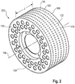
- Figure 1 shows an isometric view of a configuration of an anvil roll 100 having a cylindrically-shaped outer circumferential surface 102 and adapted to rotate about a first axis of rotation 104.
- the anvil roll 100 may extend axially for a length L between a first end 106 and a second end 108.
- the body 110 may be configured as a unitary member made from a first material 118.
- the anvil roll 200 includes one or more holes 122 in the outer circumferential surface 102.
- each hole 122 defines a perimeter 124 in the second portion of the outer circumferential surface 102 and extends radially inward from the outer circumferential surface 102 into the body 110.
- a vacuum source may be in fluid communication with the holes 122. As such, the vacuum source may create vacuum air pressure in the holes 122 during operation to help hold substrates in a desired position on the outer circumferential surface 102 of the anvil roll 200.
- holes 122 are sometimes depicted as being arranged in rows extending axially along the outer circumferential surface 102 of the anvil roll, it is to be appreciated that the holes 122 may be arranged in various ways and may be configured to have the same or different shapes and/or sizes. It is also to be appreciated that various types of one or more vacuum sources and arrangements thereof may be used with the anvil roll 200.
- the first material 118 may be various types of materials, such as various types of metallic materials.
- the first material 118 is selected from the group consisting of: an iron-based alloy, a nickel-based alloy, an aluminum-based alloy, and a titanium-based alloy.
- the iron-based alloy is selected from the group consisting of: stainless steel and tool steel.
- the first material is a hot-working tool steel or a tool steel, such as for example, X37CrMoVS-1 steel.
- the one or more wear resistant materials 120 may be various types of materials.
- the one or more wear resistant materials 120 may include at least one of: powder-metallurgical steel; titanium carbide, niobium carbide, tantalum carbide, chromium carbide, tungsten carbide, and mixtures thereof.
- the wear resistant material 120 may include a carbide of at least one element of the fourth, the fifth, the sixth and/or the seventh group of the periodic table.
- Carbides from the fourth group may be titanium carbide, zirconium carbide, hafnium carbide or a mixture thereof.
- Carbides from the fifth group may be vanadium carbide, niobium carbide, tantalum carbide or a mixture thereof.
- Carbides from the sixth group may be chromium carbide, molybdenum carbide, tungsten carbide or a mixture thereof.
- Carbides from the seventh group may be manganese carbide, rhenium carbide or a mixture thereof.
- Carbides of several groups can be used individually or as a mixture. In one embodiment, titanium carbide, niobium carbide, tantalum carbide, chromium carbide, tungsten carbide or a mixture thereof is used.
- the carbides may be deposited as a powder comprising particles of several sizes and/or shapes.
- Carbides may be provided in a matrix material, wherein matrix material may comprise nickel, cobalt and/or iron.
- the carbides may be present in the matrix material in an amount of from about 60% to about 80%, in another embodiment in an amount of from about 70% to about 80%, in yet another embodiment in an amount of from about 70% to about 75%.
- the metallic materials are added in the form of powder.
- the average diameter of the metallic powder material is less than about 60 micrometers, and more preferably from about 20 to about 50 micrometers.
- the first material 118 may be formed into a generally cylindrically-shaped forging, such as shown in Figure 1 .
- the forging may be machined or otherwise worked to form the body 110.
- the forging may be worked or machined into the body 110 so as to include various features, such as holes 122, such as shown in Figure 2 .
- Holes in the body may extend radially inward from the outer circumferential surface, wherein the holes are in fluid communication with a vacuum pressure source.
- anvils described herein may include vacuum, it is appreciated that anvils herein may be configured without vacuum.
- one or more metallic materials 120 are fused to the body 110, such as shown in Figures 3A and 3B .
- the one or more metallic materials are fused onto the outer circumferential surface of the body to form a plurality of protrusions 180 having a conical or frustro-conical shape comprising generally tapering sides 182, from a broader base at the outer circumferential surface 102 tapering outwardly towards a narrower tip 185.
- the generally tapering sides 182 may be uniformly tapering between the base and the tip 185, i.e. geometrically defining a part of a cone, or alternatively the generally tapering sides 182 may be non-uniformly tapering between the base and the tip 185 or may not be tapered, e.g. cylindrical.
- One or more metallic materials 120 are fused to the body 110 with a laser cladding process, such as disclosed in U.S. Patent Publication No. 2013/0049438 A1 .
- the first material 118 of the body 110 may be partially melted during deposition of the metallic material 120.
- a metallurgic bond may be created between the metallic material 120 and the first material 118 of the body 110.
- a "metallurgical bond” means that the metallic material is fused to the first material of the body such that the microstructure of the first material may be intimately linked to the microstructure of the metallic material.
- metallurgic bonds may be also created between the different wear resistant materials.
- the metallic material may include multiple layers of material, such as layers of different material, that are applied to the body 110, such as disclosed in U.S. Patent Publication No. 2013/0049438 A1 .
- the metallic material may include a first layer, a second layer, and a third layer, wherein the first layer may be referred to as a bonding layer, the second layer may be referred to as a bearing layer, and the third layer may be referred to as a wear resistant layer.
- the bonding layer may be applied to the body 110; the bearing layer may be applied to the bonding layer; and the wear resistant layer may be applied to the bearing layer.
- the first layer or bonding layer may provide a metallurgical bond to the body 110 when applied by a laser cladding process.
- the bonding layer may be a metal alloy that is similar to the first material 118 of the body 110, which in turn, may form little or no brittle phase when mixed with the first material 120.
- the second layer or bearing layer may be configured to provide sufficient strength and stiffness when the wear resistant layer is loaded during operation.
- the second layer or bearing layers may be a metallic alloy that is similar to the bonding layer but contains elements to form solid solutions and/or medium hard phases.
- the third layer or wear resistant layer may be a compound of a matrix in which hard phases, such as for example carbides, borides and/or nitrides, are embedded.
- the matrix may be a metallic alloy which is similar to the bearing layer but also contains elements to form a solid solution and/or medium hard phases, and also be identical with the bearing layer.
- the hard phases may be homogeneously distributed inside the metallic matrix in various amounts.
- the hard phases may also be incorporated as solid particles during the coating process or may precipitate during the solidification process from the melt.
- the laser energy applied to successive layers may be the same energy per layer or may be different energy per layer.
- the laser energy is higher for the base layer(s), nearer to the body of the anvil roll, and the laser energy is lower for the layer(s) further from the anvil roll.
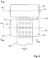
- the anvil roll 100 may be used in combination with a tool member 134, such as shown in Figure 4 , to perform various types of manufacturing operations on an advancing substrate.
- the tool member 134 may include an outer circumferential surface 138 and may be adapted to rotate about a second axis of rotation 140.
- the tool member 134 may be positioned adjacent the anvil roll 100 to define a nip 108.
- the tool member 134 and the anvil roll 100 may be adapted to rotate in opposite directions such that the outer tips of the protrusions 180 may contact the outer circumferential surface 138 of the tool member 134, or, alternatively, a narrow clearance or nip 108 may be formed between the outer tips of the protrusions 180 and the outer circumferential surface 138 of the tool member 134.
- the substrate 136 may advance in the machine direction MD through the nip 108 such that the substrate 136 is impinged upon between the outer circumferential surface 138 of the tool member 134 and the projections 180 of wear resistant material 120.
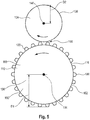
- Figure 5 is a side view of an anvil roll 100 in combination with a tool member 134.
- the anvil roll 100 including projections 180 has a radius, D1
- the tool member has a radius, D2.It is to be appreciated that the tool member 134 may be configured to perform various types of converting operations on the substrate 136, such as for example, cutting, embossing, and bonding, as one or more substrates 136 advance through the nip 108.
- Various examples of tool member configurations that may be used with the anvil rolls 100 herein are described in U.S. Patent Nos.
- the tool member 134 maybe adjacent to the anvil roll 100 and create a nip 142 defined by a minimum distance between the outer circumferential surface 138 of the tool member 134 or cutting roll 146 and the outer circumferential surface 102 of the anvil roll 100.
- Figure 6 is a perspective view of an anvil roll 300 in combination with an ultrasonic horn 330.
- This combination shown in Figure 6 , is a bonding unit used to bond together substrates 236, 238 which are transported through the unit, between the anvil roll 300 and the ultrasonic horn 330, in the machine direction, MD. Vibration of the horn 330 generates heat to melt and bond the substrates 236, 238 together in areas supported by the protrusions 180 on the anvil roll 300.
- the bonds and/or bond regions may have shapes that correspond with and may mirror shapes of the protrusions 180.
- ultrasonic bonding devices may be configured in various ways, such as for example linear or rotary type configurations, and such as disclosed for example in U.S. Patent Nos. 3,113,225 ; 3,562,041 ; 3,733,238 ; 5,110,403 ; 6,036,796 ; 6,508,641 ; and 6,645,330 .
- the pressure applied to the substrates in an ultrasonic bonding unit are lower than the pressure applied in the nip corresponding pressure bonding units described above.
- apparatuses and methods of the present disclosure may be utilized to perform various manufacturing operations on substrates used in the manufacture of absorbent articles.
- substrates may be utilized in absorbent article components such as, for example: backsheets, topsheets, absorbent cores, front and/or back ears, fastener components, and various types of elastic webs and components such as leg elastics, barrier leg cuff elastics, and waist elastics.
- Stellite 6® is a cobalt-chromium alloy designed for wear resistance, supplied by Kennametal Inc. Pulse No. 1 2 3 4 5 6 7 8 9 10 11 12 Laser Power (%) 13 13 9 9 6 6 4 4 3 3 3 3 Pulse length (ms) 100 100 100 50 50 100 50 100 50 100 Powder Amount (%) 6 Amdry 6 S6 6 S6 6 S6 6 S6 6 S6 6 S6
- the powder used for the first layer was Amdry.
- Amdry is a thermal spray powder formed from NiCoCrAlY, supplied by Oerlikon Metco.
- S6 is Stellite 6®. Pulse No. 1 2 3 4 5 6 7 8 9 10 11 12 Laser Power (%) 13 13 9 9 6 6 4 4 3 3 3 3 Pulse length (ms) 100 100 100 50 50 100 50 100 50 100 Powder Amount (%) 6 Amdry 3 CPM 3 CPM 3 CPM 3 CPM 3 CPM 3 CPM 3 CPM 3 CPM
- CPM 420V® is a high wear resistant tool steel, supplied by Zapp Group.
Landscapes
- Engineering & Computer Science (AREA)
- Physics & Mathematics (AREA)
- Optics & Photonics (AREA)
- Mechanical Engineering (AREA)
- Plasma & Fusion (AREA)
- Materials Engineering (AREA)
- Chemical & Material Sciences (AREA)
- Manufacturing & Machinery (AREA)
- Life Sciences & Earth Sciences (AREA)
- Forests & Forestry (AREA)
- Toxicology (AREA)
- General Health & Medical Sciences (AREA)
- Health & Medical Sciences (AREA)
- Laser Beam Processing (AREA)
Priority Applications (1)
| Application Number | Priority Date | Filing Date | Title |
|---|---|---|---|
| US16/689,180 US12440919B2 (en) | 2018-12-10 | 2019-11-20 | Method for making an industrial tool, such as an anvil roll |
Applications Claiming Priority (1)
| Application Number | Priority Date | Filing Date | Title |
|---|---|---|---|
| EP18211337.3A EP3666446A1 (fr) | 2018-12-10 | 2018-12-10 | Procédé de fabrication d'un outil industriel, tel qu'un rouleau d'enclume |
Publications (1)
| Publication Number | Publication Date |
|---|---|
| EP3666447A1 true EP3666447A1 (fr) | 2020-06-17 |
Family
ID=64664159
Family Applications (2)
| Application Number | Title | Priority Date | Filing Date |
|---|---|---|---|
| EP18211337.3A Withdrawn EP3666446A1 (fr) | 2018-12-10 | 2018-12-10 | Procédé de fabrication d'un outil industriel, tel qu'un rouleau d'enclume |
| EP19207404.5A Pending EP3666447A1 (fr) | 2018-12-10 | 2019-11-06 | Procédé de fabrication d'un outil industriel, tel qu'un rouleau d'enclume |
Family Applications Before (1)
| Application Number | Title | Priority Date | Filing Date |
|---|---|---|---|
| EP18211337.3A Withdrawn EP3666446A1 (fr) | 2018-12-10 | 2018-12-10 | Procédé de fabrication d'un outil industriel, tel qu'un rouleau d'enclume |
Country Status (2)
| Country | Link |
|---|---|
| US (1) | US12440919B2 (fr) |
| EP (2) | EP3666446A1 (fr) |
Families Citing this family (1)
| Publication number | Priority date | Publication date | Assignee | Title |
|---|---|---|---|---|
| CN119173235A (zh) | 2022-05-20 | 2024-12-20 | 宝洁公司 | 具有层合粘结图案的吸收制品 |
Citations (30)
| Publication number | Priority date | Publication date | Assignee | Title |
|---|---|---|---|---|
| US3113225A (en) | 1960-06-09 | 1963-12-03 | Cavitron Ultrasonics Inc | Ultrasonic vibration generator |
| US3562041A (en) | 1967-10-26 | 1971-02-09 | Cavitron Corp | Method and apparatus for the ultrasonic joining of materials according to a pattern |
| US3733238A (en) | 1971-12-13 | 1973-05-15 | Crompton & Knowles Corp | Apparatus for vibration welding of sheet materials |
| US4493868A (en) | 1982-12-14 | 1985-01-15 | Kimberly-Clark Corporation | High bulk bonding pattern and method |
| US4854984A (en) | 1987-06-19 | 1989-08-08 | The Procter & Gamble Company | Dynamic mechanical bonding method and apparatus |
| US5110403A (en) | 1990-05-18 | 1992-05-05 | Kimberly-Clark Corporation | High efficiency ultrasonic rotary horn |
| US5620779A (en) | 1993-12-23 | 1997-04-15 | Kimberly-Clark Corporation | Ribbed clothlike nonwoven fabric |
| US5798167A (en) | 1992-05-15 | 1998-08-25 | Kimberly-Clark Worldwide, Inc. | Garment of a durable nonwoven fabric |
| US5855149A (en) * | 1996-11-18 | 1999-01-05 | National Research Council Of Canada | Process for producing a cutting die |
| US6036796A (en) | 1998-06-26 | 2000-03-14 | Branson Electronics | Closed-loop ultrasonic welding method and apparatus |
| US6244148B1 (en) | 1998-07-29 | 2001-06-12 | Aichele Werkzeuge Gmbh | Cutting device |
| US6248195B1 (en) | 1996-11-21 | 2001-06-19 | The Procter & Gamble Company | Thermal joining of webs |
| US6508641B1 (en) | 1998-02-02 | 2003-01-21 | Eduard Kusters Maschinenfabrik Gmbh & Co. Kg | Device for processing a strip of material with ultrasound |
| US6645330B2 (en) | 2002-01-03 | 2003-11-11 | Paragon Trade Brands, Inc. | Method of making disposable absorbent article having graphics using ultrasonic thermal imaging |
| US20060042436A1 (en) * | 2004-08-31 | 2006-03-02 | Michael Closmann | Method and device for producing a cutting or embossing roller by means of laser resurfacing welding |
| EP1635750B1 (fr) | 2003-06-06 | 2009-10-28 | The Procter & Gamble Company | Procedes et appareil pour connecter des matieres, notamment des matieres utilisees dans des articles absorbants |
| US7777094B2 (en) | 2001-03-15 | 2010-08-17 | Daio Paper Corporation | Paper diaper and method for manufacturing extensible sheet used in the diaper |
| US7861756B2 (en) | 2004-04-20 | 2011-01-04 | Curt G. Joa, Inc. | Staggered cutting knife |
| US20120079926A1 (en) | 2010-09-30 | 2012-04-05 | Michael Devin Long | Absorbent Article Substrate Trim Material Removal Process and Apparatus |
| US20130049438A1 (en) | 2011-08-27 | 2013-02-28 | Braun Gmbh | Method For Providing An Abrasion Resistant Cutting Edge And Trimming Device Having Said Cutting Edge |
| US8440043B1 (en) | 2012-03-30 | 2013-05-14 | The Procter & Gamble Company | Absorbent article process and apparatus for intermittently deactivating elastics in elastic laminates |
| US20130213547A1 (en) | 2012-02-22 | 2013-08-22 | Uwe Schneider | Apparatuses and Methods for Bonding Substrates |
| US20130218116A1 (en) | 2012-02-22 | 2013-08-22 | Uwe Schneider | Apparatuses and Methods for Seaming Substrates |
| US20140217058A1 (en) * | 2011-09-23 | 2014-08-07 | Boegli-Gravures S.A. | Method and device for producing a structured surface on a steel embossing roller |
| US20140377513A1 (en) | 2013-06-19 | 2014-12-25 | The Procter & Gamble Company | Bonding Apparatus and Method |
| US20140377506A1 (en) | 2013-06-19 | 2014-12-25 | The Procter & Gamble Company | Bonding Apparatus and Method |
| WO2016012827A1 (fr) * | 2014-07-22 | 2016-01-28 | Sandvik Intellectual Property Ab | Enclume fabriquée par couches additives pour unité de coupe rotative |
| US20170144248A1 (en) * | 2014-03-31 | 2017-05-25 | Mitsubishi Heavy Industries, Ltd. | Three-dimensional deposition device and three-dimensional deposition method |
| EP3305494A1 (fr) * | 2015-05-28 | 2018-04-11 | Think Laboratory Co., Ltd. | Procédé de fabrication de rouleau de gaufrage et rouleau de gaufrage |
| US20190263056A1 (en) * | 2017-06-15 | 2019-08-29 | Sumitomo Electric Sintered Alloy, Ltd. | Method for manufacturing shaped article, and shaped article |
Family Cites Families (8)
| Publication number | Priority date | Publication date | Assignee | Title |
|---|---|---|---|---|
| US5837960A (en) | 1995-08-14 | 1998-11-17 | The Regents Of The University Of California | Laser production of articles from powders |
| US20120132627A1 (en) | 2009-04-28 | 2012-05-31 | Bae Systems Plc | Additive layer fabrication method |
| US20110172137A1 (en) | 2010-01-13 | 2011-07-14 | Francesc Corominas | Method Of Producing A Fabric Softening Composition |
| CN102844420A (zh) | 2010-03-26 | 2012-12-26 | 宝洁公司 | 制备织物软化剂的方法 |
| EP2824169A1 (fr) | 2013-07-12 | 2015-01-14 | The Procter & Gamble Company | Compositions structurées de soin de tissu |
| EP3389899A1 (fr) * | 2015-12-18 | 2018-10-24 | Autotech Engineering, A.I.E. | Renforcement d'éléments structuraux |
| WO2017132099A1 (fr) | 2016-01-25 | 2017-08-03 | The Procter & Gamble Company | Compositions de traitement |
| US11198181B2 (en) * | 2017-03-10 | 2021-12-14 | California Institute Of Technology | Methods for fabricating strain wave gear flexsplines using metal additive manufacturing |
-
2018
- 2018-12-10 EP EP18211337.3A patent/EP3666446A1/fr not_active Withdrawn
-
2019
- 2019-11-06 EP EP19207404.5A patent/EP3666447A1/fr active Pending
- 2019-11-20 US US16/689,180 patent/US12440919B2/en active Active
Patent Citations (30)
| Publication number | Priority date | Publication date | Assignee | Title |
|---|---|---|---|---|
| US3113225A (en) | 1960-06-09 | 1963-12-03 | Cavitron Ultrasonics Inc | Ultrasonic vibration generator |
| US3562041A (en) | 1967-10-26 | 1971-02-09 | Cavitron Corp | Method and apparatus for the ultrasonic joining of materials according to a pattern |
| US3733238A (en) | 1971-12-13 | 1973-05-15 | Crompton & Knowles Corp | Apparatus for vibration welding of sheet materials |
| US4493868A (en) | 1982-12-14 | 1985-01-15 | Kimberly-Clark Corporation | High bulk bonding pattern and method |
| US4854984A (en) | 1987-06-19 | 1989-08-08 | The Procter & Gamble Company | Dynamic mechanical bonding method and apparatus |
| US5110403A (en) | 1990-05-18 | 1992-05-05 | Kimberly-Clark Corporation | High efficiency ultrasonic rotary horn |
| US5798167A (en) | 1992-05-15 | 1998-08-25 | Kimberly-Clark Worldwide, Inc. | Garment of a durable nonwoven fabric |
| US5620779A (en) | 1993-12-23 | 1997-04-15 | Kimberly-Clark Corporation | Ribbed clothlike nonwoven fabric |
| US5855149A (en) * | 1996-11-18 | 1999-01-05 | National Research Council Of Canada | Process for producing a cutting die |
| US6248195B1 (en) | 1996-11-21 | 2001-06-19 | The Procter & Gamble Company | Thermal joining of webs |
| US6508641B1 (en) | 1998-02-02 | 2003-01-21 | Eduard Kusters Maschinenfabrik Gmbh & Co. Kg | Device for processing a strip of material with ultrasound |
| US6036796A (en) | 1998-06-26 | 2000-03-14 | Branson Electronics | Closed-loop ultrasonic welding method and apparatus |
| US6244148B1 (en) | 1998-07-29 | 2001-06-12 | Aichele Werkzeuge Gmbh | Cutting device |
| US7777094B2 (en) | 2001-03-15 | 2010-08-17 | Daio Paper Corporation | Paper diaper and method for manufacturing extensible sheet used in the diaper |
| US6645330B2 (en) | 2002-01-03 | 2003-11-11 | Paragon Trade Brands, Inc. | Method of making disposable absorbent article having graphics using ultrasonic thermal imaging |
| EP1635750B1 (fr) | 2003-06-06 | 2009-10-28 | The Procter & Gamble Company | Procedes et appareil pour connecter des matieres, notamment des matieres utilisees dans des articles absorbants |
| US7861756B2 (en) | 2004-04-20 | 2011-01-04 | Curt G. Joa, Inc. | Staggered cutting knife |
| US20060042436A1 (en) * | 2004-08-31 | 2006-03-02 | Michael Closmann | Method and device for producing a cutting or embossing roller by means of laser resurfacing welding |
| US20120079926A1 (en) | 2010-09-30 | 2012-04-05 | Michael Devin Long | Absorbent Article Substrate Trim Material Removal Process and Apparatus |
| US20130049438A1 (en) | 2011-08-27 | 2013-02-28 | Braun Gmbh | Method For Providing An Abrasion Resistant Cutting Edge And Trimming Device Having Said Cutting Edge |
| US20140217058A1 (en) * | 2011-09-23 | 2014-08-07 | Boegli-Gravures S.A. | Method and device for producing a structured surface on a steel embossing roller |
| US20130213547A1 (en) | 2012-02-22 | 2013-08-22 | Uwe Schneider | Apparatuses and Methods for Bonding Substrates |
| US20130218116A1 (en) | 2012-02-22 | 2013-08-22 | Uwe Schneider | Apparatuses and Methods for Seaming Substrates |
| US8440043B1 (en) | 2012-03-30 | 2013-05-14 | The Procter & Gamble Company | Absorbent article process and apparatus for intermittently deactivating elastics in elastic laminates |
| US20140377513A1 (en) | 2013-06-19 | 2014-12-25 | The Procter & Gamble Company | Bonding Apparatus and Method |
| US20140377506A1 (en) | 2013-06-19 | 2014-12-25 | The Procter & Gamble Company | Bonding Apparatus and Method |
| US20170144248A1 (en) * | 2014-03-31 | 2017-05-25 | Mitsubishi Heavy Industries, Ltd. | Three-dimensional deposition device and three-dimensional deposition method |
| WO2016012827A1 (fr) * | 2014-07-22 | 2016-01-28 | Sandvik Intellectual Property Ab | Enclume fabriquée par couches additives pour unité de coupe rotative |
| EP3305494A1 (fr) * | 2015-05-28 | 2018-04-11 | Think Laboratory Co., Ltd. | Procédé de fabrication de rouleau de gaufrage et rouleau de gaufrage |
| US20190263056A1 (en) * | 2017-06-15 | 2019-08-29 | Sumitomo Electric Sintered Alloy, Ltd. | Method for manufacturing shaped article, and shaped article |
Also Published As
| Publication number | Publication date |
|---|---|
| US12440919B2 (en) | 2025-10-14 |
| EP3666446A1 (fr) | 2020-06-17 |
| US20200180025A1 (en) | 2020-06-11 |
Similar Documents
| Publication | Publication Date | Title |
|---|---|---|
| ES2767364T3 (es) | Disco de freno y método de fabricación del mismo | |
| US11292016B2 (en) | Nozzle assembly used to manufacture absorbent articles | |
| US9101979B2 (en) | Methods for fabricating gradient alloy articles with multi-functional properties | |
| US5855149A (en) | Process for producing a cutting die | |
| JP6885674B2 (ja) | 部品及びその製造方法 | |
| US6623876B1 (en) | Sintered mechanical part with abrasionproof surface and method for producing same | |
| US20150352770A1 (en) | Screw Element and Method of Producing Screw Elements | |
| US20070075060A1 (en) | Method of manufacturing a medical device from a workpiece using a pulsed beam of radiation or particles having an adjustable pulse frequency | |
| US12440919B2 (en) | Method for making an industrial tool, such as an anvil roll | |
| EP3463774B1 (fr) | Enclume rotative | |
| US10478347B2 (en) | Nozzle assembly used to manufacture absorbent articles | |
| RU2424350C2 (ru) | Изготовление валков и плит, имеющих твердосплавное покрытие | |
| JP6474885B2 (ja) | 積層造形されるロータリー切削ユニット用アンビル | |
| EP1857253B1 (fr) | Procédé de fabrication une buse pour moulage par injection | |
| WO2018207428A1 (fr) | Buse de pulvérisation, dispositif de formation de revêtement et méthode de formation de revêtement | |
| JP5797408B2 (ja) | ロータリーカッター | |
| US10828701B2 (en) | Near-net shape shield and fabrication processes | |
| US11992888B2 (en) | Tool for cutting teeth or for dressing of a fine machining tool having a set of external teeth | |
| RU231002U1 (ru) | Штамп для изготовления штамповок авиационных лопаток | |
| RU230163U1 (ru) | Штамп для изготовления штамповок авиационных лопаток | |
| RU231001U1 (ru) | Штамп для изготовления штамповок авиационных лопаток | |
| EP3915702A1 (fr) | Couteau rotatif | |
| JP2018171686A (ja) | 切断装置 | |
| Hebbar et al. | Study on the milling of cobalt-chromium (Co-Cr) alloy produced by wire arc additive manufacturing (WAAM) |
Legal Events
| Date | Code | Title | Description |
|---|---|---|---|
| PUAI | Public reference made under article 153(3) epc to a published international application that has entered the european phase |
Free format text: ORIGINAL CODE: 0009012 |
|
| STAA | Information on the status of an ep patent application or granted ep patent |
Free format text: STATUS: THE APPLICATION HAS BEEN PUBLISHED |
|
| AK | Designated contracting states |
Kind code of ref document: A1 Designated state(s): AL AT BE BG CH CY CZ DE DK EE ES FI FR GB GR HR HU IE IS IT LI LT LU LV MC MK MT NL NO PL PT RO RS SE SI SK SM TR |
|
| AX | Request for extension of the european patent |
Extension state: BA ME |
|
| STAA | Information on the status of an ep patent application or granted ep patent |
Free format text: STATUS: REQUEST FOR EXAMINATION WAS MADE |
|
| 17P | Request for examination filed |
Effective date: 20201204 |
|
| RBV | Designated contracting states (corrected) |
Designated state(s): AL AT BE BG CH CY CZ DE DK EE ES FI FR GB GR HR HU IE IS IT LI LT LU LV MC MK MT NL NO PL PT RO RS SE SI SK SM TR |
|
| STAA | Information on the status of an ep patent application or granted ep patent |
Free format text: STATUS: EXAMINATION IS IN PROGRESS |
|
| 17Q | First examination report despatched |
Effective date: 20221116 |
|
| P01 | Opt-out of the competence of the unified patent court (upc) registered |
Effective date: 20230429 |