EP3666463B1 - Schleifartikel mit geformten segmenten - Google Patents
Schleifartikel mit geformten segmenten Download PDFInfo
- Publication number
- EP3666463B1 EP3666463B1 EP20150800.9A EP20150800A EP3666463B1 EP 3666463 B1 EP3666463 B1 EP 3666463B1 EP 20150800 A EP20150800 A EP 20150800A EP 3666463 B1 EP3666463 B1 EP 3666463B1
- Authority
- EP
- European Patent Office
- Prior art keywords
- circumferential wall
- segment
- abrasive
- abrasive article
- outer circumferential
- Prior art date
- Legal status (The legal status is an assumption and is not a legal conclusion. Google has not performed a legal analysis and makes no representation as to the accuracy of the status listed.)
- Active
Links
Images

Classifications
-
- B—PERFORMING OPERATIONS; TRANSPORTING
- B24—GRINDING; POLISHING
- B24D—TOOLS FOR GRINDING, BUFFING OR SHARPENING
- B24D5/00—Bonded abrasive wheels, or wheels with inserted abrasive blocks, designed for acting only by their periphery; Bushings or mountings therefor
- B24D5/06—Bonded abrasive wheels, or wheels with inserted abrasive blocks, designed for acting only by their periphery; Bushings or mountings therefor with inserted abrasive blocks, e.g. segmental
-
- B—PERFORMING OPERATIONS; TRANSPORTING
- B24—GRINDING; POLISHING
- B24D—TOOLS FOR GRINDING, BUFFING OR SHARPENING
- B24D18/00—Manufacture of grinding tools or other grinding devices, e.g. wheels, not otherwise provided for
- B24D18/0009—Manufacture of grinding tools or other grinding devices, e.g. wheels, not otherwise provided for using moulds or presses
-
- B—PERFORMING OPERATIONS; TRANSPORTING
- B24—GRINDING; POLISHING
- B24D—TOOLS FOR GRINDING, BUFFING OR SHARPENING
- B24D3/00—Physical features of abrasive bodies, or sheets, e.g. abrasive surfaces of special nature; Abrasive bodies or sheets characterised by their constituents
- B24D3/02—Physical features of abrasive bodies, or sheets, e.g. abrasive surfaces of special nature; Abrasive bodies or sheets characterised by their constituents the constituent being used as bonding agent
- B24D3/04—Physical features of abrasive bodies, or sheets, e.g. abrasive surfaces of special nature; Abrasive bodies or sheets characterised by their constituents the constituent being used as bonding agent and being essentially inorganic
- B24D3/06—Physical features of abrasive bodies, or sheets, e.g. abrasive surfaces of special nature; Abrasive bodies or sheets characterised by their constituents the constituent being used as bonding agent and being essentially inorganic metallic or mixture of metals with ceramic materials, e.g. hard metals, "cermets", cements
- B24D3/10—Physical features of abrasive bodies, or sheets, e.g. abrasive surfaces of special nature; Abrasive bodies or sheets characterised by their constituents the constituent being used as bonding agent and being essentially inorganic metallic or mixture of metals with ceramic materials, e.g. hard metals, "cermets", cements for porous or cellular structure, e.g. for use with diamonds as abrasives
-
- B—PERFORMING OPERATIONS; TRANSPORTING
- B24—GRINDING; POLISHING
- B24D—TOOLS FOR GRINDING, BUFFING OR SHARPENING
- B24D7/00—Bonded abrasive wheels, or wheels with inserted abrasive blocks, designed for acting otherwise than only by their periphery, e.g. by the front face; Bushings or mountings therefor
- B24D7/06—Bonded abrasive wheels, or wheels with inserted abrasive blocks, designed for acting otherwise than only by their periphery, e.g. by the front face; Bushings or mountings therefor with inserted abrasive blocks, e.g. segmental
- B24D7/066—Grinding blocks; their mountings or supports
-
- B—PERFORMING OPERATIONS; TRANSPORTING
- B24—GRINDING; POLISHING
- B24D—TOOLS FOR GRINDING, BUFFING OR SHARPENING
- B24D99/00—Subject matter not provided for in other groups of this subclass
- B24D99/005—Segments of abrasive wheels
-
- B—PERFORMING OPERATIONS; TRANSPORTING
- B28—WORKING CEMENT, CLAY, OR STONE
- B28D—WORKING STONE OR STONE-LIKE MATERIALS
- B28D1/00—Working stone or stone-like materials, e.g. brick, concrete or glass, not provided for elsewhere; Machines, devices, tools therefor
- B28D1/02—Working stone or stone-like materials, e.g. brick, concrete or glass, not provided for elsewhere; Machines, devices, tools therefor by sawing
- B28D1/12—Saw-blades or saw-discs specially adapted for working stone
- B28D1/121—Circular saw blades
- B28D1/122—Circular saw blades with exchangeable cutter bits or cutter segments
Definitions
- the following is generally directed to abrasive tools and processes for forming same, and more particularly, to abrasive tools utilizing abrasive segments attached to a base and methods of assembling such tools.
- the construction industry utilizes a variety of tools for cutting and grinding of construction materials.
- Cutting and grinding tools are required for to remove or refinish old sections of roads.
- quarrying and preparing finishing materials such as stone slabs used for floors and building facades, require tools for drilling, cutting, and polishing.
- these tools include abrasive segments bonded to a base element or core, such as a plate or a wheel. As with other industries, improvements to these abrasive tools are always sought.
- US 2006/217050 A1 relates to a cutting wheel, comprising a disk-shaped abrasive body having two opposite faces and a non-uniform thickness.
- the faces may be shaped, for example, to define a plurality of zigzag profiles, extending along respective broken lines arranged in succession over an annular band.
- US3863401A discloses diamond abrasive cutoff blades, the segments thereof characterized by their cutting surfaces having substantially uniform linear or lateral serrations.
- the abrasive article herein includes a core and a plurality of abrasive segments affixed to the core.
- the abrasive article can be a grinding tool for grinding metal, concrete, or natural stone.
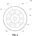
- FIG. 1 and FIG. 2 illustrate an exemplary abrasive article designated 100.
- FIG. 1 includes a front plan view of the abrasive article 100.
- FIG. 2 includes a rear plan view of the abrasive article 100.
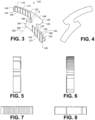
- FIG. 3 through FIG. 8 include various views of a shaped segment that can be installed on the core. Specifically, FIG. 3 includes a front plan view of the segment.
- FIG. 4 includes a rear plan view of the segment.
- FIG. 5 includes a left side plan view.
- FIG. 6 includes a right side plan view.
- FIG. 7 includes a top plan view and
- FIG. 8 includes a bottom plan view of the segment.
- FIG. 8 includes an enlarged bottom plan view of the segment.
- FIG. 1 and 2 illustrates an exemplary abrasive article designated 100.
- the abrasive article 100 can include a generally cup-shaped core 102.
- the core 102 can include a body 104 having a generally disc-shaped central hub 106 formed with a central bore 108 along a center 110 of the core 102.
- the center 110 of the core 102 is also the center 110 of the abrasive article 100.
- a generally frusto-conical sidewall 112 can extend radially outward and axially from the central hub 106 at an angle with respect to the central hub 106.
- the sidewall 112 can include a distal end 114 and a generally ring-shaped segment support flange 116 can extend radially outward from the distal end 114 of the frusto-conical sidewall 112.
- the segment support flange 116 can include a face 118 perpendicular to a direction of rotation of the abrasive article 100 around a central axis passing perpendicularly through the center 110 of the abrasive article 100.
- a plurality of abrasive segments 120 affixed to the face 118 of the segment support flange 116 can extend axially away from the segment support flange 116 in a direction parallel to the central axis.
- the segments 120 can be formed separately from the core 102, as described herein, and affixed to the core via a brazing procedure, a welding procedure, a mechanical coupling, etc.
- each adjacent pair of segments 120 can be separated by a gap 122.
- the segments (120) include a plurality of outer peripheral serrations (172) formed in an outer circumferential wall (162) of the segment.
- FIG. 3 through FIG. 8 illustrate the details of one of the segments 120.
- the segment 120 can include a body 130 that can include a generally curved inner segment portion 132 and a generally curved outer segment portion 134 spaced a radial distance, d, from the inner segment portion 132.
- the body 132 of the segment 130 can also include a central segment portion 136 connected to the inner segment portion 132 and the outer segment portion 134.
- the inner segment portion 132 can include an inner circumferential wall 140 and an outer circumferential wall 142.
- the inner segment portion 132 can also include a leading radial sidewall 144 extending between the inner circumferential wall 140 and the outer circumferential wall 142 and a trailing radial sidewall 146 extending between the inner circumferential wall 140 and the outer circumferential wall 142 opposite the leading radial sidewall 144.
- leading and trailing can be defined based on a direction of rotation of the abrasive article 100, which is counterclockwise in the view illustrated in FIG. 1 .
- the inner segment portion 132 can further include a first grinding face 148 that can extend between the inner and outer circumferential walls 140, 142 and the leading and trailing radial sidewalls 144, 146.
- a first serrated portion 150 can extend at least partially over the first grinding face 148.
- the first grinding face 148 can include an area, A GF1
- the first serrated portion 150 can include an area, A SP1 .
- a SP1 can be ⁇ A GF1 .
- a SP1 can be ⁇ 80% A GF1 , such as ⁇ 75% A GF1 , ⁇ 70% A GF1 , ⁇ 65% A GF1 , or ⁇ 60% A GF1 .
- a SP1 can be ⁇ 30% A GF1 , such as ⁇ 35% A GF1 , ⁇ 40% A GF1 , ⁇ 45% A GF1 , or ⁇ 50% A GF1 .
- a SP1 can be within a range between and including any of the maximum and minimum values of A SP1 described herein.
- a SP1 can be ⁇ 80% A GF1 and ⁇ 30% A GF1 , such as ⁇ 80% A GF1 and ⁇ 35% A GF1 , ⁇ 80% A GF1 and ⁇ 40% A GF1 , ⁇ 80% A GF1 and ⁇ 45% A GF1 , or ⁇ 80% A GF1 and ⁇ 50% A GF1 .
- a SP1 can be ⁇ 75% A GF1 and ⁇ 30% A GF1 , such as ⁇ 75% A GF1 and ⁇ 35% A GF1 , ⁇ 75% A GF1 and ⁇ 40% A GF1 , ⁇ 75% A GF1 and ⁇ 45% A GF1 , or ⁇ 75% A GF1 and ⁇ 50% A GF1 .
- a SP1 can be ⁇ 70% A GF1 and ⁇ 30% A GF1 , such as ⁇ 70% A GF1 and ⁇ 35% A GF1 , ⁇ 70% A GF1 and ⁇ 40% A GF1 , ⁇ 70% A GF1 and ⁇ 45% A GF1 , or ⁇ 70% A GF1 and ⁇ 50% A GF1 .
- a SP1 can be ⁇ 65% A GF1 and ⁇ 30% A GF1 , such as ⁇ 65% A GF1 and ⁇ 35% A GF1 , ⁇ 65% A GF1 and ⁇ 40% A GF1 , ⁇ 65% A GF1 and ⁇ 45% A GF1 , or ⁇ 65% A GF1 and ⁇ 50% A GF1 .
- a SP1 can be ⁇ 60% A GF1 and ⁇ 30% A GF1 , such as ⁇ 60% A GF1 and ⁇ 35% A GF1 , ⁇ 60% A GF1 and ⁇ 40% A GF1 , ⁇ 60% A GF1 and ⁇ 45% A GF1 , or ⁇ 60% A GF1 and ⁇ 50% A GF1 .
- the inner segment portion 132 can have a first radial width, W 1 , measured from the inner circumferential wall 140 to the outer circumferential wall 142.
- W 1 can be ⁇ d, described above.
- W 1 can be ⁇ 105% d, such as ⁇ 110% d, or ⁇ 125% d.
- W 1 can be ⁇ 200% d, such as ⁇ 175% d, or ⁇ 150% d.
- W 1 can also be within a range between and including any of the maximum and minimum values of W 1 described herein.
- W 1 can be ⁇ 105% d and ⁇ 200% d, such as ⁇ 105% d and ⁇ 175% d, or ⁇ 105% d and ⁇ 150% d. Further, W 1 can be ⁇ 110% d and ⁇ 200% d, such as ⁇ 110% d and ⁇ 175% d, or ⁇ 110% d and ⁇ 150% d. Still further, W 1 can be ⁇ 125% d and ⁇ 200% d, such as ⁇ 125% d and ⁇ 175% d, or ⁇ 125% dand ⁇ 150% d.
- the outer segment portion 134 can include an inner circumferential wall 160 and an outer circumferential wall 162.
- the outer segment portion 134 can also include a leading radial sidewall 164 extending between the inner circumferential wall 160 and the outer circumferential wall 162 and a trailing radial sidewall 166 extending between the inner circumferential wall 160 and the outer circumferential wall 162 opposite the leading radial sidewall 164.
- the outer segment portion 134 can further include a second grinding face 168 that can extend between the inner and outer circumferential walls 160, 162 and the leading and trailing radial sidewalls 164, 166.
- a second serrated portion 170 can extend at least partially over the second grinding face 168.
- the second grinding face 168 can include an area, A GF2
- the second serrated portion 170 can include an area, A SP2 .
- a SP2 can be ⁇ A GF2 .
- a SP2 can be ⁇ 80% A GF2 , such as ⁇ 75% A GF2 , ⁇ 70% A GF2 , ⁇ 65% A GF2 , or ⁇ 60% A GF2 .
- a SP2 can be ⁇ 30% A GF2 , such as ⁇ 35% A GF2 , ⁇ 40% A GF2 , ⁇ 45% A GF2 , or ⁇ 50% A GF2 .
- a SP2 can be within a range between and including any of the maximum and minimum values of A SP2 described herein.
- a SP2 can be ⁇ 80% A GF2 and ⁇ 30% A GF2 , such as ⁇ 80% A GF2 and ⁇ 35% A GF2 , ⁇ 80% A GF2 and ⁇ 40% A GF2 , ⁇ 80% A GF2 and ⁇ 45% A GF2 , or ⁇ 80% A GF2 and ⁇ 50% A GF2 .
- a SP2 can be ⁇ 70% A GF2 and ⁇ 30% A GF2 , such as ⁇ 70% A GF2 and ⁇ 35% A GF2 , ⁇ 70% A GF2 and ⁇ 40% A GF2 , ⁇ 70% A GF2 and ⁇ 45% A GF2 , or ⁇ 70% A GF2 and ⁇ 50% A GF2 .
- a SP2 can be ⁇ 65% A GF2 and ⁇ 30% A GF2 , such as ⁇ 65% A GF2 and ⁇ 35% A GF2 , ⁇ 65% A GF2 and ⁇ 40% A GF2 , ⁇ 65% A GF2 and ⁇ 45% A GF2 , or ⁇ 65% A GF2 and ⁇ 50% A GF2 .
- a SP2 can be ⁇ 60% A GF2 and > 30% A GF2 , such as ⁇ 60% A GF2 and ⁇ 35% A GF2 , ⁇ 60% A GF2 and ⁇ 40% A GF2 , ⁇ 60% A GF2 and ⁇ 45% A GF2 , or ⁇ 60% A GF2 and ⁇ 50% A GF2 .
- the outer segment portion 134 can have a second radial width, W 2 , measured from the inner circumferential wall 160 to the outer circumferential wall 162.
- W 2 can be ⁇ d, described above.
- W 2 can be ⁇ 105% d, such as ⁇ 110% d, or ⁇ 125% d.
- W 2 can be ⁇ 200% d, such as ⁇ 175% d, or ⁇ 150% d.
- W 2 can also be within a range between and including any of the maximum and minimum values of W 2 described herein.
- W 2 can be ⁇ 105% d and ⁇ 200% d, such as ⁇ 105% d and ⁇ 175% d, or ⁇ 105% d and ⁇ 150% d.
- W 2 can be ⁇ 110% d and ⁇ 200% d, such as ⁇ 110% d and ⁇ 175% d, or ⁇ 110% d and ⁇ 150% d.
- W 2 can be ⁇ 125% d and ⁇ 200% d, such as ⁇ 125% d and ⁇ 175% d, or ⁇ 125% d and ⁇ 150% d.
- a SP1 can be ⁇ A SP2 .
- a SP1 can be ⁇ 95% A SP2 , such as ⁇ 90% A SP2 , ⁇ 85% A SP2 , or ⁇ 80% A SP2 .
- a SP1 ⁇ 50% A SP2 , such as ⁇ 55% A SP2 , or ⁇ 60% A SP2 .
- a SP1 can be within a range between and including any of the maximum and minimum values of A SP1 described herein.
- a SP1 can be ⁇ 95% A SP2 and ⁇ 50% A SP2 , such as ⁇ 95% A SP2 and ⁇ 55% A SP2 , or ⁇ 95% A SP2 and ⁇ 60% A SP2 .
- a SP1 can be ⁇ 90% A SP2 and ⁇ 50% A SP2 , such as ⁇ 90% A SP2 and ⁇ 55% A SP2 , or ⁇ 90% A SP2 and ⁇ 60% A SP2 .
- a SP1 can be ⁇ 85% A SP2 and ⁇ 50% A SP2 , such as ⁇ 85% A SP2 and ⁇ 55% A SP2 , or ⁇ 85% A SP2 and ⁇ 60% A SP2 .
- a SP1 can be ⁇ 80% A SP2 and ⁇ 50% A SP2 , such as ⁇ 80% A SP2 and ⁇ 55% A SP2 , or ⁇ 80% A SP2 and ⁇ 60% A SP2 .
- the outer segment portion 134 can further include a plurality of outer peripheral serrations 172 formed in the outer circumferential wall 162 of the outer segment portion 134.
- the outer peripheral serrations 172 can extend along the entire outer circumferential wall 162 from the leading radial sidewall 164 to the trailing radial sidewall 166 of the outer segment portion 134.
- the outer peripheral serrations 172 can form a sinusoidal wave structure along the outer circumferential wall 162.
- the outer circumferential wall 162 have a circumferential length, L OCW
- the sinusoidal wave structure can includes a wavelength, WL SWS .
- WL SWS can be ⁇ 0.2 L OCW , such as ⁇ 0.175 L OCW , ⁇ 0.15 L OCW , or ⁇ 0.125 L OCW .
- WL SWS can be ⁇ 0.05 L OCW , such as ⁇ 0.06 L OCW , ⁇ 0.07 L OCW , ⁇ 0.08 L OCW , or ⁇ 0.09 L OCW .
- WL SWS can be within a range between and including any of the maximum and minimum values of WL SWS described herein.
- WL SWS can be ⁇ 0.2 L OCW and ⁇ 0.05 L OCW , such as ⁇ 0.2 L OCW and ⁇ 0.06 L OCW , ⁇ 0.2 L OCW and ⁇ 0.07 L OCW , ⁇ 0.2 L OCW and ⁇ 0.08 L OCW , or ⁇ 0.2 L OCW and ⁇ 0.09 L OCW .
- WL SWS can be ⁇ 0.175 L OCW and ⁇ 0.05 L OCW , such as ⁇ 0.175 L OCW and ⁇ 0.06 L OCW , ⁇ 0.175 L OCW and ⁇ 0.07 L OCW , ⁇ 0.175 L OCW and ⁇ 0.08 L OCW , or ⁇ 0.175 L OCW and ⁇ 0.09 L OCW .
- WL SWS can be ⁇ 0.15 L OCW and ⁇ 0.05 L OCW , such as ⁇ 0.15 L OCW and ⁇ 0.06 L OCW , ⁇ 0.15 L OCW and ⁇ 0.07 L OCW , ⁇ 0.15 L OCW and ⁇ 0.08 L OCW , or ⁇ 0.15 L OCW and ⁇ 0.09 L OCW .
- WL SWS can be ⁇ 0.125 L OCW and ⁇ 0.05 L OCW , such as ⁇ 0.125 L OCW and ⁇ 0.06 L OCW , ⁇ 0.125 L OCW and ⁇ 0.07 L OCW , ⁇ 0.125 L OCW and ⁇ 0.08 L OCW , or ⁇ 0.125 L OCW and ⁇ 0.09 L OCW .
- the central segment portion 136 can include a leading radial sidewall 180 that can extend from the outer circumferential wall 142 of the inner segment portion 132 to the inner circumferential wall 160 of the outer segment portion 134.
- the central segment portion 136 can also include a trailing radial sidewall 182 that can extend from the outer circumferential wall 142 of the inner segment portion 132 to the inner circumferential wall 160 of the outer segment portion 134.
- the leading radial sidewall 180 of the central segment portion 136 can establish an acute angle, ⁇ , with respect to the outer circumferential wall 142 of the inner segment portion 132 and an obtuse angle, ⁇ , with respect the inner circumferential wall 160 of the outer segment portion 136.
- ⁇ can be ⁇ 90°, such as ⁇ 75°, ⁇ 70°, ⁇ 65°, or ⁇ 60°.
- ⁇ can be ⁇ 40°, such as ⁇ 45°, ⁇ 50°, or ⁇ 55°.
- ⁇ can be within a range between and including any of the values of ⁇ described herein.
- ⁇ can be ⁇ 90° and ⁇ 40°, such as ⁇ 90° and ⁇ 45°, ⁇ 90° and ⁇ 50°, or ⁇ 90° and ⁇ 55°.
- ⁇ can be ⁇ 75° and ⁇ 40°, such as ⁇ 75° and ⁇ 45°, ⁇ 75° and ⁇ 50°, or ⁇ 75° and ⁇ 55°.
- ⁇ can be ⁇ 70° and ⁇ 40°, such as ⁇ 70° and ⁇ 45°, ⁇ 70° and ⁇ 50°, or ⁇ 70° and ⁇ 55°.
- ⁇ can be ⁇ 65° and ⁇ 40°, such as ⁇ 65° and ⁇ 45°, ⁇ 65° and ⁇ 50°, or ⁇ 65° and ⁇ 55°.
- ⁇ can be ⁇ 60° and ⁇ 40°, such as ⁇ 60° and ⁇ 45°, ⁇ 60° and ⁇ 50°, or ⁇ 60° and ⁇ 55°.
- ⁇ can be > 90°, such as ⁇ 115°, ⁇ 120°, ⁇ 125°, or ⁇ 130°.
- ⁇ can be ⁇ 150°, such as ⁇ 145°, ⁇ 140°, or ⁇ 135°.
- ⁇ can be within a range between and including any of the maximum and minimum values of ⁇ described herein.
- ⁇ can be > 90° and ⁇ 150°, such as > 90° and ⁇ 145°, > 90° and ⁇ 140°, or > 90° and ⁇ 135°.
- ⁇ can be ⁇ 115° and ⁇ 150°, such as ⁇ 115° and ⁇ 145°, ⁇ 115° and ⁇ 140°, or ⁇ 115° and ⁇ 135°.
- ⁇ can be ⁇ 120° and ⁇ 150°, such as ⁇ 120° and ⁇ 145°, ⁇ 120° and ⁇ 140°, or ⁇ 120° and ⁇ 135°.
- ⁇ can be ⁇ 125° and ⁇ 150°, such as ⁇ 125° and ⁇ 145°, ⁇ 125° and ⁇ 140°, or ⁇ 125° and ⁇ 135°.
- ⁇ can be ⁇ 130° and ⁇ 150°, such as ⁇ 130° and ⁇ 145°, ⁇ 130° and ⁇ 140°, or ⁇ 130° and ⁇ 135°.
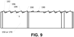
- each serrated portion 150, 170 can include a plurality of serrations 190.
- Each serration includes a leading edge 192, a trailing edge 194, and a ramped surface 196 extending there between.
- each ramped surface 196 can extend at an angle, ⁇ , into the first grinding face 148 or the second grinding face 168 from the trailing edge 194 to the leading edge 192.
- ⁇ can be ⁇ 10°, such as ⁇ 12.5°, or ⁇ 15°.
- ⁇ can be ⁇ 30°, such as ⁇ 25°, or ⁇ 20°.
- ⁇ can be within a range between and including any of the maximum and minimum values described herein.
- ⁇ can be ⁇ 10° and ⁇ 30°, such as ⁇ 10° and ⁇ 25°, or ⁇ 10° and ⁇ 20°.
- ⁇ can be ⁇ 12.5° and ⁇ 30°, such as ⁇ 12.5° and ⁇ 25°, or ⁇ 12.5° and ⁇ 20°.
- ⁇ can be ⁇ 15° and ⁇ 30°, such as ⁇ 15° and ⁇ 25°, or ⁇ 15° and ⁇ 20°.
- the abrasive segment 120 can include a thickness, T AS , measured from a rear face to a front face, e.g., the first grinding face 148 or the second grinding face 168.
- the trailing edge 194 of each serration 190 can extend a distance, D TES , out from the first grinding face 148 or the second grinding face 168 and measured perpendicular to the first grinding face 148 or the second grinding face 168 and D TES can be ⁇ 0.125 T AS , such as ⁇ 0.1 T AS , ⁇ 0.075 T AS , or ⁇ 0.05 T AS .
- D TES can be ⁇ 0.0075 T AS , such as ⁇ 0.01 T AS , ⁇ 0.0125 T AS , or ⁇ 0.015 T AS .
- D TES can be within a range between and including any of the maximum or minimum values of D TES described herein.
- D TES can be ⁇ 0.125 T AS and ⁇ 0.0075 T AS , such as ⁇ 0.125 T AS and ⁇ 0.01 T AS , ⁇ 0.125 T AS and ⁇ 0.0125 T AS , or ⁇ 0.125 T AS and ⁇ 0.015 T AS .
- D TES can be ⁇ 0.1 T AS and ⁇ 0.0075 T AS , such as ⁇ 0.1 T AS and ⁇ 0.01 T AS , ⁇ 0.1 T AS and ⁇ 0.0125 T AS , or ⁇ 0.1 T AS and ⁇ 0.015 T AS .
- D TES can be ⁇ 0.075 T AS and ⁇ 0.0075 T AS , such as ⁇ 0.075 T AS and ⁇ 0.01 T AS , ⁇ 0.075 T AS and ⁇ 0.0125 T AS , or ⁇ 0.075 T AS and ⁇ 0.015 T AS .
- D TES can be ⁇ 0.05 T AS and ⁇ 0.0075 T AS , such as ⁇ 0.05 T AS and ⁇ 0.01 T AS , ⁇ 0.05 T AS and ⁇ 0.0125 T AS , or ⁇ 0.05 T AS and ⁇ 0.015 T AS .
- each serration 190 can extend a distance, D LES , into the first grinding face 148 or the second grinding face 168 and measured perpendicular to the first grinding face 148 or the second grinding face 168, and D LES can be ⁇ 0.125 T AS , such as ⁇ 0.1 T AS , ⁇ 0.075 T AS , or ⁇ 0.05 T AS . Moreover, D LES can be ⁇ 0.0075 T AS , such as ⁇ 0.01 T AS , ⁇ 0.0125 T AS , or > 0.015 T AS . In another aspect, D LES can be within a range between and including any of the maximum or minimum values of D LES described herein.
- D LES can be ⁇ 0.125 T AS and ⁇ 0.0075 T AS , such as ⁇ 0.125 T AS and ⁇ 0.01 T AS , ⁇ 0.125 T AS and ⁇ 0.0125 T AS , or ⁇ 0.125 T AS and ⁇ 0.015 T AS .
- D LES can be ⁇ 0.1 T AS and ⁇ 0.0075 T AS , such as ⁇ 0.1 T AS and ⁇ 0.01 T AS , ⁇ 0.1 T AS and ⁇ 0.0125 T AS , or ⁇ 0.1 T AS and ⁇ 0.015 T AS .
- D LES can be ⁇ 0.075 T AS and ⁇ 0.0075 T AS , such as ⁇ 0.075 T AS and ⁇ 0.01 T AS , ⁇ 0.075 T AS and ⁇ 0.0125 T AS , or ⁇ 0.075 T AS and ⁇ 0.015 T AS .
- D LES can be ⁇ 0.05 T AS and ⁇ 0.0075 T AS , such as ⁇ 0.05 T AS and ⁇ 0.01 T AS , ⁇ 0.05 T AS and ⁇ 0.0125 T AS , or ⁇ 0.05 T AS and ⁇ 0.015 T AS .
- the abrasive segment 120 can include a central axis 200 that can extend through a center 202 of curvature of the abrasive segment and bisect the leading radial sidewall 180 of the central segment portion 136 of the abrasive segment 120.
- the first serrated portion 150 on the first segment portion 132 can lie entirely behind the central axis 200 with respect to a direction of rotation of the abrasive segment 120.
- the second serrated portion 170 on the second segment portion 134 can lie entirely ahead of the central axis 200 with respect to a direction of rotation of the abrasive segment 120.
- a portion of the inner segment portion 132 can extend ahead of the leading radial sidewall 180 of the central segment portion 136 with respect to the direction of rotation.
- a portion of the outer segment portion 134 can extend behind the trailing radial sidewall 182 of the central segment portion 136 with respect to the direction of rotation.
- the core 102 of the abrasive article 100 described herein can be in the form of a cup, a ring, a ring section, a plate, or a disc depending upon the intended application of the abrasive article.
- the core 102 can be made of a metal or metal alloy.
- the core 102 can be made of steel, and particularly, a heat treatable steel alloys, such as 25CrMo4, 75Cr1, C60, or similar steel alloys for a core having a thin cross section or simple construction steel like St 60 or similar for a thick core.
- the core 102 can have a tensile strength of at least about 600 N/mm 2 .
- the core 102 can be formed by a variety of metallurgical techniques known in the art.
- the abrasive segments 104 can include abrasive particles embedded in a bond matrix.
- the bond matrix can include a metal matrix having a network of interconnected pores.
- the abrasive particles can include an abrasive material having a Mohs hardness of at least about 7.
- the abrasive particles can include a superabrasive material, such as diamond or cubic boron nitride.
- the abrasive particles can have a particle size of not less than about 400 US mesh, such as not less than about 100 US mesh, such as between about 25 and 80 US mesh. Depending on the application, the size can be between about 30 and 60 US mesh.
- the abrasive particles can be present in an amount between about 2 vol% to about 50 vol%. Additionally, the amount of abrasive particles may depend on the application. For example, an abrasive segment for a grinding or polishing tool can include between about 3.75 and about 50 vol% abrasive particles of the total volume of the abrasive segment. Alternatively, an abrasive segment for a cutting-off tool can include between about 2 vol% and about 6.25 vol% abrasive particles of the total volume of the abrasive segment. Further, an abrasive segment for core drilling can include between about 6.25 vol% and about 20 vol% abrasive particles of the total volume of the abrasive segment.
- the metal matrix can include a metal element or metal alloy including a plurality of metal elements.
- the metal matrix can include metal elements such as iron, tungsten, cobalt, nickel, chromium, titanium, silver, and a combination thereof.
- the metal matrix can include a rare earth element such as cerium, lanthanum, neodymium, and a combination thereof.
- the metal matrix can include a wear resistant component.
- the metal matrix can include tungsten carbide, and more particularly, may consist essentially of tungsten carbide.
- the metal matrix can include particles of individual components or pre-alloyed particles.
- the particles can be between about 1.0 microns and about 250 microns.
- the abrasive segments 104 can be formed such that an infiltrant is present within the interconnected network of pores within the body of the abrasive segment 104.
- the infiltrant can partially fill, substantially fill, or even completely fill the volume of the pores extending through the volume of the abrasive segment 104.
- the infiltrant can be a metal or metal alloy material.
- some suitable metal elements can include copper, tin, zinc, and a combination thereof.
- the infiltrant can be a bronzing material made of a metal alloy, and particular a copper-tin metal alloy, such that it is particularly suited for welding according to embodiments herein.
- the bronzing material can consist essentially of copper and tin.
- Certain bronzing materials can incorporate particular contents of tin greater than about 5% by weight, such as greater than about 6% by weight, greater than about 7% by weight, or even greater than about 8% by weight. Further, certain bronzing materials can incorporate particular contents of tin less than about 20% by weight, such as less than about 15% by weight, less than about 12% by weight, or even less than about 10% by weight of the total amount of materials within the composition.
- the bronzing material can include an amount of tin within a range between and including about 5% by weight and about 20% by weight, such as between and including about 5% by weight and about 15% by weight, between and including about 5% by weight and about 12% by weight, or between and including about 5% by weight and about 10% by weight.
- the bronzing material can include an amount of tin within a range between and including about 6% by weight and about 20% by weight, such as between and including about 6% by weight and about 15% by weight, between and including about 6% by weight and about 12% by weight, or between and including about 6% by weight and about 10% by weight.
- the bronzing material can include an amount of tin within a range between and including about 7% by weight and about 20% by weight, such as between and including about 7% by weight and about 15% by weight, between and including about 7% by weight and about 12% by weight, or between and including about 7% by weight and about 10% by weight.
- the bronzing material can include an amount of tin within a range between and including about 8% by weight and about 20% by weight, such as between and including about 8% by weight and about 15% by weight, between and including about 8% by weight and about 12% by weight, or between and including about 8% by weight and about 10% by weight.
- certain bronzing materials can be used as infiltrant material, and can have an amount of copper of at least about 80%, at least about 85%, or even at least about 88% by weight of the total amount of materials within the composition.
- Some bronzing materials can utilize an amount of copper within a range between about 80% and about 95%, such as between about 85% and about 95%, or even between about 88% and about 93% by weight of the total amount of materials within the composition.
- the bronzing material may contain a particularly low content of other elements, such as zinc to facilitate proper formation of the abrasive article according to the forming methods of the embodiments herein.
- the bronzing material may utilize not greater than about 10%, such as not greater than about 5%, or even not greater than about 2% zinc. In fact, certain bronzing materials can be essentially free of zinc.
- the abrasive segment 104 may be manufactured, such that abrasive particles can be combined with a metal matrix to form a mixture.
- the metal matrix can include a blend of particles of the components of the metal matrix or can be pre-alloyed particles of the metal matrix.
- the metal matrix can conform to the formula (WC) w W x Fe y Cr z X (1-w-x-y-z) , wherein 0 ⁇ w ⁇ 0.8, 0 ⁇ x ⁇ 0.7, 0 ⁇ y ⁇ 0.8, 0 ⁇ z ⁇ 0.05, w+x+y+z ⁇ 1, and X can include other metals such as cobalt and nickel.
- the metal matrix can conform to the formula (WC) w W x Fe y Cr z Ag v X (1-v-w-x-y-z) , wherein 0 ⁇ w ⁇ 0.5, 0 ⁇ x ⁇ 0.4, 0 ⁇ y ⁇ 1.0, 0 ⁇ z ⁇ 0.05, 0 ⁇ v ⁇ 0.1, v+w+x+y+z ⁇ 1, and X can include other metals such as cobalt and nickel.
- the mixture of metal matrix and abrasive particles can be formed into an abrasive preform by a pressing operation, particularly a cold pressing operation, to form a porous abrasive segment.
- the cold pressing can be carried out at a pressure within a range between and including about 50 kN/cm 2 (500 MPa) to about 250 kN/cm 2 (2500 MPa).
- the resulting porous abrasive segment can have a network of interconnected pores.
- the porous abrasive segment can have a porosity between about 25 and 50 vol%.
- the resulting porous abrasive segment 104 can then be subject to an infiltration process, wherein the infiltrant material is disposed within the body of the abrasive segment, and particularly, disposed within the interconnected network of pores within the body of the abrasive segment.
- the infiltrant may be drawn into the pores of the cold pressed abrasive segment via capillary action.
- the resulting densified abrasive segment can be not less than about 96% dense.
- the amount of infiltrant that infiltrates the abrasive segment can be between about 20 wt% and 45 wt% of the densified abrasive segment.
- the abrasive segment 104 can include a backing region, disposed between the abrasive segment and the base, i.e., the core 102, which facilitates the joining of the abrasive segment and the core 102.
- the backing region can be a distinct region from the abrasive segment 104 and the core 102.
- the backing region can be initially formed as part of the abrasive segment 104, and particularly may be a distinct region of the abrasive segment 104 along a bottom surface of the abrasive segment 104 that has particular characteristics facilitating the joining of the abrasive segment 104 and the core 102.
- the backing region can have a lesser percentage (vol%) of abrasive particles as compared to the amount of abrasive particles within the abrasive segment 104.
- the backing region can be essentially free of abrasive particles. This may be particularly suitable for forming methods utilizing a beam of energy (e.g., a laser) used to weld the abrasive segment 104 to the core 102.
- a beam of energy e.g., a laser
- the bonding composition can include a metal or metal alloy.
- suitable metal materials can include transition metal elements, including for example, titanium, silver, manganese, phosphorus, aluminum, magnesium, chromium, iron, lead, copper, tin, and a combination thereof.
- the bonding composition can be similar to the infiltrant, such that the bonding composition and the infiltrant are different from each other by not greater than a single elemental species.
- the bonding composition can be the same as the infiltrant.
- the bonding composition can be related to the infiltrant composition in having a certain degree of commonality of elemental species. Quantitatively, an elemental weight percent difference between the bonding composition and the infiltrant composition does not exceed 20 weight percent. Elemental weight percent difference is defined as the absolute value of the difference in weight content of each element contained in the bonding composition relative to the infiltrant composition. Other embodiments have closer compositional relationships between the bonding composition and the composition of the infiltrant.
- the elemental weight percent difference between the bonding composition and the infiltrant composition may, for example, not exceed 15 weight percent, 10 weight percent, 5 weight percent, or may not exceed 2 weight percent.
- An elemental weight percent difference of about zero represents the same composition making up the backing region and the infiltrant.
- the foregoing elemental values may be measured by any suitable analytical means, including microprobe elemental analysis, and ignores alloying that might take place along areas in which the infiltrant contacts the metal matrix.
- the backing region can include at least about 90 wt% infiltrant, such as at least about 95 wt% infiltrant, such as at least about 98 wt% infiltrant.
- the infiltrant can be continuous throughout the backing region and the densified abrasive segment.
- the backing region can be formed primarily of the infiltrant material, and in more particular instances, can consist essentially of the infiltrant material.
- the backing region can be an infiltrated region, like the abrasive segment. Accordingly, the backing region can include a network of interconnected pores formed between a matrix metal, and wherein the infiltrant material substantially fills the interconnected pores.
- the backing region can contain similar amounts of matrix metal and infiltrant.
- the backing region may be essentially free of abrasive particles.
- the infiltrant material can act as a bronzing material in forming a joint (e.g., a welded joint) between the base and the abrasive segment.
- the backing region can be formed of the bronzing material described herein.
- certain backing regions can consist essentially of a copper-tin bronzing material having about 88% copper and 12% tin or 90% copper and 10% tin.
- a method of making the abrasive article 100 can include stamping, cutting, drilling, or otherwise forming a core 102 having vibration reducing gullets 140 and segment support structures 130.
- the method can include affixing the segments 104 to the core 102 such that each segment 104 is affixed to a segment support structure 130.
- Affixing the segments 104 to the core 102 can include welding the abrasive segments 104 to the core 102.
- the welding process can include impinging a beam of energy at the base of each segment 104. More particularly, in the instance of a segment 104 having a backing region, welding can include impinging a beam of energy at the backing region between the abrasive segment 104 and the core 102.
- the beam of energy can be a laser, such that each abrasive segment 104 is attached to the core 102 via a laser welded bond joint.
- the laser may be a Roffin laser source commonly available from Dr. Fritsch, GmbH.
- each segment 104 can be formed by pressing a green segment in a mold and curing the green segment.
- the pressing can include hot pressing or cold pressing.
- forming each segment 104 can include sintering a green segment, e.g., using an electro-discharge sintering process.
- forming each segment 104 can include the infiltration method described herein.
- each segment 104 can be include a single layer metal bond (“SLMB") segment having a core and a single layer of abrasive electro-plated, or otherwise deposited, on a cutting, or grinding surface of the core.
- SLMB single layer metal bond
- each abrasive article 100 can include a carrier element, e.g., a core 102, and an abrasive component, e.g., a segment 104.
- the abrasive article 100 can be a cutting tool for cutting construction materials, such as a saw for cutting concrete.
- the abrasive article 100 can be a grinding tool such as for grinding concrete or fired clay or removing asphalt.
Landscapes
- Engineering & Computer Science (AREA)
- Mechanical Engineering (AREA)
- Chemical & Material Sciences (AREA)
- Mining & Mineral Resources (AREA)
- Ceramic Engineering (AREA)
- Inorganic Chemistry (AREA)
- Manufacturing & Machinery (AREA)
- Polishing Bodies And Polishing Tools (AREA)
Claims (15)
- Abrasiver Artikel (100), umfassend:einen Körper; undeine Vielzahl von Z-förmigen abrasiven Segmenten, die sich von einer Fläche des Körpers aus erstrecken, dadurch gekennzeichnet, dass die Z-förmigen abrasiven Segmente ein Segment (120) umfassen,einschließlich einer Vielzahl von äußeren peripheren Zacken (172), die in einer äußeren Umfangswand (162) des Segments ausgebildet sind.
- Abrasiver Artikel (100) nach Anspruch 1, wobei sich die Vielzahl von äußeren Umfangszacken (172) entlang der gesamten äußeren Umfangswand (162) erstreckt.
- Abrasiver Artikel (100) nach Anspruch 1 oder 2, wobei das Segment (120) einen inneren Segmentabschnitt (132) und einen äußeren Segmentabschnitt (134), einschließlich der äußeren Umfangswand (162) und um einen radialen Abstand d von dem inneren Segmentabschnitt (132) beabstandet, umfasst.
- Abrasiver Artikel (100) nach Anspruch 3, wobei der innere Segmentabschnitt (132) eine äußere Umfangswand (142) und eine innere Umfangswand (140) gegenüber der äußeren Umfangswand (142) umfasst, wobei die äußere Umfangswand (142) keine Umfangszacken aufweist und wobei die innere Umfangswand (140) des inneren Segmentabschnitts (132) keine Umfangszacken aufweist.
- Abrasiver Artikel (100) nach einem der Ansprüche 1 bis 4, wobei das Segment (120) eine innere Umfangswand (160) und eine Schleiffläche (168) umfasst, die sich zwischen der inneren Umfangswand (160) und der äußeren Umfangswand (162) erstreckt.
- Abrasiver Artikel nach einem der Ansprüche 1 bis 5, wobei das Segment (120) einen gezackten Abschnitt (170) aufweist, der von den äußeren peripheren Zacken (172) getrennt ist.
- Abrasiver Artikel (100) nach Anspruch 6, wobei sich der gezackte Abschnitt (170) mindestens teilweise über die Schleiffläche (168) erstreckt.
- Abrasiver Artikel (100) nach einem der Ansprüche 2 bis 6, wobei die Vielzahl von äußeren Umfangszacken (172) entlang der äußeren Umfangswand (162) eine sinusförmige Wellenstruktur ausbildet.
- Abrasiver Artikel (100) nach Anspruch 8, wobei die äußere Umfangswand (162) eine Länge LOCW aufweist und die sinusförmige Wellenstruktur eine Wellenlänge WLSWS einschließt, wobei WLSWS ≦ 0,2 LOCW.
- Abrasiver Artikel (100) nach Anspruch 9, wobei WLSWS ≧ 0,05 LOCW.
- Abrasiver Artikel (100) nach einem der Ansprüche 1 bis 10, wobei jedes der Vielzahl von Z-förmigen abrasiven Segmenten eine äußere Umfangswand (162) und eine Vielzahl von äußeren Umfangszacken (172) umfasst, die in der äußeren Umfangswand (162) ausgebildet sind, wobei die äußeren Umfangswände (162) der Vielzahl von Z-förmigen abrasiven Segmenten voneinander beabstandet sind.
- Abrasiver Artikel (100) nach einem der Ansprüche 1 bis 10, wobei die Vielzahl von Z-förmigen abrasiven Segmente voneinander beabstandet sind.
- Abrasiver Artikel (100) nach einem der Ansprüche 1 bis 11, wobei jedes der Z-förmigen abrasiven Segmente umfasst:einen inneren Segmentabschnitt (132);einen äußeren Segmentabschnitt (134), der in einem radialen Abstand d von dem inneren Segmentabschnitt (132) beabstandet ist, der äußere Segmentabschnitt (134) umfassend eine äußere Umfangswand (162) und eine Vielzahl von äußeren Umfangszacken (172), die in der äußeren Umfangswand (162) ausgebildet sind; undeinen zentralen Segmentabschnitt (136), der mit dem inneren Segmentabschnitt (132) und dem äußeren Segmentabschnitt (134) verbunden ist.
- Abrasiver Artikel (100) nach Anspruch 13, wobei der innere Segmentabschnitt (132) eine äußere Umfangswand (142), eine innere Umfangswand (140) und eine Schleiffläche (148) umfasst, die sich zwischen der äußeren Umfangswand (142) und der inneren Umfangswand (140) erstreckt.
- Abrasiver Artikel (100) nach Anspruch 13 oder 14, wobei der äußere Segmentabschnitt (134) ferner eine innere Umfangswand (160) und eine Schleiffläche (168) umfasst, die sich zwischen der inneren Umfangswand (160) und der äußeren Umfangswand (162) erstreckt.
Applications Claiming Priority (3)
| Application Number | Priority Date | Filing Date | Title |
|---|---|---|---|
| US201261747965P | 2012-12-31 | 2012-12-31 | |
| PCT/US2013/076569 WO2014105638A1 (en) | 2012-12-31 | 2013-12-19 | Abrasive article having shaped segments |
| EP13868740.5A EP2938463B1 (de) | 2012-12-31 | 2013-12-19 | Schleifartikel mit geformten segmenten |
Related Parent Applications (1)
| Application Number | Title | Priority Date | Filing Date |
|---|---|---|---|
| EP13868740.5A Division EP2938463B1 (de) | 2012-12-31 | 2013-12-19 | Schleifartikel mit geformten segmenten |
Publications (2)
| Publication Number | Publication Date |
|---|---|
| EP3666463A1 EP3666463A1 (de) | 2020-06-17 |
| EP3666463B1 true EP3666463B1 (de) | 2024-09-18 |
Family
ID=51017691
Family Applications (2)
| Application Number | Title | Priority Date | Filing Date |
|---|---|---|---|
| EP20150800.9A Active EP3666463B1 (de) | 2012-12-31 | 2013-12-19 | Schleifartikel mit geformten segmenten |
| EP13868740.5A Active EP2938463B1 (de) | 2012-12-31 | 2013-12-19 | Schleifartikel mit geformten segmenten |
Family Applications After (1)
| Application Number | Title | Priority Date | Filing Date |
|---|---|---|---|
| EP13868740.5A Active EP2938463B1 (de) | 2012-12-31 | 2013-12-19 | Schleifartikel mit geformten segmenten |
Country Status (6)
| Country | Link |
|---|---|
| US (3) | US9149913B2 (de) |
| EP (2) | EP3666463B1 (de) |
| KR (1) | KR101803704B1 (de) |
| AU (1) | AU2013371043B2 (de) |
| PL (1) | PL2938463T3 (de) |
| WO (1) | WO2014105638A1 (de) |
Families Citing this family (15)
| Publication number | Priority date | Publication date | Assignee | Title |
|---|---|---|---|---|
| US9149913B2 (en) | 2012-12-31 | 2015-10-06 | Saint-Gobain Abrasives, Inc. | Abrasive article having shaped segments |
| WO2016019306A2 (en) * | 2014-08-01 | 2016-02-04 | Saint-Gobain Abrasives, Inc. | Abrasive article including z-shaped abrasive segments |
| TWI599454B (zh) * | 2015-03-04 | 2017-09-21 | 聖高拜磨料有限公司 | 磨料製品及使用方法 |
| US10932402B2 (en) * | 2016-10-11 | 2021-03-02 | Deere & Company | Wear resistant disk blade and agricultural machine with wear resistant disk blade |
| CN108015906A (zh) * | 2016-10-28 | 2018-05-11 | 圣戈班磨料磨具有限公司 | 空芯钻头及其制造方法 |
| CN108237484A (zh) * | 2016-12-26 | 2018-07-03 | 圣戈班磨料磨具有限公司 | 形成研磨制品的方法 |
| JP6844430B2 (ja) * | 2017-06-09 | 2021-03-17 | 信越化学工業株式会社 | 外周切断刃及びその製造方法 |
| WO2021217044A1 (en) | 2020-04-23 | 2021-10-28 | Saint-Gobain Abrasives, Inc. | System and method for conducting an abrasive operation |
| CN112706084B (zh) * | 2020-12-28 | 2021-12-10 | 湖南理工学院 | 一种自适应供给瞬时冷却分块式结构化金刚石砂轮 |
| JP2024509813A (ja) | 2021-03-05 | 2024-03-05 | サンーゴバン アブレイシブズ,インコーポレイティド | 研磨物品及びそれを形成するための方法 |
| WO2022187720A1 (en) | 2021-03-05 | 2022-09-09 | Saint-Gobain Abrasives, Inc. | Abrasive articles and methods for forming same |
| WO2023130015A1 (en) | 2021-12-29 | 2023-07-06 | Saint-Gobain Abrasives, Inc. | Abrasive articles and methods for forming same |
| CN118541240B (zh) | 2021-12-30 | 2025-11-07 | 圣戈班磨料磨具有限公司 | 磨料制品及其形成方法 |
| US12064850B2 (en) | 2021-12-30 | 2024-08-20 | Saint-Gobain Abrasives, Inc. | Abrasive articles and methods for forming same |
| WO2023225356A1 (en) | 2022-05-20 | 2023-11-23 | 3M Innovative Properties Company | Abrasive assembly with abrasive segments |
Family Cites Families (65)
| Publication number | Priority date | Publication date | Assignee | Title |
|---|---|---|---|---|
| US487198A (en) * | 1892-11-29 | Apparatus for cleanxng shipsj bottoms | ||
| US232682A (en) * | 1880-09-28 | chase | ||
| USRE23717E (en) * | 1953-09-29 | Abrasive block or segment | ||
| USRE15245E (en) * | 1921-12-06 | Daniel frederick mcgovern | ||
| US970618A (en) * | 1908-01-31 | 1910-09-20 | Roland Gardner | Abrading-wheel. |
| US931483A (en) * | 1908-03-16 | 1909-08-17 | Puffer Mfg Company | Grinder-head. |
| US1027536A (en) * | 1911-08-05 | 1912-05-28 | Roland Gardner | Abrading-wheel. |
| US1074347A (en) * | 1912-12-02 | 1913-09-30 | Alonzo K Collins | Calculating-register. |
| US1470957A (en) | 1920-04-12 | 1923-10-16 | Cavicchi Ercole | Rotary grinding or polishing tool |
| US1868492A (en) * | 1929-03-28 | 1932-07-26 | Sterling Grinding Wheel Compan | Grinding wheel |
| US2307312A (en) | 1941-09-04 | 1943-01-05 | Draper Corp | Abrading wheel |
| US2307632A (en) | 1942-02-27 | 1943-01-05 | Cortland Grinding Wheels Corp | Segmental grinding wheel |
| US2408148A (en) * | 1944-03-04 | 1946-09-24 | Longbotham Thomas | Diamond charged saw blade and method of making same |
| US2883807A (en) * | 1956-09-18 | 1959-04-28 | Titcomb Albert Shepard | Segmental bonded abrasive bodies |
| US3298806A (en) * | 1961-12-27 | 1967-01-17 | Felker Mfg Company | Method for making abrasive segments for saws |
| US3863401A (en) | 1971-06-16 | 1975-02-04 | Ferro Corp | Diamond abrasive cut-off wheel |
| US3754355A (en) | 1971-06-23 | 1973-08-28 | Mwa Co | Segmental grinding wheel |
| US3745719A (en) * | 1971-12-13 | 1973-07-17 | F Oswald | Grinding wheel for floor grinding machine |
| US4212137A (en) | 1978-07-20 | 1980-07-15 | Norton Company | Segmental grinding wheel and composite abrading segments therefor |
| US4624237A (en) * | 1984-06-08 | 1986-11-25 | Jiro Inoue | Diamond saw |
| JPS6190876A (ja) * | 1984-10-08 | 1986-05-09 | Hiroshi Ishizuka | 超砥粒電着丸鋸 |
| US5654246A (en) * | 1985-02-04 | 1997-08-05 | Lanxide Technology Company, Lp | Methods of making composite ceramic articles having embedded filler |
| KR910018147A (ko) * | 1989-04-17 | 1991-11-30 | 히로아끼 오끼나가 | 회전 커터 블레이드 |
| US5177908A (en) * | 1990-01-22 | 1993-01-12 | Micron Technology, Inc. | Polishing pad |
| US5791330A (en) * | 1991-06-10 | 1998-08-11 | Ultimate Abrasive Systems, L.L.C. | Abrasive cutting tool |
| GB9223826D0 (en) | 1992-11-13 | 1993-01-06 | De Beers Ind Diamond | Abrasive device |
| US5560348A (en) * | 1994-06-02 | 1996-10-01 | Diamant Boart, Inc. | Cutting blade with an impact load prevention layer |
| DE19707445A1 (de) * | 1997-02-25 | 1998-08-27 | Hilti Ag | Topfförmige Schleifscheibe |
| EP0989924B1 (de) * | 1998-04-21 | 2002-12-18 | Tyrolit Schleifmittelwerke Swarovski KG | Schleifscheibe |
| USD437540S1 (en) | 1999-04-11 | 2001-02-13 | Sankyo Diamond Industrial Co., Ltd. | Diamond wheel |
| KR100314287B1 (ko) | 1999-07-29 | 2001-11-23 | 김세광 | 연마 휠 |
| USD442196S1 (en) | 2000-02-03 | 2001-05-15 | Sandvik Aktiebolag | Cutting insert for chip forming machining |
| JP2001280441A (ja) | 2000-03-29 | 2001-10-10 | Toyota Autom Loom Works Ltd | 動力伝達機構 |
| AU145177S (en) | 2000-05-12 | 2001-09-11 | Veisto Rakenne Rautio O Y | Cutter bit |
| USD463965S1 (en) | 2001-02-15 | 2002-10-08 | Ehwa Diamond Ind. Co., Ltd. | Grinding wheel |
| KR100433194B1 (ko) | 2001-02-19 | 2004-05-28 | 이화다이아몬드공업 주식회사 | 편마모방지용 세그먼트를 갖는 연마휠 |
| US20020178890A1 (en) * | 2001-04-19 | 2002-12-05 | Yukio Okuda | Cutting tool |
| JP2003117833A (ja) * | 2001-10-15 | 2003-04-23 | Shin Etsu Chem Co Ltd | 研磨加工板 |
| BE1014434A3 (fr) | 2001-10-19 | 2003-10-07 | Carbodiam | Methode de conception et de fabrication d'outil de coupe destine a l'enlevement de revetements sur substrats mineraux. |
| USD474954S1 (en) | 2001-11-16 | 2003-05-27 | Ehwa Diamond Industrial Co., Ltd. | Grinding cup |
| DE10161931A1 (de) * | 2001-12-17 | 2003-06-18 | Hilti Ag | Schleifscheibe mit Schleifsegmenten |
| USD510586S1 (en) | 2002-10-03 | 2005-10-11 | Sollami Jimmie L | Drill bit blade |
| USD481045S1 (en) | 2002-11-05 | 2003-10-21 | Ehwa Diamond Industrial Co., Ltd. | Tip for core drill |
| US6949012B2 (en) * | 2002-12-10 | 2005-09-27 | Intel Corporation | Polishing pad conditioning method and apparatus |
| USD502712S1 (en) | 2003-10-28 | 2005-03-08 | Iggesund Tools Ab | Debarking tool |
| US7066795B2 (en) * | 2004-10-12 | 2006-06-27 | Applied Materials, Inc. | Polishing pad conditioner with shaped abrasive patterns and channels |
| USD537854S1 (en) | 2004-12-29 | 2007-03-06 | Manchester Tool Company | Cutting insert |
| ITMO20050005U1 (it) * | 2005-03-23 | 2006-09-21 | Giovanni Ficai | Mola da taglio perfezionata |
| DE102005054578A1 (de) * | 2005-11-16 | 2007-05-24 | Robert Bosch Gmbh | Trennscheibe |
| USD548758S1 (en) | 2006-09-13 | 2007-08-14 | Rin-Soon Park | Abrasive segment |
| USD595750S1 (en) | 2006-12-15 | 2009-07-07 | Sandvik Intellectual Property Ab | Cutting insert element |
| USD566141S1 (en) | 2007-02-23 | 2008-04-08 | Rin-Soon Park | Abrasive agent |
| USD607025S1 (en) | 2007-12-04 | 2009-12-29 | Seco Tools Ab | Cutting insert for chip removal |
| USD582446S1 (en) | 2008-02-01 | 2008-12-09 | Rin Soon Park | Abrasive segment |
| CN102076462B (zh) * | 2008-07-02 | 2013-01-16 | 圣戈班磨料磨具有限公司 | 用于电子工业中的磨料切片工具 |
| US8261632B2 (en) * | 2008-07-09 | 2012-09-11 | Baker Hughes Incorporated | Methods of forming earth-boring drill bits |
| MX2011001443A (es) * | 2008-08-08 | 2011-04-11 | Saint Gobain Abrasives Inc | Herramientas abrasivas que tienen una fase de metal continua para unir un componente abrasivo a un portador. |
| KR101097173B1 (ko) * | 2009-09-04 | 2011-12-22 | 신한다이아몬드공업 주식회사 | 절삭/연마 공구 및 그 제조방법 |
| MY163817A (en) * | 2009-12-11 | 2017-10-31 | Saint Gobain Abrasives Inc | Abrasive article for use with a grinding wheel |
| KR100987579B1 (ko) * | 2009-12-14 | 2010-10-12 | (주)성심 | 연마용 툴의 탈부착이 용이한 연마 휠 어셈블리 |
| MX343779B (es) * | 2009-12-31 | 2016-11-23 | Saint Gobain Abrasives Inc | Artículo abrasivo que incorpora un segmento abrasivo infiltrado. |
| USD624569S1 (en) | 2010-04-14 | 2010-09-28 | Mora Of Sweden Ab | Bore crown for ice drill |
| EP2760637A4 (de) * | 2011-09-29 | 2015-10-21 | Saint Gobain Abrasives Inc | Durch uniaxiales heisspressen geformte gebundene schleifmittel |
| US9149913B2 (en) | 2012-12-31 | 2015-10-06 | Saint-Gobain Abrasives, Inc. | Abrasive article having shaped segments |
| USD698375S1 (en) | 2012-12-31 | 2014-01-28 | Saint-Gobain Abrasives, Inc. | Abrasive article having shaped segments |
-
2013
- 2013-12-18 US US14/132,140 patent/US9149913B2/en active Active
- 2013-12-19 EP EP20150800.9A patent/EP3666463B1/de active Active
- 2013-12-19 WO PCT/US2013/076569 patent/WO2014105638A1/en not_active Ceased
- 2013-12-19 EP EP13868740.5A patent/EP2938463B1/de active Active
- 2013-12-19 AU AU2013371043A patent/AU2013371043B2/en not_active Expired - Fee Related
- 2013-12-19 PL PL13868740T patent/PL2938463T3/pl unknown
- 2013-12-19 KR KR1020157019876A patent/KR101803704B1/ko active Active
-
2015
- 2015-09-02 US US14/843,755 patent/US9700993B2/en active Active
-
2017
- 2017-06-05 US US15/613,868 patent/US10456890B2/en active Active
Also Published As
| Publication number | Publication date |
|---|---|
| AU2013371043B2 (en) | 2016-12-08 |
| US9149913B2 (en) | 2015-10-06 |
| KR20150100834A (ko) | 2015-09-02 |
| US20140187130A1 (en) | 2014-07-03 |
| EP2938463A1 (de) | 2015-11-04 |
| EP2938463B1 (de) | 2020-02-05 |
| US20150375368A1 (en) | 2015-12-31 |
| US20170266782A1 (en) | 2017-09-21 |
| AU2013371043A1 (en) | 2015-07-30 |
| PL2938463T3 (pl) | 2020-07-27 |
| KR101803704B1 (ko) | 2017-12-01 |
| EP3666463A1 (de) | 2020-06-17 |
| EP2938463A4 (de) | 2016-10-19 |
| US10456890B2 (en) | 2019-10-29 |
| US9700993B2 (en) | 2017-07-11 |
| WO2014105638A1 (en) | 2014-07-03 |
Similar Documents
| Publication | Publication Date | Title |
|---|---|---|
| EP2938463B1 (de) | Schleifartikel mit geformten segmenten | |
| EP2938462B1 (de) | Schleifmittel mit schleifsegmenten mit geformten rinnenwänden | |
| EP3578299B1 (de) | Schleifkörper | |
| EP2519381B1 (de) | Schleifartikel mit einem infiltriertem schleifsegment | |
| US20140010998A1 (en) | Abrasive article having reversible interchangeable abrasive segments | |
| AU2017388035A1 (en) | Process of forming an abrasive article | |
| US12559657B2 (en) | Abrasive articles and methods for forming same | |
| WO2016019306A2 (en) | Abrasive article including z-shaped abrasive segments |
Legal Events
| Date | Code | Title | Description |
|---|---|---|---|
| PUAI | Public reference made under article 153(3) epc to a published international application that has entered the european phase |
Free format text: ORIGINAL CODE: 0009012 |
|
| STAA | Information on the status of an ep patent application or granted ep patent |
Free format text: STATUS: THE APPLICATION HAS BEEN PUBLISHED |
|
| AC | Divisional application: reference to earlier application |
Ref document number: 2938463 Country of ref document: EP Kind code of ref document: P |
|
| AK | Designated contracting states |
Kind code of ref document: A1 Designated state(s): AL AT BE BG CH CY CZ DE DK EE ES FI FR GB GR HR HU IE IS IT LI LT LU LV MC MK MT NL NO PL PT RO RS SE SI SK SM TR |
|
| STAA | Information on the status of an ep patent application or granted ep patent |
Free format text: STATUS: REQUEST FOR EXAMINATION WAS MADE |
|
| 17P | Request for examination filed |
Effective date: 20201216 |
|
| RBV | Designated contracting states (corrected) |
Designated state(s): AL AT BE BG CH CY CZ DE DK EE ES FI FR GB GR HR HU IE IS IT LI LT LU LV MC MK MT NL NO PL PT RO RS SE SI SK SM TR |
|
| STAA | Information on the status of an ep patent application or granted ep patent |
Free format text: STATUS: EXAMINATION IS IN PROGRESS |
|
| 17Q | First examination report despatched |
Effective date: 20230721 |
|
| GRAP | Despatch of communication of intention to grant a patent |
Free format text: ORIGINAL CODE: EPIDOSNIGR1 |
|
| STAA | Information on the status of an ep patent application or granted ep patent |
Free format text: STATUS: GRANT OF PATENT IS INTENDED |
|
| INTG | Intention to grant announced |
Effective date: 20240510 |
|
| GRAS | Grant fee paid |
Free format text: ORIGINAL CODE: EPIDOSNIGR3 |
|
| GRAA | (expected) grant |
Free format text: ORIGINAL CODE: 0009210 |
|
| STAA | Information on the status of an ep patent application or granted ep patent |
Free format text: STATUS: THE PATENT HAS BEEN GRANTED |
|
| AC | Divisional application: reference to earlier application |
Ref document number: 2938463 Country of ref document: EP Kind code of ref document: P |
|
| AK | Designated contracting states |
Kind code of ref document: B1 Designated state(s): AL AT BE BG CH CY CZ DE DK EE ES FI FR GB GR HR HU IE IS IT LI LT LU LV MC MK MT NL NO PL PT RO RS SE SI SK SM TR |
|
| REG | Reference to a national code |
Ref country code: GB Ref legal event code: FG4D |
|
| REG | Reference to a national code |
Ref country code: CH Ref legal event code: EP |
|
| REG | Reference to a national code |
Ref country code: DE Ref legal event code: R096 Ref document number: 602013086112 Country of ref document: DE |
|
| REG | Reference to a national code |
Ref country code: IE Ref legal event code: FG4D |
|
| P01 | Opt-out of the competence of the unified patent court (upc) registered |
Free format text: CASE NUMBER: APP_51281/2024 Effective date: 20240911 |
|
| REG | Reference to a national code |
Ref country code: LT Ref legal event code: MG9D |
|
| PG25 | Lapsed in a contracting state [announced via postgrant information from national office to epo] |
Ref country code: NO Free format text: LAPSE BECAUSE OF FAILURE TO SUBMIT A TRANSLATION OF THE DESCRIPTION OR TO PAY THE FEE WITHIN THE PRESCRIBED TIME-LIMIT Effective date: 20241218 |
|
| PG25 | Lapsed in a contracting state [announced via postgrant information from national office to epo] |
Ref country code: GR Free format text: LAPSE BECAUSE OF FAILURE TO SUBMIT A TRANSLATION OF THE DESCRIPTION OR TO PAY THE FEE WITHIN THE PRESCRIBED TIME-LIMIT Effective date: 20241219 Ref country code: FI Free format text: LAPSE BECAUSE OF FAILURE TO SUBMIT A TRANSLATION OF THE DESCRIPTION OR TO PAY THE FEE WITHIN THE PRESCRIBED TIME-LIMIT Effective date: 20240918 |
|
| PG25 | Lapsed in a contracting state [announced via postgrant information from national office to epo] |
Ref country code: BG Free format text: LAPSE BECAUSE OF FAILURE TO SUBMIT A TRANSLATION OF THE DESCRIPTION OR TO PAY THE FEE WITHIN THE PRESCRIBED TIME-LIMIT Effective date: 20240918 |
|
| PG25 | Lapsed in a contracting state [announced via postgrant information from national office to epo] |
Ref country code: LV Free format text: LAPSE BECAUSE OF FAILURE TO SUBMIT A TRANSLATION OF THE DESCRIPTION OR TO PAY THE FEE WITHIN THE PRESCRIBED TIME-LIMIT Effective date: 20240918 |
|
| PG25 | Lapsed in a contracting state [announced via postgrant information from national office to epo] |
Ref country code: HR Free format text: LAPSE BECAUSE OF FAILURE TO SUBMIT A TRANSLATION OF THE DESCRIPTION OR TO PAY THE FEE WITHIN THE PRESCRIBED TIME-LIMIT Effective date: 20240918 |
|
| REG | Reference to a national code |
Ref country code: NL Ref legal event code: MP Effective date: 20240918 |
|
| PG25 | Lapsed in a contracting state [announced via postgrant information from national office to epo] |
Ref country code: RS Free format text: LAPSE BECAUSE OF FAILURE TO SUBMIT A TRANSLATION OF THE DESCRIPTION OR TO PAY THE FEE WITHIN THE PRESCRIBED TIME-LIMIT Effective date: 20241218 |
|
| PG25 | Lapsed in a contracting state [announced via postgrant information from national office to epo] |
Ref country code: RS Free format text: LAPSE BECAUSE OF FAILURE TO SUBMIT A TRANSLATION OF THE DESCRIPTION OR TO PAY THE FEE WITHIN THE PRESCRIBED TIME-LIMIT Effective date: 20241218 Ref country code: NO Free format text: LAPSE BECAUSE OF FAILURE TO SUBMIT A TRANSLATION OF THE DESCRIPTION OR TO PAY THE FEE WITHIN THE PRESCRIBED TIME-LIMIT Effective date: 20241218 Ref country code: LV Free format text: LAPSE BECAUSE OF FAILURE TO SUBMIT A TRANSLATION OF THE DESCRIPTION OR TO PAY THE FEE WITHIN THE PRESCRIBED TIME-LIMIT Effective date: 20240918 Ref country code: HR Free format text: LAPSE BECAUSE OF FAILURE TO SUBMIT A TRANSLATION OF THE DESCRIPTION OR TO PAY THE FEE WITHIN THE PRESCRIBED TIME-LIMIT Effective date: 20240918 Ref country code: GR Free format text: LAPSE BECAUSE OF FAILURE TO SUBMIT A TRANSLATION OF THE DESCRIPTION OR TO PAY THE FEE WITHIN THE PRESCRIBED TIME-LIMIT Effective date: 20241219 Ref country code: FI Free format text: LAPSE BECAUSE OF FAILURE TO SUBMIT A TRANSLATION OF THE DESCRIPTION OR TO PAY THE FEE WITHIN THE PRESCRIBED TIME-LIMIT Effective date: 20240918 Ref country code: BG Free format text: LAPSE BECAUSE OF FAILURE TO SUBMIT A TRANSLATION OF THE DESCRIPTION OR TO PAY THE FEE WITHIN THE PRESCRIBED TIME-LIMIT Effective date: 20240918 |
|
| REG | Reference to a national code |
Ref country code: AT Ref legal event code: MK05 Ref document number: 1724284 Country of ref document: AT Kind code of ref document: T Effective date: 20240918 |
|
| PG25 | Lapsed in a contracting state [announced via postgrant information from national office to epo] |
Ref country code: NL Free format text: LAPSE BECAUSE OF FAILURE TO SUBMIT A TRANSLATION OF THE DESCRIPTION OR TO PAY THE FEE WITHIN THE PRESCRIBED TIME-LIMIT Effective date: 20240918 |
|
| PG25 | Lapsed in a contracting state [announced via postgrant information from national office to epo] |
Ref country code: IS Free format text: LAPSE BECAUSE OF FAILURE TO SUBMIT A TRANSLATION OF THE DESCRIPTION OR TO PAY THE FEE WITHIN THE PRESCRIBED TIME-LIMIT Effective date: 20250118 Ref country code: PT Free format text: LAPSE BECAUSE OF FAILURE TO SUBMIT A TRANSLATION OF THE DESCRIPTION OR TO PAY THE FEE WITHIN THE PRESCRIBED TIME-LIMIT Effective date: 20250120 |
|
| PG25 | Lapsed in a contracting state [announced via postgrant information from national office to epo] |
Ref country code: RO Free format text: LAPSE BECAUSE OF FAILURE TO SUBMIT A TRANSLATION OF THE DESCRIPTION OR TO PAY THE FEE WITHIN THE PRESCRIBED TIME-LIMIT Effective date: 20240918 Ref country code: SM Free format text: LAPSE BECAUSE OF FAILURE TO SUBMIT A TRANSLATION OF THE DESCRIPTION OR TO PAY THE FEE WITHIN THE PRESCRIBED TIME-LIMIT Effective date: 20240918 |
|
| PG25 | Lapsed in a contracting state [announced via postgrant information from national office to epo] |
Ref country code: ES Free format text: LAPSE BECAUSE OF FAILURE TO SUBMIT A TRANSLATION OF THE DESCRIPTION OR TO PAY THE FEE WITHIN THE PRESCRIBED TIME-LIMIT Effective date: 20240918 |
|
| PG25 | Lapsed in a contracting state [announced via postgrant information from national office to epo] |
Ref country code: AT Free format text: LAPSE BECAUSE OF FAILURE TO SUBMIT A TRANSLATION OF THE DESCRIPTION OR TO PAY THE FEE WITHIN THE PRESCRIBED TIME-LIMIT Effective date: 20240918 Ref country code: EE Free format text: LAPSE BECAUSE OF FAILURE TO SUBMIT A TRANSLATION OF THE DESCRIPTION OR TO PAY THE FEE WITHIN THE PRESCRIBED TIME-LIMIT Effective date: 20240918 |
|
| PG25 | Lapsed in a contracting state [announced via postgrant information from national office to epo] |
Ref country code: PL Free format text: LAPSE BECAUSE OF FAILURE TO SUBMIT A TRANSLATION OF THE DESCRIPTION OR TO PAY THE FEE WITHIN THE PRESCRIBED TIME-LIMIT Effective date: 20240918 Ref country code: CZ Free format text: LAPSE BECAUSE OF FAILURE TO SUBMIT A TRANSLATION OF THE DESCRIPTION OR TO PAY THE FEE WITHIN THE PRESCRIBED TIME-LIMIT Effective date: 20240918 |
|
| PG25 | Lapsed in a contracting state [announced via postgrant information from national office to epo] |
Ref country code: IT Free format text: LAPSE BECAUSE OF FAILURE TO SUBMIT A TRANSLATION OF THE DESCRIPTION OR TO PAY THE FEE WITHIN THE PRESCRIBED TIME-LIMIT Effective date: 20240918 Ref country code: SK Free format text: LAPSE BECAUSE OF FAILURE TO SUBMIT A TRANSLATION OF THE DESCRIPTION OR TO PAY THE FEE WITHIN THE PRESCRIBED TIME-LIMIT Effective date: 20240918 |
|
| REG | Reference to a national code |
Ref country code: DE Ref legal event code: R097 Ref document number: 602013086112 Country of ref document: DE |
|
| REG | Reference to a national code |
Ref country code: DE Ref legal event code: R119 Ref document number: 602013086112 Country of ref document: DE |
|
| PG25 | Lapsed in a contracting state [announced via postgrant information from national office to epo] |
Ref country code: MC Free format text: LAPSE BECAUSE OF FAILURE TO SUBMIT A TRANSLATION OF THE DESCRIPTION OR TO PAY THE FEE WITHIN THE PRESCRIBED TIME-LIMIT Effective date: 20240918 |
|
| PG25 | Lapsed in a contracting state [announced via postgrant information from national office to epo] |
Ref country code: DK Free format text: LAPSE BECAUSE OF FAILURE TO SUBMIT A TRANSLATION OF THE DESCRIPTION OR TO PAY THE FEE WITHIN THE PRESCRIBED TIME-LIMIT Effective date: 20240918 |
|
| PLBE | No opposition filed within time limit |
Free format text: ORIGINAL CODE: 0009261 |
|
| STAA | Information on the status of an ep patent application or granted ep patent |
Free format text: STATUS: NO OPPOSITION FILED WITHIN TIME LIMIT |
|
| REG | Reference to a national code |
Ref country code: CH Ref legal event code: PL |
|
| PG25 | Lapsed in a contracting state [announced via postgrant information from national office to epo] |
Ref country code: LU Free format text: LAPSE BECAUSE OF NON-PAYMENT OF DUE FEES Effective date: 20241219 |
|
| 26N | No opposition filed |
Effective date: 20250619 |
|
| GBPC | Gb: european patent ceased through non-payment of renewal fee |
Effective date: 20241219 |
|
| PG25 | Lapsed in a contracting state [announced via postgrant information from national office to epo] |
Ref country code: SE Free format text: LAPSE BECAUSE OF FAILURE TO SUBMIT A TRANSLATION OF THE DESCRIPTION OR TO PAY THE FEE WITHIN THE PRESCRIBED TIME-LIMIT Effective date: 20240918 |
|
| REG | Reference to a national code |
Ref country code: BE Ref legal event code: MM Effective date: 20241231 |
|
| PG25 | Lapsed in a contracting state [announced via postgrant information from national office to epo] |
Ref country code: DE Free format text: LAPSE BECAUSE OF NON-PAYMENT OF DUE FEES Effective date: 20250701 |
|
| PG25 | Lapsed in a contracting state [announced via postgrant information from national office to epo] |
Ref country code: GB Free format text: LAPSE BECAUSE OF NON-PAYMENT OF DUE FEES Effective date: 20241219 Ref country code: BE Free format text: LAPSE BECAUSE OF NON-PAYMENT OF DUE FEES Effective date: 20241231 |
|
| PG25 | Lapsed in a contracting state [announced via postgrant information from national office to epo] |
Ref country code: FR Free format text: LAPSE BECAUSE OF NON-PAYMENT OF DUE FEES Effective date: 20241231 |
|
| PG25 | Lapsed in a contracting state [announced via postgrant information from national office to epo] |
Ref country code: CH Free format text: LAPSE BECAUSE OF NON-PAYMENT OF DUE FEES Effective date: 20241231 |
|
| PG25 | Lapsed in a contracting state [announced via postgrant information from national office to epo] |
Ref country code: IE Free format text: LAPSE BECAUSE OF NON-PAYMENT OF DUE FEES Effective date: 20241219 |
|
| PG25 | Lapsed in a contracting state [announced via postgrant information from national office to epo] |
Ref country code: CY Free format text: LAPSE BECAUSE OF FAILURE TO SUBMIT A TRANSLATION OF THE DESCRIPTION OR TO PAY THE FEE WITHIN THE PRESCRIBED TIME-LIMIT Effective date: 20240918 |
|
| PG25 | Lapsed in a contracting state [announced via postgrant information from national office to epo] |
Ref country code: TR Free format text: LAPSE BECAUSE OF FAILURE TO SUBMIT A TRANSLATION OF THE DESCRIPTION OR TO PAY THE FEE WITHIN THE PRESCRIBED TIME-LIMIT Effective date: 20240918 |
|
| PG25 | Lapsed in a contracting state [announced via postgrant information from national office to epo] |
Ref country code: HU Free format text: LAPSE BECAUSE OF FAILURE TO SUBMIT A TRANSLATION OF THE DESCRIPTION OR TO PAY THE FEE WITHIN THE PRESCRIBED TIME-LIMIT; INVALID AB INITIO Effective date: 20131219 |
|
| PG25 | Lapsed in a contracting state [announced via postgrant information from national office to epo] |
Ref country code: SI Free format text: LAPSE BECAUSE OF FAILURE TO SUBMIT A TRANSLATION OF THE DESCRIPTION OR TO PAY THE FEE WITHIN THE PRESCRIBED TIME-LIMIT Effective date: 20240918 |
|
| PG25 | Lapsed in a contracting state [announced via postgrant information from national office to epo] |
Ref country code: LT Free format text: LAPSE BECAUSE OF FAILURE TO SUBMIT A TRANSLATION OF THE DESCRIPTION OR TO PAY THE FEE WITHIN THE PRESCRIBED TIME-LIMIT Effective date: 20240918 |