EP3666475A1 - Continuum robot - Google Patents
Continuum robot Download PDFInfo
- Publication number
- EP3666475A1 EP3666475A1 EP19212242.2A EP19212242A EP3666475A1 EP 3666475 A1 EP3666475 A1 EP 3666475A1 EP 19212242 A EP19212242 A EP 19212242A EP 3666475 A1 EP3666475 A1 EP 3666475A1
- Authority
- EP
- European Patent Office
- Prior art keywords
- segment
- section
- stiffness
- continuum
- arm robot
- Prior art date
- Legal status (The legal status is an assumption and is not a legal conclusion. Google has not performed a legal analysis and makes no representation as to the accuracy of the status listed.)
- Granted
Links
Images



Classifications
-
- A—HUMAN NECESSITIES
- A61—MEDICAL OR VETERINARY SCIENCE; HYGIENE
- A61B—DIAGNOSIS; SURGERY; IDENTIFICATION
- A61B34/00—Computer-aided surgery; Manipulators or robots specially adapted for use in surgery
- A61B34/30—Surgical robots
-
- B—PERFORMING OPERATIONS; TRANSPORTING
- B25—HAND TOOLS; PORTABLE POWER-DRIVEN TOOLS; MANIPULATORS
- B25J—MANIPULATORS; CHAMBERS PROVIDED WITH MANIPULATION DEVICES
- B25J9/00—Program-controlled manipulators
- B25J9/06—Program-controlled manipulators characterised by multi-articulated arms
- B25J9/065—Snake robots
-
- B—PERFORMING OPERATIONS; TRANSPORTING
- B25—HAND TOOLS; PORTABLE POWER-DRIVEN TOOLS; MANIPULATORS
- B25J—MANIPULATORS; CHAMBERS PROVIDED WITH MANIPULATION DEVICES
- B25J19/00—Accessories fitted to manipulators, e.g. for monitoring, for viewing; Safety devices combined with or specially adapted for use in connection with manipulators
-
- A—HUMAN NECESSITIES
- A61—MEDICAL OR VETERINARY SCIENCE; HYGIENE
- A61B—DIAGNOSIS; SURGERY; IDENTIFICATION
- A61B34/00—Computer-aided surgery; Manipulators or robots specially adapted for use in surgery
- A61B34/30—Surgical robots
- A61B2034/301—Surgical robots for introducing or steering flexible instruments inserted into the body, e.g. catheters or endoscopes
Definitions
- the invention relates to a continuum robot in particular for the design of an arm section of a continuum robot.
- This section can be part or a number of sections that form a full length arm that is capable of the inspection or repair of a component in a confined or dangerous environment.
- Continuum robots generally consist of several independently controlled sections, with each section having one or two degrees-of-freedom which allows them to be easily manipulated. Each element of the sections is connected by rigid or compliant joints, which can be manipulated by pulling cables or adjusting pneumatic or hydraulic actuators; thus, allowing them to be articulated to different targeted orientations.
- One of the most common designs of continuum robots consists of using rigidly linked sections coupled together using revolute/universal/spherical (R/U/S) joints.
- R/U/S revolute/universal/spherical
- a continuum section can feature an elastomer section between the rigid links; this is used to distribute the bend evenly over the whole length of the section. Consequently, use of an elastomer section allows for a more continuous curvature, which allows for the delivery tube to run through the middle of the robot arm.
- elastomer materials within the sections of a continuum robot allows the robot's arm to have better bending capability, when compared to a rigid-joint continuum arm.
- a continuum arm robot section in which the section comprises at least three segments, featuring a base, at least one middle segment and a tip segment, with each segment corresponding to at least one interconnecting portion between pairs of neighbouring discs that form a backbone of the section of the continuum arm robot, wherein the base segment having a greater stiffness than the at least one middle segment and tip segment and the at least one middle segment having a greater stiffness than the tip segment.
- the continuum robot can have sections that curve with a circular shape when bent, and also be adapted to form other bending shapes, such as quadratic curves. As such, this would provide the robot with better accessibility when navigating within confined spaces, or in situations where extreme control of the arm is required. Furthermore, as these sections are of set design, they can be adjusted on site to improve the performance of the robot arm.
- Each segment may be made from a compliant and revolute joint pair.
- the stiffness of the joints may be determined by the surface roughness of the revolute joint.
- the stiffness of the joints may be determined by the material of the discs within the revolute joints.
- the segments may be made from non-constant stiffness joints comprising discs that are separated by interconnecting portions having 2-degrees-of-freedom or 1 -degree-of-freedom.
- the interconnecting portions may be of varying thickness, with the base segment being the thickest interconnect portion and having the stiffest section, the middle segment having a medium thickness interconnecting portion with middle stiffness, and the tip segment having the thinnest interconnect portion and has the lowest stiffness.
- the interconnecting sections may be made from one or more metal materials such as titanium, aluminium, steel, tungsten, and/or silicon carbide.
- the interconnecting sections may be made from one or more non-metal materials such as nylon, Polyethylene terephthalate (PET) or carbon reinforced plastics.
- non-metal materials such as nylon, Polyethylene terephthalate (PET) or carbon reinforced plastics.
- the segments may have wall sections surrounding the discs and interconnect portions.
- the wall sections may have different thicknesses substantially corresponding to the stiffness of each of the segments.
- the wall sections may be made of materials having different stiffness profiles that correspond to the different stiffness of each of the segments.
- At least one sleeve may be provided around a segment in order to adjust the stiffness of said section.
- the sleeve sections may be made from one or more of thermoplastic materials, shape memory alloys and shape memory polymers.
- At least one stiffening member may be provided on a segment in order to adjust the stiffness of said section.
- the stiffening members may be made from one or more of thermoplastic materials, shape memory alloys and shape memory polymers.
- a continuum robot having one or more arms, each arm comprising at least one continuum robot arm section as claimed in any preceding claim.
- the continuum robot may be used in the inspection and/or repair of a gas turbine engine.
- a method of adjusting the stiffness of a continuum arm section featuring a base, at least one middle segment and a tip segment, with each segment corresponding to at least one interconnecting portion between pairs of neighbouring discs that form a backbone of the section of the continuum arm robot comprising the steps of: applying a first stiffening component to a segment; then applying a second stiffening component to a different segment, such that the first stiffening component results in the base segment having a greater stiffness than the middle segment, and the second stiffening component results in the middle segment having lower stiffness than the base segment, but higher than the tip segment.
- the applying of the first stiffening component and/or the applying the second stiffening component to a different segment may comprise adding a sleeve over an outer surface of the segment, or inserting stiffening struts.
- a continuum robot is a hyper-redundant robot having a large or infinite number of degrees of freedom. These robots act as a continuously curving manipulator that is self-supporting. In order to fulfil these requirements, the robot is made from individual sections, each of which are controlled by different sets of tendons.
- An example of such a continuum robot is shown in Figure 1 .
- the continuum robot has two sections; a first section 12 and a second section 14.
- the first section 12 is controlled by cables 13, whilst the second section 14 is controlled by cables 15.
- the cables in continuum arm robots are constrained within the holes of the disk components 11.
- By pulling tendons 16 each of the sections are able to move relative to each other such that the robot can be manipulated.
- the movement of the cables is actuated by motor/artificial muscle.
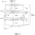
- Figure 2 displays a prior art schematic of a twin compliant joint structure 20.
- three discs A, B, C which are coupled together using compliant joints 22 and 24, such that a first compliant joint 22 links disc A to disc B, and a second compliant joint 24 connects disc B to disc C.
- the two compliant joints are angled relative to each other, such that they are rotated by 90° relative to each other.
- This configuration of a section allows for a contraction/extension along the lines A-A by manipulation of the compliant joints between discs B and C, whilst movement of the joint can be made along the lines B-B by manipulation of the compliant joint between discs A and B.
- Manipulation of the joint can be done by the movement of cables or actuators which are connected to the discs.
- FIG. 3A and 3B Examples of a section of a prior art continuum section for use in a robot is shown in Figure 3A and 3B .
- the multiple discs that form the section are linked by either alternating short and long elastomeric joints.
- the different length of the joints provides different stiffness for the sections, so the short sections bend less than the long sections.
- thin and thick section or thin-thin-thick-thick joints, which have the same length have also been used as shown in Figures 3C and 3D .
- An improvement to using these alternating thick or thin interconnecting sections between the discs can be achieved by allowing the stiffness to be adjusted along the length of the section. This is done by separating the length of the continuum section into three or more segments, such that they form at least a tip segment, a middle segment and a base segment. Each of these separate segments is provided with disc interconnects having different stiffness levels.
- the base segment has a wide interconnect between the discs in the base segment providing it with greater degree of rigidity.
- the middle section may be provided with disc interconnects of medium thicknesses. Whilst the tip segment is then provided with the narrowest interconnect between the discs.
- interconnects can either be of a single piece construction as is presented in Figure 4A .
- the interconnects may be formed of a number of parts having a standard thickness. Therefore, in order to achieve the varying thickness of the segments the interconnects can be added together such that the base segment has three interconnect parts coupled together to form a full interconnect structure, as presented in Figure 4B .
- the middle segment may have two interconnect parts coupled together to form the complete interconnect.
- the tip section having the lowest stiffness may only feature a single interconnect part. However, as the person skilled in the art will appreciate, this could be any suitable number of interconnect parts for each segment.
- Each of the segments can be bent in 2 degree-of-freedom.
- the segment has two interconnecting stages per segment, however, as shown in Figure 5 it is possible to achieve the same effect, for a single degree of freedom joint, with only a single interconnect forming each segment.
- the interconnect parts can either be a single unit ( Figure 5A ) or can be formed from a number of interconnect parts coupled together ( Figure 5B ), as described above.
- the base segment has the highest stiffness and may feature a wide interconnect section, or a greater number of interconnect parts.
- the middle segment being narrower or having a smaller number of interconnect parts.
- the tip section is narrower than the other sections or features the fewest number of interconnect parts.
- An alternative embodiment of this disclosure is that rather than changing thickness or stiffness of the interconnects is to provide walls for the discs and interconnects, which form the three separate segments that form the complete section that forms a part of a continuum arm.
- the wall portions for each of these separate segments are provided with a different stiffness, such that the base segment is stiffer than the middle, which is in turn stiffer than the tip.
- FIGs 6A and 6B An example of this is shown in Figures 6A and 6B .
- the materials for each of these walls are the same, and the wall sections are of different thickness such that the base section features a wide wall section, the middle segment having a medium wall thickness, and a tip section, which has a thin wall section.
- Suitable materials for the wall section may be elastic nitinol, spring steel. Alternatively, plastics or rubber materials could be used.
- the wall sections can be made from materials having different stiffness levels, such that the stiffness of the wall sections decreases in these segments of the section from base to tip.
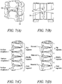
- FIG. 7A An alternative embodiment utilises revolute and compliant joints integrated into a single section and to adjust the stiffness along the longitudinal axis.
- FIG 7A An example of such a single joint is shown in Figure 7A .
- the single component is shown having a compliant joint part 72 and the rigid revolute joint 74.
- the stiffness of the compliant joint is constant, whilst the revolute joint stiffness can be varied.
- Figure 7B An example of this as in the present disclosure is shown in Figure 7B .
- This figure presents an example in which three of these rigid revolute and compliant joints form a single joint section.
- Each of these joint sections are formed having a base segment, middle segment and tip segment.
- the revolute joints between the sections are provided with joints having different surface roughness or being made of different materials.
- varying the surface roughness of the joints means that the pliability of the joints can be varied, which varies the stiffness of the joints.
- the base segment has the greatest surface roughness, so that this joint is the stiffest.
- the middle segment has a medium surface roughness and thus forming a middle stiffness joint.
- the tip segment has the lowest surface roughness and as such forms the least stiff joint.
- the reference to the surface roughness and the stiffness of the joints are when compared to each of the other joints.
- the surface roughness of the middle segment may have 10-99% of the surface roughness of base segment.
- the tip segment may have 10-99% of the surface roughness of the middle segment.
- This roughness difference may be in the range of about 10-75% for both the base to middle section and then again for the middle to the tip segments respectively.
- An alternative to using the joints having different surface roughness is to have the surface roughness the same, but instead to have different material for the disc. Examples of materials that could be employed are titanium 64 alloy (105-120 GPa), aluminium (69 GPA), steel (200 GPa), tungsten (400 GPa), silicon carbide (450 GPz). Alternatively, materials such as nylon (4 GPa), PET (2 GPa) or carbon reinforced plastics (50 GPa) could be considered for devices requiring less rigidity/stiffness. This leads to different levels of friction along the longitudinal axis, thus allowing the segment stiffness to be adjusted along the longitudinal axis.
- the continuum robot can have sections that curve with a circular shape when bent, and other bending shapes, such as quadratic curves. As such, this would provide the robot with better accessibility when navigating within confined spaces, or in situations where extreme control of the arm is required.
- Continuum robots featuring sections as described above could include being deployed into an aero engine gas path via a borescope port in order to perform precise repair and inspection activities. This could include accurate deployment of a grinding or deposition tool, or a nondestructive testing end effector such as an ultrasonic array or an eddy current probe. Other accurate inspection and or repair activities could be performed in confined environments such as industrial gas turbines, wind turbines or in key hole surgery for example.
- these sections are of set design, they can be adjusted on site to improve the performance of the robot arm.
- stiffening components can be added in appropriate places.
- the stiffening components can be added to a section formed of three or more segments, in which the joints have the same stiffness to produce a higher stiffness base than the middle, which is again higher than the tip, as in the other embodiments of this disclosure.
- the stiffening could be done through the addition of struts or through the addition of a sleeve of a certain thickness over a segment to adjust the stiffness of a segment.
- These segments or sleeves can be made from thermoplastic materials, shape memory alloys and/or shape memory polymers.
- the stiffening components can be used to reduce the stiffness of the section.
- the stiffening components can be made from materials such as shape memory alloys or current/heat activated materials or other materials that will be apparent to the person skilled in the art. The use of sleeves having different stiffness values could be used.
Landscapes
- Engineering & Computer Science (AREA)
- Robotics (AREA)
- Health & Medical Sciences (AREA)
- Mechanical Engineering (AREA)
- Life Sciences & Earth Sciences (AREA)
- Surgery (AREA)
- Heart & Thoracic Surgery (AREA)
- Biomedical Technology (AREA)
- Nuclear Medicine, Radiotherapy & Molecular Imaging (AREA)
- Medical Informatics (AREA)
- Molecular Biology (AREA)
- Animal Behavior & Ethology (AREA)
- General Health & Medical Sciences (AREA)
- Public Health (AREA)
- Veterinary Medicine (AREA)
- Manipulator (AREA)
Abstract
Description
- The invention relates to a continuum robot in particular for the design of an arm section of a continuum robot. This section can be part or a number of sections that form a full length arm that is capable of the inspection or repair of a component in a confined or dangerous environment.
- The use of robotics in manufacture, inspection and repair of complex structures is growing as these devices are able to access points that humans are unable to access. In order to perform such tasks there are a large number of robot designs and configurations, which are desirable for different purposes. In particular, snake arm or continuum robots are of particular interest. These continuum robots have numerous degrees of freedom that allow them to be particularly suited to accessing confined spaces unlike conventional rigid link robots. This allows them to be used for a wide range of purposes from surgery to in-situ repair of aero engines.
- Continuum robots generally consist of several independently controlled sections, with each section having one or two degrees-of-freedom which allows them to be easily manipulated. Each element of the sections is connected by rigid or compliant joints, which can be manipulated by pulling cables or adjusting pneumatic or hydraulic actuators; thus, allowing them to be articulated to different targeted orientations. One of the most common designs of continuum robots consists of using rigidly linked sections coupled together using revolute/universal/spherical (R/U/S) joints. There are, however, issues with the use of such systems; this is because of the difficulty in running a delivery tube with a diameter close to the inner diameter of the arm through the R/U/S joint. The issue is the result of the bending radius of the joint being small. This small radius can result in a kink being formed in the delivery tube, which can block the functioning of the tool or the delivery of material along the tube. In order to overcome this, a continuum section can feature an elastomer section between the rigid links; this is used to distribute the bend evenly over the whole length of the section. Consequently, use of an elastomer section allows for a more continuous curvature, which allows for the delivery tube to run through the middle of the robot arm. Thus, by employing elastomer materials within the sections of a continuum robot allows the robot's arm to have better bending capability, when compared to a rigid-joint continuum arm.
- One of the issues, however, of this type of robot is that when controlling the robot's arm using a kinematic model is that sections are considered as circular curves. In this case the kinematic model provides a means of controlling/determining the motion of multiple linked bodies. However, physical tests demonstrate that the continuum sections do not bend with a continuous and circular radius of curvature. Therefore, the discrepancy between the model and the actual shape of the arm can cause considerable amounts of positional errors for the robot. Consequently, there is a need to make the continuum section to better match circular curvature, such that the control of the continuum robot is more reliable.
- According to a first aspect there is provided a continuum arm robot section, in which the section comprises at least three segments, featuring a base, at least one middle segment and a tip segment, with each segment corresponding to at least one interconnecting portion between pairs of neighbouring discs that form a backbone of the section of the continuum arm robot, wherein the base segment having a greater stiffness than the at least one middle segment and tip segment and the at least one middle segment having a greater stiffness than the tip segment.
- By employing the teachings of the disclosure, the continuum robot can have sections that curve with a circular shape when bent, and also be adapted to form other bending shapes, such as quadratic curves. As such, this would provide the robot with better accessibility when navigating within confined spaces, or in situations where extreme control of the arm is required. Furthermore, as these sections are of set design, they can be adjusted on site to improve the performance of the robot arm.
- Each segment may be made from a compliant and revolute joint pair.
- The stiffness of the joints may be determined by the surface roughness of the revolute joint.
- The stiffness of the joints may be determined by the material of the discs within the revolute joints.
- The segments may be made from non-constant stiffness joints comprising discs that are separated by interconnecting portions having 2-degrees-of-freedom or 1 -degree-of-freedom.
- The interconnecting portions may be of varying thickness, with the base segment being the thickest interconnect portion and having the stiffest section, the middle segment having a medium thickness interconnecting portion with middle stiffness, and the tip segment having the thinnest interconnect portion and has the lowest stiffness.
- The interconnecting sections may be made from one or more metal materials such as titanium, aluminium, steel, tungsten, and/or silicon carbide.
- The interconnecting sections may be made from one or more non-metal materials such as nylon, Polyethylene terephthalate (PET) or carbon reinforced plastics.
- The segments may have wall sections surrounding the discs and interconnect portions.
- The wall sections may have different thicknesses substantially corresponding to the stiffness of each of the segments.
- The wall sections may be made of materials having different stiffness profiles that correspond to the different stiffness of each of the segments.
- At least one sleeve may be provided around a segment in order to adjust the stiffness of said section.
- The sleeve sections may be made from one or more of thermoplastic materials, shape memory alloys and shape memory polymers.
- At least one stiffening member may be provided on a segment in order to adjust the stiffness of said section.
- The stiffening members may be made from one or more of thermoplastic materials, shape memory alloys and shape memory polymers.
- According to a second aspect there is provided a continuum robot having one or more arms, each arm comprising at least one continuum robot arm section as claimed in any preceding claim.
- The continuum robot may be used in the inspection and/or repair of a gas turbine engine.
- According to a third aspect there is provided a method of adjusting the stiffness of a continuum arm section featuring a base, at least one middle segment and a tip segment, with each segment corresponding to at least one interconnecting portion between pairs of neighbouring discs that form a backbone of the section of the continuum arm robot, the method comprising the steps of: applying a first stiffening component to a segment; then applying a second stiffening component to a different segment, such that the first stiffening component results in the base segment having a greater stiffness than the middle segment, and the second stiffening component results in the middle segment having lower stiffness than the base segment, but higher than the tip segment.
- The applying of the first stiffening component and/or the applying the second stiffening component to a different segment may comprise adding a sleeve over an outer surface of the segment, or inserting stiffening struts.
- In this text a continuum robot is a hyper-redundant robot having a large or infinite number of degrees of freedom. These robots act as a continuously curving manipulator that is self-supporting. In order to fulfil these requirements, the robot is made from individual sections, each of which are controlled by different sets of tendons. An example of such a continuum robot is shown in
Figure 1 . The continuum robot has two sections; afirst section 12 and asecond section 14. Thefirst section 12 is controlled bycables 13, whilst thesecond section 14 is controlled bycables 15. The cables in continuum arm robots are constrained within the holes of thedisk components 11. By pullingtendons 16, each of the sections are able to move relative to each other such that the robot can be manipulated. The movement of the cables is actuated by motor/artificial muscle. - The skilled person will appreciate that except where mutually exclusive, a feature described in relation to any one of the above aspects may be applied mutatis mutandis to any other aspect. Furthermore, except where mutually exclusive any feature described herein may be applied to any aspect and/or combined with any other feature described herein.
- Embodiments will now be described by way of example only, with reference to the Figures, in which:
-
Figure 1 is a prior art example of a part of a continuum arm robot featuring two individual arm sections; -
Figure 2 is a prior art example of a simple compliant joint structure; -
Figures 3A-3D are a prior art examples of a continuum section for use in a continuum arm robot; -
Figures 4A-B present two embodiments of a continuum section having a two-degrees-of-freedom as part of the present disclosure;Figure 4A presents an example of the disclosure using a single piece interconnect,Figure 4B presents an example of the disclosure wherein the interconnect is formed from a number of interconnect parts; -
Figures 5A-B presents two embodiments of a continuum section having a single-degree-of-freedom as part of the present disclosure;Figure 5A presents an example of the disclosure using a single piece interconnect,Figure 5B presents an example of the disclosure wherein the interconnect is formed from a number of interconnect parts; -
Figures 6A-B presents an embodiment of a continuum section having a two-degrees-of-freedom of the present disclosure, wherein a wall section is provided for each of the separate segments;Figure 6A presents an outer view of the embodiment, whilstFigure 6B presents a cut-away view of the present disclosure; -
Figures 7A-D present two embodiment of a continuum section comprising rigid revolute joints as well as compliant joints;Figure 7A presents a cut away of a single segment of such a joint, whilstFigure 7B presents an outside view of the joint structure;Figures 7C presents an embodiment of the present disclosure wherein the revolute joints have different surface roughness; andFigure 7D presents an embodiment of the present disclosure wherein the revolute joints have different materials having differing materials of the discs. - Aspects and embodiments of the present disclosure will now be discussed with reference to the corresponding drawings. Other aspects and embodiments will be apparent to those skilled in the art.
-
Figure 2 displays a prior art schematic of a twin compliantjoint structure 20. In this there are three discs (A, B, C) which are coupled together usingcompliant joints - Examples of a section of a prior art continuum section for use in a robot is shown in
Figure 3A and 3B . Here the multiple discs that form the section are linked by either alternating short and long elastomeric joints. The different length of the joints provides different stiffness for the sections, so the short sections bend less than the long sections. Alternatively, thin and thick section or thin-thin-thick-thick joints, which have the same length, have also been used as shown inFigures 3C and 3D . This again results in each segment of the section having certain stiffness with the thicker sections being stiffer than the thinner sections. These do not overcome the issues presented above that the radius of curvature is non-ideal, and as such can lead to issues with the delivery tube that runs through the centre of the joint sections. - An improvement to using these alternating thick or thin interconnecting sections between the discs can be achieved by allowing the stiffness to be adjusted along the length of the section. This is done by separating the length of the continuum section into three or more segments, such that they form at least a tip segment, a middle segment and a base segment. Each of these separate segments is provided with disc interconnects having different stiffness levels. To achieve this, the base segment has a wide interconnect between the discs in the base segment providing it with greater degree of rigidity. The middle section may be provided with disc interconnects of medium thicknesses. Whilst the tip segment is then provided with the narrowest interconnect between the discs. By having a wide interconnect at the base, with progressively thinner sections for the middle and the tip segments provides these three segments with different levels of stiffness. With the base having the highest level of stiffness the base will prevent the section from kinking at the start allowing for a tube to be easily contained within it. These interconnects can either be of a single piece construction as is presented in
Figure 4A . Alternatively, the interconnects may be formed of a number of parts having a standard thickness. Therefore, in order to achieve the varying thickness of the segments the interconnects can be added together such that the base segment has three interconnect parts coupled together to form a full interconnect structure, as presented inFigure 4B . The middle segment may have two interconnect parts coupled together to form the complete interconnect. The tip section having the lowest stiffness may only feature a single interconnect part. However, as the person skilled in the art will appreciate, this could be any suitable number of interconnect parts for each segment. Each of the segments can be bent in 2 degree-of-freedom. - In the above example the segment has two interconnecting stages per segment, however, as shown in
Figure 5 it is possible to achieve the same effect, for a single degree of freedom joint, with only a single interconnect forming each segment. In this case the interconnect parts can either be a single unit (Figure 5A ) or can be formed from a number of interconnect parts coupled together (Figure 5B ), as described above. In this case the base segment has the highest stiffness and may feature a wide interconnect section, or a greater number of interconnect parts. The middle segment being narrower or having a smaller number of interconnect parts. Finally, the tip section is narrower than the other sections or features the fewest number of interconnect parts. - Although the embodiment has been presented in terms of thickness of the interconnects, similar effects could also be produced by using materials having different stiffness properties. This could be achieved using the same thickness interconnect, but with the interconnect being made using a material that has a greater level of stiffness, than the middle segment's interconnects, which in turn is greater than that of the interconnect in the tip segment. Examples of such materials that could be employed are titanium 64 alloy (105-120 GPa), aluminium (69 GPA), steel (200 GPa), tungsten (400 GPa), silicon carbide (450 GPz). Alternatively, materials such as nylon (4 GPa), PET (2 GPa) or carbon reinforced plastics (50 GPa) could be considered for devices requiring less rigidity/stiffness.
- An alternative embodiment of this disclosure is that rather than changing thickness or stiffness of the interconnects is to provide walls for the discs and interconnects, which form the three separate segments that form the complete section that forms a part of a continuum arm. The wall portions for each of these separate segments are provided with a different stiffness, such that the base segment is stiffer than the middle, which is in turn stiffer than the tip. An example of this is shown in
Figures 6A and 6B . In this the materials for each of these walls are the same, and the wall sections are of different thickness such that the base section features a wide wall section, the middle segment having a medium wall thickness, and a tip section, which has a thin wall section. Suitable materials for the wall section may be elastic nitinol, spring steel. Alternatively, plastics or rubber materials could be used. The wall sections can be made from materials having different stiffness levels, such that the stiffness of the wall sections decreases in these segments of the section from base to tip. - An alternative embodiment utilises revolute and compliant joints integrated into a single section and to adjust the stiffness along the longitudinal axis. An example of such a single joint is shown in
Figure 7A . The single component is shown having a compliantjoint part 72 and the rigid revolute joint 74. In this embodiment, along the longitudinal axis the stiffness of the compliant joint is constant, whilst the revolute joint stiffness can be varied. By combining these revolute and compliant joint segments a section be formed. An example of this as in the present disclosure is shown inFigure 7B . This figure presents an example in which three of these rigid revolute and compliant joints form a single joint section. Each of these joint sections are formed having a base segment, middle segment and tip segment. In this the revolute joints between the sections are provided with joints having different surface roughness or being made of different materials. By varying the surface roughness of the joints means that the pliability of the joints can be varied, which varies the stiffness of the joints. In this disclosure the base segment has the greatest surface roughness, so that this joint is the stiffest. The middle segment has a medium surface roughness and thus forming a middle stiffness joint. The tip segment has the lowest surface roughness and as such forms the least stiff joint. The reference to the surface roughness and the stiffness of the joints are when compared to each of the other joints. For example, the surface roughness of the middle segment may have 10-99% of the surface roughness of base segment. The tip segment may have 10-99% of the surface roughness of the middle segment. This roughness difference may be in the range of about 10-75% for both the base to middle section and then again for the middle to the tip segments respectively. An alternative to using the joints having different surface roughness, is to have the surface roughness the same, but instead to have different material for the disc. Examples of materials that could be employed are titanium 64 alloy (105-120 GPa), aluminium (69 GPA), steel (200 GPa), tungsten (400 GPa), silicon carbide (450 GPz). Alternatively, materials such as nylon (4 GPa), PET (2 GPa) or carbon reinforced plastics (50 GPa) could be considered for devices requiring less rigidity/stiffness. This leads to different levels of friction along the longitudinal axis, thus allowing the segment stiffness to be adjusted along the longitudinal axis. - By employing the teachings of the disclosure, the continuum robot can have sections that curve with a circular shape when bent, and other bending shapes, such as quadratic curves. As such, this would provide the robot with better accessibility when navigating within confined spaces, or in situations where extreme control of the arm is required. Continuum robots featuring sections as described above could include being deployed into an aero engine gas path via a borescope port in order to perform precise repair and inspection activities. This could include accurate deployment of a grinding or deposition tool, or a nondestructive testing end effector such as an ultrasonic array or an eddy current probe. Other accurate inspection and or repair activities could be performed in confined environments such as industrial gas turbines, wind turbines or in key hole surgery for example. Furthermore, as these sections are of set design, they can be adjusted on site to improve the performance of the robot arm.
- Any of the embodiments discussed above have the benefit that if due to aging or damage the curvature of a section no longer matches that of a circle then stiffening components can be added in appropriate places. Alternatively, the stiffening components can be added to a section formed of three or more segments, in which the joints have the same stiffness to produce a higher stiffness base than the middle, which is again higher than the tip, as in the other embodiments of this disclosure. For example, the stiffening could be done through the addition of struts or through the addition of a sleeve of a certain thickness over a segment to adjust the stiffness of a segment. These segments or sleeves can be made from thermoplastic materials, shape memory alloys and/or shape memory polymers. Alternatively, if the stiffness is too great the robot arm sections do not closely resemble the curvature of a circle, then removal of the stiffening components can be used to reduce the stiffness of the section. Such a design allows for a generic system to be manufactured, but the additional stiffening components allows the robot arm to be used in a number of environments with customised stiffness for each of these sections. Potentially the stiffening components can be made from materials such as shape memory alloys or current/heat activated materials or other materials that will be apparent to the person skilled in the art. The use of sleeves having different stiffness values could be used. This could work for example on sections all having the same stiffness values, such that a sleeve having a highest stiffness is provided around the base segment, a sleeve having less stiffness is provided around the middle segment and a sleeve with the lowest stiffness is provided for the tip segment.
- Although the embodiments have been described having three segments the invention is not limited to this. More segments can be added provided that the stiffness decreases from the base of the section to the tip. By using more segments, the control of the curvature may be greater for the trade-off of having a more complex component.
- It will be understood that the invention is not limited to the embodiments above-described and various modifications and improvements can be made without departing from the concepts described herein. Except where mutually exclusive, any of the features may be employed separately or in combination with any other features and the disclosure extends to and includes all combinations and subcombinations of one or more features described herein.
Claims (15)
- A continuum arm robot section, in which the section comprises at least three segments, featuring a base, at least one middle segment and a tip segment, with each segment corresponding to at least one interconnecting portion between pairs of neighbouring discs that form a backbone of the section of the continuum arm robot, wherein the base segment having a greater stiffness than the at least one middle segment and tip segment and the at least one middle segment having a greater stiffness than the tip segment.
- The continuum arm robot section as claimed in claim 1, wherein each segment is made from a compliant and revolute joint pair.
- The continuum arm robot section as claimed in claim 2, wherein the stiffness of the joints is determined by the surface roughness of the revolute joint.
- The continuum arm robot section as claimed in claim 2 or 3, wherein the stiffness of the joints is determined by the material of the discs within the revolute joints.
- The continuum arm robot section as claimed in claim 1, wherein the segments are made from non-constant stiffness joints comprising discs that are separated by interconnecting portions having 2-degrees-of-freedom or 1-degree-of-freedom.
- The continuum arm robot section as claimed in claim 5, wherein the interconnecting portions are of varying thickness, with the base segment being the thickest interconnect portion and having the stiffest section, the middle segment having a medium thickness interconnecting portion with middle stiffness, and the tip segment having the thinnest interconnect portion and has the lowest stiffness.
- The continuum arm robot section as claimed in claim 5 or 6, wherein the segments have wall sections surrounding the discs and interconnect portions.
- The continuum arm robot section as claimed in claim 7, wherein the wall sections have different thicknesses substantially corresponding to the stiffness of each of the segments.
- The continuum arm robot section as claimed in claim 8, wherein the wall sections are made of materials having different stiffness profiles that correspond to the different stiffness of each of the segments.
- The continuum arm robot section as claimed in any preceding claim, wherein at least one sleeve is provided around a segment in order to adjust the stiffness of said section.
- The continuum arm robot section as claimed in any preceding claim, wherein at least one stiffening member is provided on a segment in order to adjust the stiffness of said section.
- A continuum robot having one or more arms, each arm comprising at least one continuum robot arm section as claimed in any preceding claim.
- The continuum robot as claimed in claim 12 for use in the inspection and/or repair of a gas turbine engine.
- A method of adjusting the stiffness of a continuum arm section featuring a base, at least one middle segment and a tip segment, with each segment corresponding to at least one interconnecting portion between pairs of neighbouring discs that form a backbone of the section of the continuum arm robot, the method comprising the steps of:applying a first stiffening component to a segment; thenapplying a second stiffening component to a different segment, such that the first stiffening component results in the base segment having a greater stiffness than the middle segment, and the second stiffening component results in the middle segment having lower stiffness than the base segment, but higher than the tip segment.
- The method of claim 14, wherein the applying of the first stiffening component and/or the applying the second stiffening component into a different segment comprises adding a sleeve over an outer surface of the segment or inserting stiffening struts.
Applications Claiming Priority (1)
| Application Number | Priority Date | Filing Date | Title |
|---|---|---|---|
| GBGB1820398.4A GB201820398D0 (en) | 2018-12-14 | 2018-12-14 | Continuum robot |
Publications (2)
| Publication Number | Publication Date |
|---|---|
| EP3666475A1 true EP3666475A1 (en) | 2020-06-17 |
| EP3666475B1 EP3666475B1 (en) | 2023-08-09 |
Family
ID=65147211
Family Applications (1)
| Application Number | Title | Priority Date | Filing Date |
|---|---|---|---|
| EP19212242.2A Active EP3666475B1 (en) | 2018-12-14 | 2019-11-28 | Continuum robot |
Country Status (5)
| Country | Link |
|---|---|
| US (1) | US20200188042A1 (en) |
| EP (1) | EP3666475B1 (en) |
| CN (1) | CN111319033B (en) |
| GB (1) | GB201820398D0 (en) |
| SG (1) | SG10201911510YA (en) |
Cited By (1)
| Publication number | Priority date | Publication date | Assignee | Title |
|---|---|---|---|---|
| CN112428298A (en) * | 2020-11-17 | 2021-03-02 | 中国科学院宁波材料技术与工程研究所 | Soft robot arm and control system thereof |
Families Citing this family (23)
| Publication number | Priority date | Publication date | Assignee | Title |
|---|---|---|---|---|
| CN109774896A (en) * | 2019-01-31 | 2019-05-21 | 上海海洋大学 | Bionic sea snake for marine ranch monitoring |
| CN111588470B (en) * | 2020-05-18 | 2023-04-07 | 上海交通大学 | Omnidirectional special-shaped bent continuum flexible mechanical arm for intracavity interventional diagnosis and treatment |
| US12318156B2 (en) * | 2020-05-29 | 2025-06-03 | Virginia Tech Intellectual Properties, Inc. | Extensible continuum manipulator |
| US20230225758A1 (en) * | 2020-06-30 | 2023-07-20 | Beijing Surgerii Technology Co., Ltd. | Continuum instrument and surgical robot |
| CN115605139B (en) * | 2020-06-30 | 2024-07-05 | 北京术锐机器人股份有限公司 | Continuum instruments and surgical robots |
| CN113618775A (en) * | 2021-08-05 | 2021-11-09 | 西安交通大学 | Continuum robot joint and continuum robot |
| CN113752253B (en) * | 2021-08-16 | 2022-11-11 | 常州大学 | A Parameter Optimization Method for Continuum Robots |
| CN113787503B (en) * | 2021-08-27 | 2023-05-12 | 华中科技大学 | Continuum robot |
| US11787069B2 (en) | 2021-11-01 | 2023-10-17 | Oliver Crispin Robotics Limited | Insertion tool with flexible spine |
| CN116269794B (en) * | 2021-12-09 | 2026-02-17 | 北京术锐机器人股份有限公司 | Interlocking continuum structures and surgical robots |
| CN116269792B (en) * | 2021-12-09 | 2026-02-17 | 北京术锐机器人股份有限公司 | Continuous instruments and surgical robots with receiving channels |
| CN116269795B (en) * | 2021-12-09 | 2026-01-02 | 北京术锐机器人股份有限公司 | Continuous instruments and surgical robots with varying amounts of flexible bone structure |
| JP7778311B2 (en) | 2022-02-02 | 2025-12-02 | 三菱重工業株式会社 | Inspection cable guide mechanism, drive device, inspection cable insertion jig, and gas turbine inspection system equipped with these |
| JP7734918B2 (en) | 2022-02-02 | 2025-09-08 | 三菱重工業株式会社 | Control device, inspection system, control method, and program |
| CN115414126B (en) * | 2022-09-01 | 2024-09-24 | 山东大学 | Continuum robot |
| CN115556140B (en) * | 2022-09-29 | 2025-09-02 | 西安交通大学 | A bearing-type double-core continuum robot |
| CN115847389B (en) * | 2022-12-20 | 2025-09-09 | 北方工业大学 | Rigidity control and compensation method for continuum robot |
| DE102023108492A1 (en) | 2023-04-03 | 2024-10-10 | Deutsches Zentrum für Luft- und Raumfahrt e.V. | Robotic actuator |
| CN116394231B (en) * | 2023-05-19 | 2026-02-17 | 上海大学 | Continuum robot capable of realizing rigidity self-adjustment |
| CN117001710A (en) * | 2023-07-10 | 2023-11-07 | 浙江大学 | A large-angle, variable-stiffness flexible joint |
| CN116968007A (en) * | 2023-08-16 | 2023-10-31 | 上海大学 | Continuum robot |
| CN116968006A (en) * | 2023-08-16 | 2023-10-31 | 复旦大学 | A multi-stage continuum flexible manipulator execution system |
| CN117598648B (en) * | 2024-01-23 | 2024-04-09 | 浙江大学 | End effector for neuroendoscopic robotic surgery using compliant joints |
Citations (8)
| Publication number | Priority date | Publication date | Assignee | Title |
|---|---|---|---|---|
| US4753222A (en) * | 1985-12-13 | 1988-06-28 | Olympus Optical Co., Ltd. | Endoscopic flexible tube |
| US5005558A (en) * | 1988-05-16 | 1991-04-09 | Kabushiki Kaisha Toshiba | Endoscope |
| WO1995018311A1 (en) * | 1992-07-07 | 1995-07-06 | Wentz John D | Flexible positioning appendage |
| US20050131279A1 (en) * | 2003-04-01 | 2005-06-16 | Boston Scientific Scimed, Inc. | Articulation joint for video endoscope |
| US20060156851A1 (en) * | 2004-12-02 | 2006-07-20 | Jacobsen Stephen C | Mechanical serpentine device |
| US20080214897A1 (en) * | 2005-02-14 | 2008-09-04 | Shigeki Matsuo | Flexible Tube for Endoscope and Endoscope Device |
| US20140058364A1 (en) * | 2011-02-14 | 2014-02-27 | Intuitive Surgical Operations, Inc. | Jointed link structures exhibiting preferential bending, and related methods |
| US20160279789A1 (en) * | 2015-03-23 | 2016-09-29 | Rolls-Royce Plc | Flexible tools and apparatus for machining objects |
Family Cites Families (9)
| Publication number | Priority date | Publication date | Assignee | Title |
|---|---|---|---|---|
| US4900218A (en) * | 1983-04-07 | 1990-02-13 | Sutherland Ivan E | Robot arm structure |
| GB0309662D0 (en) * | 2003-04-28 | 2003-06-04 | Crampton Stephen | Robot CMM arm |
| US7276074B2 (en) * | 2004-01-21 | 2007-10-02 | Medtronic Xomed, Inc. | Angled tissue cutting instrument having variably positionable cutting window, indexing tool for use therewith and method of variably positioning a cutting window of an angled tissue cutting instrument |
| US20130090763A1 (en) * | 2008-01-25 | 2013-04-11 | The Trustees Of Columibia University In The City Of The City Of New York | Systems and methods for force sensing in a robot |
| US9539726B2 (en) * | 2012-04-20 | 2017-01-10 | Vanderbilt University | Systems and methods for safe compliant insertion and hybrid force/motion telemanipulation of continuum robots |
| GB201304572D0 (en) * | 2013-03-14 | 2013-05-01 | Rolls Royce Plc | Multi-jointed arm assembly |
| CN106002988B (en) * | 2016-06-15 | 2018-09-04 | 北京工业大学 | A kind of variable length bending Grazing condition machinery arm configuration |
| GB2557269B (en) * | 2016-12-02 | 2020-05-06 | Rolls Royce Plc | Hyper redundant robots |
| CN111317571B (en) * | 2018-12-13 | 2021-10-15 | 中国科学院沈阳自动化研究所 | A skeleton nesting controllable continuous deformation mechanism |
-
2018
- 2018-12-14 GB GBGB1820398.4A patent/GB201820398D0/en not_active Ceased
-
2019
- 2019-11-28 EP EP19212242.2A patent/EP3666475B1/en active Active
- 2019-12-02 SG SG10201911510YA patent/SG10201911510YA/en unknown
- 2019-12-03 US US16/701,383 patent/US20200188042A1/en not_active Abandoned
- 2019-12-13 CN CN201911282108.3A patent/CN111319033B/en active Active
Patent Citations (8)
| Publication number | Priority date | Publication date | Assignee | Title |
|---|---|---|---|---|
| US4753222A (en) * | 1985-12-13 | 1988-06-28 | Olympus Optical Co., Ltd. | Endoscopic flexible tube |
| US5005558A (en) * | 1988-05-16 | 1991-04-09 | Kabushiki Kaisha Toshiba | Endoscope |
| WO1995018311A1 (en) * | 1992-07-07 | 1995-07-06 | Wentz John D | Flexible positioning appendage |
| US20050131279A1 (en) * | 2003-04-01 | 2005-06-16 | Boston Scientific Scimed, Inc. | Articulation joint for video endoscope |
| US20060156851A1 (en) * | 2004-12-02 | 2006-07-20 | Jacobsen Stephen C | Mechanical serpentine device |
| US20080214897A1 (en) * | 2005-02-14 | 2008-09-04 | Shigeki Matsuo | Flexible Tube for Endoscope and Endoscope Device |
| US20140058364A1 (en) * | 2011-02-14 | 2014-02-27 | Intuitive Surgical Operations, Inc. | Jointed link structures exhibiting preferential bending, and related methods |
| US20160279789A1 (en) * | 2015-03-23 | 2016-09-29 | Rolls-Royce Plc | Flexible tools and apparatus for machining objects |
Cited By (2)
| Publication number | Priority date | Publication date | Assignee | Title |
|---|---|---|---|---|
| CN112428298A (en) * | 2020-11-17 | 2021-03-02 | 中国科学院宁波材料技术与工程研究所 | Soft robot arm and control system thereof |
| CN112428298B (en) * | 2020-11-17 | 2022-03-15 | 中国科学院宁波材料技术与工程研究所 | A software robot arm and its control system |
Also Published As
| Publication number | Publication date |
|---|---|
| CN111319033A (en) | 2020-06-23 |
| GB201820398D0 (en) | 2019-01-30 |
| EP3666475B1 (en) | 2023-08-09 |
| US20200188042A1 (en) | 2020-06-18 |
| SG10201911510YA (en) | 2020-07-29 |
| CN111319033B (en) | 2024-06-25 |
Similar Documents
| Publication | Publication Date | Title |
|---|---|---|
| EP3666475B1 (en) | Continuum robot | |
| US9814480B2 (en) | Forceps manipulator and forceps system comprising forceps manipulator | |
| Dong et al. | Development of a slender continuum robotic system for on-wing inspection/repair of gas turbine engines | |
| Tan et al. | Design, characterization and applications of a novel soft actuator driven by flexible shafts | |
| Lock et al. | Friction modeling in concentric tube robots | |
| US20090095112A1 (en) | Link Assembly With Defined Boundaries For A Snake Like Robot Arm | |
| Mazare et al. | Kinematic analysis and design of a 3-DOF translational parallel robot | |
| Dupont et al. | Torsional kinematic model for concentric tube robots | |
| JP2009522121A (en) | Robot arm | |
| Ma et al. | Modeling and experimental validation of a compliant underactuated parallel kinematic manipulator | |
| Kim et al. | Cable-movable rolling joint to expand workspace under high external load in a hyper-redundant manipulator | |
| Fraś et al. | Static modeling of multisection soft continuum manipulator for stiff-flop project | |
| JP7455261B2 (en) | link actuator | |
| CN107650120B (en) | Method for determining all singular configurations of 9-degree-of-freedom mechanical arm | |
| Kong et al. | Dexterity analysis and motion optimization of in-situ torsionally-steerable flexible surgical robots | |
| US20060243085A1 (en) | Spherical motion mechanism | |
| CN104260081A (en) | Three-degree-of-freedom driver and driving method | |
| Kim et al. | Design concept of hybrid instrument for laparoscopic surgery and its verification using scale model test | |
| US11865703B2 (en) | Flexible mechanical joint | |
| Kim et al. | Wave-shaped notched compliant joint with high rigidity | |
| HK40022055A (en) | Continuum robot | |
| HK40022055B (en) | Continuum robot | |
| JP2023092495A (en) | robot stiffness | |
| CN115847389A (en) | Rigidity control and compensation method of continuum robot | |
| JP2019209391A (en) | Rotation restriction mechanism and three-dimensional linear variable rigidity mechanism |
Legal Events
| Date | Code | Title | Description |
|---|---|---|---|
| PUAI | Public reference made under article 153(3) epc to a published international application that has entered the european phase |
Free format text: ORIGINAL CODE: 0009012 |
|
| STAA | Information on the status of an ep patent application or granted ep patent |
Free format text: STATUS: THE APPLICATION HAS BEEN PUBLISHED |
|
| AK | Designated contracting states |
Kind code of ref document: A1 Designated state(s): AL AT BE BG CH CY CZ DE DK EE ES FI FR GB GR HR HU IE IS IT LI LT LU LV MC MK MT NL NO PL PT RO RS SE SI SK SM TR |
|
| AX | Request for extension of the european patent |
Extension state: BA ME |
|
| REG | Reference to a national code |
Ref country code: HK Ref legal event code: DE Ref document number: 40022055 Country of ref document: HK |
|
| STAA | Information on the status of an ep patent application or granted ep patent |
Free format text: STATUS: REQUEST FOR EXAMINATION WAS MADE |
|
| 17P | Request for examination filed |
Effective date: 20201216 |
|
| RBV | Designated contracting states (corrected) |
Designated state(s): AL AT BE BG CH CY CZ DE DK EE ES FI FR GB GR HR HU IE IS IT LI LT LU LV MC MK MT NL NO PL PT RO RS SE SI SK SM TR |
|
| GRAP | Despatch of communication of intention to grant a patent |
Free format text: ORIGINAL CODE: EPIDOSNIGR1 |
|
| STAA | Information on the status of an ep patent application or granted ep patent |
Free format text: STATUS: GRANT OF PATENT IS INTENDED |
|
| INTG | Intention to grant announced |
Effective date: 20230331 |
|
| RIC1 | Information provided on ipc code assigned before grant |
Ipc: B25J 9/06 20060101AFI20230317BHEP |
|
| GRAS | Grant fee paid |
Free format text: ORIGINAL CODE: EPIDOSNIGR3 |
|
| GRAA | (expected) grant |
Free format text: ORIGINAL CODE: 0009210 |
|
| STAA | Information on the status of an ep patent application or granted ep patent |
Free format text: STATUS: THE PATENT HAS BEEN GRANTED |
|
| P01 | Opt-out of the competence of the unified patent court (upc) registered |
Effective date: 20230528 |
|
| AK | Designated contracting states |
Kind code of ref document: B1 Designated state(s): AL AT BE BG CH CY CZ DE DK EE ES FI FR GB GR HR HU IE IS IT LI LT LU LV MC MK MT NL NO PL PT RO RS SE SI SK SM TR |
|
| REG | Reference to a national code |
Ref country code: GB Ref legal event code: FG4D |
|
| REG | Reference to a national code |
Ref country code: CH Ref legal event code: EP |
|
| REG | Reference to a national code |
Ref country code: DE Ref legal event code: R096 Ref document number: 602019034474 Country of ref document: DE |
|
| REG | Reference to a national code |
Ref country code: IE Ref legal event code: FG4D |
|
| REG | Reference to a national code |
Ref country code: LT Ref legal event code: MG9D |
|
| REG | Reference to a national code |
Ref country code: NL Ref legal event code: MP Effective date: 20230809 |
|
| REG | Reference to a national code |
Ref country code: AT Ref legal event code: MK05 Ref document number: 1596964 Country of ref document: AT Kind code of ref document: T Effective date: 20230809 |
|
| PG25 | Lapsed in a contracting state [announced via postgrant information from national office to epo] |
Ref country code: GR Free format text: LAPSE BECAUSE OF FAILURE TO SUBMIT A TRANSLATION OF THE DESCRIPTION OR TO PAY THE FEE WITHIN THE PRESCRIBED TIME-LIMIT Effective date: 20231110 |
|
| PG25 | Lapsed in a contracting state [announced via postgrant information from national office to epo] |
Ref country code: IS Free format text: LAPSE BECAUSE OF FAILURE TO SUBMIT A TRANSLATION OF THE DESCRIPTION OR TO PAY THE FEE WITHIN THE PRESCRIBED TIME-LIMIT Effective date: 20231209 |
|
| PG25 | Lapsed in a contracting state [announced via postgrant information from national office to epo] |
Ref country code: SE Free format text: LAPSE BECAUSE OF FAILURE TO SUBMIT A TRANSLATION OF THE DESCRIPTION OR TO PAY THE FEE WITHIN THE PRESCRIBED TIME-LIMIT Effective date: 20230809 Ref country code: RS Free format text: LAPSE BECAUSE OF FAILURE TO SUBMIT A TRANSLATION OF THE DESCRIPTION OR TO PAY THE FEE WITHIN THE PRESCRIBED TIME-LIMIT Effective date: 20230809 Ref country code: PT Free format text: LAPSE BECAUSE OF FAILURE TO SUBMIT A TRANSLATION OF THE DESCRIPTION OR TO PAY THE FEE WITHIN THE PRESCRIBED TIME-LIMIT Effective date: 20231211 Ref country code: NO Free format text: LAPSE BECAUSE OF FAILURE TO SUBMIT A TRANSLATION OF THE DESCRIPTION OR TO PAY THE FEE WITHIN THE PRESCRIBED TIME-LIMIT Effective date: 20231109 Ref country code: NL Free format text: LAPSE BECAUSE OF FAILURE TO SUBMIT A TRANSLATION OF THE DESCRIPTION OR TO PAY THE FEE WITHIN THE PRESCRIBED TIME-LIMIT Effective date: 20230809 Ref country code: LV Free format text: LAPSE BECAUSE OF FAILURE TO SUBMIT A TRANSLATION OF THE DESCRIPTION OR TO PAY THE FEE WITHIN THE PRESCRIBED TIME-LIMIT Effective date: 20230809 Ref country code: LT Free format text: LAPSE BECAUSE OF FAILURE TO SUBMIT A TRANSLATION OF THE DESCRIPTION OR TO PAY THE FEE WITHIN THE PRESCRIBED TIME-LIMIT Effective date: 20230809 Ref country code: IS Free format text: LAPSE BECAUSE OF FAILURE TO SUBMIT A TRANSLATION OF THE DESCRIPTION OR TO PAY THE FEE WITHIN THE PRESCRIBED TIME-LIMIT Effective date: 20231209 Ref country code: HR Free format text: LAPSE BECAUSE OF FAILURE TO SUBMIT A TRANSLATION OF THE DESCRIPTION OR TO PAY THE FEE WITHIN THE PRESCRIBED TIME-LIMIT Effective date: 20230809 Ref country code: GR Free format text: LAPSE BECAUSE OF FAILURE TO SUBMIT A TRANSLATION OF THE DESCRIPTION OR TO PAY THE FEE WITHIN THE PRESCRIBED TIME-LIMIT Effective date: 20231110 Ref country code: FI Free format text: LAPSE BECAUSE OF FAILURE TO SUBMIT A TRANSLATION OF THE DESCRIPTION OR TO PAY THE FEE WITHIN THE PRESCRIBED TIME-LIMIT Effective date: 20230809 Ref country code: AT Free format text: LAPSE BECAUSE OF FAILURE TO SUBMIT A TRANSLATION OF THE DESCRIPTION OR TO PAY THE FEE WITHIN THE PRESCRIBED TIME-LIMIT Effective date: 20230809 |
|
| PG25 | Lapsed in a contracting state [announced via postgrant information from national office to epo] |
Ref country code: PL Free format text: LAPSE BECAUSE OF FAILURE TO SUBMIT A TRANSLATION OF THE DESCRIPTION OR TO PAY THE FEE WITHIN THE PRESCRIBED TIME-LIMIT Effective date: 20230809 |
|
| PG25 | Lapsed in a contracting state [announced via postgrant information from national office to epo] |
Ref country code: ES Free format text: LAPSE BECAUSE OF FAILURE TO SUBMIT A TRANSLATION OF THE DESCRIPTION OR TO PAY THE FEE WITHIN THE PRESCRIBED TIME-LIMIT Effective date: 20230809 |
|
| PG25 | Lapsed in a contracting state [announced via postgrant information from national office to epo] |
Ref country code: SM Free format text: LAPSE BECAUSE OF FAILURE TO SUBMIT A TRANSLATION OF THE DESCRIPTION OR TO PAY THE FEE WITHIN THE PRESCRIBED TIME-LIMIT Effective date: 20230809 Ref country code: RO Free format text: LAPSE BECAUSE OF FAILURE TO SUBMIT A TRANSLATION OF THE DESCRIPTION OR TO PAY THE FEE WITHIN THE PRESCRIBED TIME-LIMIT Effective date: 20230809 Ref country code: ES Free format text: LAPSE BECAUSE OF FAILURE TO SUBMIT A TRANSLATION OF THE DESCRIPTION OR TO PAY THE FEE WITHIN THE PRESCRIBED TIME-LIMIT Effective date: 20230809 Ref country code: EE Free format text: LAPSE BECAUSE OF FAILURE TO SUBMIT A TRANSLATION OF THE DESCRIPTION OR TO PAY THE FEE WITHIN THE PRESCRIBED TIME-LIMIT Effective date: 20230809 Ref country code: DK Free format text: LAPSE BECAUSE OF FAILURE TO SUBMIT A TRANSLATION OF THE DESCRIPTION OR TO PAY THE FEE WITHIN THE PRESCRIBED TIME-LIMIT Effective date: 20230809 Ref country code: CZ Free format text: LAPSE BECAUSE OF FAILURE TO SUBMIT A TRANSLATION OF THE DESCRIPTION OR TO PAY THE FEE WITHIN THE PRESCRIBED TIME-LIMIT Effective date: 20230809 Ref country code: SK Free format text: LAPSE BECAUSE OF FAILURE TO SUBMIT A TRANSLATION OF THE DESCRIPTION OR TO PAY THE FEE WITHIN THE PRESCRIBED TIME-LIMIT Effective date: 20230809 |
|
| REG | Reference to a national code |
Ref country code: DE Ref legal event code: R097 Ref document number: 602019034474 Country of ref document: DE |
|
| PG25 | Lapsed in a contracting state [announced via postgrant information from national office to epo] |
Ref country code: IT Free format text: LAPSE BECAUSE OF FAILURE TO SUBMIT A TRANSLATION OF THE DESCRIPTION OR TO PAY THE FEE WITHIN THE PRESCRIBED TIME-LIMIT Effective date: 20230809 |
|
| PLBE | No opposition filed within time limit |
Free format text: ORIGINAL CODE: 0009261 |
|
| STAA | Information on the status of an ep patent application or granted ep patent |
Free format text: STATUS: NO OPPOSITION FILED WITHIN TIME LIMIT |
|
| REG | Reference to a national code |
Ref country code: CH Ref legal event code: PL |
|
| PG25 | Lapsed in a contracting state [announced via postgrant information from national office to epo] |
Ref country code: MC Free format text: LAPSE BECAUSE OF FAILURE TO SUBMIT A TRANSLATION OF THE DESCRIPTION OR TO PAY THE FEE WITHIN THE PRESCRIBED TIME-LIMIT Effective date: 20230809 |
|
| PG25 | Lapsed in a contracting state [announced via postgrant information from national office to epo] |
Ref country code: LU Free format text: LAPSE BECAUSE OF NON-PAYMENT OF DUE FEES Effective date: 20231128 |
|
| 26N | No opposition filed |
Effective date: 20240513 |
|
| PG25 | Lapsed in a contracting state [announced via postgrant information from national office to epo] |
Ref country code: CH Free format text: LAPSE BECAUSE OF NON-PAYMENT OF DUE FEES Effective date: 20231130 |
|
| PG25 | Lapsed in a contracting state [announced via postgrant information from national office to epo] |
Ref country code: MC Free format text: LAPSE BECAUSE OF FAILURE TO SUBMIT A TRANSLATION OF THE DESCRIPTION OR TO PAY THE FEE WITHIN THE PRESCRIBED TIME-LIMIT Effective date: 20230809 Ref country code: LU Free format text: LAPSE BECAUSE OF NON-PAYMENT OF DUE FEES Effective date: 20231128 Ref country code: CH Free format text: LAPSE BECAUSE OF NON-PAYMENT OF DUE FEES Effective date: 20231130 Ref country code: SI Free format text: LAPSE BECAUSE OF FAILURE TO SUBMIT A TRANSLATION OF THE DESCRIPTION OR TO PAY THE FEE WITHIN THE PRESCRIBED TIME-LIMIT Effective date: 20230809 |
|
| REG | Reference to a national code |
Ref country code: BE Ref legal event code: MM Effective date: 20231130 |
|
| REG | Reference to a national code |
Ref country code: IE Ref legal event code: MM4A |
|
| PG25 | Lapsed in a contracting state [announced via postgrant information from national office to epo] |
Ref country code: IE Free format text: LAPSE BECAUSE OF NON-PAYMENT OF DUE FEES Effective date: 20231128 |
|
| PG25 | Lapsed in a contracting state [announced via postgrant information from national office to epo] |
Ref country code: BE Free format text: LAPSE BECAUSE OF NON-PAYMENT OF DUE FEES Effective date: 20231130 |
|
| PG25 | Lapsed in a contracting state [announced via postgrant information from national office to epo] |
Ref country code: IE Free format text: LAPSE BECAUSE OF NON-PAYMENT OF DUE FEES Effective date: 20231128 Ref country code: BE Free format text: LAPSE BECAUSE OF NON-PAYMENT OF DUE FEES Effective date: 20231130 |
|
| PG25 | Lapsed in a contracting state [announced via postgrant information from national office to epo] |
Ref country code: BG Free format text: LAPSE BECAUSE OF FAILURE TO SUBMIT A TRANSLATION OF THE DESCRIPTION OR TO PAY THE FEE WITHIN THE PRESCRIBED TIME-LIMIT Effective date: 20230809 |
|
| PG25 | Lapsed in a contracting state [announced via postgrant information from national office to epo] |
Ref country code: BG Free format text: LAPSE BECAUSE OF FAILURE TO SUBMIT A TRANSLATION OF THE DESCRIPTION OR TO PAY THE FEE WITHIN THE PRESCRIBED TIME-LIMIT Effective date: 20230809 |
|
| PG25 | Lapsed in a contracting state [announced via postgrant information from national office to epo] |
Ref country code: CY Free format text: LAPSE BECAUSE OF FAILURE TO SUBMIT A TRANSLATION OF THE DESCRIPTION OR TO PAY THE FEE WITHIN THE PRESCRIBED TIME-LIMIT; INVALID AB INITIO Effective date: 20191128 |
|
| PG25 | Lapsed in a contracting state [announced via postgrant information from national office to epo] |
Ref country code: HU Free format text: LAPSE BECAUSE OF FAILURE TO SUBMIT A TRANSLATION OF THE DESCRIPTION OR TO PAY THE FEE WITHIN THE PRESCRIBED TIME-LIMIT; INVALID AB INITIO Effective date: 20191128 |
|
| PG25 | Lapsed in a contracting state [announced via postgrant information from national office to epo] |
Ref country code: TR Free format text: LAPSE BECAUSE OF FAILURE TO SUBMIT A TRANSLATION OF THE DESCRIPTION OR TO PAY THE FEE WITHIN THE PRESCRIBED TIME-LIMIT Effective date: 20230809 |
|
| PGFP | Annual fee paid to national office [announced via postgrant information from national office to epo] |
Ref country code: DE Payment date: 20251126 Year of fee payment: 7 |
|
| PGFP | Annual fee paid to national office [announced via postgrant information from national office to epo] |
Ref country code: GB Payment date: 20251125 Year of fee payment: 7 |
|
| PGFP | Annual fee paid to national office [announced via postgrant information from national office to epo] |
Ref country code: FR Payment date: 20251124 Year of fee payment: 7 |