EP3666486A1 - Procédé de production de moules - Google Patents
Procédé de production de moules Download PDFInfo
- Publication number
- EP3666486A1 EP3666486A1 EP19215335.1A EP19215335A EP3666486A1 EP 3666486 A1 EP3666486 A1 EP 3666486A1 EP 19215335 A EP19215335 A EP 19215335A EP 3666486 A1 EP3666486 A1 EP 3666486A1
- Authority
- EP
- European Patent Office
- Prior art keywords
- monolithic solid
- construction direction
- mould
- moulding
- fixed
- Prior art date
- Legal status (The legal status is an assumption and is not a legal conclusion. Google has not performed a legal analysis and makes no representation as to the accuracy of the status listed.)
- Withdrawn
Links
Images
Classifications
-
- B—PERFORMING OPERATIONS; TRANSPORTING
- B29—WORKING OF PLASTICS; WORKING OF SUBSTANCES IN A PLASTIC STATE IN GENERAL
- B29C—SHAPING OR JOINING OF PLASTICS; SHAPING OF MATERIAL IN A PLASTIC STATE, NOT OTHERWISE PROVIDED FOR; AFTER-TREATMENT OF THE SHAPED PRODUCTS, e.g. REPAIRING
- B29C33/00—Moulds or cores; Details thereof or accessories therefor
- B29C33/38—Moulds or cores; Details thereof or accessories therefor characterised by the material or the manufacturing process
- B29C33/3842—Manufacturing moulds, e.g. shaping the mould surface by machining
-
- B—PERFORMING OPERATIONS; TRANSPORTING
- B33—ADDITIVE MANUFACTURING TECHNOLOGY
- B33Y—ADDITIVE MANUFACTURING, i.e. MANUFACTURING OF THREE-DIMENSIONAL [3D] OBJECTS BY ADDITIVE DEPOSITION, ADDITIVE AGGLOMERATION OR ADDITIVE LAYERING, e.g. BY 3D PRINTING, STEREOLITHOGRAPHY OR SELECTIVE LASER SINTERING
- B33Y80/00—Products made by additive manufacturing
-
- B—PERFORMING OPERATIONS; TRANSPORTING
- B33—ADDITIVE MANUFACTURING TECHNOLOGY
- B33Y—ADDITIVE MANUFACTURING, i.e. MANUFACTURING OF THREE-DIMENSIONAL [3D] OBJECTS BY ADDITIVE DEPOSITION, ADDITIVE AGGLOMERATION OR ADDITIVE LAYERING, e.g. BY 3D PRINTING, STEREOLITHOGRAPHY OR SELECTIVE LASER SINTERING
- B33Y10/00—Processes of additive manufacturing
-
- B—PERFORMING OPERATIONS; TRANSPORTING
- B29—WORKING OF PLASTICS; WORKING OF SUBSTANCES IN A PLASTIC STATE IN GENERAL
- B29C—SHAPING OR JOINING OF PLASTICS; SHAPING OF MATERIAL IN A PLASTIC STATE, NOT OTHERWISE PROVIDED FOR; AFTER-TREATMENT OF THE SHAPED PRODUCTS, e.g. REPAIRING
- B29C70/00—Shaping composites, i.e. plastics material comprising reinforcements, fillers or preformed parts, e.g. inserts
- B29C70/04—Shaping composites, i.e. plastics material comprising reinforcements, fillers or preformed parts, e.g. inserts comprising reinforcements only, e.g. self-reinforcing plastics
- B29C70/28—Shaping operations therefor
- B29C70/30—Shaping by lay-up, i.e. applying fibres, tape or broadsheet on a mould, former or core; Shaping by spray-up, i.e. spraying of fibres on a mould, former or core
- B29C70/38—Automated lay-up, e.g. using robots, laying filaments according to predetermined patterns
Definitions
- the invention relates to a method for the production of moulds, in particular for producing a mould configured for moulding a tool suitable for providing support and shape to a preform made of composite material intended to be subsequently processed, in particular laminated and cured.
- the mould produced by the method in question will define, substantially, a forming die provided, generally, with a complex shape, like, for example, a surface with a double curve.
- the relatively complex shape of the die will substantially correspond to a shape of the moulding tool, thus to a shape of the preform.
- the mould made can be usefully used in the aerospace industry and/or in the car industry, in particular in a clean room or another laminating shop, in an autoclave or another shop equipped for infusion, for the production of moulds or final parts made of CFRP (carbon fibre reinforced polymer), or GFRP (glass fibre reinforced polymers), or other fibre-reinforced materials.
- CFRP carbon fibre reinforced polymer
- GFRP glass fibre reinforced polymers
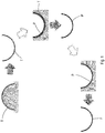
- Figure 1 shows the steps of a production cycle according to the prior art, in particular for the production of a product made of carbon fibre reinforced polymer (CFRP), that comprises, in sequence, a first moulding step for moulding a tool T, in particular made of carbon fibre reinforced polymer (CFRP), obtained in a mould or model 1', a second moulding step for moulding a preform P, in particular also made of a carbon fibre reinforced polymer (CFRP), obtained on the tool T positioned on a support frame 2', and a third step in which the (suitably laminated and cured) preform P is positioned on a processing template 3' where it can undergo finishing machining (for example CNC milling) to obtain the finished workpiece F.
- CFRP carbon fibre reinforced polymer
- One of the problems of the prior art is that of improving the production of the mould or model 1' usable as a die for moulding a moulding tool T that can in turn be used for forming a preform P.
- One object of the invention is to improve a solution that is an alternative to the problem of producing a mould or model that is usable as a die for moulding an object with a relatively curved shape.
- One advantage is to provide a method for producing moulds that are usable for laminating and polymerizing objects made of composite material, in particular a method for producing moulds by additive technique.
- One advantage is to enable a tool to be formed that is usable as a die for moulding a laminated preform provided with a relatively complex shape like, in particular, a sheet shape with a double curve.
- One advantage is to make available a mould that is constructionally simple and cheap and usable for forming a tool that can act as a die for moulding a laminated preform.
- One advantage is to make a mould configured for moulding a tool that is suitable for providing support and shape for a preform, in which the mould is relatively light but with excellent mechanical features.
- One advantage is to make a mould configured for moulding a tool that is suitable for providing support and shape for a preform, in which the mould has a hollow structure that is almost insensitive to pressure of an autoclave.
- One advantage is to make a mould configured for moulding a tool that is suitable for providing support and shape for a preform, in which the mould has surfaces with tilts comprised between ⁇ 45° without the need to use removable supports to make the mould.
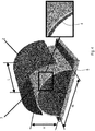
- a production method for producing a mould that is suitable for moulding a tool that is suitable for providing support and shape to a preform made of composite material comprises the step of forming a monolithic solid by an additive manufacturing technique in a construction direction, in which the monolithic solid comprises a sandwich structure of curved shape that extends between two end edges extending in length in the construction direction, the sandwich structure comprising an inner core that has a section with a corrugated profile.
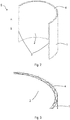
- the monolithic solid S may comprise, in particular, a sandwich structure comprising an outer surface 1, an inner surface 2 and an intermediate portion 4 acting as a connection core between the inner surface 2 and the outer surface 1.
- the sandwich structure may, in particular, extend with a curved shape that extends between two end edges 3 extending in length in the construction direction 5. The two end edges 3 may be far from one another.
- a section of the intermediate portion 4 according to a plane that is orthogonal to the construction direction 5 may have, as in the specific embodiment disclosed here, a corrugated profile.
- the corrugated profile may comprise, as in this specific embodiment, a regular sinusoidal profile.
- the monolithic solid may comprise, in particular (according to an embodiment that is not illustrated), two or more sections that are fixed (for example glued) together and are fixed to a support structure 6 (for example by structural bonding).
- the support structure 6 may comprise, in particular, a horizontal platform.
- a tilt of the outer surface 1 with respect to the construction direction 5 may be, in particular, comprised in the range ⁇ 45°.
- a tilt of the inner surface 2 with respect to the construction direction 5 may be, in particular, comprised in the range ⁇ 45°.
- the monolithic solid S may have, in particular, a width W greater than 1000 mm (millimetres), for example equal to 2000 ⁇ 1000 mm, and/or a length L greater than 1000 mm, for example the same as 2000 ⁇ 1000 mm, and/or a height H greater than 500 mm, for example the same as 1000 ⁇ 500 mm. It is nevertheless possible to provide other dimensions of the monolithic solid S.
- a production method comprises the step of forming the aforesaid monolithic solid S by the additive manufacturing technique (for example 3D moulding with polymeric material) in the construction direction 5.
- the additive manufacturing technique for example 3D moulding with polymeric material
- the production method may comprise, in particular, the step of fixing the two end edges 3 of the monolithic solid S to a support structure 6 in such a manner that the outer surface 1 faces upwards and is usable as a forming die for moulding an object T.
- the production method may comprise, in particular, the step of finishing the outer surface 1 by CNC machining, for example by machining that comprises milling.
- the production method may comprise, in particular, the step of covering the outer surface 1 with a layer 7 of pasty material, for example a pasty material of epoxy type.
- the production method may comprise, in particular, the step of curing (polymerizing and hardening) the aforesaid layer 7 of pasty material and finishing an outer surface of the aforesaid layer 7 by CNC machining, for example by machining that comprises milling.
- the production method may comprise, in particular, the step of moulding an object Z made of composite material using the outer surface 1 (possibly coated with the layer 7) as a forming die for forming the object Z.
- the object Z may comprise, in particular, a tool, for example made of a carbon fibre reinforced polymer (CFRP), intended to be positioned on a support frame and used as a die for moulding a preform, in particular also made of a carbon fibre reinforced polymer (CFRP).
- CFRP carbon fibre reinforced polymer
- the aforesaid preform (suitably laminated and cured) is positioned on a processing template where it can undergo finishing machining (for example CNC milling) to obtain a finished workpiece.
- finishing machining for example CNC milling
- the monolithic solid S (possibly covered with the layer 7) may be intended to act as a mould or model usable, in particular, as a die for moulding a moulding tool that may in turn be used for forming a preform (in particular a preform with a complex outer surface, for example a surface with a double curve).
- the preform may comprise, in particular, a laminated preform with a laminating method that may comprise, for example, a manual or automatic method (for example AFP, ATL).
- a laminating method may comprise, for example, a manual or automatic method (for example AFP, ATL).
- the polymerization temperature may be, in particular, below the heat deflection temperature under the weight of the material used for the construction of the tool (monolithic solid S).
- the production method may comprise, in particular, a method of 3D moulding by layers, for example using SEAM technology, to make the aforesaid hollow monolithic solid S, structured as a sandwich, comprising at least the outer surface 1, the inner surface 2, the two end edges 3, the intermediate portion 4 or connection core (of sinusoidal shape).
- the elements disclosed above are all connected integrally to one another and moulded in the construction direction 5.
- edges 3 of the 3D printed solid are fixed (glued) to the support structure 6 (platform) so as to obtain the outer surface 1 in the upper position facing upwards.
- the monolithic solid S is obtained in two or more sections that can be fixed integrally (glued) to one another and/or be fixed integrally (glued) to the support structure 6.
Landscapes
- Engineering & Computer Science (AREA)
- Manufacturing & Machinery (AREA)
- Chemical & Material Sciences (AREA)
- Materials Engineering (AREA)
- Mechanical Engineering (AREA)
- Moulds For Moulding Plastics Or The Like (AREA)
Applications Claiming Priority (1)
| Application Number | Priority Date | Filing Date | Title |
|---|---|---|---|
| IT102018000011093A IT201800011093A1 (it) | 2018-12-14 | 2018-12-14 | Metodo per la produzione di stampi |
Publications (1)
| Publication Number | Publication Date |
|---|---|
| EP3666486A1 true EP3666486A1 (fr) | 2020-06-17 |
Family
ID=65861622
Family Applications (1)
| Application Number | Title | Priority Date | Filing Date |
|---|---|---|---|
| EP19215335.1A Withdrawn EP3666486A1 (fr) | 2018-12-14 | 2019-12-11 | Procédé de production de moules |
Country Status (3)
| Country | Link |
|---|---|
| US (1) | US20200189150A1 (fr) |
| EP (1) | EP3666486A1 (fr) |
| IT (1) | IT201800011093A1 (fr) |
Citations (5)
| Publication number | Priority date | Publication date | Assignee | Title |
|---|---|---|---|---|
| US6112804A (en) * | 1995-10-31 | 2000-09-05 | Massachusetts Institute Of Technology | Tooling made by solid free form fabrication techniques having enhanced thermal properties |
| US20100314794A1 (en) * | 2009-06-15 | 2010-12-16 | The Boeing Company | Method and Apparatus for Rapidly Generating Aerospace Tools |
| US20110156304A1 (en) * | 2009-12-31 | 2011-06-30 | Bryant Walker | Die Tool Production Methods Utilizing Additive Manufacturing Techniques |
| US20180065277A1 (en) * | 2015-03-25 | 2018-03-08 | Sikorsky Aircraft Corporation | Tools and processes for manufacturing parts employing additive manufacturing |
| US20180104863A1 (en) * | 2016-10-19 | 2018-04-19 | Aurora Flight Sciences Corporation | Increased Utility Composite Tooling through Additive Manufacturing |
-
2018
- 2018-12-14 IT IT102018000011093A patent/IT201800011093A1/it unknown
-
2019
- 2019-12-11 EP EP19215335.1A patent/EP3666486A1/fr not_active Withdrawn
- 2019-12-12 US US16/711,899 patent/US20200189150A1/en not_active Abandoned
Patent Citations (5)
| Publication number | Priority date | Publication date | Assignee | Title |
|---|---|---|---|---|
| US6112804A (en) * | 1995-10-31 | 2000-09-05 | Massachusetts Institute Of Technology | Tooling made by solid free form fabrication techniques having enhanced thermal properties |
| US20100314794A1 (en) * | 2009-06-15 | 2010-12-16 | The Boeing Company | Method and Apparatus for Rapidly Generating Aerospace Tools |
| US20110156304A1 (en) * | 2009-12-31 | 2011-06-30 | Bryant Walker | Die Tool Production Methods Utilizing Additive Manufacturing Techniques |
| US20180065277A1 (en) * | 2015-03-25 | 2018-03-08 | Sikorsky Aircraft Corporation | Tools and processes for manufacturing parts employing additive manufacturing |
| US20180104863A1 (en) * | 2016-10-19 | 2018-04-19 | Aurora Flight Sciences Corporation | Increased Utility Composite Tooling through Additive Manufacturing |
Non-Patent Citations (1)
| Title |
|---|
| POST BRIAN ET AL: "CRADA NFE-16-06051 ORNL/TM-2017/290 Additive Manufacturing of Wind Turbine Molds", ORNL) STEPHEN NOLET (TPI) JAMES HANNAN (TPI), 13 July 2017 (2017-07-13), pages 1 - 35, XP055857043, Retrieved from the Internet <URL:https://info.ornl.gov/sites/publications/Files/Pub75291.pdf> [retrieved on 20211102], DOI: https://doi.org/10.2172/1376487 * |
Also Published As
| Publication number | Publication date |
|---|---|
| US20200189150A1 (en) | 2020-06-18 |
| IT201800011093A1 (it) | 2020-06-14 |
Similar Documents
| Publication | Publication Date | Title |
|---|---|---|
| CN111452947B (zh) | 成形复合桁条 | |
| US5817269A (en) | Composite fabrication method and tooling to improve part consolidation | |
| US9096021B2 (en) | Method and shaping device for producing a composite fiber component for air and space travel | |
| EP1231046B1 (fr) | Méthode pour la fabrication d'éléments de matériaux composites par technique de co-adhesion | |
| US6217000B1 (en) | Composite fabrication method and tooling to improve part consolidation | |
| CN101678890B (zh) | 成形的复合长桁及其制造方法 | |
| CN101815606B (zh) | 用于生产部件的方法以及纤维增强热塑性部件 | |
| CN112454938A (zh) | 一种碳纤维蜂窝夹心复合材料构件的成型方法 | |
| US20130189482A1 (en) | Methods And Systems For Forming Reinforced Composite Articles Having Variable Thickness Corners | |
| US20060011289A1 (en) | Method of manufacturing composite structural beams for aircraft | |
| CN110181835A (zh) | 一种变截面双锥度芳纶蜂窝夹层结构成型方法 | |
| JP2011516316A (ja) | 両側にカバー層を備えたコア複合体を製造する方法 | |
| CN108407333B (zh) | 一种复合材料模具母模及其制造方法和应用 | |
| EP3000586B1 (fr) | Procédé de fabrication d'une pièce en matériau composite comportant une âme et au moins une bride | |
| CN109562578A (zh) | 复合材料结构体和复合材料结构体的制造方法 | |
| CN113165282B (zh) | 关于风力涡轮机叶片制造的改进 | |
| KR20200133203A (ko) | 섬유 강화 수지의 제조 방법 | |
| US20230071796A1 (en) | Composite material structure body production method, layered body production method, layered body, and layered form | |
| EP3666486A1 (fr) | Procédé de production de moules | |
| CN101314259A (zh) | 一种复合材料卫星接头的成型方法 | |
| CN110712326B (zh) | 模具工具和制造模具工具的方法 | |
| JP5738033B2 (ja) | 複合材構造体の成形方法 | |
| CN113165281B (zh) | 关于风力涡轮机叶片制造的改进 | |
| CN110641042B (zh) | 一种复合材料x型支架成型方法 | |
| JP2009500188A (ja) | ほぼシェル形の構成要素を製造する方法 |
Legal Events
| Date | Code | Title | Description |
|---|---|---|---|
| PUAI | Public reference made under article 153(3) epc to a published international application that has entered the european phase |
Free format text: ORIGINAL CODE: 0009012 |
|
| STAA | Information on the status of an ep patent application or granted ep patent |
Free format text: STATUS: THE APPLICATION HAS BEEN PUBLISHED |
|
| AK | Designated contracting states |
Kind code of ref document: A1 Designated state(s): AL AT BE BG CH CY CZ DE DK EE ES FI FR GB GR HR HU IE IS IT LI LT LU LV MC MK MT NL NO PL PT RO RS SE SI SK SM TR |
|
| AX | Request for extension of the european patent |
Extension state: BA ME |
|
| STAA | Information on the status of an ep patent application or granted ep patent |
Free format text: STATUS: REQUEST FOR EXAMINATION WAS MADE |
|
| 17P | Request for examination filed |
Effective date: 20201217 |
|
| RBV | Designated contracting states (corrected) |
Designated state(s): AL AT BE BG CH CY CZ DE DK EE ES FI FR GB GR HR HU IE IS IT LI LT LU LV MC MK MT NL NO PL PT RO RS SE SI SK SM TR |
|
| STAA | Information on the status of an ep patent application or granted ep patent |
Free format text: STATUS: EXAMINATION IS IN PROGRESS |
|
| 17Q | First examination report despatched |
Effective date: 20220520 |
|
| STAA | Information on the status of an ep patent application or granted ep patent |
Free format text: STATUS: THE APPLICATION IS DEEMED TO BE WITHDRAWN |
|
| 18D | Application deemed to be withdrawn |
Effective date: 20221001 |