EP3666495A1 - Filière d'extrusion - Google Patents
Filière d'extrusion Download PDFInfo
- Publication number
- EP3666495A1 EP3666495A1 EP19213653.9A EP19213653A EP3666495A1 EP 3666495 A1 EP3666495 A1 EP 3666495A1 EP 19213653 A EP19213653 A EP 19213653A EP 3666495 A1 EP3666495 A1 EP 3666495A1
- Authority
- EP
- European Patent Office
- Prior art keywords
- channel
- module
- extrusion die
- filter
- die according
- Prior art date
- Legal status (The legal status is an assumption and is not a legal conclusion. Google has not performed a legal analysis and makes no representation as to the accuracy of the status listed.)
- Withdrawn
Links
- 238000001125 extrusion Methods 0.000 title claims abstract description 29
- 239000000463 material Substances 0.000 claims abstract description 17
- 239000012530 fluid Substances 0.000 claims abstract description 11
- 230000006835 compression Effects 0.000 claims description 11
- 238000007906 compression Methods 0.000 claims description 11
- 229920001343 polytetrafluoroethylene Polymers 0.000 description 8
- 239000004810 polytetrafluoroethylene Substances 0.000 description 8
- 238000007792 addition Methods 0.000 description 2
- 239000000126 substance Substances 0.000 description 2
- 238000010276 construction Methods 0.000 description 1
- 230000008878 coupling Effects 0.000 description 1
- 238000010168 coupling process Methods 0.000 description 1
- 238000005859 coupling reaction Methods 0.000 description 1
- 239000007769 metal material Substances 0.000 description 1
- 238000000034 method Methods 0.000 description 1
- 238000003801 milling Methods 0.000 description 1
- -1 polytetrafluoroethylene Polymers 0.000 description 1
- 238000007789 sealing Methods 0.000 description 1
Images



Classifications
-
- B—PERFORMING OPERATIONS; TRANSPORTING
- B29—WORKING OF PLASTICS; WORKING OF SUBSTANCES IN A PLASTIC STATE IN GENERAL
- B29C—SHAPING OR JOINING OF PLASTICS; SHAPING OF MATERIAL IN A PLASTIC STATE, NOT OTHERWISE PROVIDED FOR; AFTER-TREATMENT OF THE SHAPED PRODUCTS, e.g. REPAIRING
- B29C48/00—Extrusion moulding, i.e. expressing the moulding material through a die or nozzle which imparts the desired form; Apparatus therefor
- B29C48/022—Extrusion moulding, i.e. expressing the moulding material through a die or nozzle which imparts the desired form; Apparatus therefor characterised by the choice of material
-
- B—PERFORMING OPERATIONS; TRANSPORTING
- B29—WORKING OF PLASTICS; WORKING OF SUBSTANCES IN A PLASTIC STATE IN GENERAL
- B29C—SHAPING OR JOINING OF PLASTICS; SHAPING OF MATERIAL IN A PLASTIC STATE, NOT OTHERWISE PROVIDED FOR; AFTER-TREATMENT OF THE SHAPED PRODUCTS, e.g. REPAIRING
- B29C48/00—Extrusion moulding, i.e. expressing the moulding material through a die or nozzle which imparts the desired form; Apparatus therefor
- B29C48/25—Component parts, details or accessories; Auxiliary operations
- B29C48/256—Exchangeable extruder parts
- B29C48/2566—Die parts
-
- B—PERFORMING OPERATIONS; TRANSPORTING
- B29—WORKING OF PLASTICS; WORKING OF SUBSTANCES IN A PLASTIC STATE IN GENERAL
- B29C—SHAPING OR JOINING OF PLASTICS; SHAPING OF MATERIAL IN A PLASTIC STATE, NOT OTHERWISE PROVIDED FOR; AFTER-TREATMENT OF THE SHAPED PRODUCTS, e.g. REPAIRING
- B29C48/00—Extrusion moulding, i.e. expressing the moulding material through a die or nozzle which imparts the desired form; Apparatus therefor
- B29C48/25—Component parts, details or accessories; Auxiliary operations
- B29C48/268—Throttling of the flow, e.g. for cooperating with plasticising elements or for degassing
-
- B—PERFORMING OPERATIONS; TRANSPORTING
- B29—WORKING OF PLASTICS; WORKING OF SUBSTANCES IN A PLASTIC STATE IN GENERAL
- B29C—SHAPING OR JOINING OF PLASTICS; SHAPING OF MATERIAL IN A PLASTIC STATE, NOT OTHERWISE PROVIDED FOR; AFTER-TREATMENT OF THE SHAPED PRODUCTS, e.g. REPAIRING
- B29C48/00—Extrusion moulding, i.e. expressing the moulding material through a die or nozzle which imparts the desired form; Apparatus therefor
- B29C48/25—Component parts, details or accessories; Auxiliary operations
- B29C48/36—Means for plasticising or homogenising the moulding material or forcing it through the nozzle or die
- B29C48/50—Details of extruders
- B29C48/69—Filters or screens for the moulding material
- B29C48/693—Substantially flat filters mounted at the end of an extruder screw perpendicular to the feed axis
-
- B—PERFORMING OPERATIONS; TRANSPORTING
- B29—WORKING OF PLASTICS; WORKING OF SUBSTANCES IN A PLASTIC STATE IN GENERAL
- B29C—SHAPING OR JOINING OF PLASTICS; SHAPING OF MATERIAL IN A PLASTIC STATE, NOT OTHERWISE PROVIDED FOR; AFTER-TREATMENT OF THE SHAPED PRODUCTS, e.g. REPAIRING
- B29C48/00—Extrusion moulding, i.e. expressing the moulding material through a die or nozzle which imparts the desired form; Apparatus therefor
- B29C48/25—Component parts, details or accessories; Auxiliary operations
- B29C48/36—Means for plasticising or homogenising the moulding material or forcing it through the nozzle or die
- B29C48/50—Details of extruders
- B29C48/76—Venting, drying means; Degassing means
- B29C48/763—Vent constructions, e.g. venting means avoiding melt escape
-
- B—PERFORMING OPERATIONS; TRANSPORTING
- B29—WORKING OF PLASTICS; WORKING OF SUBSTANCES IN A PLASTIC STATE IN GENERAL
- B29C—SHAPING OR JOINING OF PLASTICS; SHAPING OF MATERIAL IN A PLASTIC STATE, NOT OTHERWISE PROVIDED FOR; AFTER-TREATMENT OF THE SHAPED PRODUCTS, e.g. REPAIRING
- B29C48/00—Extrusion moulding, i.e. expressing the moulding material through a die or nozzle which imparts the desired form; Apparatus therefor
- B29C48/25—Component parts, details or accessories; Auxiliary operations
- B29C48/36—Means for plasticising or homogenising the moulding material or forcing it through the nozzle or die
- B29C48/50—Details of extruders
- B29C48/76—Venting, drying means; Degassing means
- B29C48/765—Venting, drying means; Degassing means in the extruder apparatus
-
- B—PERFORMING OPERATIONS; TRANSPORTING
- B29—WORKING OF PLASTICS; WORKING OF SUBSTANCES IN A PLASTIC STATE IN GENERAL
- B29C—SHAPING OR JOINING OF PLASTICS; SHAPING OF MATERIAL IN A PLASTIC STATE, NOT OTHERWISE PROVIDED FOR; AFTER-TREATMENT OF THE SHAPED PRODUCTS, e.g. REPAIRING
- B29C2948/00—Indexing scheme relating to extrusion moulding
- B29C2948/92—Measuring, controlling or regulating
- B29C2948/92504—Controlled parameter
- B29C2948/9258—Velocity
Definitions
- the present description relates to an extrusion die, in particular a die that can be used for the extrusion of polytetrafluoroethylene (PTFE) paste.
- PTFE polytetrafluoroethylene
- Known dies for extruding PTFE comprise at least two modules that have a substantially half-cylinder shape and are joined together with screws perpendicular to the longitudinal axis of the resulting cylinder to form a channel for the material to be extruded between them.
- This construction is made necessary by the impossibility of working the complex geometry of the channel starting from a single block.
- the channel in fact has a relatively complex internal geometry, which serves to compress and expand the PTFE before passing through the profiling head, so that the PTFE comes out with a consistency suitable for extrusion.
- the consistency of the extruded material may not be completely homogeneous or have exactly the required characteristics.
- the extrusion die allows to suck or introduce fluids into the channel, so as to improve the physical and/or chemical characteristics of the material to be extruded that passes in the channel.
- the gaseous content in the PTFE paste is substantially reduced if gas is aspirated from the channel, especially if this suction occurs between an expansion portion and a compression portion of the channel.
- two or more modules with channels having different shapes and/or sizes can be combined, oriented and arranged in series with each other in order to easily vary the process for treating the material in the channels, so as to optimize the physical and/or chemical characteristics of the material to be extruded.
- an extrusion die having a channel with an even more complex form with respect to the channels of the known dies can be obtained simply and quickly.
- the modules comprise at least one channel and are aligned with each other, so that each module can be made in a single piece with an "hourglass" channel which is able to treat the material to be extruded optimally, especially if the central portion of the channel it has a section with a substantially bilobed or elliptical shape.
- the modules may comprise particular axial holes and/or coupling means, so that two adjacent modules can be joined together in an easy, fast and resistant way.
- the extrusion die may comprise a particular filter which allows a good passage of gas without the filter itself and/or the modules being clogged by the PTFE paste.
- the filter can be easily replaced with a similar filter, preferably adapted to the characteristics of the material to be extruded, and can also be used in the known dies.
- the extrusion die can comprise particular ducts and/or a particular manifold to simplify and improve fluid flow between the filter and the fluid suction or compression means.
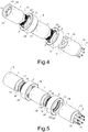
- the extrusion die comprises at least two modules 1, in particular three modules 1, which can be joined together to form at least one channel for the material to be extruded.
- the modules 1 are arranged in series and joined together one after the other.
- the die can be arranged between a press and a profiling head, both not shown in the figures, in particular for the extrusion of PTFE paste.
- the modules 1 comprise a channel 11 having a substantially tubular shape which extends along a longitudinal axis L, preferably with a section having a profile which varies gradually along the longitudinal axis L, i.e. without steps in the channel 11, so as to facilitate the flow of the material to be extruded during the extrusion operation.
- the ends of the channel 11 of a module 1 comprise respectively an inlet mouth 11a and an outlet mouth 11b in which the material to be extruded can respectively enter and exit.
- the inlet mouth 11a and/or the outlet mouth 11b have a substantially elliptical profile, in particular circular, and have a substantially constant section along an initial and/or final section of the channel 11.
- the area of the section of the inlet mouth 11a can be the same of (as in the second module 1 shown in the figures) or greater than (as in the first and third module 1 shown in the figures) the area of the section of the outlet mouth 11b.
- the profile of the outlet mouth 1 1b of the first or second module 1 is substantially the same as the profile of the inlet mouth 11a of the second or third module 1, respectively, so that the final section of the channel 11 of a module 1 can be aligned with the initial section of channel 11 of the adjacent module 1, if present.
- the channel 11 further comprises, between the inlet mouth 1 1a and the outlet mouth 11b, in sequence, a compression portion 11c, a central portion 11d and an expansion portion 11e connected to each other.
- the inlet mouth 11a, the outlet mouth 11b, the compression portion 11c, the central portion 11d and/or the expansion portion 11e are substantially coaxial, in particular substantially aligned with the longitudinal axis L of the module 1.
- the area of the section of the central portion 11d is preferably smaller than the area of the inlet mouth 11a and of the area of the outlet mouth 11b, so that the channel 11, on the whole, has a substantially hourglass shape which develops along the longitudinal axis L, i.e. a shape comprising a constriction at the central portion 11d.
- the succession of several modules 1 joined together allows the succession of several channels 11 aligned with each other, so that the material to be extruded is subjected to a series of compressions and expansions in the modules 1.
- the central portion 11d of the channel 11 has a substantially constant section along a central section of the channel 11 and/or a substantially bilobed profile, as in the first and third module 1, or substantially elliptical, in particular circular, as in the second module 1.
- the compression portion 11c of the channel 11 connects the profile of the inlet mouth 11a of the channel 11 to the profile of the central section 11d of the channel 11, so as to compress the material to be extruded.
- the expansion section 11e of the channel 11 connects the profile of the central section 11d of the channel 11 to the outlet mouth 11b of the channel 11, so as to expand the material to be extruded.
- two modules 1, in particular the first module 1 and the third module 1 are arranged so that the major axes MA of the bilobed profile of the central section 11d of their channels 11 are substantially perpendicular to each other.
- each module 1 has a substantially cylindrical shape and/or comprises at least one rib 12, for example of a substantially cylindrical shape, which projects outwardly in the direction of the longitudinal axis L and is adapted to be coupled with another module 1 or with another device, such as an extruder press.
- Each module 1 may comprise at least one seat 13, in particular a substantially cylindrical groove, adapted to be coupled with the rib 12 of another module 1 or with another device, for example the head of an extruder.
- the two bases of the module 1 may respectively comprise an inlet face 14, surrounded by the rib 12 and/or comprising the inlet mouth 11a, and an outlet face 15, surrounded by the seat 13 and/or comprising the outlet mouth 11b.
- the inlet face 14 and/or the outlet face 15 have a substantially elliptical shape, in particular circular.
- Each module 1 may further comprise first axial holes 16 and/or second axial holes 17.
- the first axial holes 16 are through holes, i.e. they lead to the inlet face 14 and to the outlet face 15, while the second axial holes 17 they are threaded and blind, i.e. they lead only to one of the two faces, in particular to the outlet face 15.
- the first axial holes 16 and/or the second axial holes 17 are substantially parallel to each other and/or to the longitudinal axis L and are arranged substantially at the same distance from the longitudinal axis L, forming angles of 360°/h1 and/or 360°/h2 between them, where h1 is the number of the first axial holes 16 and h2 is the number of the second axial holes 17.
- the third module 1 may not comprise second axial holes 17.
- the modules 1 are aligned and oriented to each other so that the first axial holes 16 of a module 1 are aligned with the second axial holes 17 of at least one adjacent module 1. Screws 4 can then be inserted in the first axial holes 16 from the outlet face 15 of a module 1, pass through the inlet face 14 of the same module 1 and screwed into the second axial holes 17 of the adjacent module 1 to join these two modules 1 together.
- the first axial holes 16 comprise a neck 16a acting as a stop for the head of the screws 4.
- At least one filter 3 is preferably arranged between two adjacent modules 1 or between a module 1 and another device connected to it.
- the filter 3 is arranged between the outlet face 15 of a module 1, for example the first or second module 1, and the inlet face 14 of an adjacent module 1, for example the second or third module 1.
- the seat 13 of a module 1 is preferably higher than the rib 12 of the adjacent module 1 or even of the same module 1, so that the filter 3 is pressed by the screws 4 against the inlet face 14 and the outlet face 15 of two adjacent modules 1, in particular also surrounded by the rib 12.
- At least one channel 11 of a module 1 is connected with the outside of the modules 1 through at least one filter 3, so that fluids can be sucked from the channel 11 or introduced into the channel 11 through the filter 3.
- At least one module 1 may comprise one or more ducts 18 to connect the filter 3 with at least one external surface of the module 1.
- the ducts 18 are substantially perpendicular to the longitudinal axis L, in particular arranged around the filter 3, so as to pass through the rib 12, if present.
- the ducts 1 can be uniformly distributed around the modules 1 and are in particular eight, so as to form angles between them of about 360°/8, i.e. about 45°.
- the modules 1 are preferably made in a single piece of metallic material in which the channel 11, the first axial holes 16, the second axial holes 17 and/or the ducts 18 are obtained by removing material, for example by means of CNC drill and/or milling machine.
- a manifold 2 is preferably arranged outside at least one module 1 for connecting the filter 3, in particular through the ducts 18, to fluid suction/compression means, in particular to a vacuum pump (not shown in the figures).
- the manifold 2 has an annular shape, in which the inner surface has a substantially cylindrical shape and/or comprises at least one groove 23 adapted to be arranged around the filter 3, in particular the ducts 18, and connected to at least one fitting 24 preferably provided of a threaded hole for said fluid suction/compression means.
- the groove 23 is preferably arranged between two further grooves in which a gasket 25 is arranged which ensures the sealing of fluids between the manifold 2 and the module 1.
- the manifold 2 also comprises fixing means for removably fixing the manifold 2 to the module 1, in particular a threaded through hole 21, not coinciding with the groove 23, into which a screw 22 is screwed, whose stem can press on the outer wall of the module 1 during its screwing.
- the filter 3 preferably comprises a plate which may have a substantially elliptical, in particular circular shape.
- the filter 3 may comprise a central opening 31 for the passage of the material to be extruded between the channels 11 of two adjacent modules 1 and/or a plurality of through holes 32 for the passage of the screws 4 which join these two modules 1 together.
- the filter therefore comprises an inner edge 33, an outer edge 34, an inlet face 35 and an outlet face 36.
- the faces 35 and/or 36 of the filter 3 are substantially the same and/or comprise radial grooves 37 which connect the inner edge 33 to the outer edge 34.
- the faces 35 and/or 36 of the filter 3 may comprise one or more annular grooves 38, preferably concentric, which connect two or more radial grooves 37 between them, so that the radial grooves 37 and the annular grooves 38 of the faces 35 and/or 36 form a network of grooves.
- a passage of fluids occurs between the channels 11 and the ducts 18 of the modules 1 through the radial grooves 37 or also the annular grooves 38, delimited by the inlet face 14 of a module 1 and by the outlet face 15 of the adjacent module 1.
- the radial grooves 37 and/or the annular grooves 38 have a depth d equal to 10-30% of the thickness t of the filter 3, equal to 0,5-1,5 mm, in particular about 1 mm, and/or a substantially constant and triangular section, in particular a section substantially in the form of an isosceles triangle having an angle at the vertex of 80°-100°, in particular about 90°, facing the filter 3.
- the radials grooves 37 are preferably equidistant and/or placed at intervals of 3-5°, in particular about 4°.
- the annular grooves 38 are for example from 3 to 5, in particular 4, and/or arranged at distances of 10-20 mm from one another.
- the filter 3 has a diameter of 80-120 mm, in particular about 100 mm, and the central opening 31 has a diameter of 40-50 mm, in particular about 45 mm.
Landscapes
- Engineering & Computer Science (AREA)
- Mechanical Engineering (AREA)
- Extrusion Moulding Of Plastics Or The Like (AREA)
Applications Claiming Priority (1)
| Application Number | Priority Date | Filing Date | Title |
|---|---|---|---|
| IT201800010977 | 2018-12-11 |
Publications (1)
| Publication Number | Publication Date |
|---|---|
| EP3666495A1 true EP3666495A1 (fr) | 2020-06-17 |
Family
ID=65861559
Family Applications (1)
| Application Number | Title | Priority Date | Filing Date |
|---|---|---|---|
| EP19213653.9A Withdrawn EP3666495A1 (fr) | 2018-12-11 | 2019-12-04 | Filière d'extrusion |
Country Status (1)
| Country | Link |
|---|---|
| EP (1) | EP3666495A1 (fr) |
Cited By (1)
| Publication number | Priority date | Publication date | Assignee | Title |
|---|---|---|---|---|
| CN111958940A (zh) * | 2020-08-25 | 2020-11-20 | 浙江华业塑料机械有限公司 | 一种能防止溢料的排气式机筒 |
Citations (1)
| Publication number | Priority date | Publication date | Assignee | Title |
|---|---|---|---|---|
| US2262989A (en) | 1938-03-26 | 1941-11-18 | Eastman Kodak Co | Method for forming thermoplastic sheeting |
-
2019
- 2019-12-04 EP EP19213653.9A patent/EP3666495A1/fr not_active Withdrawn
Patent Citations (1)
| Publication number | Priority date | Publication date | Assignee | Title |
|---|---|---|---|---|
| US2262989A (en) | 1938-03-26 | 1941-11-18 | Eastman Kodak Co | Method for forming thermoplastic sheeting |
Cited By (1)
| Publication number | Priority date | Publication date | Assignee | Title |
|---|---|---|---|---|
| CN111958940A (zh) * | 2020-08-25 | 2020-11-20 | 浙江华业塑料机械有限公司 | 一种能防止溢料的排气式机筒 |
Similar Documents
| Publication | Publication Date | Title |
|---|---|---|
| CN104180115B (zh) | 流体分流装置 | |
| EP3146210B1 (fr) | Pompe alternative présentant une meilleure géométrie d'alésage transversal de cylindre de fluide | |
| CN109915671A (zh) | 具有改进的排出性的管道端部配件 | |
| CN108368955A (zh) | 管连接器 | |
| WO2017042874A1 (fr) | Procédé de raccordement de conduite sous pression et procédé de construction de conduite sous pression à bride | |
| KR102285268B1 (ko) | 공기 흡입 취출 공구 | |
| CN206553199U (zh) | 一种新型固态二氧化碳制造机的挤压型腔 | |
| CN207787309U (zh) | 分流板及铝合金管材挤压模 | |
| CN214427123U (zh) | 一种薄壁圆管件水压试验装置 | |
| CN111113296B (zh) | 一种环形曲面流量标定工装 | |
| CN221568832U (zh) | 泵体组件、转缸泵和换热设备 | |
| CN217930595U (zh) | 可用于传感器插入式耐正负高压高温旋转接头 | |
| CN108947213B (zh) | 小口压-吹法冷却器模具 | |
| CN117514788A (zh) | 泵体组件、转缸泵和换热设备 | |
| CN113389781B (zh) | 一种管梁联接接头 | |
| CN113664279B (zh) | 沿横截面切断圆形钢管时零尾料的假尾装置及其使用方法 | |
| EP3267136A1 (fr) | Élément cylindrique de refroidissement et de chauffage | |
| DE202017102366U1 (de) | Fluidarmatur für eine Fluidleitung | |
| CN110234917B (zh) | 连接至少两个流体阀的方法和用于实现的流体连通的系统 | |
| CN220294457U (zh) | 用于混合器的管路连接件以及混合器 | |
| CN223768330U (zh) | 一种穿板内流接头 | |
| CN211386346U (zh) | 用于硬铝挤压的分体式上模及模具 | |
| US9889592B2 (en) | Extrusion die with curved face | |
| CN119075801A (zh) | 管路连接件及其安装方法、混合器 | |
| CN214919608U (zh) | 一种组合式胀形模具 |
Legal Events
| Date | Code | Title | Description |
|---|---|---|---|
| PUAI | Public reference made under article 153(3) epc to a published international application that has entered the european phase |
Free format text: ORIGINAL CODE: 0009012 |
|
| STAA | Information on the status of an ep patent application or granted ep patent |
Free format text: STATUS: THE APPLICATION HAS BEEN PUBLISHED |
|
| AK | Designated contracting states |
Kind code of ref document: A1 Designated state(s): AL AT BE BG CH CY CZ DE DK EE ES FI FR GB GR HR HU IE IS IT LI LT LU LV MC MK MT NL NO PL PT RO RS SE SI SK SM TR |
|
| AX | Request for extension of the european patent |
Extension state: BA ME |
|
| STAA | Information on the status of an ep patent application or granted ep patent |
Free format text: STATUS: THE APPLICATION IS DEEMED TO BE WITHDRAWN |
|
| 18D | Application deemed to be withdrawn |
Effective date: 20201218 |