EP3666533A1 - Élément de fixation et appareil de formation d'images - Google Patents
Élément de fixation et appareil de formation d'images Download PDFInfo
- Publication number
- EP3666533A1 EP3666533A1 EP19212441.0A EP19212441A EP3666533A1 EP 3666533 A1 EP3666533 A1 EP 3666533A1 EP 19212441 A EP19212441 A EP 19212441A EP 3666533 A1 EP3666533 A1 EP 3666533A1
- Authority
- EP
- European Patent Office
- Prior art keywords
- spacer
- length
- threaded portion
- support plate
- protruding
- Prior art date
- Legal status (The legal status is an assumption and is not a legal conclusion. Google has not performed a legal analysis and makes no representation as to the accuracy of the status listed.)
- Granted
Links
Images





Classifications
-
- G—PHYSICS
- G03—PHOTOGRAPHY; CINEMATOGRAPHY; ANALOGOUS TECHNIQUES USING WAVES OTHER THAN OPTICAL WAVES; ELECTROGRAPHY; HOLOGRAPHY
- G03G—ELECTROGRAPHY; ELECTROPHOTOGRAPHY; MAGNETOGRAPHY
- G03G21/00—Arrangements not provided for by groups G03G13/00 - G03G19/00, e.g. cleaning, elimination of residual charge
- G03G21/16—Mechanical means for facilitating the maintenance of the apparatus, e.g. modular arrangements
- G03G21/1642—Mechanical means for facilitating the maintenance of the apparatus, e.g. modular arrangements for connecting the different parts of the apparatus
- G03G21/1647—Mechanical connection means
-
- F—MECHANICAL ENGINEERING; LIGHTING; HEATING; WEAPONS; BLASTING
- F16—ENGINEERING ELEMENTS AND UNITS; GENERAL MEASURES FOR PRODUCING AND MAINTAINING EFFECTIVE FUNCTIONING OF MACHINES OR INSTALLATIONS; THERMAL INSULATION IN GENERAL
- F16B—DEVICES FOR FASTENING OR SECURING CONSTRUCTIONAL ELEMENTS OR MACHINE PARTS TOGETHER, e.g. NAILS, BOLTS, CIRCLIPS, CLAMPS, CLIPS OR WEDGES; JOINTS OR JOINTING
- F16B35/00—Screw-bolts; Stay-bolts; Screw-threaded studs; Screws; Set screws
- F16B35/04—Screw-bolts; Stay-bolts; Screw-threaded studs; Screws; Set screws with specially-shaped head or shaft in order to fix the bolt on or in an object
- F16B35/041—Specially-shaped shafts
-
- B—PERFORMING OPERATIONS; TRANSPORTING
- B41—PRINTING; LINING MACHINES; TYPEWRITERS; STAMPS
- B41J—TYPEWRITERS; SELECTIVE PRINTING MECHANISMS, i.e. MECHANISMS PRINTING OTHERWISE THAN FROM A FORME; CORRECTION OF TYPOGRAPHICAL ERRORS
- B41J11/00—Devices or arrangements of selective printing mechanisms, e.g. ink-jet printers or thermal printers, for supporting or handling copy material in sheet or web form
- B41J11/007—Conveyor belts or like feeding devices
-
- F—MECHANICAL ENGINEERING; LIGHTING; HEATING; WEAPONS; BLASTING
- F16—ENGINEERING ELEMENTS AND UNITS; GENERAL MEASURES FOR PRODUCING AND MAINTAINING EFFECTIVE FUNCTIONING OF MACHINES OR INSTALLATIONS; THERMAL INSULATION IN GENERAL
- F16B—DEVICES FOR FASTENING OR SECURING CONSTRUCTIONAL ELEMENTS OR MACHINE PARTS TOGETHER, e.g. NAILS, BOLTS, CIRCLIPS, CLAMPS, CLIPS OR WEDGES; JOINTS OR JOINTING
- F16B33/00—Features common to bolt and nut
- F16B33/02—Shape of thread; Special thread-forms
-
- F—MECHANICAL ENGINEERING; LIGHTING; HEATING; WEAPONS; BLASTING
- F16—ENGINEERING ELEMENTS AND UNITS; GENERAL MEASURES FOR PRODUCING AND MAINTAINING EFFECTIVE FUNCTIONING OF MACHINES OR INSTALLATIONS; THERMAL INSULATION IN GENERAL
- F16B—DEVICES FOR FASTENING OR SECURING CONSTRUCTIONAL ELEMENTS OR MACHINE PARTS TOGETHER, e.g. NAILS, BOLTS, CIRCLIPS, CLAMPS, CLIPS OR WEDGES; JOINTS OR JOINTING
- F16B37/00—Nuts or like thread-engaging members
- F16B37/04—Devices for fastening nuts to surfaces, e.g. sheets, plates
- F16B37/041—Releasable devices
- F16B37/042—Releasable devices locking by rotation
-
- G—PHYSICS
- G03—PHOTOGRAPHY; CINEMATOGRAPHY; ANALOGOUS TECHNIQUES USING WAVES OTHER THAN OPTICAL WAVES; ELECTROGRAPHY; HOLOGRAPHY
- G03G—ELECTROGRAPHY; ELECTROPHOTOGRAPHY; MAGNETOGRAPHY
- G03G15/00—Apparatus for electrographic processes using a charge pattern
- G03G15/65—Apparatus which relate to the handling of copy material
- G03G15/6502—Supplying of sheet copy material; Cassettes therefor
-
- G—PHYSICS
- G03—PHOTOGRAPHY; CINEMATOGRAPHY; ANALOGOUS TECHNIQUES USING WAVES OTHER THAN OPTICAL WAVES; ELECTROGRAPHY; HOLOGRAPHY
- G03G—ELECTROGRAPHY; ELECTROPHOTOGRAPHY; MAGNETOGRAPHY
- G03G21/00—Arrangements not provided for by groups G03G13/00 - G03G19/00, e.g. cleaning, elimination of residual charge
- G03G21/16—Mechanical means for facilitating the maintenance of the apparatus, e.g. modular arrangements
-
- G—PHYSICS
- G03—PHOTOGRAPHY; CINEMATOGRAPHY; ANALOGOUS TECHNIQUES USING WAVES OTHER THAN OPTICAL WAVES; ELECTROGRAPHY; HOLOGRAPHY
- G03G—ELECTROGRAPHY; ELECTROPHOTOGRAPHY; MAGNETOGRAPHY
- G03G21/00—Arrangements not provided for by groups G03G13/00 - G03G19/00, e.g. cleaning, elimination of residual charge
- G03G21/16—Mechanical means for facilitating the maintenance of the apparatus, e.g. modular arrangements
- G03G21/1661—Mechanical means for facilitating the maintenance of the apparatus, e.g. modular arrangements means for handling parts of the apparatus in the apparatus
- G03G21/1685—Mechanical means for facilitating the maintenance of the apparatus, e.g. modular arrangements means for handling parts of the apparatus in the apparatus for the fixing unit
Definitions
- the present disclosure relates to a fixing member and an image forming apparatus.
- An image forming apparatus includes a conveyance unit, a swinging body, and a fixing member.
- the fixing member is a bolt.
- the fixing member attaches the conveyance unit to the swinging body in a swingable manner.
- the bolt is fastened to render the conveyance unit immovable relative to the swinging body.
- a fixing member in an aspect of the present disclosure includes a bolt member and a spacer annular in shape.
- the bolt member includes a base portion, a protruding portion protruding from the base portion, and a threaded portion at a tip of the protruding portion.
- the spacer is attached to the protruding portion in a slidable manner between the base portion and the threaded portion.
- a first member is sandwiched between the base portion and the spacer.
- a second member different from the first member is sandwiched between a nut member screwed on the threaded portion and the spacer.
- An image forming apparatus includes a conveyance unit, a lifting and lowering unit, a fixing member, and a nut member.
- the conveyance unit includes a bottom plate and conveys a sheet.
- the lifting and lowering unit includes an elastic body and a support plate, and lifts and lowers the conveyance unit.
- the support plate supports the conveyance unit with the elastic body interposed therebetween.
- the fixing member fixes the conveyance unit to the lifting and lowering unit.
- the nut member is attached to the fixing member.
- the fixing member includes a bolt member and a spacer annular in shape.
- the bolt member includes a base portion, a protruding portion protruding from the base portion, and a threaded portion located at a tip of the protruding portion.
- the spacer is attached to the protruding portion in a slidable manner between the base portion and the threaded portion.
- the bottom plate is sandwiched between the base portion and the spacer.
- the support plate is sandwiched between the spacer and a nut member threadedly engaged with the threaded portion.
- the length of the elastic body is maintained at a predetermined length due to the spacer between the bottom plate and the support plate.
- the following describes an inkjet recording apparatus 1 according to an embodiment of the present disclosure with reference to drawings.
- the inkjet recording apparatus 1 is an example of an image forming apparatus. Note that elements that are the same or equivalent are indicated by the same reference signs in the drawings and description thereof are not repeated.
- the drawings mainly illustrate respective elements in a schematic manner for easy understanding.
- FIG. 1 is a diagram illustrating the inkjet recording apparatus 1 according to the present embodiment.
- An X axis, a Y axis, and a Z axis in the drawings are perpendicular to each other.
- the X axis and the Y axis each extend in a direction parallel to a horizontal direction, and the Z axis extends in a direction parallel to a vertical direction.
- a Y-axis direction is opposite to a conveyance direction D.
- the inkjet recording apparatus 1 includes a housing 2, a sheet feed section 3, a recording head section 4, a conveyance section 5, a cap unit 6, a wiper unit 7, an ejection section 8, a controller 9, and a moving mechanism 10.
- the housing 2 accommodates the sheet feed section 3, the recording head section 4, the conveyance section 5, the cap unit 6, the wiper unit 7, the ejection section 8, the controller 9, and the moving mechanism 10.
- FIG. 2 is a perspective view illustrating the fixing member 200.
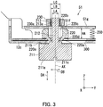
- FIG. 3 is a cross-sectional view illustrating the fixing member 200.
- the inkjet recording apparatus 1 further includes the fixing member 200 and a nut member 230.
- the inkjet recording apparatus 1 includes a plurality of fixing members 200 and a plurality of nut members 230. Each of the nut members 230 is attachable to a corresponding one of the fixing members 200.
- the fixing members 200 are used in transportation of the inkjet recording apparatus 1.
- the sheet feed section 3 includes sheet feed cassettes 31, sheet feed rollers 32a, a sheet feed roller 32b, and a manual feed tray 33.
- the sheet feed cassettes 31 are disposed in a lower part of the housing 2.
- the sheet feed cassettes 31 are detachably attached to the housing 2.
- a plurality of sheets S can be stored in a stacked state.
- a portion of the manual feed tray 33 is exposed from the housing 2 to the outside.
- a plurality of sheets S can be loaded in a stacked state.
- Each sheet S is, for example, plain paper, copy paper, recycled paper, thin paper, thick paper, glossy paper, or an overhead projector (OHP) sheet.
- OHP overhead projector
- the sheet feed rollers 32a and the sheet feed roller 32b are pickup rollers. Each sheet feed roller 32a picks up the sheets S stored in the sheet feed cassette 31 one by one from the top. The sheet feed roller 32b picks up the sheets S loaded on the manual feed tray 33 one by one from the top. The sheet feed rollers 32a and the sheet feed roller 32b each feeds the picked sheet S to the conveyance section 5.
- the conveyance section 5 conveys the sheet S along a conveyance path of the sheet S.
- the conveyance path of the sheet S extends from the sheet feed section 3 to the ejection section 8 via the recording head section 4.
- the conveyance section 5 includes a conveyance unit 51 and a plurality of roller pairs disposed along the conveyance path.
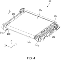
- FIG. 4 is a perspective view illustrating the conveyance unit 51.
- the conveyance unit 51 conveys the sheet S in the conveyance direction D.
- the conveyance unit 51 includes a conveyor belt 51a, a driving roller 51b, a driven roller 51c, paired wall sections 51e, and paired bottom plates 51g.
- a driving roller 51b and a driven roller 51c are disposed between the paired wall sections 51e.
- the bottom plates 51g are each a plate parallel to a horizontal plane.
- the bottom plates 51g form the respective bottoms of the paired wall sections 51e.
- the conveyor belt 51a is an endless belt.
- the conveyor belt 51a is stretched around the driving roller 51b and the driven roller 51c.
- the conveyance unit 51 conveys to the ejection section 8 the sheet S with it loaded on a loading surface.
- the loading surface means a part of an outer circumferential surface of the conveyor belt 51a on which the sheet S is to be loaded.
- each of the bottom plates 51g of the conveyance unit 51 includes a third hole 51f.
- the bottom plate 51g includes a plurality of third holes 51f.
- Each of the third holes 51f penetrates the bottom plate 51g in an axial direction DA.
- the axial direction DA is, for example, substantially parallel to the vertical direction.
- the nut member 230 is fixed to the bottom plate 51g. Specifically, the nut member 230 is fixed to the upper surface of the bottom plate 51g so as to overlap with the third hole 51f in the axial direction DA. That is, the nut member 230 is integral with the inkjet recording apparatus 1. Therefore, according to the embodiment, attachment of the fixing member 200 at a predetermined position can be achieved only by preparation of the fixing member 200.
- the nut member 230 is an annular body.
- the nut member 230 is made from, for example, metal.
- the inner circumferential surface of the nut member 230 has a second female thread 230a.
- the second female thread 230a has an inner diameter of a second length LB and a root diameter of a third length LC.
- the second length LB is smaller than the third length LC.
- the recording head section 4 faces the loading surface of the conveyance unit 51.
- the recording head section 4 forms an image with ink on the sheet S being conveyed by the conveyance unit 51. Subsequently, the sheet S with the image formed thereon is sent to the ejection section 8.
- the recording head section 4 includes a head housing 4a and recording heads 4y, 4m, 4c, and 4k.
- the recording heads 4y, 4m, 4c, 4k are held by the head housing 4a.
- the recording head 4y ejects a yellow ink.
- the recording head 4m ejects a magenta ink.
- the recording head 4c ejects a cyan ink.
- the recording head 4k ejects a black ink.
- the ejection section 8 includes an exit tray 81. A portion of the exit tray 81 is exposed from the housing 2 to the outside. The sheet S with the image formed thereon is ejected onto the exit tray 81. Sheets S with an image formed thereon are stacked one by one on the exit tray 81.
- the wiper unit 7 includes wiper blades 7y, 7m, 7c, and 7k.
- the wiper blades 7y, 7m, 7c, and 7k wipe off inks from the recording head section 4.
- the wiper blade 7y corresponds to the recording head 4y.
- the wiper blade 7m corresponds to the recording head 4m.
- the wiper blade 7c corresponds to the recording head 4c.
- the wiper blade 7k corresponds to the recording head 4k.
- the cap unit 6 includes caps 6y, 6m, 6c, and 6k.
- the cap 6y corresponds to the recording head 4y.
- the cap 6m corresponds to the recording head 4m.
- the cap 6c corresponds to the recording head 4c.
- the cap 6k corresponds to the recording head 4k.
- the cap unit 6 brings the caps 6y, 6m, 6c, and 6k into close contact with the recording heads 4y, 4m, 4c, and 4k, respectively, when the recording head section 4 is not used for a specific time period or longer. As a result, drying of the inks of the recording heads 4y, 4m, 4c, and 4k is prevented.
- the controller 9 controls operation of the inkjet recording apparatus 1.
- the controller 9 includes a processor such as a central processing unit (CPU), and storage such as a hard disk drive and memory.
- the storage stores therein various computer programs to be executed by the processor.
- the processor executes the various computer programs stored in the storage to control the sheet feed section 3, the recording head section 4, the conveyance section 5, the cap unit 6, the wiper unit 7, and the moving mechanism 10.
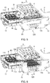
- FIGS. 5 and 6 are perspective views illustrating the conveyance unit 51, the cap unit 6, and the wiper unit 7.
- the conveyance unit 51 is located at an upper limit position P1 and the cap unit 6 is located at a retraction position P3.
- the wiper unit 7 illustrated in FIG. 1 is located at a retraction position P5 although the wiper unit 7 is hidden behind the cap unit 6 in FIG. 5 .
- the conveyance unit 51 is located at a lower limit position P2 and the cap unit 6 is located at the retraction position P3.
- the wiper unit 7 illustrated in FIG. 1 is located at a retraction position P5 although the wiper unit 7 is hidden behind the cap unit 6 in FIG. 5 .
- the upper limit position P1 is a position at which the conveyance unit 51 is close to the recording head section 4.
- the lower limit position P2 is a position which is vertically below the upper limit position P1 and at which the conveyance unit 51 is away from the recording head section 4.
- the retraction position P3 is a position to which the cap unit 6 is moved in the conveyance direction D relative to the recording head section 4.
- the retraction position P5 is a position which is vertically below the retraction position P3 and to which the wiper unit 7 is moved in the conveyance direction D relative to the recording head section 4.
- the moving mechanism 10 moves the conveyance unit 51, the cap unit 6, and the wiper unit 7 within the housing 2.
- the moving mechanism 10 includes a first casing 11, a first casing moving mechanism 15, and a lifting and lowering unit 320.
- the lifting and lowering unit 320 includes a second casing 12 and a conveyance unit moving mechanism (not illustrated).
- the second casing 12 is fixed to the housing 2.
- the second casing 12 includes a wall section 12a and a wall section 12b, and a support plate 12c parallel to the horizontal plane.
- the wall 12a and the wall 12b face each other in the X-axis direction.
- the conveyance unit 51 is placed on the support plate 12c.
- the conveyance unit moving mechanism moves, using a wire 100 and a drum 110, the conveyance unit 51 placed on the support plate 12c up and down between the upper limit position P1 and the lower limit position P2 in the second casing 12.
- the loading surface of the conveyance unit 51 at the upper limit position P1 faces the recording head section 4 in the vertical direction.
- the loading surface of the conveyance unit 51 is close to the lower end of the recording head section 4 at a clearance sufficient for conveyance of the sheet S (for example, 3 mm).
- the clearance between the loading surface of the conveyance unit 51 and the lower end of the recording head section 4 is, for example, 200 mm.
- FIG. 8 is an enlarged perspective view illustrating a support plate 12c in the embodiment.
- the support plate 12c includes a plurality of (for example, four) elastic bodies 250 and a plurality of (for example, four) through holes 300.
- the elastic bodies 250 are disposed on the upper surface of the support plate 12c.
- the four elastic bodies 250 are disposed at a corresponding one of the four corners of the upper surface of the support plate 12c.
- the conveyance unit 51 is placed on the support plate 12c with the elastic bodies 250 therebetween.
- the through hole 300 has a first hole portion 310 and a second hole portion 311.
- the first hole portion 310 and the second hole portion 311 penetrate the support plate 12c in the axial direction DA.
- the first hole portion 310 and the second hole portion 311 communicate with each other in a direction DB that intersects the axial direction DA.
- the first hole portion 310 and the second hole portion 311 communicate with each other in the direction DB that is perpendicular to the axial direction DA in the present embodiment.
- the second hole portion 311 is smaller than the first hole portion 310.
- the through hole 300 is located in a vicinity of each elastic body 250.
- the first casing 11 includes a wall section 11a and a wall section 11b.
- the wall section 11a and the wall section 11b face each other in the X-axis direction.
- the cap unit 6 and the wiper unit 7 are attached to the inside of the first casing 11.
- the first casing moving mechanism 15 moves the cap unit 6 between the retraction position P3 and a standby position P4 ( FIG. 1 ).
- the cap unit 6 at the standby position P4 faces the recording head section 4 in the vertical direction.
- the first casing moving mechanism 15 moves the wiper unit 7 between the retraction position (indicated by solid lines in FIG. 1 ) and the standby position.
- the wiper unit 7 at the standby position faces the recording head section 4 in the vertical direction.
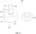
- FIG. 9 is an exploded perspective view illustrating the fixing member 200.
- the fixing member 200 includes the bolt member 210 and the spacer 220 annular in shape.
- the bolt member 210 includes a base portion 211, a protruding portion 212, and a threaded portion 213.
- the bolt member 210 is made from, for example, metal.
- the base portion 211 includes a base end surface 211a, a front end surface 211b, and an engaging part 211c.
- the base end surface 211a and the front end surface 211b each intersect the axial direction DA.
- the base end surface 211a and the front end surface 211b are each perpendicular to the axial direction DA.
- the axial direction DA is a direction along an axis AX of the bolt member 210 passing through the threaded portion 213 and the base portion 211.
- the base end surface 211a is located at a position more distant from the threaded portion 213 than the front end surface 211b.
- the engaging part 211c is located in the base end surface 211a. The engaging part 211c engages with a tool.
- the engaging part 211c is located in the base end surface 211a, a user can use the tool from a side of the base end surface 211a.
- the fixing member 200 can be easily attached to the nut member 230 using the tool.
- the protruding portion 212 protrudes from the front end surface 211b of the base portion 211 in the axial direction DA.
- the protruding portion 212 has a diameter of the first length LA.
- the threaded portion 213 is located at a tip of the protruding portion 212.
- the outer peripheral surface of the threaded portion 213 includes a male thread 213a.
- the root diameter of the male thread 213a is the second length LB longer than or equal to the first length LA.
- the outer diameter of the male thread 213a is the third length LC longer than the second length LB.
- the spacer 220 annular in shape is made from, for example, metal.
- the spacer 220 is, for example, a ring, a square ring, or a hexagonal ring.
- the spacer 220 has a first abutment surface 220c and a second abutment surface 220d that are parallel to and face each other.
- the first abutment surface 220c forms an upper surface of a truncated cone.
- the central part of the second abutment surface 220d forms a protrusion 220e protruding in a truncated cone shape.
- a recess 220b is formed toward the second abutment surface 220d.
- a bottom surface of the recess 220b has a first female thread 220a penetrating toward the second abutment surface 220d side.
- the first female thread 220a has an inner diameter of the second length LB and a root diameter of the third length LC.
- a length HA in the thickness direction of the spacer 220 is a predetermined distance.
- the predetermined distance is a distance that is shorter than the natural length of the elastic body 250 and that inhibit plastic deformation of the elastic body 250.
- the natural length of the elastic body 250 is a length of the elastic body 250 free from any force applied thereto (not stretched or compressed).
- the recess 220b extends in a direction from the threaded portion 213 toward the base portion 211. That is, the recess 220b is formed in the first abutment surface 220c of the spacer 220, which is the surface facing the threaded portion 213.
- the recess 220b has a predetermined size. Specifically, the recess 220b has a size large enough to receive the threaded portion 213.
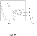
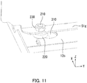
- FIGS. 10 and 11 are each a perspective view illustrating how to use the fixing member 200 in the embodiment.
- the user For transportation of the inkjet recording apparatus 1, the user prepares the bolt member 210 and the spacer 220 as illustrated in FIGS. 3 , 10 , and 11 .
- the user attaches the spacer 220 to the protruding portion 212 of the bolt member 210. Specifically, the user first screws the spacer 220 onto the threaded portion 213 of the bolt member 210. After passing through the threaded portion 213, the spacer 220 is attached around the protruding portion 212.
- the inner diameter of the spacer 220 is the second length LB, and the diameter of the protruding portion 212 is the first length LA. That is, the spacer 220 is slidable on the protruding portion 212.
- the inner diameter of the spacer 220 is the second length LB, and the diameter of the threaded portion 213 is the third length LC.
- the spacer 220 cannot be removed from the threaded portion 213 unless it is threadedly rotated. Therefore, in the embodiment, the spacer 220 can be attached to the protruding portion 212 in a slidable manner between the base portion 211 and the threaded portion 213.
- the user inserts the protruding portion 212 and the threaded portion 213 of the bolt member 210 with the spacer 220 from the lower side of the first hole portion 310 in the support plate 12c.
- the lower side means an opposite side of the support plate 12c to the bottom plate 51g.
- the size of the first hole portion 310 in the support plate 12c is such a size that the spacer 220 is allowed to pass therethrough but the base portion 211 is not.
- the size of the second hole portion 311 in the support plate 12c is such a size that neither the spacer 220 nor the base portion 211 is allowed to pass therethrough.
- the size of the second hole portion 311 is slightly larger than the outer diameter of the bottom surface of the protrusion 220e.
- the user moves the protruding portion 212 and the threaded portion 213 of the bolt member 210 with the spacer 220 in the direction DB from the first hole portion 310 to the second hole portion 311 in the support plate 12c.
- the protruding portion 212, the threaded portion 213, and the spacer 220 are moved from the first hole portion 310 to the second hole portion 311 in the through hole 300, the spacer 220 inserted upward from the support plate 12c is prevented from falling downward off the support plate 12c.
- the spacer 220 includes the protrusion 220e having a diameter smaller than that of the second hole portion 311 and protruding toward the second hole portion 311. Accordingly, the protrusion 220e is engaged with the second hole portion 311, and thus the spacer 220 is positioned so as not to move out of the second hole portion 311. Since the periphery of the first abutment surface 220c has a truncated cone shape, it is possible to prevent the periphery of the spacer 220 from interfering with the end of the bottom plate 51g.
- the user inserts the threaded portion 213 of the bolt member 210 through the third hole 51f in the support plate 12c and screws the threaded portion 213 into the nut member 230.
- the user engages a tool with the engaging part 211c to screw the threaded portion 213 into the nut member 230. Since the engaging part 211c is located on the base end surface 211a, the user can use the tool from the side of the base end surface 211a. Therefore, in a situation in which there is no work space on the bottom plate 51g due to the conveyor belt 51a being placed thereon, the fixing member 200 can be attached to the nut member 230 as long as there is work space below the support plate 12c.
- the support plate 12c is sandwiched between the base portion 211 and the spacer 220.
- the support plate 12c is an example of a first member.
- the bottom plate 51g is sandwiched between the spacer 220 and the nut member 230 threadedly engaged with the threaded portion.
- the bottom plate 51g is an example of a second member.
- the length of the elastic body 250 is kept at the predetermined length HA between the bottom plate 51g and the support plate 12c due to the presence of the spacer 220.
- the bottom plate 51g and the support plate 12c can be fixed with a space therebetween.
- the elastic bodies 250 are arranged between the bottom plate 51g and the support plate 12c, the length of the elastic body 250 is kept at the predetermined length HA between the bottom plate 51g and the support plate 12c due to the presence of the spacer 220. Accordingly, plastic deformation of the elastic body 250 present between the bottom plate 51g and the support plate 12c can be inhibited. Further, the conveyance unit 51 can be prevented from being damaged.
- the user engages the tool with the engaging part 211c to unscrew the threaded portion 213 of the bolt member 210 for detachment from the nut member 230. Since the engaging part 211c is located in the base end surface 211a, the user can use the tool from the side of the base end surface 211a. Therefore, in a situation in which there is no work space on the bottom plate 51g due to the conveyor belt 51a being placed thereon, the fixing member 200 can be detached as long as there is work space below the support plate 12c.
- the user pulls the base portion 211 downward to insert the threaded portion 213 of the bolt member 210 into the recess 220b of the spacer 220.
- the bolt member 210 previously located above the bottom plate 51g is retracted, and as a result, the bolt member 210 with the spacer 220 can be moved in the horizontal direction DB.
- the user moves the protruding portion 212 and the threaded portion 213 of the bolt member 210 with the spacer 220 in the direction DB from the second hole portion 311 to the first hole portion 310 in the support plate 11c.
- the protruding portion 212, the threaded portion 213, and the spacer 220 from the second hole portion 311 to the first hole portion 310 in the through hole 300 the spacer 220 that could not be pulled downward out of the support plate 12c can be pulled downward out of the support plate 12c.
- the fixing member 200 can be collected as long as there is work space below the support plate 12c.
Landscapes
- Engineering & Computer Science (AREA)
- General Engineering & Computer Science (AREA)
- Physics & Mathematics (AREA)
- General Physics & Mathematics (AREA)
- Mechanical Engineering (AREA)
- Ink Jet (AREA)
- Electrophotography Configuration And Component (AREA)
- Connection Of Plates (AREA)
- Accessory Devices And Overall Control Thereof (AREA)
Applications Claiming Priority (1)
| Application Number | Priority Date | Filing Date | Title |
|---|---|---|---|
| JP2018224795A JP7283060B2 (ja) | 2018-11-30 | 2018-11-30 | 固定部材及び画像形成装置 |
Publications (2)
| Publication Number | Publication Date |
|---|---|
| EP3666533A1 true EP3666533A1 (fr) | 2020-06-17 |
| EP3666533B1 EP3666533B1 (fr) | 2022-04-13 |
Family
ID=68732863
Family Applications (1)
| Application Number | Title | Priority Date | Filing Date |
|---|---|---|---|
| EP19212441.0A Active EP3666533B1 (fr) | 2018-11-30 | 2019-11-29 | Élément de fixation et appareil de formation d'images |
Country Status (4)
| Country | Link |
|---|---|
| US (1) | US10877429B2 (fr) |
| EP (1) | EP3666533B1 (fr) |
| JP (1) | JP7283060B2 (fr) |
| CN (1) | CN111255790B (fr) |
Citations (2)
| Publication number | Priority date | Publication date | Assignee | Title |
|---|---|---|---|---|
| US4022122A (en) * | 1973-08-16 | 1977-05-10 | Develop Kg/Dr. Eisbein And Co. | Pressing installation for a copying arrangement |
| JPH07168407A (ja) * | 1993-12-14 | 1995-07-04 | Ricoh Co Ltd | 画像形成装置 |
Family Cites Families (18)
| Publication number | Priority date | Publication date | Assignee | Title |
|---|---|---|---|---|
| JPS4710852Y1 (fr) * | 1968-08-27 | 1972-04-21 | ||
| JP2614042B2 (ja) * | 1987-03-26 | 1997-05-28 | マツダ株式会社 | 自動車のサスペンション装置 |
| JPH0359506U (fr) * | 1989-10-16 | 1991-06-12 | ||
| JPH056217U (ja) * | 1991-07-08 | 1993-01-29 | 株式会社東芝 | パネル取付け装置 |
| JPH0783213A (ja) * | 1993-09-13 | 1995-03-28 | Nissan Motor Co Ltd | 締結具 |
| JP2001048502A (ja) * | 1999-08-10 | 2001-02-20 | Nippon Alum Co Ltd | オゾン発生器の隙間設定機構 |
| EP1307658B1 (fr) * | 2000-08-10 | 2008-12-10 | Aoyama Seisakusho Co., Ltd. | Boulon, procede d'assemblage d'elements a l'aide de ce boulon, et procede de demontage |
| JP3758637B2 (ja) * | 2002-12-27 | 2006-03-22 | ブラザー工業株式会社 | 画像形成装置およびその組み付け方法 |
| JP2007079052A (ja) | 2005-09-13 | 2007-03-29 | Ricoh Co Ltd | 原稿搬送装置、原稿読取装置、画像形成装置 |
| JP2008141304A (ja) * | 2006-11-30 | 2008-06-19 | Konica Minolta Business Technologies Inc | 画像形成装置 |
| JP5201867B2 (ja) * | 2007-04-12 | 2013-06-05 | キヤノン株式会社 | 画像形成装置 |
| JP2010058431A (ja) * | 2008-09-05 | 2010-03-18 | Konica Minolta Ij Technologies Inc | インクジェット記録装置およびその調整方法 |
| JP2011155603A (ja) * | 2010-01-28 | 2011-08-11 | Kyocera Mita Corp | 画像形成装置,及び画像読取装置の装着方法 |
| US20130002758A1 (en) * | 2011-06-29 | 2013-01-03 | Alon Navon | Fastening Apparatus and Method Thereof |
| JP6365352B2 (ja) * | 2015-03-05 | 2018-08-01 | 京セラドキュメントソリューションズ株式会社 | 画像形成装置 |
| CN205615379U (zh) * | 2016-05-23 | 2016-10-05 | 烟台延锋江森座椅有限责任公司 | 盒式骨架座靠及用于连接的螺栓 |
| JP6532430B2 (ja) * | 2016-06-08 | 2019-06-19 | ハードロック工業株式会社 | 枢着装置、並びに、取付装置 |
| DE102016222181A1 (de) * | 2016-11-11 | 2018-05-17 | Siemens Aktiengesellschaft | Einrichtung zum Verbinden zweier Bauteile |
-
2018
- 2018-11-30 JP JP2018224795A patent/JP7283060B2/ja active Active
-
2019
- 2019-11-29 CN CN201911187545.7A patent/CN111255790B/zh active Active
- 2019-11-29 EP EP19212441.0A patent/EP3666533B1/fr active Active
- 2019-11-29 US US16/699,223 patent/US10877429B2/en active Active
Patent Citations (2)
| Publication number | Priority date | Publication date | Assignee | Title |
|---|---|---|---|---|
| US4022122A (en) * | 1973-08-16 | 1977-05-10 | Develop Kg/Dr. Eisbein And Co. | Pressing installation for a copying arrangement |
| JPH07168407A (ja) * | 1993-12-14 | 1995-07-04 | Ricoh Co Ltd | 画像形成装置 |
Also Published As
| Publication number | Publication date |
|---|---|
| CN111255790A (zh) | 2020-06-09 |
| US10877429B2 (en) | 2020-12-29 |
| JP7283060B2 (ja) | 2023-05-30 |
| JP2020085206A (ja) | 2020-06-04 |
| EP3666533B1 (fr) | 2022-04-13 |
| CN111255790B (zh) | 2021-11-23 |
| US20200174421A1 (en) | 2020-06-04 |
Similar Documents
| Publication | Publication Date | Title |
|---|---|---|
| JP6888482B2 (ja) | 記録ヘッド位置調整機構、及び、画像形成装置 | |
| US20180354739A1 (en) | Printing apparatus | |
| US11267269B2 (en) | Recording-head position adjustment mechanism, recording-head module, and image forming apparatus | |
| EP3345849A1 (fr) | Pince de rouleau automatique | |
| EP3666533B1 (fr) | Élément de fixation et appareil de formation d'images | |
| JP6565141B2 (ja) | 記録紙供給装置、ロール紙プリンター、ならびにニアエンド状態検出方法 | |
| JP7098420B2 (ja) | 記録装置および記録装置の制御方法 | |
| KR101150988B1 (ko) | 급지유닛 및 이를 구비하는 화상형성장치 | |
| EP1642737B1 (fr) | Renvoyeur dans un diispositif automatique d'alimentation et appareil d'enregistrement ou appareil à éjection de liquide équipé de celui-ci | |
| US20130001351A1 (en) | Printer | |
| EP3075689A1 (fr) | Imprimante à jet d'encre | |
| JP2013193219A (ja) | シート搬送装置および画像形成装置 | |
| CN110315853A (zh) | 喷墨打印设备 | |
| US12037213B2 (en) | Image recording apparatus | |
| JP2018089851A (ja) | インクジェット記録装置 | |
| CN214688210U (zh) | 一种压痕机的卡纸处理结构及压痕机 | |
| JP5375461B2 (ja) | 吊り上げ装置、搬送装置、画像形成装置 | |
| US9216584B2 (en) | Printer | |
| JP2020026080A (ja) | 記録装置および記録装置の制御方法 | |
| KR200496892Y1 (ko) | 간지 공급 장치의 대용량 표시 테이프 공급용 카트리지 | |
| EP2033872B1 (fr) | Appareil supportant un mécanisme, appareil d'alimentation de feuilles et appareil de formation d'images | |
| US7469114B2 (en) | Image forming apparatus and sheet feeding device in which weight exerted on lifting handles is equalized | |
| US8662660B2 (en) | Printer | |
| US10730322B2 (en) | Medium transport apparatus and printing apparatus | |
| US20230174337A1 (en) | Sheet feeding device and image forming apparatus |
Legal Events
| Date | Code | Title | Description |
|---|---|---|---|
| PUAI | Public reference made under article 153(3) epc to a published international application that has entered the european phase |
Free format text: ORIGINAL CODE: 0009012 |
|
| STAA | Information on the status of an ep patent application or granted ep patent |
Free format text: STATUS: THE APPLICATION HAS BEEN PUBLISHED |
|
| AK | Designated contracting states |
Kind code of ref document: A1 Designated state(s): AL AT BE BG CH CY CZ DE DK EE ES FI FR GB GR HR HU IE IS IT LI LT LU LV MC MK MT NL NO PL PT RO RS SE SI SK SM TR |
|
| AX | Request for extension of the european patent |
Extension state: BA ME |
|
| STAA | Information on the status of an ep patent application or granted ep patent |
Free format text: STATUS: REQUEST FOR EXAMINATION WAS MADE |
|
| 17P | Request for examination filed |
Effective date: 20201209 |
|
| RBV | Designated contracting states (corrected) |
Designated state(s): AL AT BE BG CH CY CZ DE DK EE ES FI FR GB GR HR HU IE IS IT LI LT LU LV MC MK MT NL NO PL PT RO RS SE SI SK SM TR |
|
| GRAP | Despatch of communication of intention to grant a patent |
Free format text: ORIGINAL CODE: EPIDOSNIGR1 |
|
| STAA | Information on the status of an ep patent application or granted ep patent |
Free format text: STATUS: GRANT OF PATENT IS INTENDED |
|
| RIC1 | Information provided on ipc code assigned before grant |
Ipc: G03G 21/16 20060101ALI20210930BHEP Ipc: G03G 15/00 20060101ALI20210930BHEP Ipc: B41J 11/00 20060101AFI20210930BHEP |
|
| INTG | Intention to grant announced |
Effective date: 20211102 |
|
| GRAS | Grant fee paid |
Free format text: ORIGINAL CODE: EPIDOSNIGR3 |
|
| GRAA | (expected) grant |
Free format text: ORIGINAL CODE: 0009210 |
|
| STAA | Information on the status of an ep patent application or granted ep patent |
Free format text: STATUS: THE PATENT HAS BEEN GRANTED |
|
| AK | Designated contracting states |
Kind code of ref document: B1 Designated state(s): AL AT BE BG CH CY CZ DE DK EE ES FI FR GB GR HR HU IE IS IT LI LT LU LV MC MK MT NL NO PL PT RO RS SE SI SK SM TR |
|
| REG | Reference to a national code |
Ref country code: GB Ref legal event code: FG4D |
|
| REG | Reference to a national code |
Ref country code: CH Ref legal event code: EP |
|
| REG | Reference to a national code |
Ref country code: DE Ref legal event code: R096 Ref document number: 602019013655 Country of ref document: DE |
|
| REG | Reference to a national code |
Ref country code: IE Ref legal event code: FG4D |
|
| REG | Reference to a national code |
Ref country code: AT Ref legal event code: REF Ref document number: 1483105 Country of ref document: AT Kind code of ref document: T Effective date: 20220515 |
|
| REG | Reference to a national code |
Ref country code: LT Ref legal event code: MG9D |
|
| REG | Reference to a national code |
Ref country code: NL Ref legal event code: MP Effective date: 20220413 |
|
| REG | Reference to a national code |
Ref country code: AT Ref legal event code: MK05 Ref document number: 1483105 Country of ref document: AT Kind code of ref document: T Effective date: 20220413 |
|
| PG25 | Lapsed in a contracting state [announced via postgrant information from national office to epo] |
Ref country code: NL Free format text: LAPSE BECAUSE OF FAILURE TO SUBMIT A TRANSLATION OF THE DESCRIPTION OR TO PAY THE FEE WITHIN THE PRESCRIBED TIME-LIMIT Effective date: 20220413 |
|
| PG25 | Lapsed in a contracting state [announced via postgrant information from national office to epo] |
Ref country code: SE Free format text: LAPSE BECAUSE OF FAILURE TO SUBMIT A TRANSLATION OF THE DESCRIPTION OR TO PAY THE FEE WITHIN THE PRESCRIBED TIME-LIMIT Effective date: 20220413 Ref country code: PT Free format text: LAPSE BECAUSE OF FAILURE TO SUBMIT A TRANSLATION OF THE DESCRIPTION OR TO PAY THE FEE WITHIN THE PRESCRIBED TIME-LIMIT Effective date: 20220816 Ref country code: NO Free format text: LAPSE BECAUSE OF FAILURE TO SUBMIT A TRANSLATION OF THE DESCRIPTION OR TO PAY THE FEE WITHIN THE PRESCRIBED TIME-LIMIT Effective date: 20220713 Ref country code: LT Free format text: LAPSE BECAUSE OF FAILURE TO SUBMIT A TRANSLATION OF THE DESCRIPTION OR TO PAY THE FEE WITHIN THE PRESCRIBED TIME-LIMIT Effective date: 20220413 Ref country code: HR Free format text: LAPSE BECAUSE OF FAILURE TO SUBMIT A TRANSLATION OF THE DESCRIPTION OR TO PAY THE FEE WITHIN THE PRESCRIBED TIME-LIMIT Effective date: 20220413 Ref country code: GR Free format text: LAPSE BECAUSE OF FAILURE TO SUBMIT A TRANSLATION OF THE DESCRIPTION OR TO PAY THE FEE WITHIN THE PRESCRIBED TIME-LIMIT Effective date: 20220714 Ref country code: FI Free format text: LAPSE BECAUSE OF FAILURE TO SUBMIT A TRANSLATION OF THE DESCRIPTION OR TO PAY THE FEE WITHIN THE PRESCRIBED TIME-LIMIT Effective date: 20220413 Ref country code: ES Free format text: LAPSE BECAUSE OF FAILURE TO SUBMIT A TRANSLATION OF THE DESCRIPTION OR TO PAY THE FEE WITHIN THE PRESCRIBED TIME-LIMIT Effective date: 20220413 Ref country code: BG Free format text: LAPSE BECAUSE OF FAILURE TO SUBMIT A TRANSLATION OF THE DESCRIPTION OR TO PAY THE FEE WITHIN THE PRESCRIBED TIME-LIMIT Effective date: 20220713 Ref country code: AT Free format text: LAPSE BECAUSE OF FAILURE TO SUBMIT A TRANSLATION OF THE DESCRIPTION OR TO PAY THE FEE WITHIN THE PRESCRIBED TIME-LIMIT Effective date: 20220413 |
|
| PG25 | Lapsed in a contracting state [announced via postgrant information from national office to epo] |
Ref country code: RS Free format text: LAPSE BECAUSE OF FAILURE TO SUBMIT A TRANSLATION OF THE DESCRIPTION OR TO PAY THE FEE WITHIN THE PRESCRIBED TIME-LIMIT Effective date: 20220413 Ref country code: PL Free format text: LAPSE BECAUSE OF FAILURE TO SUBMIT A TRANSLATION OF THE DESCRIPTION OR TO PAY THE FEE WITHIN THE PRESCRIBED TIME-LIMIT Effective date: 20220413 Ref country code: LV Free format text: LAPSE BECAUSE OF FAILURE TO SUBMIT A TRANSLATION OF THE DESCRIPTION OR TO PAY THE FEE WITHIN THE PRESCRIBED TIME-LIMIT Effective date: 20220413 Ref country code: IS Free format text: LAPSE BECAUSE OF FAILURE TO SUBMIT A TRANSLATION OF THE DESCRIPTION OR TO PAY THE FEE WITHIN THE PRESCRIBED TIME-LIMIT Effective date: 20220813 |
|
| REG | Reference to a national code |
Ref country code: DE Ref legal event code: R097 Ref document number: 602019013655 Country of ref document: DE |
|
| PG25 | Lapsed in a contracting state [announced via postgrant information from national office to epo] |
Ref country code: SM Free format text: LAPSE BECAUSE OF FAILURE TO SUBMIT A TRANSLATION OF THE DESCRIPTION OR TO PAY THE FEE WITHIN THE PRESCRIBED TIME-LIMIT Effective date: 20220413 Ref country code: SK Free format text: LAPSE BECAUSE OF FAILURE TO SUBMIT A TRANSLATION OF THE DESCRIPTION OR TO PAY THE FEE WITHIN THE PRESCRIBED TIME-LIMIT Effective date: 20220413 Ref country code: RO Free format text: LAPSE BECAUSE OF FAILURE TO SUBMIT A TRANSLATION OF THE DESCRIPTION OR TO PAY THE FEE WITHIN THE PRESCRIBED TIME-LIMIT Effective date: 20220413 Ref country code: EE Free format text: LAPSE BECAUSE OF FAILURE TO SUBMIT A TRANSLATION OF THE DESCRIPTION OR TO PAY THE FEE WITHIN THE PRESCRIBED TIME-LIMIT Effective date: 20220413 Ref country code: DK Free format text: LAPSE BECAUSE OF FAILURE TO SUBMIT A TRANSLATION OF THE DESCRIPTION OR TO PAY THE FEE WITHIN THE PRESCRIBED TIME-LIMIT Effective date: 20220413 Ref country code: CZ Free format text: LAPSE BECAUSE OF FAILURE TO SUBMIT A TRANSLATION OF THE DESCRIPTION OR TO PAY THE FEE WITHIN THE PRESCRIBED TIME-LIMIT Effective date: 20220413 |
|
| PLBE | No opposition filed within time limit |
Free format text: ORIGINAL CODE: 0009261 |
|
| STAA | Information on the status of an ep patent application or granted ep patent |
Free format text: STATUS: NO OPPOSITION FILED WITHIN TIME LIMIT |
|
| 26N | No opposition filed |
Effective date: 20230116 |
|
| PG25 | Lapsed in a contracting state [announced via postgrant information from national office to epo] |
Ref country code: AL Free format text: LAPSE BECAUSE OF FAILURE TO SUBMIT A TRANSLATION OF THE DESCRIPTION OR TO PAY THE FEE WITHIN THE PRESCRIBED TIME-LIMIT Effective date: 20220413 |
|
| PG25 | Lapsed in a contracting state [announced via postgrant information from national office to epo] |
Ref country code: SI Free format text: LAPSE BECAUSE OF FAILURE TO SUBMIT A TRANSLATION OF THE DESCRIPTION OR TO PAY THE FEE WITHIN THE PRESCRIBED TIME-LIMIT Effective date: 20220413 |
|
| P01 | Opt-out of the competence of the unified patent court (upc) registered |
Effective date: 20230420 |
|
| PG25 | Lapsed in a contracting state [announced via postgrant information from national office to epo] |
Ref country code: MC Free format text: LAPSE BECAUSE OF FAILURE TO SUBMIT A TRANSLATION OF THE DESCRIPTION OR TO PAY THE FEE WITHIN THE PRESCRIBED TIME-LIMIT Effective date: 20220413 |
|
| REG | Reference to a national code |
Ref country code: CH Ref legal event code: PL |
|
| REG | Reference to a national code |
Ref country code: BE Ref legal event code: MM Effective date: 20221130 |
|
| PG25 | Lapsed in a contracting state [announced via postgrant information from national office to epo] |
Ref country code: LI Free format text: LAPSE BECAUSE OF NON-PAYMENT OF DUE FEES Effective date: 20221130 Ref country code: CH Free format text: LAPSE BECAUSE OF NON-PAYMENT OF DUE FEES Effective date: 20221130 |
|
| PG25 | Lapsed in a contracting state [announced via postgrant information from national office to epo] |
Ref country code: LU Free format text: LAPSE BECAUSE OF NON-PAYMENT OF DUE FEES Effective date: 20221129 |
|
| PG25 | Lapsed in a contracting state [announced via postgrant information from national office to epo] |
Ref country code: IE Free format text: LAPSE BECAUSE OF NON-PAYMENT OF DUE FEES Effective date: 20221129 |
|
| PG25 | Lapsed in a contracting state [announced via postgrant information from national office to epo] |
Ref country code: FR Free format text: LAPSE BECAUSE OF NON-PAYMENT OF DUE FEES Effective date: 20221130 Ref country code: BE Free format text: LAPSE BECAUSE OF NON-PAYMENT OF DUE FEES Effective date: 20221130 |
|
| PG25 | Lapsed in a contracting state [announced via postgrant information from national office to epo] |
Ref country code: IT Free format text: LAPSE BECAUSE OF FAILURE TO SUBMIT A TRANSLATION OF THE DESCRIPTION OR TO PAY THE FEE WITHIN THE PRESCRIBED TIME-LIMIT Effective date: 20220413 |
|
| PG25 | Lapsed in a contracting state [announced via postgrant information from national office to epo] |
Ref country code: HU Free format text: LAPSE BECAUSE OF FAILURE TO SUBMIT A TRANSLATION OF THE DESCRIPTION OR TO PAY THE FEE WITHIN THE PRESCRIBED TIME-LIMIT; INVALID AB INITIO Effective date: 20191129 |
|
| PG25 | Lapsed in a contracting state [announced via postgrant information from national office to epo] |
Ref country code: CY Free format text: LAPSE BECAUSE OF FAILURE TO SUBMIT A TRANSLATION OF THE DESCRIPTION OR TO PAY THE FEE WITHIN THE PRESCRIBED TIME-LIMIT Effective date: 20220413 |
|
| PG25 | Lapsed in a contracting state [announced via postgrant information from national office to epo] |
Ref country code: MK Free format text: LAPSE BECAUSE OF FAILURE TO SUBMIT A TRANSLATION OF THE DESCRIPTION OR TO PAY THE FEE WITHIN THE PRESCRIBED TIME-LIMIT Effective date: 20220413 |
|
| GBPC | Gb: european patent ceased through non-payment of renewal fee |
Effective date: 20231129 |
|
| PG25 | Lapsed in a contracting state [announced via postgrant information from national office to epo] |
Ref country code: MT Free format text: LAPSE BECAUSE OF FAILURE TO SUBMIT A TRANSLATION OF THE DESCRIPTION OR TO PAY THE FEE WITHIN THE PRESCRIBED TIME-LIMIT Effective date: 20220413 |
|
| PG25 | Lapsed in a contracting state [announced via postgrant information from national office to epo] |
Ref country code: GB Free format text: LAPSE BECAUSE OF NON-PAYMENT OF DUE FEES Effective date: 20231129 |
|
| PG25 | Lapsed in a contracting state [announced via postgrant information from national office to epo] |
Ref country code: GB Free format text: LAPSE BECAUSE OF NON-PAYMENT OF DUE FEES Effective date: 20231129 |
|
| PG25 | Lapsed in a contracting state [announced via postgrant information from national office to epo] |
Ref country code: BG Free format text: LAPSE BECAUSE OF FAILURE TO SUBMIT A TRANSLATION OF THE DESCRIPTION OR TO PAY THE FEE WITHIN THE PRESCRIBED TIME-LIMIT Effective date: 20220413 |
|
| PG25 | Lapsed in a contracting state [announced via postgrant information from national office to epo] |
Ref country code: BG Free format text: LAPSE BECAUSE OF FAILURE TO SUBMIT A TRANSLATION OF THE DESCRIPTION OR TO PAY THE FEE WITHIN THE PRESCRIBED TIME-LIMIT Effective date: 20220413 |
|
| PG25 | Lapsed in a contracting state [announced via postgrant information from national office to epo] |
Ref country code: TR Free format text: LAPSE BECAUSE OF FAILURE TO SUBMIT A TRANSLATION OF THE DESCRIPTION OR TO PAY THE FEE WITHIN THE PRESCRIBED TIME-LIMIT Effective date: 20220413 |
|
| PGFP | Annual fee paid to national office [announced via postgrant information from national office to epo] |
Ref country code: DE Payment date: 20251022 Year of fee payment: 7 |