EP3666714B1 - System zur drahtlosen stromübertragung für aufzüge mit erweitertem bereich - Google Patents
System zur drahtlosen stromübertragung für aufzüge mit erweitertem bereich Download PDFInfo
- Publication number
- EP3666714B1 EP3666714B1 EP19215400.3A EP19215400A EP3666714B1 EP 3666714 B1 EP3666714 B1 EP 3666714B1 EP 19215400 A EP19215400 A EP 19215400A EP 3666714 B1 EP3666714 B1 EP 3666714B1
- Authority
- EP
- European Patent Office
- Prior art keywords
- electrical power
- wireless
- wireless electrical
- magnetic field
- elevator
- Prior art date
- Legal status (The legal status is an assumption and is not a legal conclusion. Google has not performed a legal analysis and makes no representation as to the accuracy of the status listed.)
- Active
Links
Images


Classifications
-
- H—ELECTRICITY
- H02—GENERATION; CONVERSION OR DISTRIBUTION OF ELECTRIC POWER
- H02J—ELECTRIC POWER NETWORKS; CIRCUIT ARRANGEMENTS OR SYSTEMS FOR SUPPLYING OR DISTRIBUTING ELECTRIC POWER; SYSTEMS FOR STORING ELECTRIC ENERGY
- H02J50/00—Circuit arrangements or systems for wireless supply or distribution of electric power
- H02J50/10—Circuit arrangements or systems for wireless supply or distribution of electric power using inductive coupling
- H02J50/12—Circuit arrangements or systems for wireless supply or distribution of electric power using inductive coupling of the resonant type
-
- B—PERFORMING OPERATIONS; TRANSPORTING
- B66—HOISTING; LIFTING; HAULING
- B66B—ELEVATORS; ESCALATORS OR MOVING WALKWAYS
- B66B11/00—Main component parts of lifts in, or associated with, buildings or other structures
- B66B11/04—Driving gear ; Details thereof, e.g. seals
-
- B—PERFORMING OPERATIONS; TRANSPORTING
- B66—HOISTING; LIFTING; HAULING
- B66B—ELEVATORS; ESCALATORS OR MOVING WALKWAYS
- B66B7/00—Other common features of elevators
-
- H—ELECTRICITY
- H02—GENERATION; CONVERSION OR DISTRIBUTION OF ELECTRIC POWER
- H02J—ELECTRIC POWER NETWORKS; CIRCUIT ARRANGEMENTS OR SYSTEMS FOR SUPPLYING OR DISTRIBUTING ELECTRIC POWER; SYSTEMS FOR STORING ELECTRIC ENERGY
- H02J50/00—Circuit arrangements or systems for wireless supply or distribution of electric power
- H02J50/70—Circuit arrangements or systems for wireless supply or distribution of electric power involving the reduction of electric, magnetic or electromagnetic leakage fields
-
- H—ELECTRICITY
- H02—GENERATION; CONVERSION OR DISTRIBUTION OF ELECTRIC POWER
- H02J—ELECTRIC POWER NETWORKS; CIRCUIT ARRANGEMENTS OR SYSTEMS FOR SUPPLYING OR DISTRIBUTING ELECTRIC POWER; SYSTEMS FOR STORING ELECTRIC ENERGY
- H02J50/00—Circuit arrangements or systems for wireless supply or distribution of electric power
- H02J50/90—Circuit arrangements or systems for wireless supply or distribution of electric power involving detection or optimisation of position, e.g. alignment
Definitions
- the embodiments herein relate to the field of conveyance systems, and specifically to a method and apparatus for powering a conveyance system.
- Conveyance systems such as, for example, elevator systems, escalator systems, and moving walkways require electric power for operation.
- Travelling cables typically connect an elevator car of the elevator system to a stationary power source to provide power to the elevator car. Travelling cables add expense, weight, and complexity to elevator car operation and installation, thus improved methods of powering elevator cars are desired.
- US 2012/038219 A1 and US 2012/217818 A1 show wireless power transfer systems for wirelessly powering a conveyance apparatus of a conveyance system according to the preamble of claim 1.
- a wireless power transfer system for wirelessly powering a conveyance apparatus of a conveyance system as claimed in claim 1 is provided.
- conveyance system is an elevator system and the conveyance apparatus is an elevator car.
- Further embodiments may include that the side is a wall of an elevator shaft of the elevator system.
- magnétique field enhancer further includes a metamaterial block.
- metamaterial block includes at least one of a spiral resonator and a split ring resonator.
- magnétique field enhancer further includes an array of resonators.
- inventions may include that the magnetic field enhancer is located closer to the wireless electrical power transmitter than the wireless electrical power receiver.
- inventions may include that the magnetic field enhancer is located closer to the wireless electrical power receiver than the wireless electrical power transmitter.
- a conveyance system as claimed in claim 7 is provided.
- conveyance system is an elevator system and the conveyance apparatus is an elevator car.
- Further embodiments may include that the side is a wall of an elevator shaft of the elevator system.
- magnétique field enhancer further includes a metamaterial block.
- metamaterial block includes at least one of a spiral resonator and a split ring resonator.
- magnétique field enhancer further includes an array of resonators.
- inventions may include that the magnetic field enhancer is located closer to the wireless electrical power transmitter than the wireless electrical power receiver.
- inventions may include that the magnetic field enhancer is located closer to the wireless electrical power receiver than the wireless electrical power transmitter.
- inventions of the present invention include powering elevator cars of an elevator system wirelessly and expanding the transmission range that an elevator car can receive wireless power utilizing a magnetic field enhancer.
- FIG. 1 is a perspective view of an elevator system 101 including an elevator car 103, a counterweight 105, a tension member 107, a guide rail 109, a machine 111, a position reference system 113, and a controller 115.
- the elevator car 103 and counterweight 105 are connected to each other by the tension member 107.
- the tension member 107 may include or be configured as, for example, ropes, steel cables, and/or coated-steel belts.
- the counterweight 105 is configured to balance a load of the elevator car 103 and is configured to facilitate movement of the elevator car 103 concurrently and in an opposite direction with respect to the counterweight 105 within an elevator shaft 117 and along the guide rail 109.
- the tension member 107 engages the machine 111, which is part of an overhead structure of the elevator system 101.
- the machine 111 is configured to control movement between the elevator car 103 and the counterweight 105.
- the position reference system 113 may be mounted on a fixed part at the top of the elevator shaft 117, such as on a support or guide rail, and may be configured to provide position signals related to a position of the elevator car 103 within the elevator shaft 117. In other embodiments, the position reference system 113 may be directly mounted to a moving component of the machine 111, or may be located in other positions and/or configurations as known in the art.
- the position reference system 113 can be any device or mechanism for monitoring a position of an elevator car and/or counter weight, as known in the art.
- the position reference system 113 can be an encoder, sensor, or other system and can include velocity sensing, absolute position sensing, etc., as will be appreciated by those of skill in the art.
- the controller 115 is located, as shown, in a controller room 121 of the elevator shaft 117 and is configured to control the operation of the elevator system 101, and particularly the elevator car 103.
- the controller 115 may provide drive signals to the machine 111 to control the acceleration, deceleration, leveling, stopping, etc. of the elevator car 103.
- the controller 115 may also be configured to receive position signals from the position reference system 113 or any other desired position reference device.
- the elevator car 103 may stop at one or more landings 125 as controlled by the controller 115.
- the controller 115 can be located and/or configured in other locations or positions within the elevator system 101. In one embodiment, the controller may be located remotely or in the cloud.
- the machine 111 may include a motor or similar driving mechanism.
- the machine 111 is configured to include an electrically driven motor.
- the power supply for the motor may be any power source, including a power grid, which, in combination with other components, is supplied to the motor.
- the machine 111 may include a traction sheave that imparts force to tension member 107 to move the elevator car 103 within elevator shaft 117.
- FIG. 1 is merely a non-limiting example presented for illustrative and explanatory purposes.
- the system comprises a conveyance system that moves passengers between floors and/or along a single floor.
- conveyance systems may include escalators, people movers, etc.
- embodiments described herein are not limited to elevator systems, such as that shown in Figure 1 .
- embodiments disclosed herein may be applicable conveyance systems such as an elevator system 101 and a conveyance apparatus of the conveyance system such as an elevator car 103 of the elevator system 101.
- embodiments disclosed herein may be applicable conveyance systems such as an escalator system and a conveyance apparatus of the conveyance system such as a moving stair of the escalator system.
- the wireless power transfer system 200 may include a power source 210, an AC/DC power converter 220, a power management system 230, a wireless electrical power transmitter 240, a wireless electrical power receiver 250, an energy storage device management system 260, and an energy storage device 270.
- An energy storage device 270 may not be required if energy harvesting is used.
- the power source 210 may be a stationary power source, such as, for example electrical grid power, wind power, solar power, generator power, etc.
- the power source 210 may provide electrical power using alternating current (AC).
- the AC electrical power provided by the power source 210 may be three phase AC for higher power greater than about 3kW.
- the AC/DC power converter 220 is configured to receive the AC electric power from the power source 210 and convert the AC electrical power into DC electrical power.
- the AC/DC power converter 220 is electrically connected to the power source 210.
- the electrical connection between the AC/DC power converter 220 and the power source 210 may be hardwired.
- the power management system 230 is electrically connected to the AC/DC power converter 220.
- the electrical connection between the power management system 230 and the AC/DC power converter 220 may be hardwired.
- the power management system 230 operates as a power controller to supply the power needs of the elevator car 103 proximate a first location A1 and a second location A2.
- the first location A1 and the second location A1 may be planes through the elevator shaft 117 about perpendicular to an axis X1 that runs parallel to the elevator shaft 117.
- the power management system 230 controls switching, directing, or redirecting power to the elevator car 103 through one or more wireless power transmitters 240 as needed to satisfy the power requirements of the elevator car 103.
- the bus control switching device 232 may include, but not be limited to, electromechanical and solid state semiconductor switching devices including relays, contactors, solid state contactors as well as semiconductor switching devices such as transistors, FETs, MOSFETS, IGBT's, thyristors, SCR's, and the like.
- the voltages and frequencies of the power supplied by the power source 210 may be adjusted by the bus control switching device 232.
- the wireless power transmitters 240 may later adjust the frequency of the electrical power to satisfy the needs of the elevator car 103.
- the wireless electrical power transmitter 240 may be intelligent enough to identify the resonant frequency and power flow between and adjust frequencies to meet requested power flow. The intelligence could also be with the wireless electrical power transmitter 240 in the sensing of the current being transmitted.
- the wireless power transfer system 200 may include one or more wireless electrical power transmitters 240, as shown in FIG. 2 .
- the electrical power transmitters 240 are electrically connected to the power management system 230.
- the electrical connection between the electrical power transmitter 240 and the power management system 230 may be hardwired.
- the wireless electrical power transmitter 240 may be located at different locations along a side of the elevator shaft 117.
- the side may be a wall 117a of the elevator shaft 117, as shown in FIG. 2 . In the example shown in FIG.
- two wireless electrical power transmitter 240 are illustrated, including a wireless electrical power transmitter 240 is located at a first location A1 along a wall 117a of the elevator shaft 117 and a wireless electrical power transmitter 240 is located at a second location A2 along a wall 117a of the elevator shaft 117.
- the wireless electrical power transmitter 240 may be attached to the wall 117a or embedded in the wall 117a, or in any other desired arrangement.
- the wireless electrical power transmitter 240 may include a selected number of electrical coils configured to generate a magnetic field 242 when electrical power is run through the electrical coils. The electrical coils of the wireless electrical power transmitter 240 are not shown in FIG. 2 for simplification of the illustration.
- the wireless power transfer system 200 may include one or more wireless electrical power receivers 250, as shown in FIG. 2 .
- the wireless electrical wireless electrical power receivers 250 may be located at different locations along a surface 103a of the elevator car 103.
- the wireless electrical power receivers 250 may be attached to the surface 103a of the elevator car 103 or embedded in the surface 103a of the elevator car 103.
- the surface 103a of the elevator car 103 is located opposite the wall 117a of the elevator shaft 117 where the wireless electrical power transmitter 240 is located. Therefore, when the elevator car 103 and the wireless electrical power receivers 250 are located at the first location A1, the wireless electrical power receivers 250 and the wireless electrical power transmitter 240 at the first location A1 are in a facing spaced relationship and a gap G1 is formed therebetween.
- the gap G1 is formed between the wireless electrical power receivers 250 and the wireless electrical power transmitter 240 at the first location A1, as shown in FIG. 2 .
- the wireless electrical power receivers 250 and the wireless electrical power transmitter 240 at the second location A2 are in a facing spaced relationship.
- the gap G1 will also be present between the wireless electrical power receivers 250 and the wireless electrical power transmitter 240 at the second location A2.
- the wireless electrical power receivers 250 may include a selected number of electrical coils configured to generate an electric power in response to the magnetic field 242 when the wireless electrical power receiver 250 is within the transmission range of the magnetic field 242 generated by the wireless electrical power transmitter 240.
- the electrical coils of the wireless electrical power receiver 250 are not shown in FIG. 2 for simplification of the illustration.
- the electrical power receivers 250 are electrically connected to the energy storage device management system 260.
- the electrical connection between the electrical power receiver 250 and the energy storage device management system 260 may be hardwired or wireless.
- the energy storage device management system 260 is configured to condition the electrical power received from the electrical power receivers 250 and transfer the electrical power to the energy storage device 270 as needed.
- the energy storage device management system 260 monitors operation data of the energy storage device 270 including but not limited to the state of charge of the energy storage device 270, a state of health of the energy storage device 270, and a temperature of the energy storage device 270.
- Examples of the energy storage device 270 may include a battery system (e.g., a battery or bank of batteries), fuel cells, flow battery, and others devices capable of storing and outputting electric energy that may be DC.
- the energy storage device 270 may store potential energy rather than electrical energy and that potential energy may be utilized to create electrical energy for the elevator car 103a, 130b.
- the energy storage device 270 may include a battery system, which may employ multiple batteries organized into battery banks.
- the energy storage device 270 is electrically connected to the elevator car 103. The electrical connection between the energy storage device 270 and the elevator car 103 may be hardwired.
- the energy storage device 270 may power lighting inside the elevator car 103, fans, an emergency phone, climate controls, communication system, and/or the operating panel of the elevator car 103.
- the operating panel of the elevator car 103 may consists of floor buttons, a door open button, a door close button, other similar buttons, or may be a touchscreen.
- the wireless electrical power receivers 250 may include a selected number of electrical coils configured to generate an electric power in response to the magnetic field 242 when the wireless electrical power receiver 250 is within the transmission range of the magnetic field 242 generated by the wireless electrical power transmitter 240.
- the transmission range may be measured along vertical axis X1 of the shaft 117.
- the transmission range of wireless electrical power from the wireless electrical power transmitter 240 to wireless electrical power receivers 250 via the magnetic field 242 may be enhanced using a magnetic field enhancer 300.
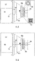
- the transmission range of electrical power from the wireless electrical power transmitter 240 to the wireless electrical power receiver 250 may occur over a distance equivalent to a first transmission range D1, as shown in FIG. 3 .
- the transmission range of electrical power from the wireless electrical power transmitter 240 to the wireless electrical power receiver 250 may occur over a distance equivalent to a second transmission range D2, as shown in FIG. 4.
- the second transmission range D2 is greater than the first transmission range D1.
- the enhancer 300 may be removable from between the wireless electrical power transmitter 240 and the wireless electrical power receiver 250.
- the magnetic field enhancer 300 may be located closer to the wireless electrical power transmitter 240 than the wireless electrical power receiver 250, as shown in FIGs. 4- 6 .
- the magnetic field enhancer 300 may be located closer to the wireless electrical power receiver 250 than the wireless electrical power transmitter 240.
- the magnetic field enhancer 300 is shaped to wrap at least partially around the wireless electrical power transmitter 240, such as, for example, a "C" shape as shown in FIG. 4.
- the magnetic field enhancer 300 is shaped to wrap at least partially around the wireless electrical power receiver 250, such as, for example, a "C" shape.
- the magnetic field enhancer 300 may have a negative refractive index that bends the magnetic field 242 outward to extend the wireless power transfer range.
- the magnetic field enhancer 300 may be composed of a metamaterial block 300a configured to extend the wireless power transfer range.
- the metamaterial block 300a may include at least one of a spiral resonator 310 and a split ring resonator 320.
- the magnetic field enhancer 300 may be also composed of an array of resonators 330 at 300b. The array of resonators 330 are configured to extend the transfer range of wireless electrical power.
- the second transmission range D2 being greater than the first transmission range D1 creates an increased transmission range that allows more time for the transmission of electrical power from the wireless electrical power transmitter 240 to the wireless electrical power receiver 250 as the wireless electrical power receiver 250 moves past the wireless electrical power transmitter 240.
- This increased transmission range allows either more electric power to be transferred or the same electrical power to be transferred.
- the wireless electrical power transmitter 240 of FIG. 3 may only be able to transfer electrical power under static operation (i.e., when the elevator car 103 is stopped), and hence, the charging time during at the elevator landings 125 is limited by the stop time (e.g., about 10 seconds).
- the electrical power transfer can be carried out when the elevator car 103 is approaching and/or leaving the location A1, A2 of the wireless electrical power transmitter 240, thus increasing the total charge time.
- the increased total charge time may reduce the sizing requirements of the energy storage device 270 and also power transfer ratings, thus reducing cost while increasing performance of the wireless power transfer system 200.
- utilizing a magnetic field enhancer 300 can achieve robust wireless power transfer operation under a variation of the airgap sizes and other changing conditions (e.g., load, input voltage) to maintain a desired output to the elevator car 103, which enables efficient operation operations of the elevator system 101 and simplifies installation efforts by allowing larger mechanical tolerances.
Landscapes
- Engineering & Computer Science (AREA)
- Computer Networks & Wireless Communication (AREA)
- Power Engineering (AREA)
- Physics & Mathematics (AREA)
- Electromagnetism (AREA)
- Civil Engineering (AREA)
- Mechanical Engineering (AREA)
- Structural Engineering (AREA)
- Elevator Control (AREA)
- Indicating And Signalling Devices For Elevators (AREA)
Claims (7)
- Drahtloses Leistungsübertragungssystem (200) zum drahtlosen Versorgen einer Beförderungsvorrichtung (103) eines Beförderungssystems (101) mit Leistung, wobei das drahtlose Leistungsübertragungssystem (200) Folgendes umfasst:einen drahtlosen Sender (240) für elektrische Leistung, der sich entlang einer Seite des Beförderungssystems (101) an einer ersten Stelle (A1) befindet, wobei die Seite feststehend ist;einen drahtlosen Empfänger (250) für elektrische Leistung, der sich entlang einer Oberfläche der Beförderungsvorrichtung (103) gegenüber der Seite befindet, wobei der drahtlose Empfänger (250) für elektrische Leistung und der drahtlose Sender (240) für elektrische Leistung in einer einander zugewandten beabstandeten Beziehung stehen, die einen Spalt (G1) dazwischen definiert, wenn sich der drahtlose Empfänger (250) für elektrische Leistung an der ersten Stelle befindet; undeinen Magnetfeldverstärker (300), der sich innerhalb des Spalts (G1) befindet, wobei der Magnetfeldverstärker (300) dazu konfiguriert ist, einen Bereich für die drahtlose Leistungsübertragung des drahtlosen Senders (240) für elektrische Leistung zu erweitern;dadurch gekennzeichnet, dass:
der Magnetfeldverstärker (300) so geformt ist, dass er sich mindestens teilweise um den drahtlosen Sender (240) für elektrische Leistung wickelt, und/oder wobei der Magnetfeldverstärker (300) so geformt ist, dass er sich mindestens teilweise um den drahtlosen Empfänger (250) für elektrische Leistung wickelt. - Drahtloses Leistungsübertragungssystem nach (200) Anspruch 1, wobei das Beförderungssystem (101) ein Aufzugssystem ist und die Beförderungsvorrichtung (103) eine Aufzugskabine ist, wobei optional die Seite eine Wand eines Aufzugsschachts (117) der Aufzugsanlage ist.
- Drahtloses Leistungsübertragungssystem (200) nach Anspruch 1 oder 2, wobei der Magnetfeldverstärker (300) ferner einen Metamaterialblock (300a) umfasst, wobei optional der Metamaterialblock (300a) mindestens einen Spiralresonator und/oder einen Split-Ring-Resonator (320) beinhaltet.
- Drahtloses Leistungsübertragungssystem (200) nach einem vorhergehenden Anspruch, wobei der Magnetfeldverstärker (300) ferner eine Anordnung von Resonatoren (330) umfasst.
- Drahtloses Leistungsübertragungssystem (200) nach einem vorhergehenden Anspruch, wobei der Magnetfeldverstärker (300) sich näher an dem drahtlosen Sender (240) für elektrische Leistung als der drahtlose Empfänger (250) für elektrische Leistung befindet.
- Drahtloses Leistungsübertragungssystem nach einem vorhergehenden Anspruch, wobei der Magnetfeldverstärker (300) sich näher an dem drahtlosen Empfänger (250) für elektrische Leistung als der drahtlose Sender (240) für elektrische Leistung befindet.
- Beförderungssystem (101), umfassendeine Beförderungsvorrichtung (103); undein drahtloses Leistungsübertragungssystem (200) nach einem der Ansprüche 1 bis 6.
Applications Claiming Priority (1)
| Application Number | Priority Date | Filing Date | Title |
|---|---|---|---|
| US201862779511P | 2018-12-14 | 2018-12-14 |
Publications (3)
| Publication Number | Publication Date |
|---|---|
| EP3666714A2 EP3666714A2 (de) | 2020-06-17 |
| EP3666714A3 EP3666714A3 (de) | 2020-06-24 |
| EP3666714B1 true EP3666714B1 (de) | 2023-01-25 |
Family
ID=68886944
Family Applications (1)
| Application Number | Title | Priority Date | Filing Date |
|---|---|---|---|
| EP19215400.3A Active EP3666714B1 (de) | 2018-12-14 | 2019-12-11 | System zur drahtlosen stromübertragung für aufzüge mit erweitertem bereich |
Country Status (3)
| Country | Link |
|---|---|
| US (1) | US11336120B2 (de) |
| EP (1) | EP3666714B1 (de) |
| CN (1) | CN111404287B (de) |
Families Citing this family (1)
| Publication number | Priority date | Publication date | Assignee | Title |
|---|---|---|---|---|
| EP3666703B1 (de) * | 2018-12-14 | 2022-04-06 | Otis Elevator Company | Stromübertragung an aufzugssystemkabinen |
Family Cites Families (15)
| Publication number | Priority date | Publication date | Assignee | Title |
|---|---|---|---|---|
| JP3915414B2 (ja) * | 2001-02-21 | 2007-05-16 | 株式会社日立製作所 | エレベーター |
| US7825543B2 (en) | 2005-07-12 | 2010-11-02 | Massachusetts Institute Of Technology | Wireless energy transfer |
| US8482158B2 (en) | 2008-09-27 | 2013-07-09 | Witricity Corporation | Wireless energy transfer using variable size resonators and system monitoring |
| FI121066B (fi) | 2009-03-31 | 2010-06-30 | Kone Corp | Hissijärjestelmä |
| US20110133568A1 (en) * | 2009-12-03 | 2011-06-09 | Bingnan Wang | Wireless Energy Transfer with Metamaterials |
| US8786135B2 (en) * | 2010-03-25 | 2014-07-22 | Mitsubishi Electric Research Laboratories, Inc. | Wireless energy transfer with anisotropic metamaterials |
| US8994221B2 (en) | 2010-06-01 | 2015-03-31 | University Of Maryland | Method and system for long range wireless power transfer |
| US20120217816A1 (en) * | 2011-02-28 | 2012-08-30 | Bingnan Wang | Wireless Energy Transfer Using Arrays of Resonant Objects |
| US9509179B2 (en) * | 2011-09-13 | 2016-11-29 | Samsung Electronics Co., Ltd. | Wireless electromagnetic receiver and wireless power transfer system |
| CN103296769A (zh) | 2012-02-29 | 2013-09-11 | 深圳光启创新技术有限公司 | 一种无线能量传输系统 |
| US9515492B2 (en) | 2012-12-06 | 2016-12-06 | Toyota Motor Engineering & Manufacturing North America, Inc. | Wireless power transfer using air gap and metamaterial |
| US9369001B2 (en) * | 2013-05-16 | 2016-06-14 | Delphi Technologies, Inc. | Magnetic field detection apparatus for a wireless power transfer system |
| US9837860B2 (en) | 2014-05-05 | 2017-12-05 | Witricity Corporation | Wireless power transmission systems for elevators |
| US10135299B2 (en) | 2015-08-25 | 2018-11-20 | Otis Elevator Company | Elevator wireless power transfer system |
| CN106160255B (zh) | 2016-07-04 | 2019-09-03 | 上海交通大学 | 基于超材料的无线电能传输线圈装置 |
-
2019
- 2019-12-09 US US16/706,966 patent/US11336120B2/en active Active
- 2019-12-11 EP EP19215400.3A patent/EP3666714B1/de active Active
- 2019-12-13 CN CN201911278704.4A patent/CN111404287B/zh not_active Expired - Fee Related
Also Published As
| Publication number | Publication date |
|---|---|
| US20200195053A1 (en) | 2020-06-18 |
| EP3666714A2 (de) | 2020-06-17 |
| EP3666714A3 (de) | 2020-06-24 |
| US11336120B2 (en) | 2022-05-17 |
| CN111404287A (zh) | 2020-07-10 |
| CN111404287B (zh) | 2023-06-06 |
Similar Documents
| Publication | Publication Date | Title |
|---|---|---|
| JP3915414B2 (ja) | エレベーター | |
| CN106487200B (zh) | 具有无线电力传输系统的电磁推进系统 | |
| CN107531445B (zh) | 自行式电梯系统的无线通信 | |
| CN102556786B (zh) | 电梯装置 | |
| EP3431433A2 (de) | Aufzugskabinenenergieversorgungssystem | |
| EP3318527A1 (de) | Autonomes elektrisches aufzugssystem | |
| EP3670417A1 (de) | Drahtloses stromladen von auto zu anrufpunkt | |
| EP3670415A2 (de) | Virtueller sensor zur aufzugsüberwachung | |
| EP3715303B1 (de) | Mehrschächtiges stromladen | |
| US11670961B2 (en) | Closed loop control wireless power transmission system for conveyance system | |
| US11682929B2 (en) | Car to car wireless power transfer | |
| EP3666714B1 (de) | System zur drahtlosen stromübertragung für aufzüge mit erweitertem bereich | |
| US20200131004A1 (en) | Elevator system | |
| JP2001002346A (ja) | ロープ式エレベータ及びロープ式エレベータシステム | |
| CN108778974B (zh) | 电梯短程通信系统 | |
| EP1721856B1 (de) | Aufzugssteuerung | |
| US20200189875A1 (en) | Energy-aware dispatching for conveyance systems | |
| WO2000053520A1 (fr) | Ascenseur | |
| Escalada et al. | Elevators | |
| CN117246878A (zh) | 实施包括并联控制的多个定子的多线性多相感应机械装置的电梯系统 |
Legal Events
| Date | Code | Title | Description |
|---|---|---|---|
| PUAI | Public reference made under article 153(3) epc to a published international application that has entered the european phase |
Free format text: ORIGINAL CODE: 0009012 |
|
| STAA | Information on the status of an ep patent application or granted ep patent |
Free format text: STATUS: THE APPLICATION HAS BEEN PUBLISHED |
|
| PUAL | Search report despatched |
Free format text: ORIGINAL CODE: 0009013 |
|
| AK | Designated contracting states |
Kind code of ref document: A2 Designated state(s): AL AT BE BG CH CY CZ DE DK EE ES FI FR GB GR HR HU IE IS IT LI LT LU LV MC MK MT NL NO PL PT RO RS SE SI SK SM TR |
|
| AX | Request for extension of the european patent |
Extension state: BA ME |
|
| AK | Designated contracting states |
Kind code of ref document: A3 Designated state(s): AL AT BE BG CH CY CZ DE DK EE ES FI FR GB GR HR HU IE IS IT LI LT LU LV MC MK MT NL NO PL PT RO RS SE SI SK SM TR |
|
| AX | Request for extension of the european patent |
Extension state: BA ME |
|
| RIC1 | Information provided on ipc code assigned before grant |
Ipc: B66B 7/00 20060101AFI20200520BHEP |
|
| STAA | Information on the status of an ep patent application or granted ep patent |
Free format text: STATUS: REQUEST FOR EXAMINATION WAS MADE |
|
| 17P | Request for examination filed |
Effective date: 20201222 |
|
| RBV | Designated contracting states (corrected) |
Designated state(s): AL AT BE BG CH CY CZ DE DK EE ES FI FR GB GR HR HU IE IS IT LI LT LU LV MC MK MT NL NO PL PT RO RS SE SI SK SM TR |
|
| GRAP | Despatch of communication of intention to grant a patent |
Free format text: ORIGINAL CODE: EPIDOSNIGR1 |
|
| STAA | Information on the status of an ep patent application or granted ep patent |
Free format text: STATUS: GRANT OF PATENT IS INTENDED |
|
| INTG | Intention to grant announced |
Effective date: 20220623 |
|
| GRAS | Grant fee paid |
Free format text: ORIGINAL CODE: EPIDOSNIGR3 |
|
| GRAA | (expected) grant |
Free format text: ORIGINAL CODE: 0009210 |
|
| STAA | Information on the status of an ep patent application or granted ep patent |
Free format text: STATUS: THE PATENT HAS BEEN GRANTED |
|
| AK | Designated contracting states |
Kind code of ref document: B1 Designated state(s): AL AT BE BG CH CY CZ DE DK EE ES FI FR GB GR HR HU IE IS IT LI LT LU LV MC MK MT NL NO PL PT RO RS SE SI SK SM TR |
|
| REG | Reference to a national code |
Ref country code: GB Ref legal event code: FG4D |
|
| REG | Reference to a national code |
Ref country code: CH Ref legal event code: EP |
|
| REG | Reference to a national code |
Ref country code: AT Ref legal event code: REF Ref document number: 1545796 Country of ref document: AT Kind code of ref document: T Effective date: 20230215 Ref country code: IE Ref legal event code: FG4D |
|
| REG | Reference to a national code |
Ref country code: DE Ref legal event code: R096 Ref document number: 602019024752 Country of ref document: DE |
|
| REG | Reference to a national code |
Ref country code: LT Ref legal event code: MG9D |
|
| REG | Reference to a national code |
Ref country code: NL Ref legal event code: MP Effective date: 20230125 |
|
| REG | Reference to a national code |
Ref country code: AT Ref legal event code: MK05 Ref document number: 1545796 Country of ref document: AT Kind code of ref document: T Effective date: 20230125 |
|
| PG25 | Lapsed in a contracting state [announced via postgrant information from national office to epo] |
Ref country code: NL Free format text: LAPSE BECAUSE OF FAILURE TO SUBMIT A TRANSLATION OF THE DESCRIPTION OR TO PAY THE FEE WITHIN THE PRESCRIBED TIME-LIMIT Effective date: 20230125 |
|
| PG25 | Lapsed in a contracting state [announced via postgrant information from national office to epo] |
Ref country code: RS Free format text: LAPSE BECAUSE OF FAILURE TO SUBMIT A TRANSLATION OF THE DESCRIPTION OR TO PAY THE FEE WITHIN THE PRESCRIBED TIME-LIMIT Effective date: 20230125 Ref country code: PT Free format text: LAPSE BECAUSE OF FAILURE TO SUBMIT A TRANSLATION OF THE DESCRIPTION OR TO PAY THE FEE WITHIN THE PRESCRIBED TIME-LIMIT Effective date: 20230525 Ref country code: NO Free format text: LAPSE BECAUSE OF FAILURE TO SUBMIT A TRANSLATION OF THE DESCRIPTION OR TO PAY THE FEE WITHIN THE PRESCRIBED TIME-LIMIT Effective date: 20230425 Ref country code: LV Free format text: LAPSE BECAUSE OF FAILURE TO SUBMIT A TRANSLATION OF THE DESCRIPTION OR TO PAY THE FEE WITHIN THE PRESCRIBED TIME-LIMIT Effective date: 20230125 Ref country code: LT Free format text: LAPSE BECAUSE OF FAILURE TO SUBMIT A TRANSLATION OF THE DESCRIPTION OR TO PAY THE FEE WITHIN THE PRESCRIBED TIME-LIMIT Effective date: 20230125 Ref country code: HR Free format text: LAPSE BECAUSE OF FAILURE TO SUBMIT A TRANSLATION OF THE DESCRIPTION OR TO PAY THE FEE WITHIN THE PRESCRIBED TIME-LIMIT Effective date: 20230125 Ref country code: ES Free format text: LAPSE BECAUSE OF FAILURE TO SUBMIT A TRANSLATION OF THE DESCRIPTION OR TO PAY THE FEE WITHIN THE PRESCRIBED TIME-LIMIT Effective date: 20230125 Ref country code: AT Free format text: LAPSE BECAUSE OF FAILURE TO SUBMIT A TRANSLATION OF THE DESCRIPTION OR TO PAY THE FEE WITHIN THE PRESCRIBED TIME-LIMIT Effective date: 20230125 |
|
| PG25 | Lapsed in a contracting state [announced via postgrant information from national office to epo] |
Ref country code: SE Free format text: LAPSE BECAUSE OF FAILURE TO SUBMIT A TRANSLATION OF THE DESCRIPTION OR TO PAY THE FEE WITHIN THE PRESCRIBED TIME-LIMIT Effective date: 20230125 Ref country code: PL Free format text: LAPSE BECAUSE OF FAILURE TO SUBMIT A TRANSLATION OF THE DESCRIPTION OR TO PAY THE FEE WITHIN THE PRESCRIBED TIME-LIMIT Effective date: 20230125 Ref country code: IS Free format text: LAPSE BECAUSE OF FAILURE TO SUBMIT A TRANSLATION OF THE DESCRIPTION OR TO PAY THE FEE WITHIN THE PRESCRIBED TIME-LIMIT Effective date: 20230525 Ref country code: GR Free format text: LAPSE BECAUSE OF FAILURE TO SUBMIT A TRANSLATION OF THE DESCRIPTION OR TO PAY THE FEE WITHIN THE PRESCRIBED TIME-LIMIT Effective date: 20230426 Ref country code: FI Free format text: LAPSE BECAUSE OF FAILURE TO SUBMIT A TRANSLATION OF THE DESCRIPTION OR TO PAY THE FEE WITHIN THE PRESCRIBED TIME-LIMIT Effective date: 20230125 |
|
| REG | Reference to a national code |
Ref country code: DE Ref legal event code: R097 Ref document number: 602019024752 Country of ref document: DE |
|
| PG25 | Lapsed in a contracting state [announced via postgrant information from national office to epo] |
Ref country code: SM Free format text: LAPSE BECAUSE OF FAILURE TO SUBMIT A TRANSLATION OF THE DESCRIPTION OR TO PAY THE FEE WITHIN THE PRESCRIBED TIME-LIMIT Effective date: 20230125 Ref country code: RO Free format text: LAPSE BECAUSE OF FAILURE TO SUBMIT A TRANSLATION OF THE DESCRIPTION OR TO PAY THE FEE WITHIN THE PRESCRIBED TIME-LIMIT Effective date: 20230125 Ref country code: EE Free format text: LAPSE BECAUSE OF FAILURE TO SUBMIT A TRANSLATION OF THE DESCRIPTION OR TO PAY THE FEE WITHIN THE PRESCRIBED TIME-LIMIT Effective date: 20230125 Ref country code: DK Free format text: LAPSE BECAUSE OF FAILURE TO SUBMIT A TRANSLATION OF THE DESCRIPTION OR TO PAY THE FEE WITHIN THE PRESCRIBED TIME-LIMIT Effective date: 20230125 Ref country code: CZ Free format text: LAPSE BECAUSE OF FAILURE TO SUBMIT A TRANSLATION OF THE DESCRIPTION OR TO PAY THE FEE WITHIN THE PRESCRIBED TIME-LIMIT Effective date: 20230125 |
|
| PG25 | Lapsed in a contracting state [announced via postgrant information from national office to epo] |
Ref country code: SK Free format text: LAPSE BECAUSE OF FAILURE TO SUBMIT A TRANSLATION OF THE DESCRIPTION OR TO PAY THE FEE WITHIN THE PRESCRIBED TIME-LIMIT Effective date: 20230125 |
|
| PLBE | No opposition filed within time limit |
Free format text: ORIGINAL CODE: 0009261 |
|
| STAA | Information on the status of an ep patent application or granted ep patent |
Free format text: STATUS: NO OPPOSITION FILED WITHIN TIME LIMIT |
|
| 26N | No opposition filed |
Effective date: 20231026 |
|
| PG25 | Lapsed in a contracting state [announced via postgrant information from national office to epo] |
Ref country code: SI Free format text: LAPSE BECAUSE OF FAILURE TO SUBMIT A TRANSLATION OF THE DESCRIPTION OR TO PAY THE FEE WITHIN THE PRESCRIBED TIME-LIMIT Effective date: 20230125 |
|
| PGFP | Annual fee paid to national office [announced via postgrant information from national office to epo] |
Ref country code: FR Payment date: 20231122 Year of fee payment: 5 Ref country code: DE Payment date: 20231121 Year of fee payment: 5 |
|
| PG25 | Lapsed in a contracting state [announced via postgrant information from national office to epo] |
Ref country code: IT Free format text: LAPSE BECAUSE OF FAILURE TO SUBMIT A TRANSLATION OF THE DESCRIPTION OR TO PAY THE FEE WITHIN THE PRESCRIBED TIME-LIMIT Effective date: 20230125 |
|
| REG | Reference to a national code |
Ref country code: CH Ref legal event code: PL |
|
| PG25 | Lapsed in a contracting state [announced via postgrant information from national office to epo] |
Ref country code: LU Free format text: LAPSE BECAUSE OF NON-PAYMENT OF DUE FEES Effective date: 20231211 |
|
| PG25 | Lapsed in a contracting state [announced via postgrant information from national office to epo] |
Ref country code: MC Free format text: LAPSE BECAUSE OF FAILURE TO SUBMIT A TRANSLATION OF THE DESCRIPTION OR TO PAY THE FEE WITHIN THE PRESCRIBED TIME-LIMIT Effective date: 20230125 |
|
| GBPC | Gb: european patent ceased through non-payment of renewal fee |
Effective date: 20231211 |
|
| REG | Reference to a national code |
Ref country code: BE Ref legal event code: MM Effective date: 20231231 |
|
| PG25 | Lapsed in a contracting state [announced via postgrant information from national office to epo] |
Ref country code: MC Free format text: LAPSE BECAUSE OF FAILURE TO SUBMIT A TRANSLATION OF THE DESCRIPTION OR TO PAY THE FEE WITHIN THE PRESCRIBED TIME-LIMIT Effective date: 20230125 Ref country code: LU Free format text: LAPSE BECAUSE OF NON-PAYMENT OF DUE FEES Effective date: 20231211 |
|
| REG | Reference to a national code |
Ref country code: IE Ref legal event code: MM4A |
|
| PG25 | Lapsed in a contracting state [announced via postgrant information from national office to epo] |
Ref country code: IE Free format text: LAPSE BECAUSE OF NON-PAYMENT OF DUE FEES Effective date: 20231211 |
|
| PG25 | Lapsed in a contracting state [announced via postgrant information from national office to epo] |
Ref country code: GB Free format text: LAPSE BECAUSE OF NON-PAYMENT OF DUE FEES Effective date: 20231211 |
|
| PG25 | Lapsed in a contracting state [announced via postgrant information from national office to epo] |
Ref country code: BE Free format text: LAPSE BECAUSE OF NON-PAYMENT OF DUE FEES Effective date: 20231231 |
|
| PG25 | Lapsed in a contracting state [announced via postgrant information from national office to epo] |
Ref country code: CH Free format text: LAPSE BECAUSE OF NON-PAYMENT OF DUE FEES Effective date: 20231231 |
|
| PG25 | Lapsed in a contracting state [announced via postgrant information from national office to epo] |
Ref country code: IE Free format text: LAPSE BECAUSE OF NON-PAYMENT OF DUE FEES Effective date: 20231211 Ref country code: GB Free format text: LAPSE BECAUSE OF NON-PAYMENT OF DUE FEES Effective date: 20231211 Ref country code: CH Free format text: LAPSE BECAUSE OF NON-PAYMENT OF DUE FEES Effective date: 20231231 Ref country code: BE Free format text: LAPSE BECAUSE OF NON-PAYMENT OF DUE FEES Effective date: 20231231 |
|
| PG25 | Lapsed in a contracting state [announced via postgrant information from national office to epo] |
Ref country code: BG Free format text: LAPSE BECAUSE OF FAILURE TO SUBMIT A TRANSLATION OF THE DESCRIPTION OR TO PAY THE FEE WITHIN THE PRESCRIBED TIME-LIMIT Effective date: 20230125 |
|
| PG25 | Lapsed in a contracting state [announced via postgrant information from national office to epo] |
Ref country code: BG Free format text: LAPSE BECAUSE OF FAILURE TO SUBMIT A TRANSLATION OF THE DESCRIPTION OR TO PAY THE FEE WITHIN THE PRESCRIBED TIME-LIMIT Effective date: 20230125 |
|
| REG | Reference to a national code |
Ref country code: DE Ref legal event code: R119 Ref document number: 602019024752 Country of ref document: DE |
|
| PG25 | Lapsed in a contracting state [announced via postgrant information from national office to epo] |
Ref country code: CY Free format text: LAPSE BECAUSE OF FAILURE TO SUBMIT A TRANSLATION OF THE DESCRIPTION OR TO PAY THE FEE WITHIN THE PRESCRIBED TIME-LIMIT; INVALID AB INITIO Effective date: 20191211 |
|
| PG25 | Lapsed in a contracting state [announced via postgrant information from national office to epo] |
Ref country code: HU Free format text: LAPSE BECAUSE OF FAILURE TO SUBMIT A TRANSLATION OF THE DESCRIPTION OR TO PAY THE FEE WITHIN THE PRESCRIBED TIME-LIMIT; INVALID AB INITIO Effective date: 20191211 |
|
| PG25 | Lapsed in a contracting state [announced via postgrant information from national office to epo] |
Ref country code: DE Free format text: LAPSE BECAUSE OF NON-PAYMENT OF DUE FEES Effective date: 20250701 |
|
| PG25 | Lapsed in a contracting state [announced via postgrant information from national office to epo] |
Ref country code: FR Free format text: LAPSE BECAUSE OF NON-PAYMENT OF DUE FEES Effective date: 20241231 |
|
| PG25 | Lapsed in a contracting state [announced via postgrant information from national office to epo] |
Ref country code: TR Free format text: LAPSE BECAUSE OF FAILURE TO SUBMIT A TRANSLATION OF THE DESCRIPTION OR TO PAY THE FEE WITHIN THE PRESCRIBED TIME-LIMIT Effective date: 20230125 |