EP3667020A1 - Agencement d'aube pour turbomachines - Google Patents
Agencement d'aube pour turbomachines Download PDFInfo
- Publication number
- EP3667020A1 EP3667020A1 EP19214170.3A EP19214170A EP3667020A1 EP 3667020 A1 EP3667020 A1 EP 3667020A1 EP 19214170 A EP19214170 A EP 19214170A EP 3667020 A1 EP3667020 A1 EP 3667020A1
- Authority
- EP
- European Patent Office
- Prior art keywords
- blade
- wall
- damper
- platform
- arrangement according
- Prior art date
- Legal status (The legal status is an assumption and is not a legal conclusion. Google has not performed a legal analysis and makes no representation as to the accuracy of the status listed.)
- Pending
Links
Images
Classifications
-
- F—MECHANICAL ENGINEERING; LIGHTING; HEATING; WEAPONS; BLASTING
- F01—MACHINES OR ENGINES IN GENERAL; ENGINE PLANTS IN GENERAL; STEAM ENGINES
- F01D—NON-POSITIVE DISPLACEMENT MACHINES OR ENGINES, e.g. STEAM TURBINES
- F01D5/00—Blades; Blade-carrying members; Heating, heat-insulating, cooling or antivibration means on the blades or the members
- F01D5/12—Blades
- F01D5/22—Blade-to-blade connections, e.g. for damping vibrations
-
- F—MECHANICAL ENGINEERING; LIGHTING; HEATING; WEAPONS; BLASTING
- F01—MACHINES OR ENGINES IN GENERAL; ENGINE PLANTS IN GENERAL; STEAM ENGINES
- F01D—NON-POSITIVE DISPLACEMENT MACHINES OR ENGINES, e.g. STEAM TURBINES
- F01D5/00—Blades; Blade-carrying members; Heating, heat-insulating, cooling or antivibration means on the blades or the members
- F01D5/12—Blades
- F01D5/14—Form or construction
- F01D5/16—Form or construction for counteracting blade vibration
-
- F—MECHANICAL ENGINEERING; LIGHTING; HEATING; WEAPONS; BLASTING
- F05—INDEXING SCHEMES RELATING TO ENGINES OR PUMPS IN VARIOUS SUBCLASSES OF CLASSES F01-F04
- F05D—INDEXING SCHEME FOR ASPECTS RELATING TO NON-POSITIVE-DISPLACEMENT MACHINES OR ENGINES, GAS-TURBINES OR JET-PROPULSION PLANTS
- F05D2220/00—Application
- F05D2220/30—Application in turbines
- F05D2220/32—Application in turbines in gas turbines
-
- F—MECHANICAL ENGINEERING; LIGHTING; HEATING; WEAPONS; BLASTING
- F05—INDEXING SCHEMES RELATING TO ENGINES OR PUMPS IN VARIOUS SUBCLASSES OF CLASSES F01-F04
- F05D—INDEXING SCHEME FOR ASPECTS RELATING TO NON-POSITIVE-DISPLACEMENT MACHINES OR ENGINES, GAS-TURBINES OR JET-PROPULSION PLANTS
- F05D2250/00—Geometry
- F05D2250/20—Three-dimensional
- F05D2250/24—Three-dimensional ellipsoidal
- F05D2250/241—Three-dimensional ellipsoidal spherical
-
- F—MECHANICAL ENGINEERING; LIGHTING; HEATING; WEAPONS; BLASTING
- F05—INDEXING SCHEMES RELATING TO ENGINES OR PUMPS IN VARIOUS SUBCLASSES OF CLASSES F01-F04
- F05D—INDEXING SCHEME FOR ASPECTS RELATING TO NON-POSITIVE-DISPLACEMENT MACHINES OR ENGINES, GAS-TURBINES OR JET-PROPULSION PLANTS
- F05D2260/00—Function
- F05D2260/96—Preventing, counteracting or reducing vibration or noise
Definitions
- the present invention relates to a blade arrangement for a turbomachine, in particular a gas turbine, a turbomachine, in particular a gas turbine, with the blade arrangement and a method for reducing vibrations of the blade arrangement.
- Turbomachinery blades can have different vibration modes during operation.
- so-called flap modes (“F mode”) of the blades can cause the blades or platforms to tilt about the main or rotational axis of the turbomachine, and so-called couple disk modes (“CD mode”) can nod of the blades or platforms in the direction of a dividing line between the platforms.
- F mode flap modes
- CD mode couple disk modes
- An object of an embodiment of the present invention is to reduce blade assembly vibrations.
- one blade arrangement for a or a turbomachine in one embodiment a gas turbine, in particular an aircraft engine, has a blade with an airfoil and at least one platform, as well as one adjacent (arranged) in the circumferential direction.
- a further blade with an airfoil and at least one platform these two blades being referred to as the first and second blades without restriction of generality, their airfoil and their platform accordingly as the first airfoil or first platform (the first blade) or second Blade or second platform (the second blade).
- the blades are rotor blades and / or blades of a compressor or turbine stage of a gas turbine, in particular an aircraft engine, and / or have blade feet which, in particular releasably and / or positively and / or frictionally, in a carrier, in particular a rotor the turbomachine, attached or provided for this purpose, in particular set up, are or are used.
- the present invention can be used here with particular advantage.
- a wall of the first blade and a wall of the second blade delimit a blade cavity in which a one-part or multi-part damper is arranged, which is a wall-side damper Has contact surface, which during operation contacts the first and second wall at least temporarily or is provided for this, in particular set up, is or is used.
- this contact surface has a surface section, which in the present case is referred to as the first surface section without restriction of generality and is convexly curved (seen) in a first direction, in at least one contact position in which this first surface section has the first wall contacted, parallel to at least a portion of an edge, in particular a blade edge or flow channel side or upper edge, of the first platform, which faces the second platform.
- the contact surface has a first surface section which is convexly curved in the direction of at least a section of an edge (facing the airfoil or flow channel or upper) of the first platform or a dividing line between the first and second platforms, when the damper or its first surface portion is in the contact position.
- this section of the edge is at least 10%, in particular at least 25%, in one embodiment at least 50% of a (total) length of the edge or dividing line, it can in particular also be 100%.
- the dividing line can be in the form of a gap, in particular in order to compensate for tolerances, thermal expansions, movements or the like.
- the edge of the first platform (facing the second platform) does not touch the second platform in one embodiment (in (normal) operation) or is provided for this, in particular set up.
- the edge of the first platform (s) facing the second platform and the second platform can touch at least temporarily, so that the dividing line forms a contact line between the first and second platforms.
- the first direction is parallel to at least a section of a dividing line between the first and second platforms, in particular a section of an edge (through the edge facing the second platform) of the first platform) temporary or only virtual or theoretical contact line between the first and second platforms, this section in one embodiment at least 10%, in particular at least 25%, in one embodiment at least 50% of a (total) length of the separation or (temporary or (only) virtual or theoretical) contact line, in particular can also be 100%.
- couple disk modes can cause the blades or platforms to nod in the direction of the dividing line. Because the damper or its contact surface in the first surface section is convexly curved parallel to at least a section of the edge of the first platform facing the second platform or the dividing line defined thereby between the first and second platforms, in one embodiment, a (thereby favored) ) Relative movement of the first and second blades relative to one another is advantageously dissipated by a (thereby favored) frictional sliding movement of the damper or its contact surface and thus corresponding vibrations of the blade arrangements are reduced.
- the first surface section is also convexly curved in the circumferential direction (seen) when the damper is in the contact position.
- flap modes can cause the blades or platforms to tilt about the main or rotational axis or in the circumferential direction. Since the damper or its contact surface in the first surface section is also convexly curved in the circumferential direction, in one embodiment, as a result of a (thereby favored) relative movement of the first and second blades relative to one another, advantageously (due to this) frictional sliding movement of the damper or its contact surface Vibration energy is dissipated and corresponding vibrations of the blade arrangements are reduced.
- the first surface section is straight (seen) in the circumferential direction when the damper is in the contact position.
- a sliding movement between the first surface section and the first wall can be made more difficult or a contact surface can be enlarged and the damper can thereby be better supported on the first wall.
- the contact surface has a further surface section, which is present is referred to without limitation of generality as the second surface section, contacts the second wall when the damper is in the contact position, or is provided for this, in particular is set up, is used, and then or in the contact position in the circumferential direction (viewed) is convexly curved.
- the damper can advantageously be supported on the first wall by the first surface section that is straight in the circumferential direction (seen), the second surface section convexly curved in the circumferential direction (seen) in the contact position is not limited to this, but also in combination with a first surface section which is convexly curved in the circumferential direction (seen) in the contact position, can advantageously reduce vibrations.
- the first surface section convexly curved in the contact position both in the first direction and in the circumferential direction (as seen)
- This second surface section can in particular be flat or planar.
- a sliding movement between this second surface section and the second wall can be made more difficult and the damper can thereby be better supported on the second wall.
- the damper has one or more damper cavities in which (in each case) at least, in a preferred embodiment (in each case) exactly one, in one embodiment spherical, shock body is or will be arranged, which during operation has butt contacts executes the damper cavity wall or provides for this, in particular is set up or used.
- dampers and blades in combination with impulses between shock bodies, dampers and blades can be transmitted in a particularly advantageous manner in combination with the contact surface described above, and blade vibrations can thereby be particularly advantageously reduced. It is assumed that this is particularly favored by the sliding movements in the corresponding directions which are thereby favored or made more difficult, without being bound to this assumption.
- the or one or more of the shock bodies is / are / are arranged airtight or gas-tight in the (respective) damper cavity.
- the or one or more of the damper cavities is / are / are closed (in each case, in particular together) by an airtight cover, which is arranged on a side of the damper opposite the contact surface.
- shock bodies, dampers and blades can be (further) improved in one embodiment.
- the first and second platforms are platforms on the blade root side, in particular thus radially inward and / or sub-platforms.
- the blade cavity is arranged in one embodiment on a side of the first and / or second platform facing away from the blade, in one embodiment entirely or partially in the first and / or second platform.
- an axial direction is parallel to a rotary or (main) machine axis of the turbomachine, corresponding to a circumferential direction a direction of rotation about this axis, a radial direction perpendicular to the axial and circumferential direction.
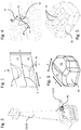
- Fig. 1 shows a blade arrangement according to an embodiment of the present invention in a radial plan view
- Fig. 2 one of the two identical blades of the blade arrangement in a perspective view.
- Both blades each have an airfoil 10 or 20 and a platform 11 or 21 on the blade root side.
- a damper 30 is arranged, on the wall-side contact surface one in Fig. 3 looks.
- This contact surface has a first surface section 31 which is convexly curved in a first direction K, which is in a contact position in which the first Surface section contacts the wall of a blade (cf. Fig. 4 ), parallel to the edge k of the first platform 11 facing the second platform 21 or dividing line between the first and second platforms.
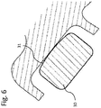
- Fig. 6 shows a section along the in Fig. 4 dash-dotted line VI-VI.
- the first surface section in the contact position is also convexly curved in the circumferential direction U, and the contact surface has a second surface section 32, which contacts the wall of the other blade in the contact position and is straight in the first direction K and in the circumferential direction U.
- the first surface section 31 is straight in the contact position in the circumferential direction U and the second surface section 32 is convexly curved in the circumferential direction.
- the damper 30 has a plurality of damper cavities 33, in each of which one (in Fig. 5 hidden) shock body is arranged for butt contact with the respective damper cavity wall.
- the damper cavities are or are defined by a (in Fig. 5 hidden) cover airtight.
Landscapes
- Engineering & Computer Science (AREA)
- Mechanical Engineering (AREA)
- General Engineering & Computer Science (AREA)
- Structures Of Non-Positive Displacement Pumps (AREA)
Applications Claiming Priority (1)
| Application Number | Priority Date | Filing Date | Title |
|---|---|---|---|
| DE102018221533.2A DE102018221533A1 (de) | 2018-12-12 | 2018-12-12 | Turbomaschinen Schaufelanordnung |
Publications (1)
| Publication Number | Publication Date |
|---|---|
| EP3667020A1 true EP3667020A1 (fr) | 2020-06-17 |
Family
ID=69024093
Family Applications (1)
| Application Number | Title | Priority Date | Filing Date |
|---|---|---|---|
| EP19214170.3A Pending EP3667020A1 (fr) | 2018-12-12 | 2019-12-06 | Agencement d'aube pour turbomachines |
Country Status (3)
| Country | Link |
|---|---|
| US (1) | US11215062B2 (fr) |
| EP (1) | EP3667020A1 (fr) |
| DE (1) | DE102018221533A1 (fr) |
Cited By (3)
| Publication number | Priority date | Publication date | Assignee | Title |
|---|---|---|---|---|
| EP4095411A1 (fr) * | 2021-05-20 | 2022-11-30 | MTU Aero Engines AG | Agencement de réduction d'une vibration |
| EP4095412A1 (fr) * | 2021-05-20 | 2022-11-30 | MTU Aero Engines AG | Agencement de réduction d'une vibration |
| EP3999718B1 (fr) * | 2019-07-19 | 2024-06-12 | MTU Aero Engines AG | Rotor aubagé monobloc de turbomachine |
Families Citing this family (2)
| Publication number | Priority date | Publication date | Assignee | Title |
|---|---|---|---|---|
| DE202021103804U1 (de) | 2021-07-15 | 2021-07-23 | MTU Aero Engines AG | Turbomaschinenschaufel für eine Strömungsmaschine, Impulskörpermodul, Set und Turbomaschine |
| DE202023103424U1 (de) | 2023-06-21 | 2023-06-28 | MTU Aero Engines AG | Reibdämpfer zur Aufnahme in einer Turbomaschinenschaufel für eine Strömungsmaschine |
Citations (9)
| Publication number | Priority date | Publication date | Assignee | Title |
|---|---|---|---|---|
| US4457668A (en) * | 1981-04-07 | 1984-07-03 | S.N.E.C.M.A. | Gas turbine stages of turbojets with devices for the air cooling of the turbine wheel disc |
| EP1600606A1 (fr) * | 2004-05-03 | 2005-11-30 | Rolls-Royce Deutschland Ltd & Co KG | Système d'étanchéité et d'amortissement pour les aubes des turbines à gaz |
| JP2006125372A (ja) * | 2004-11-01 | 2006-05-18 | Mitsubishi Heavy Ind Ltd | 回転機械翼の防振構造および回転機械 |
| EP2163725A2 (fr) * | 2008-09-10 | 2010-03-17 | Rolls-Royce plc | Agencement d'amortisseur de pale de turbine |
| EP2455587A1 (fr) * | 2010-11-17 | 2012-05-23 | MTU Aero Engines GmbH | Rotor de turbomachine, turbomachine et procédé de fabrication associés |
| WO2012095067A1 (fr) | 2010-11-16 | 2012-07-19 | Mtu Aero Engines Gmbh | Aube de turbomachine présentant un élément synchro |
| WO2014051688A1 (fr) * | 2012-09-28 | 2014-04-03 | United Technologies Corporation | Étouffoir doté d'une rétention améliorée |
| EP3098387A1 (fr) * | 2015-05-26 | 2016-11-30 | United Technologies Corporation | Amortisseur à tolérance de pannes d'installation |
| DE102016221069A1 (de) * | 2016-10-26 | 2018-04-26 | MTU Aero Engines AG | Impulskörpermodul mit Lagesicherung |
Family Cites Families (29)
| Publication number | Priority date | Publication date | Assignee | Title |
|---|---|---|---|---|
| US3037741A (en) | 1958-12-29 | 1962-06-05 | Gen Electric | Damping turbine buckets |
| US5302085A (en) * | 1992-02-03 | 1994-04-12 | General Electric Company | Turbine blade damper |
| US5478207A (en) * | 1994-09-19 | 1995-12-26 | General Electric Company | Stable blade vibration damper for gas turbine engine |
| US5749705A (en) * | 1996-10-11 | 1998-05-12 | General Electric Company | Retention system for bar-type damper of rotor blade |
| US5924699A (en) * | 1996-12-24 | 1999-07-20 | United Technologies Corporation | Turbine blade platform seal |
| DE10014198A1 (de) | 2000-03-22 | 2001-09-27 | Alstom Power Nv | Beschaufelung mit Dämpfungselementen |
| US6776583B1 (en) * | 2003-02-27 | 2004-08-17 | General Electric Company | Turbine bucket damper pin |
| US7534090B2 (en) | 2006-06-13 | 2009-05-19 | General Electric Company | Enhanced bucket vibration system |
| JP2008303794A (ja) * | 2007-06-07 | 2008-12-18 | Mitsubishi Heavy Ind Ltd | タービン動翼の振動低減装置 |
| FR2923557B1 (fr) * | 2007-11-12 | 2010-01-22 | Snecma | Ensemble d'une aube de soufflante et de son amortisseur, amortisseur d'aube de soufflante et methode de calibrage de l'amortisseur |
| FR2949142B1 (fr) * | 2009-08-11 | 2011-10-14 | Snecma | Cale amortisseuse de vibrations pour aube de soufflante |
| EP2484870A1 (fr) * | 2011-02-08 | 2012-08-08 | MTU Aero Engines GmbH | Pale de turbomachine comprenant un elément d'amortissement et procédé de conception d'une telle turbomachine |
| DE102010052965B4 (de) * | 2010-11-30 | 2014-06-12 | MTU Aero Engines AG | Dämpfungsmittel zum Dämpfen einer Schaufelbewegung einer Turbomaschine |
| FR2981979B1 (fr) * | 2011-10-28 | 2013-11-29 | Snecma | Roue de turbine pour une turbomachine |
| EP2848770B1 (fr) * | 2013-09-17 | 2017-03-29 | MTU Aero Engines GmbH | Pale de rotor d'une turbomachine axiale et élément d'amortissement |
| US9732620B2 (en) * | 2013-09-26 | 2017-08-15 | United Technologies Corporation | Snap in platform damper and seal assembly for a gas turbine engine |
| DE102014223231B4 (de) * | 2014-11-13 | 2017-09-07 | MTU Aero Engines AG | Turbomaschinenschaufelanordnung |
| EP3023584B1 (fr) * | 2014-11-24 | 2019-07-17 | MTU Aero Engines GmbH | Aube de turbomachine et turbomachine axiale |
| US20170067347A1 (en) * | 2015-09-03 | 2017-03-09 | General Electric Company | Slotted damper pin for a turbine blade |
| US10767504B2 (en) * | 2016-01-12 | 2020-09-08 | Siemens Aktiengesellschaft | Flexible damper for turbine blades |
| EP3219916A1 (fr) * | 2016-03-16 | 2017-09-20 | MTU Aero Engines GmbH | Procédé de fabrication d'un composant de désaccord d'impulsions pour une turbine |
| DE102016204281A1 (de) * | 2016-03-16 | 2017-09-21 | MTU Aero Engines AG | Turbomaschinenschaufelanordnung |
| EP3239461B1 (fr) * | 2016-04-27 | 2021-09-08 | MTU Aero Engines AG | Ensemble de pale de turbomachine |
| DE102016207874A1 (de) * | 2016-05-09 | 2017-11-09 | MTU Aero Engines AG | Impulskörpermodul für eine Strömungsmaschine |
| US10648347B2 (en) * | 2017-01-03 | 2020-05-12 | General Electric Company | Damping inserts and methods for shrouded turbine blades |
| US10731479B2 (en) * | 2017-01-03 | 2020-08-04 | Raytheon Technologies Corporation | Blade platform with damper restraint |
| PL3724453T3 (pl) * | 2017-12-12 | 2026-01-19 | Safran Helicopter Engines | Tłumik drgań dla łopatki wirnika turbomaszyny |
| JP7178874B2 (ja) * | 2018-11-01 | 2022-11-28 | 三菱重工航空エンジン株式会社 | 回転機械の翼の制振装置及びこれを備えた回転機械 |
| JP7267427B2 (ja) * | 2018-12-20 | 2023-05-01 | シーメンス エナジー グローバル ゲゼルシャフト ミット ベシュレンクテル ハフツング ウント コンパニー コマンディートゲゼルシャフト | ブレードロータシステムと対応する保守点検方法 |
-
2018
- 2018-12-12 DE DE102018221533.2A patent/DE102018221533A1/de not_active Withdrawn
-
2019
- 2019-12-06 EP EP19214170.3A patent/EP3667020A1/fr active Pending
- 2019-12-10 US US16/709,515 patent/US11215062B2/en active Active
Patent Citations (9)
| Publication number | Priority date | Publication date | Assignee | Title |
|---|---|---|---|---|
| US4457668A (en) * | 1981-04-07 | 1984-07-03 | S.N.E.C.M.A. | Gas turbine stages of turbojets with devices for the air cooling of the turbine wheel disc |
| EP1600606A1 (fr) * | 2004-05-03 | 2005-11-30 | Rolls-Royce Deutschland Ltd & Co KG | Système d'étanchéité et d'amortissement pour les aubes des turbines à gaz |
| JP2006125372A (ja) * | 2004-11-01 | 2006-05-18 | Mitsubishi Heavy Ind Ltd | 回転機械翼の防振構造および回転機械 |
| EP2163725A2 (fr) * | 2008-09-10 | 2010-03-17 | Rolls-Royce plc | Agencement d'amortisseur de pale de turbine |
| WO2012095067A1 (fr) | 2010-11-16 | 2012-07-19 | Mtu Aero Engines Gmbh | Aube de turbomachine présentant un élément synchro |
| EP2455587A1 (fr) * | 2010-11-17 | 2012-05-23 | MTU Aero Engines GmbH | Rotor de turbomachine, turbomachine et procédé de fabrication associés |
| WO2014051688A1 (fr) * | 2012-09-28 | 2014-04-03 | United Technologies Corporation | Étouffoir doté d'une rétention améliorée |
| EP3098387A1 (fr) * | 2015-05-26 | 2016-11-30 | United Technologies Corporation | Amortisseur à tolérance de pannes d'installation |
| DE102016221069A1 (de) * | 2016-10-26 | 2018-04-26 | MTU Aero Engines AG | Impulskörpermodul mit Lagesicherung |
Cited By (5)
| Publication number | Priority date | Publication date | Assignee | Title |
|---|---|---|---|---|
| EP3999718B1 (fr) * | 2019-07-19 | 2024-06-12 | MTU Aero Engines AG | Rotor aubagé monobloc de turbomachine |
| EP4095411A1 (fr) * | 2021-05-20 | 2022-11-30 | MTU Aero Engines AG | Agencement de réduction d'une vibration |
| EP4095412A1 (fr) * | 2021-05-20 | 2022-11-30 | MTU Aero Engines AG | Agencement de réduction d'une vibration |
| US11898618B2 (en) | 2021-05-20 | 2024-02-13 | MTU Aero Engines AG | Arrangement for reducing oscillation |
| US11905850B2 (en) | 2021-05-20 | 2024-02-20 | MTU Aero Engines AG | Arrangement for reducing oscillation |
Also Published As
| Publication number | Publication date |
|---|---|
| DE102018221533A1 (de) | 2020-06-18 |
| US20200240277A1 (en) | 2020-07-30 |
| US11215062B2 (en) | 2022-01-04 |
Similar Documents
| Publication | Publication Date | Title |
|---|---|---|
| EP3667020A1 (fr) | Agencement d'aube pour turbomachines | |
| DE102011054589B4 (de) | Rotationsmaschine mit Abstandhaltern zur Steuerung der Fluiddynamik | |
| EP3023584B1 (fr) | Aube de turbomachine et turbomachine axiale | |
| DE102007037208B4 (de) | Turbinenschaufel mit zumindest einer Einsatzhülse zum Kühlen der Turbinenschaufel | |
| EP2434098A1 (fr) | Agencement d'aubes et turbine à gaz associée | |
| EP3287611A1 (fr) | Turbine à gaz et procédé de suspension d'un segment d'aube de guidage d'une turbine à gaz | |
| EP2294286A2 (fr) | Carénage pour aubes mobiles d'une turbomachine | |
| EP2378068B1 (fr) | Système d'amortissement pour l'amortissement de vibrations d'une aube rotorique, aube rotorique et rotor associés | |
| EP2884050A1 (fr) | Grille d'aube et procédé associé | |
| DE102023116926A1 (de) | Verschachtelter dämpferstift und schwingungsdämpfungssystem für turbinendüse oder -schaufel | |
| EP3241995B1 (fr) | Segment d'aube directrice pour une turbo-machine | |
| EP3231998A1 (fr) | Segment d'une aube statorique | |
| EP3239461A1 (fr) | Système de pale de turbomachine | |
| EP3056677A1 (fr) | Aube, anneau de renforcement et turbomachine | |
| EP2977554A1 (fr) | Pales de turbomachine desaccordees | |
| EP2977553A1 (fr) | Grille d'aube desaccordée pour une turbomachine | |
| EP3477048B1 (fr) | Agencement d'étanchéité d'une interstice entre aubes de turbomachine et de réduction des vibrations des aubes de turbomachine | |
| EP2578801A1 (fr) | Talons d'aube pour une turbomachine | |
| EP3196413B1 (fr) | Étage de turbomachine | |
| EP3572624B1 (fr) | Module de turbomachine | |
| DE60318852T2 (de) | Apparat und Methode zur Dämpfung von Vibrationen zwischen Kompressorleitschaufeln und dem Gehäuse einer Gasturbine | |
| EP2884049B1 (fr) | Agencement d'aubes mobiles de turbines à gaz avec une tige d'amortissement | |
| EP3623576B1 (fr) | Aube de turbine à gaz | |
| EP3406860A1 (fr) | Turboréacteur | |
| EP3428391A1 (fr) | Grille d'aube d'une turbomachine |
Legal Events
| Date | Code | Title | Description |
|---|---|---|---|
| PUAI | Public reference made under article 153(3) epc to a published international application that has entered the european phase |
Free format text: ORIGINAL CODE: 0009012 |
|
| STAA | Information on the status of an ep patent application or granted ep patent |
Free format text: STATUS: THE APPLICATION HAS BEEN PUBLISHED |
|
| AK | Designated contracting states |
Kind code of ref document: A1 Designated state(s): AL AT BE BG CH CY CZ DE DK EE ES FI FR GB GR HR HU IE IS IT LI LT LU LV MC MK MT NL NO PL PT RO RS SE SI SK SM TR |
|
| AX | Request for extension of the european patent |
Extension state: BA ME |
|
| STAA | Information on the status of an ep patent application or granted ep patent |
Free format text: STATUS: REQUEST FOR EXAMINATION WAS MADE |
|
| 17P | Request for examination filed |
Effective date: 20201215 |
|
| RBV | Designated contracting states (corrected) |
Designated state(s): AL AT BE BG CH CY CZ DE DK EE ES FI FR GB GR HR HU IE IS IT LI LT LU LV MC MK MT NL NO PL PT RO RS SE SI SK SM TR |
|
| STAA | Information on the status of an ep patent application or granted ep patent |
Free format text: STATUS: EXAMINATION IS IN PROGRESS |
|
| 17Q | First examination report despatched |
Effective date: 20210521 |
|
| GRAP | Despatch of communication of intention to grant a patent |
Free format text: ORIGINAL CODE: EPIDOSNIGR1 |
|
| STAA | Information on the status of an ep patent application or granted ep patent |
Free format text: STATUS: GRANT OF PATENT IS INTENDED |
|
| INTG | Intention to grant announced |
Effective date: 20260213 |