EP3667021A2 - Détermination d'un poids de moment d'un composant sur la base de la géométrie de surface mesurée/du modèle solide du composant - Google Patents
Détermination d'un poids de moment d'un composant sur la base de la géométrie de surface mesurée/du modèle solide du composant Download PDFInfo
- Publication number
- EP3667021A2 EP3667021A2 EP19214128.1A EP19214128A EP3667021A2 EP 3667021 A2 EP3667021 A2 EP 3667021A2 EP 19214128 A EP19214128 A EP 19214128A EP 3667021 A2 EP3667021 A2 EP 3667021A2
- Authority
- EP
- European Patent Office
- Prior art keywords
- rotor blade
- component
- weight
- rotor
- moment
- Prior art date
- Legal status (The legal status is an assumption and is not a legal conclusion. Google has not performed a legal analysis and makes no representation as to the accuracy of the status listed.)
- Granted
Links
Images


Classifications
-
- G—PHYSICS
- G01—MEASURING; TESTING
- G01M—TESTING STATIC OR DYNAMIC BALANCE OF MACHINES OR STRUCTURES; TESTING OF STRUCTURES OR APPARATUS, NOT OTHERWISE PROVIDED FOR
- G01M1/00—Testing static or dynamic balance of machines or structures
- G01M1/10—Determining the moment of inertia
-
- F—MECHANICAL ENGINEERING; LIGHTING; HEATING; WEAPONS; BLASTING
- F01—MACHINES OR ENGINES IN GENERAL; ENGINE PLANTS IN GENERAL; STEAM ENGINES
- F01D—NON-POSITIVE DISPLACEMENT MACHINES OR ENGINES, e.g. STEAM TURBINES
- F01D5/00—Blades; Blade-carrying members; Heating, heat-insulating, cooling or antivibration means on the blades or the members
- F01D5/02—Blade-carrying members, e.g. rotors
- F01D5/027—Arrangements for balancing
-
- B—PERFORMING OPERATIONS; TRANSPORTING
- B23—MACHINE TOOLS; METAL-WORKING NOT OTHERWISE PROVIDED FOR
- B23P—METAL-WORKING NOT OTHERWISE PROVIDED FOR; COMBINED OPERATIONS; UNIVERSAL MACHINE TOOLS
- B23P15/00—Making specific metal objects by operations not covered by a single other subclass or a group in this subclass
- B23P15/04—Making specific metal objects by operations not covered by a single other subclass or a group in this subclass turbine or like blades from several pieces
-
- F—MECHANICAL ENGINEERING; LIGHTING; HEATING; WEAPONS; BLASTING
- F01—MACHINES OR ENGINES IN GENERAL; ENGINE PLANTS IN GENERAL; STEAM ENGINES
- F01D—NON-POSITIVE DISPLACEMENT MACHINES OR ENGINES, e.g. STEAM TURBINES
- F01D21/00—Shutting-down of machines or engines, e.g. in emergency; Regulating, controlling, or safety means not otherwise provided for
- F01D21/003—Arrangements for testing or measuring
-
- F—MECHANICAL ENGINEERING; LIGHTING; HEATING; WEAPONS; BLASTING
- F01—MACHINES OR ENGINES IN GENERAL; ENGINE PLANTS IN GENERAL; STEAM ENGINES
- F01D—NON-POSITIVE DISPLACEMENT MACHINES OR ENGINES, e.g. STEAM TURBINES
- F01D5/00—Blades; Blade-carrying members; Heating, heat-insulating, cooling or antivibration means on the blades or the members
- F01D5/30—Fixing blades to rotors; Blade roots ; Blade spacers
-
- F—MECHANICAL ENGINEERING; LIGHTING; HEATING; WEAPONS; BLASTING
- F01—MACHINES OR ENGINES IN GENERAL; ENGINE PLANTS IN GENERAL; STEAM ENGINES
- F01D—NON-POSITIVE DISPLACEMENT MACHINES OR ENGINES, e.g. STEAM TURBINES
- F01D5/00—Blades; Blade-carrying members; Heating, heat-insulating, cooling or antivibration means on the blades or the members
- F01D5/30—Fixing blades to rotors; Blade roots ; Blade spacers
- F01D5/3061—Fixing blades to rotors; Blade roots ; Blade spacers by welding, brazing
-
- F—MECHANICAL ENGINEERING; LIGHTING; HEATING; WEAPONS; BLASTING
- F01—MACHINES OR ENGINES IN GENERAL; ENGINE PLANTS IN GENERAL; STEAM ENGINES
- F01D—NON-POSITIVE DISPLACEMENT MACHINES OR ENGINES, e.g. STEAM TURBINES
- F01D5/00—Blades; Blade-carrying members; Heating, heat-insulating, cooling or antivibration means on the blades or the members
- F01D5/34—Rotor-blade aggregates of unitary construction, e.g. formed of sheet laminae
-
- G—PHYSICS
- G01—MEASURING; TESTING
- G01M—TESTING STATIC OR DYNAMIC BALANCE OF MACHINES OR STRUCTURES; TESTING OF STRUCTURES OR APPARATUS, NOT OTHERWISE PROVIDED FOR
- G01M1/00—Testing static or dynamic balance of machines or structures
- G01M1/12—Static balancing; Determining position of centre of gravity
- G01M1/122—Determining position of centre of gravity
-
- F—MECHANICAL ENGINEERING; LIGHTING; HEATING; WEAPONS; BLASTING
- F05—INDEXING SCHEMES RELATING TO ENGINES OR PUMPS IN VARIOUS SUBCLASSES OF CLASSES F01-F04
- F05D—INDEXING SCHEME FOR ASPECTS RELATING TO NON-POSITIVE-DISPLACEMENT MACHINES OR ENGINES, GAS-TURBINES OR JET-PROPULSION PLANTS
- F05D2220/00—Application
- F05D2220/30—Application in turbines
- F05D2220/36—Application in turbines specially adapted for the fan of turbofan engines
-
- F—MECHANICAL ENGINEERING; LIGHTING; HEATING; WEAPONS; BLASTING
- F05—INDEXING SCHEMES RELATING TO ENGINES OR PUMPS IN VARIOUS SUBCLASSES OF CLASSES F01-F04
- F05D—INDEXING SCHEME FOR ASPECTS RELATING TO NON-POSITIVE-DISPLACEMENT MACHINES OR ENGINES, GAS-TURBINES OR JET-PROPULSION PLANTS
- F05D2270/00—Control
- F05D2270/80—Devices generating input signals, e.g. transducers, sensors, cameras or strain gauges
- F05D2270/804—Optical devices
- F05D2270/8041—Cameras
-
- Y—GENERAL TAGGING OF NEW TECHNOLOGICAL DEVELOPMENTS; GENERAL TAGGING OF CROSS-SECTIONAL TECHNOLOGIES SPANNING OVER SEVERAL SECTIONS OF THE IPC; TECHNICAL SUBJECTS COVERED BY FORMER USPC CROSS-REFERENCE ART COLLECTIONS [XRACs] AND DIGESTS
- Y02—TECHNOLOGIES OR APPLICATIONS FOR MITIGATION OR ADAPTATION AGAINST CLIMATE CHANGE
- Y02T—CLIMATE CHANGE MITIGATION TECHNOLOGIES RELATED TO TRANSPORTATION
- Y02T50/00—Aeronautics or air transport
- Y02T50/60—Efficient propulsion technologies, e.g. for aircraft
Definitions
- This disclosure relates to a determining a moment weight of a component such as, but not limited to, a rotor blade of a turbine engine.
- a moment weight measurement system requires a rotor blade to be properly positioned in a fixture. However, if the rotor blade is improperly positioned, the moment weight measurement system may provide an inaccurate moment weight measurement.
- a method is provided during which surface data is received indicative of a measured surface geometry of a component.
- the surface data is processed to provide model data indicative of a solid model of the component.
- the model data is processed to determine a center of gravity distance of the component.
- a moment weight of the component is determined based on the center of gravity distance of the component and a measured weight of the component. The moment weight is communicated with the component.
- a manufacturing method is provided during which model data is received indicative of a solid model of a rotor blade.
- a center of gravity distance of the rotor blade is determined using the model data.
- a moment weight of the rotor blade is determined based on the center of gravity distance of the rotor blade and a measured weight of the rotor blade.
- a location for the rotor blade to be connected to a rotor hub is determined based on the moment weight. The rotor blade is connected to the rotor hub at the location.
- an inspection method is provided during a weight of a rotor blade is determined to provide a measured weight of the rotor blade.
- a surface geometry of the rotor blade is measured using a surface inspection system to provide surface data indicative of the measured surface geometry.
- Model data is generated based on the surface data, where the model data is indicative of a solid model of the rotor blade.
- a center of gravity distance of the rotor blade is determined using the model data.
- a moment weight of the rotor blade is determined based on the center of gravity distance and the measured weight of the rotor blade. The moment weight is communicated with the rotor blade.
- a surface inspection system may be operated to measure a surface geometry of the component and provide the surface data.
- the surface inspection system may be configured as or otherwise include a coordinate measuring machine.
- the surface inspection system may be configured as or otherwise include a non-contact inspection system.
- the surface inspection system may be configured as or otherwise include a blue-light inspection system.
- the center of gravity distance may be a radial center of gravity distance.
- the moment weight may be a radial moment weight of the component.
- the determining of the moment weight of the component may include multiplying the center of gravity distance of the component by the measured weight of the component.
- a weight of the component may be measured using a scale to provide the measured weight of the component.
- the communicating of the moment weight with the component may include displaying the moment weight on the component.
- the communicating of the moment weight with the component may include electronically linking the moment weight with the component.
- a location for the component to be connected to a rotor hub is determined based on the communicated moment weight.
- the component may be configured as or otherwise include a rotor blade.
- the rotor blade may be connected to the rotor hub at the location.
- the component may be configured as or otherwise include a rotor blade.
- the component may be configured as or otherwise include a fan blade.
- the rotor blade may be configured as or otherwise include a fan blade.
- a surface geometry of the rotor blade may be measured using a surface inspection system to provide surface data indicative of the surface geometry.
- the model data may be generated based on the surface data.
- a weight of the rotor blade may be measured using a scale to provide the measured weight of the rotor blade.
- FIG. 1 is a schematic illustration of a system 10 for use in manufacture of an apparatus such as, but not limited to, a rotor for a turbine engine.
- This system 10 includes a component (e.g., rotor blade) inspection system 12 and an apparatus (e.g., rotor) balancing system 14.
- a component e.g., rotor blade
- an apparatus e.g., rotor
- FIG. 1 is a schematic illustration of a system 10 for use in manufacture of an apparatus such as, but not limited to, a rotor for a turbine engine.
- This system 10 includes a component (e.g., rotor blade) inspection system 12 and an apparatus (e.g., rotor) balancing system 14.
- the component inspection system 12 and the apparatus balancing system 14 are illustrated in FIG. 1 as two separate systems, the present disclosure is not limited to such a configuration.
- the component inspection system 12 and the apparatus balancing system 14 may be configured as a single system or may share
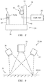
- the component inspection system 12 includes a scale 16, a surface inspection system 18 and a computer 20.
- the scale 16 is configured to measure a weight of a component placed therewith (e.g., thereon).
- Various scale types and configurations are known in the art, and the present disclosure is not limited to any particular ones thereof.
- the surface inspection system 18 is configured to measure (e.g., map) a surface geometry of the component. This surface geometry may represent a select portion of a surface of the component, or an entirety of surface(s) exposed to the surface inspection system 18.
- the surface inspection system 18 may be a contact surface inspection system or a non-contact surface inspection system.
- the term "contact surface inspection system” may describe a surface inspection system that physically contacts a component to measure its surface geometry.
- An example of a contact surface inspection system is a coordinate measuring machine (CMM).
- CCMM coordinate measuring machine
- non-contact surface inspection system may describe a surface inspection system that does not physically contact a component to measure its surface geometry.
- non-contact surface inspection system examples include, but are not limited to, a blue light inspection system (e.g., a blue light optical scanner), a white light inspection system (e.g., a white light optical scanner), a laser inspection system (e.g., a laser scanning device) and a radiological inspection system (e.g., a computed axial tomography scanning (CAT Scan) device).
- a blue light inspection system e.g., a blue light optical scanner
- a white light inspection system e.g., a white light optical scanner
- laser inspection system e.g., a laser scanning device
- radiological inspection system e.g., a computed axial tomography scanning (CAT Scan) device.
- This inspection system 18 configured as a non-contact (e.g., blue or white light) surface inspection system is shown.
- This inspection system 18 includes an electronic measurement device 22 and a support stand 24.
- the electronic measurement device 22 can include a non-contact sensor 26 (e.g., a blue or white light optical scanner) adapted to map at least a portion of a surface 28 of a component 30; e.g., a rotor blade.
- the term "map" is used herein to describe a process of applying a (e.g., high density) triangulated mesh of surface data points to a component surface.
- the non-contact sensor 26 includes a fringe pattern projector 32 and one or more cameras 34.
- the projector 32 is adapted to project a point, line and/or pattern of light (e.g., blue or white light).
- Each camera 34 is adapted to capture an image of the projected light.
- An example of such a projector and cameras is disclosed in U.S. Patent No. 8,111,907 .
- the support stand 24 includes a base 36, a component support 38 and a sensor support 40.
- the component support 38 extends from the base 36 to a component support surface 42.
- the sensor support 40 extends from the base 36 to a first end 44.
- the sensor support 40 includes a sensor mount 46 disposed axially between the base 36 and the first end 44, which connects the non-contact sensor 26 to the sensor support 40.
- the computer 20 is in signal communication (e.g., hardwired and/or wirelessly connected) with the scale 16 and/or the surface inspection system 18 (e.g., the non-contact sensor 26 of FIG. 2 ).
- the computer 20 may be implemented with a combination of hardware and software.
- the hardware may include memory and at least one processing device, which may include one or more single-core and/or multi-core processors.
- the hardware may also or alternatively include analog and/or digital circuitry other than that described above.
- the memory is configured to store software (e.g., program instructions) for execution by the processing device, which software execution may control and/or facilitate performance of one or more operations such as those described in the methods below.
- the memory may be a non-transitory computer readable medium.
- the memory may be configured as or include a volatile memory and/or a nonvolatile memory.
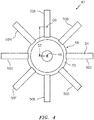
- the apparatus balancing system 14 is configured to determine placement of individual components (e.g., rotor blades) in a rotor 47 (see FIG. 4 ) based on associated component (e.g., rotor blade) moment weights, which rotor 47 is rotatable about a rotational axis 49.
- the apparatus balancing system 14, for example referring to FIG. 4 may be configured to assign rotor blade locations about a rotor disk 48 such that the combined moment weights of the rotor blades 50A-H (generally referred to as "50"), once properly located about and connected to a hub 52 of the rotor disk 48, cancel each other out; e.g., substantially zero out.
- the rotor blade 50A may be diametrically located relative to the rotor blade 50E where those rotor blades 50A and 50E have substantially equal, but opposite acting, moment weights subsequent to being connected to the rotor disk 48.
- Various types and configuration of apparatus balancing systems are known in the art, and the present disclosure is not limited to any particular ones thereof.
- FIG. 5 is a flow diagram of a method 500 utilizing a system such as the system 10 of FIG. 1 .
- the method 500 is described below with reference to the component being a rotor blade 50 and the apparatus being a rotor 47 for ease of description.
- the present disclosure is not limited to any particular component or apparatus types or configurations.
- a weight e.g., a pan weight of the rotor blade 50 is measured.
- the rotor blade 50 may be placed on the scale 16.
- the scale 16 outputs weight data to the computer 20, which weight data is indicative of a measured (e.g., actual, pan) weight of the rotor blade 50.
- the weight of the rotor blade 50 may be determined later in step 508 by processing model data (see step 506) with a known material density and/or other parameter of the rotor blade 50.
- a surface geometry of a surface 54 of the rotor blade 50 is measured (e.g., mapped).
- the surface inspection system 18, for example, may be operated to measure (e.g., map a mesh of coordinates of) at least a portion or an entirety of the rotor blade surface 54.
- the surface inspection system 18 outputs surface data to the computer 20, which surface data is indicative of the measured surface geometry of the rotor blade 50.
- a solid model of the rotor blade 50 is provided.
- This solid model may electronically represent of an entirety (or a portion) of the rotor blade 50.
- the computer 20, for example may be operated to process the surface data with one or more algorithms and/or programs to generate model data indicative of the solid model of the rotor blade 50.
- Various algorithms and programs for generating a solid model based on a surface geometry are known in the art, and the present disclosure is not limited to any particular ones thereof.
- a center of gravity (CG) distance of the rotor blade 50 is determined.
- the term "center of gravity distance” may describe a distance (e.g., distance 57 of FIG. 4 ) between a rotational axis (e.g., the rotational axis 12) and a center of gravity point (CG) of an object (e.g., the rotor blade 50).
- the computer 20, for example may be operated to process the model data and a known material density or other parameter of the rotor blade 50 with one or more algorithms and/or programs to generate CG data indicative of the center of gravity distance of the rotor blade 50.
- Various algorithms and programs for generating a center of gravity based on a solid model and a material density are known in the art, and the present disclosure is not limited to any particular ones thereof.
- a moment weight of the rotor blade 50 is determined.
- the computer 20, for example, may be operated to process the CG data and the weight data to provide moment weight data indicative of the moment weight.
- the computer 20 may multiply the center of gravity distance of the rotor blade 50 by the measured weight of the rotor blade 50 to determine the moment weight of the rotor blade 50.
- the moment weight is associated with (e.g., communicated with and/or assigned to) the rotor blade 50.
- the moment weight may be handwritten, printed and/or otherwise displayed on a root and/or airfoil of the rotor blade 50.
- the moment weight may also or alternatively be displayed on packaging material (e.g., a box or crate) for the rotor blade 50.
- the moment weight may still also or alternatively be electronically associated with the rotor blade 50.
- a rotor blade serial number may be electronically linked with the moment weight.
- a location for the rotor blade 50 to be connected to the rotor hub 52 is determined.
- the apparatus balancing system 14 receives the moment weight data associated with the rotor blade 50, as well as moment weight data associated with other rotor blades 50.
- the moment weight associated with the rotor blade 50, as well as the moment weights associated with other rotor blades 50 may be input into the apparatus balancing system 14.
- the moment weight data / moment weights associated with other rotor blades 50 may be determined and provided to the apparatus balancing system 14 following additional iterations of steps 502, 504, 506, 508, 510 and 512 for the other rotor blades 50.
- the apparatus balancing system 14 processes the received moment weight data / moment weights with one or more algorithms and/or programs to determine locations at which the rotor blades 50 may be connected to the hub 52 such that the rotor 47 is rotationally balanced (as much as possible) during rotor rotation.
- the apparatus balancing system 14 then provides (e.g., outputs data indicative of, displays, etc.) the locations associated with each of the rotor blades 50.
- each of the rotor blades 50 (represented by the moment weight data / moment weights processed by the apparatus balancing system 14) is connected to the rotor hub 52 at a respective one of the locations determined in the balancing step 514.
- These connections may be mechanical connections (e.g., dovetail blade root into corresponding slot in the hub 52) or bonded connections in the case of an integrally bladed rotor (IBR) (also referred to as a "blisk”) for example.
- IBR integrally bladed rotor
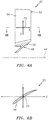
- a moment weight of each rotor blade 50 may be categorized into three components: an axial moment weight (e.g., along x-axis); a tangential moment weight (e.g., along y-axis); and a radial moment weight (e.g., along z-axis).
- the axial moment weight is measured along the rotational axis 49 of the rotor 47.
- the tangential moment weight is measured in a direction than is tangent to a circle around the rotational axis 49.
- the radial moment weight is measure along a ray projecting out from the rotational axis 49 of the rotor 47.
- the method 500 above may be performed for all three components of the moment weight.
- the method 500 may be performed for a single one (or select two) of the three components of the moment weight.
- the moment weight determined in the step 510 may be a radial moment weight.
- the center of gravity distance determined in the step 508 may be a radial center of gravity distance.
- a radial moment weight of a rotor blade is typically significantly larger than an axial or a tangential moment weight of the same rotor blade. Therefore, focusing the method 500 on the radial moment weight may reduce complexity while still providing accurate results.
- the rotor blade 50 may be any type of rotor blade included in a turbine engine.
- the rotor blade 50 for example, may be configured as a fan blade, a compressor blade or a turbine blade.
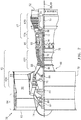
- FIG. 7 is a side cutaway illustration of a geared turbofan turbine engine 56 in which the rotor blade 50 or rotor blades 50 involved in the method 500 may be included.
- This turbine engine 56 extends along an axial centerline 58, which may be coaxial with the rotational axis 49 (see FIG. 4 ), between an upstream airflow inlet 60 and a downstream airflow exhaust 62.
- the turbine engine 56 includes a fan section 64, a compressor section 65, a combustor section 66 and a turbine section 67.
- the compressor section 65 includes a low pressure compressor (LPC) section 65A and a high pressure compressor (HPC) section 65B.
- the turbine section 67 includes a high pressure turbine (HPT) section 67A and a low pressure turbine (LPT) section 67B.
- the engine sections 64-67 are arranged sequentially along the centerline 58 within an engine housing 68.
- This housing 68 includes an inner case 70 (e.g., a core case) and an outer case 72 (e.g., a fan case).
- the inner case 70 may house one or more of the engine sections 65A-67B; e.g., an engine core.
- the outer case 72 may house at least the fan section 64.
- Each of the engine sections 64, 65A, 65B, 67A and 67B includes a respective rotor 74-78; e.g., see FIG. 1 .
- Each of these rotors 74-78 includes a plurality of rotor blades arranged circumferentially around and connected to one or more respective rotor disks.
- the rotor blades may be formed integral with or mechanically fastened, welded, brazed, adhered and/or otherwise attached to the respective rotor disk(s).
- the fan rotor 74 is connected to a gear train 80, for example, through a fan shaft 82.
- the gear train 80 and the LPC rotor 75 are connected to and driven by the LPT rotor 78 through a low speed shaft 83.
- the HPC rotor 76 is connected to and driven by the HPT rotor 77 through a high speed shaft 84.
- the shafts 82-84 are rotatably supported by a plurality of bearings 86; e.g., rolling element and/or thrust bearings. Each of these bearings 86 is connected to the engine housing 68 by at least one stationary structure such as, for example, an annular support strut.
- This air is directed through the fan section 64 and into a core gas path 88 and a bypass gas path 90.
- the core gas path 88 extends sequentially through the engine sections 65A-67B.
- the air within the core gas path 88 may be referred to as "core air”.
- the bypass gas path 90 extends through a bypass duct, which bypasses the engine core.
- the air within the bypass gas path 90 may be referred to as "bypass air”.
- the core air is compressed by the compressor rotors 75 and 76 and directed into a combustion chamber 92 of a combustor in the combustor section 66.
- Fuel is injected into the combustion chamber 92 and mixed with the compressed core air to provide a fuel-air mixture.
- This fuel air mixture is ignited and combustion products thereof flow through and sequentially cause the turbine rotors 77 and 78 to rotate.
- the rotation of the turbine rotors 77 and 78 respectively drive rotation of the compressor rotors 76 and 75 and, thus, compression of the air received from a core airflow inlet.
- the rotation of the turbine rotor 78 also drives rotation of the fan rotor 74, which propels bypass air through and out of the bypass gas path 90.
- the propulsion of the bypass air may account for a majority of thrust generated by the turbine engine 56, e.g., more than seventy-five percent (75%) of engine thrust.
- the turbine engine 56 of the present disclosure is not limited to the foregoing exemplary thrust ratio.
- the rotor 47 and its rotor blades 50 may be included in various turbine engines other than the one described above as well as in other types of rotational equipment.
- the rotor 47 and its rotor blades 50 may be included in a geared turbine engine where a gear train connects one or more shafts to one or more rotors in a fan section, a compressor section and/or any other engine section.
- rotor 47 and its rotor blades 50 may be included in a turbine engine configured without a gear train.
- the rotor 47 and its rotor blades 50 may be included in a geared or non-geared turbine engine configured with a single spool, with two spools (e.g., see FIG.
- the turbine engine may be configured as a turbofan engine, a turbojet engine, a propfan engine, a pusher fan engine or any other type of turbine engine.
- the present disclosure therefore is not limited to any particular types or configurations of turbine engines or other equipment.
Landscapes
- Engineering & Computer Science (AREA)
- Mechanical Engineering (AREA)
- General Engineering & Computer Science (AREA)
- Physics & Mathematics (AREA)
- General Physics & Mathematics (AREA)
- Aviation & Aerospace Engineering (AREA)
- Ceramic Engineering (AREA)
- Turbine Rotor Nozzle Sealing (AREA)
- Testing Of Balance (AREA)
- Measurement Of The Respiration, Hearing Ability, Form, And Blood Characteristics Of Living Organisms (AREA)
- Length Measuring Devices With Unspecified Measuring Means (AREA)
Priority Applications (1)
| Application Number | Priority Date | Filing Date | Title |
|---|---|---|---|
| EP23198930.2A EP4273369B1 (fr) | 2018-12-07 | 2019-12-06 | Détermination d'un poids de moment d'un composant sur la base de la géométrie de surface mesurée/du modèle solide du composant |
Applications Claiming Priority (1)
| Application Number | Priority Date | Filing Date | Title |
|---|---|---|---|
| US16/213,270 US10816429B2 (en) | 2018-12-07 | 2018-12-07 | Determining a moment weight of a component based on measured surface geometry/solid model of the component |
Related Child Applications (2)
| Application Number | Title | Priority Date | Filing Date |
|---|---|---|---|
| EP23198930.2A Division EP4273369B1 (fr) | 2018-12-07 | 2019-12-06 | Détermination d'un poids de moment d'un composant sur la base de la géométrie de surface mesurée/du modèle solide du composant |
| EP23198930.2A Division-Into EP4273369B1 (fr) | 2018-12-07 | 2019-12-06 | Détermination d'un poids de moment d'un composant sur la base de la géométrie de surface mesurée/du modèle solide du composant |
Publications (4)
| Publication Number | Publication Date |
|---|---|
| EP3667021A2 true EP3667021A2 (fr) | 2020-06-17 |
| EP3667021A3 EP3667021A3 (fr) | 2020-08-26 |
| EP3667021B1 EP3667021B1 (fr) | 2023-10-18 |
| EP3667021B8 EP3667021B8 (fr) | 2023-11-22 |
Family
ID=68808178
Family Applications (2)
| Application Number | Title | Priority Date | Filing Date |
|---|---|---|---|
| EP23198930.2A Active EP4273369B1 (fr) | 2018-12-07 | 2019-12-06 | Détermination d'un poids de moment d'un composant sur la base de la géométrie de surface mesurée/du modèle solide du composant |
| EP19214128.1A Active EP3667021B8 (fr) | 2018-12-07 | 2019-12-06 | Détermination d'un poids de moment d'un composant sur la base de la géométrie de surface mesurée/du modèle solide du composant |
Family Applications Before (1)
| Application Number | Title | Priority Date | Filing Date |
|---|---|---|---|
| EP23198930.2A Active EP4273369B1 (fr) | 2018-12-07 | 2019-12-06 | Détermination d'un poids de moment d'un composant sur la base de la géométrie de surface mesurée/du modèle solide du composant |
Country Status (2)
| Country | Link |
|---|---|
| US (1) | US10816429B2 (fr) |
| EP (2) | EP4273369B1 (fr) |
Cited By (1)
| Publication number | Priority date | Publication date | Assignee | Title |
|---|---|---|---|---|
| EP4359648B1 (fr) * | 2021-06-21 | 2024-12-04 | Safran Aircraft Engines | Procédé d'équilibrage d'aubes de soufflante avec usinage du bord de fuite |
Families Citing this family (6)
| Publication number | Priority date | Publication date | Assignee | Title |
|---|---|---|---|---|
| KR20220141817A (ko) * | 2020-01-20 | 2022-10-20 | 블레이드 다이아그노스틱스 코포레이션 | 블레이드 일체형 로터의 자동 유지를 위한 기술 |
| CN112097974A (zh) * | 2020-09-18 | 2020-12-18 | 魏丽蓉 | 一种汽轮机动叶片的力矩测试方法及装置 |
| CN113778039B (zh) * | 2021-11-11 | 2022-02-18 | 中国航发沈阳黎明航空发动机有限责任公司 | 一种基于特征的整体叶盘加工参数优化及质量控制方法 |
| US12163897B2 (en) * | 2022-03-23 | 2024-12-10 | Rtx Corporation | Multi-stage inspection systems and methods |
| US20230304476A1 (en) * | 2022-03-23 | 2023-09-28 | Raytheon Technologies Corporation | Feedback inspection systems and methods |
| US20230305156A1 (en) * | 2022-03-23 | 2023-09-28 | Raytheon Technologies Corporation | Dual scanner inspection systems and methods |
Citations (1)
| Publication number | Priority date | Publication date | Assignee | Title |
|---|---|---|---|---|
| US8111907B2 (en) | 2007-07-31 | 2012-02-07 | United Technologies Corporation | Method for repeatable optical determination of object geometry dimensions and deviations |
Family Cites Families (16)
| Publication number | Priority date | Publication date | Assignee | Title |
|---|---|---|---|---|
| JPS59128414U (ja) | 1983-02-18 | 1984-08-29 | スズキ株式会社 | 自動車の幌布屋根 |
| JPS6441603A (en) * | 1987-08-04 | 1989-02-13 | Sumitomo Heavy Industries | Optimum arranging method for turbine blade on disc by computer simulation |
| US5195363A (en) | 1991-08-16 | 1993-03-23 | The Babcock & Wilcox Company | Automated mass-moment weighing system for jet engine blades |
| WO2003012368A1 (fr) * | 2001-07-30 | 2003-02-13 | Topcon Corporation | Appareil de mesure d'une forme superficielle, procede de mesure d'une forme superficielle et appareil graphique destine a l'etat superficiel |
| FR2842571B1 (fr) * | 2002-07-17 | 2004-10-15 | Snecma Moteurs | Procede de repartition d'aubes de rotor de turbomachine |
| US6908285B2 (en) | 2003-04-08 | 2005-06-21 | General Electric Company | Methods and apparatus for assembling rotatable machines |
| US7090464B2 (en) * | 2004-07-13 | 2006-08-15 | General Electric Company | Methods and apparatus for assembling rotatable machines |
| US7572101B2 (en) | 2005-02-22 | 2009-08-11 | General Electric Company | Methods and apparatus for assembling rotatable machines |
| US7497662B2 (en) | 2006-07-31 | 2009-03-03 | General Electric Company | Methods and systems for assembling rotatable machines |
| DE102007045300A1 (de) | 2007-09-21 | 2009-04-09 | Mtu Aero Engines Gmbh | Verfahren zum Herstellen eines Gasturbinenrotors |
| US8069707B2 (en) | 2009-08-05 | 2011-12-06 | General Electric Company | Methods and apparatus for determining moment weight of rotating machine components |
| GB201009216D0 (en) * | 2010-06-02 | 2010-07-21 | Rolls Royce Plc | Rotationally balancing a rotating part |
| GB2481582A (en) * | 2010-06-28 | 2012-01-04 | Rolls Royce Plc | A method for predicting initial unbalance in a component such as a blisk |
| US20140166373A1 (en) | 2012-12-19 | 2014-06-19 | General Electric Company | Extendable moment weight tools |
| JP6441603B2 (ja) | 2014-07-25 | 2018-12-19 | キユーピー株式会社 | ジュール加熱装置の温度調整器具及びジュール加熱装置 |
| FR3037111B1 (fr) * | 2015-06-08 | 2017-05-19 | Snecma | Procede de fabrication d'une soufflante de turbomachine ayant un niveau de bruit reduit a des frequences multiples de rotation de ladite turbomachine |
-
2018
- 2018-12-07 US US16/213,270 patent/US10816429B2/en active Active
-
2019
- 2019-12-06 EP EP23198930.2A patent/EP4273369B1/fr active Active
- 2019-12-06 EP EP19214128.1A patent/EP3667021B8/fr active Active
Patent Citations (1)
| Publication number | Priority date | Publication date | Assignee | Title |
|---|---|---|---|---|
| US8111907B2 (en) | 2007-07-31 | 2012-02-07 | United Technologies Corporation | Method for repeatable optical determination of object geometry dimensions and deviations |
Cited By (1)
| Publication number | Priority date | Publication date | Assignee | Title |
|---|---|---|---|---|
| EP4359648B1 (fr) * | 2021-06-21 | 2024-12-04 | Safran Aircraft Engines | Procédé d'équilibrage d'aubes de soufflante avec usinage du bord de fuite |
Also Published As
| Publication number | Publication date |
|---|---|
| US10816429B2 (en) | 2020-10-27 |
| EP4273369A2 (fr) | 2023-11-08 |
| US20200182731A1 (en) | 2020-06-11 |
| EP3667021A3 (fr) | 2020-08-26 |
| EP3667021B1 (fr) | 2023-10-18 |
| EP3667021B8 (fr) | 2023-11-22 |
| EP4273369A3 (fr) | 2023-11-15 |
| EP4273369B1 (fr) | 2025-07-30 |
Similar Documents
| Publication | Publication Date | Title |
|---|---|---|
| EP3667021B1 (fr) | Détermination d'un poids de moment d'un composant sur la base de la géométrie de surface mesurée/du modèle solide du composant | |
| JP6335252B2 (ja) | ガスタービンエンジン内のプローブの位置を標定するためのシステムおよび方法 | |
| EP3663516B1 (fr) | Inspection de composants utilisant des poids actuels mesurés et théoriques | |
| EP3623788B1 (fr) | Système de classement de détresse automatisé | |
| US12345167B2 (en) | System and method of using a tool assembly | |
| EP4249727B1 (fr) | Montage d'outil à profil aérodynamique | |
| EP4249731A1 (fr) | Systèmes et procédés d'inspection à plusieurs étages | |
| US11740189B2 (en) | Defining parameters for scan of single crystal structure | |
| EP4269753A1 (fr) | Systèmes et procédés d'inspection pour sceller des surfaces | |
| US20200311908A1 (en) | Systems and methods for inspecting bristles using a digital camera | |
| US20230304476A1 (en) | Feedback inspection systems and methods | |
| US11243158B2 (en) | Determining presence of internal corrosion within a rotor blade by measuring magnetic characteristic(s) | |
| US20240230448A1 (en) | Computationally balancing a rotating structure | |
| EP4311915A1 (fr) | Exécution d'une classification d'aubes directrices pour des moteurs à turbine à l'aide de balayages tridimensionnels à lumière structurée | |
| US20250250029A1 (en) | System and method for validating aircraft propulsion system parts | |
| US20230305156A1 (en) | Dual scanner inspection systems and methods | |
| JP2025158932A (ja) | ターボ機械用の犠牲温度クーポン |
Legal Events
| Date | Code | Title | Description |
|---|---|---|---|
| PUAI | Public reference made under article 153(3) epc to a published international application that has entered the european phase |
Free format text: ORIGINAL CODE: 0009012 |
|
| STAA | Information on the status of an ep patent application or granted ep patent |
Free format text: STATUS: THE APPLICATION HAS BEEN PUBLISHED |
|
| AK | Designated contracting states |
Kind code of ref document: A2 Designated state(s): AL AT BE BG CH CY CZ DE DK EE ES FI FR GB GR HR HU IE IS IT LI LT LU LV MC MK MT NL NO PL PT RO RS SE SI SK SM TR |
|
| AX | Request for extension of the european patent |
Extension state: BA ME |
|
| REG | Reference to a national code |
Ref legal event code: R079 Ipc: F01D0005020000 Ref country code: DE Ref legal event code: R079 Ref document number: 602019039509 Country of ref document: DE Free format text: PREVIOUS MAIN CLASS: F01D0005300000 Ipc: F01D0005020000 |
|
| PUAL | Search report despatched |
Free format text: ORIGINAL CODE: 0009013 |
|
| AK | Designated contracting states |
Kind code of ref document: A3 Designated state(s): AL AT BE BG CH CY CZ DE DK EE ES FI FR GB GR HR HU IE IS IT LI LT LU LV MC MK MT NL NO PL PT RO RS SE SI SK SM TR |
|
| AX | Request for extension of the european patent |
Extension state: BA ME |
|
| RIC1 | Information provided on ipc code assigned before grant |
Ipc: G01M 1/12 20060101ALI20200721BHEP Ipc: F01D 5/30 20060101ALI20200721BHEP Ipc: F01D 21/00 20060101ALI20200721BHEP Ipc: F01D 5/02 20060101AFI20200721BHEP Ipc: F01D 5/34 20060101ALI20200721BHEP |
|
| STAA | Information on the status of an ep patent application or granted ep patent |
Free format text: STATUS: REQUEST FOR EXAMINATION WAS MADE |
|
| RAP1 | Party data changed (applicant data changed or rights of an application transferred) |
Owner name: RAYTHEON TECHNOLOGIES CORPORATION |
|
| 17P | Request for examination filed |
Effective date: 20210224 |
|
| RBV | Designated contracting states (corrected) |
Designated state(s): AL AT BE BG CH CY CZ DE DK EE ES FI FR GB GR HR HU IE IS IT LI LT LU LV MC MK MT NL NO PL PT RO RS SE SI SK SM TR |
|
| GRAP | Despatch of communication of intention to grant a patent |
Free format text: ORIGINAL CODE: EPIDOSNIGR1 |
|
| STAA | Information on the status of an ep patent application or granted ep patent |
Free format text: STATUS: GRANT OF PATENT IS INTENDED |
|
| INTG | Intention to grant announced |
Effective date: 20221108 |
|
| RIN1 | Information on inventor provided before grant (corrected) |
Inventor name: PICKENS, JOHN T. |
|
| GRAJ | Information related to disapproval of communication of intention to grant by the applicant or resumption of examination proceedings by the epo deleted |
Free format text: ORIGINAL CODE: EPIDOSDIGR1 |
|
| STAA | Information on the status of an ep patent application or granted ep patent |
Free format text: STATUS: REQUEST FOR EXAMINATION WAS MADE |
|
| GRAP | Despatch of communication of intention to grant a patent |
Free format text: ORIGINAL CODE: EPIDOSNIGR1 |
|
| STAA | Information on the status of an ep patent application or granted ep patent |
Free format text: STATUS: GRANT OF PATENT IS INTENDED |
|
| GRAJ | Information related to disapproval of communication of intention to grant by the applicant or resumption of examination proceedings by the epo deleted |
Free format text: ORIGINAL CODE: EPIDOSDIGR1 |
|
| GRAJ | Information related to disapproval of communication of intention to grant by the applicant or resumption of examination proceedings by the epo deleted |
Free format text: ORIGINAL CODE: EPIDOSDIGR1 |
|
| GRAP | Despatch of communication of intention to grant a patent |
Free format text: ORIGINAL CODE: EPIDOSNIGR1 |
|
| STAA | Information on the status of an ep patent application or granted ep patent |
Free format text: STATUS: REQUEST FOR EXAMINATION WAS MADE |
|
| INTC | Intention to grant announced (deleted) | ||
| GRAP | Despatch of communication of intention to grant a patent |
Free format text: ORIGINAL CODE: EPIDOSNIGR1 |
|
| STAA | Information on the status of an ep patent application or granted ep patent |
Free format text: STATUS: GRANT OF PATENT IS INTENDED |
|
| INTG | Intention to grant announced |
Effective date: 20230418 |
|
| INTG | Intention to grant announced |
Effective date: 20230509 |
|
| GRAS | Grant fee paid |
Free format text: ORIGINAL CODE: EPIDOSNIGR3 |
|
| GRAA | (expected) grant |
Free format text: ORIGINAL CODE: 0009210 |
|
| STAA | Information on the status of an ep patent application or granted ep patent |
Free format text: STATUS: THE PATENT HAS BEEN GRANTED |
|
| AK | Designated contracting states |
Kind code of ref document: B1 Designated state(s): AL AT BE BG CH CY CZ DE DK EE ES FI FR GB GR HR HU IE IS IT LI LT LU LV MC MK MT NL NO PL PT RO RS SE SI SK SM TR |
|
| REG | Reference to a national code |
Ref country code: GB Ref legal event code: FG4D |
|
| REG | Reference to a national code |
Ref country code: CH Ref legal event code: PK Free format text: BERICHTIGUNG B8 Ref country code: CH Ref legal event code: EP |
|
| RAP4 | Party data changed (patent owner data changed or rights of a patent transferred) |
Owner name: RTX CORPORATION |
|
| REG | Reference to a national code |
Ref country code: IE Ref legal event code: FG4D |
|
| REG | Reference to a national code |
Ref country code: DE Ref legal event code: R096 Ref document number: 602019039509 Country of ref document: DE |
|
| REG | Reference to a national code |
Ref country code: LT Ref legal event code: MG9D |
|
| REG | Reference to a national code |
Ref country code: NL Ref legal event code: MP Effective date: 20231018 |
|
| REG | Reference to a national code |
Ref country code: AT Ref legal event code: MK05 Ref document number: 1622652 Country of ref document: AT Kind code of ref document: T Effective date: 20231018 |
|
| PG25 | Lapsed in a contracting state [announced via postgrant information from national office to epo] |
Ref country code: NL Free format text: LAPSE BECAUSE OF FAILURE TO SUBMIT A TRANSLATION OF THE DESCRIPTION OR TO PAY THE FEE WITHIN THE PRESCRIBED TIME-LIMIT Effective date: 20231018 |
|
| PG25 | Lapsed in a contracting state [announced via postgrant information from national office to epo] |
Ref country code: GR Free format text: LAPSE BECAUSE OF FAILURE TO SUBMIT A TRANSLATION OF THE DESCRIPTION OR TO PAY THE FEE WITHIN THE PRESCRIBED TIME-LIMIT Effective date: 20240119 |
|
| PG25 | Lapsed in a contracting state [announced via postgrant information from national office to epo] |
Ref country code: IS Free format text: LAPSE BECAUSE OF FAILURE TO SUBMIT A TRANSLATION OF THE DESCRIPTION OR TO PAY THE FEE WITHIN THE PRESCRIBED TIME-LIMIT Effective date: 20240218 |
|
| PG25 | Lapsed in a contracting state [announced via postgrant information from national office to epo] |
Ref country code: LT Free format text: LAPSE BECAUSE OF FAILURE TO SUBMIT A TRANSLATION OF THE DESCRIPTION OR TO PAY THE FEE WITHIN THE PRESCRIBED TIME-LIMIT Effective date: 20231018 |
|
| PG25 | Lapsed in a contracting state [announced via postgrant information from national office to epo] |
Ref country code: AT Free format text: LAPSE BECAUSE OF FAILURE TO SUBMIT A TRANSLATION OF THE DESCRIPTION OR TO PAY THE FEE WITHIN THE PRESCRIBED TIME-LIMIT Effective date: 20231018 |
|
| PG25 | Lapsed in a contracting state [announced via postgrant information from national office to epo] |
Ref country code: ES Free format text: LAPSE BECAUSE OF FAILURE TO SUBMIT A TRANSLATION OF THE DESCRIPTION OR TO PAY THE FEE WITHIN THE PRESCRIBED TIME-LIMIT Effective date: 20231018 |
|
| PG25 | Lapsed in a contracting state [announced via postgrant information from national office to epo] |
Ref country code: LT Free format text: LAPSE BECAUSE OF FAILURE TO SUBMIT A TRANSLATION OF THE DESCRIPTION OR TO PAY THE FEE WITHIN THE PRESCRIBED TIME-LIMIT Effective date: 20231018 Ref country code: IS Free format text: LAPSE BECAUSE OF FAILURE TO SUBMIT A TRANSLATION OF THE DESCRIPTION OR TO PAY THE FEE WITHIN THE PRESCRIBED TIME-LIMIT Effective date: 20240218 Ref country code: GR Free format text: LAPSE BECAUSE OF FAILURE TO SUBMIT A TRANSLATION OF THE DESCRIPTION OR TO PAY THE FEE WITHIN THE PRESCRIBED TIME-LIMIT Effective date: 20240119 Ref country code: ES Free format text: LAPSE BECAUSE OF FAILURE TO SUBMIT A TRANSLATION OF THE DESCRIPTION OR TO PAY THE FEE WITHIN THE PRESCRIBED TIME-LIMIT Effective date: 20231018 Ref country code: BG Free format text: LAPSE BECAUSE OF FAILURE TO SUBMIT A TRANSLATION OF THE DESCRIPTION OR TO PAY THE FEE WITHIN THE PRESCRIBED TIME-LIMIT Effective date: 20240118 Ref country code: AT Free format text: LAPSE BECAUSE OF FAILURE TO SUBMIT A TRANSLATION OF THE DESCRIPTION OR TO PAY THE FEE WITHIN THE PRESCRIBED TIME-LIMIT Effective date: 20231018 Ref country code: PT Free format text: LAPSE BECAUSE OF FAILURE TO SUBMIT A TRANSLATION OF THE DESCRIPTION OR TO PAY THE FEE WITHIN THE PRESCRIBED TIME-LIMIT Effective date: 20240219 |
|
| PG25 | Lapsed in a contracting state [announced via postgrant information from national office to epo] |
Ref country code: SE Free format text: LAPSE BECAUSE OF FAILURE TO SUBMIT A TRANSLATION OF THE DESCRIPTION OR TO PAY THE FEE WITHIN THE PRESCRIBED TIME-LIMIT Effective date: 20231018 Ref country code: RS Free format text: LAPSE BECAUSE OF FAILURE TO SUBMIT A TRANSLATION OF THE DESCRIPTION OR TO PAY THE FEE WITHIN THE PRESCRIBED TIME-LIMIT Effective date: 20231018 Ref country code: PL Free format text: LAPSE BECAUSE OF FAILURE TO SUBMIT A TRANSLATION OF THE DESCRIPTION OR TO PAY THE FEE WITHIN THE PRESCRIBED TIME-LIMIT Effective date: 20231018 Ref country code: NO Free format text: LAPSE BECAUSE OF FAILURE TO SUBMIT A TRANSLATION OF THE DESCRIPTION OR TO PAY THE FEE WITHIN THE PRESCRIBED TIME-LIMIT Effective date: 20240118 Ref country code: LV Free format text: LAPSE BECAUSE OF FAILURE TO SUBMIT A TRANSLATION OF THE DESCRIPTION OR TO PAY THE FEE WITHIN THE PRESCRIBED TIME-LIMIT Effective date: 20231018 Ref country code: HR Free format text: LAPSE BECAUSE OF FAILURE TO SUBMIT A TRANSLATION OF THE DESCRIPTION OR TO PAY THE FEE WITHIN THE PRESCRIBED TIME-LIMIT Effective date: 20231018 |
|
| PG25 | Lapsed in a contracting state [announced via postgrant information from national office to epo] |
Ref country code: DK Free format text: LAPSE BECAUSE OF FAILURE TO SUBMIT A TRANSLATION OF THE DESCRIPTION OR TO PAY THE FEE WITHIN THE PRESCRIBED TIME-LIMIT Effective date: 20231018 |
|
| REG | Reference to a national code |
Ref country code: DE Ref legal event code: R097 Ref document number: 602019039509 Country of ref document: DE |
|
| PG25 | Lapsed in a contracting state [announced via postgrant information from national office to epo] |
Ref country code: CZ Free format text: LAPSE BECAUSE OF FAILURE TO SUBMIT A TRANSLATION OF THE DESCRIPTION OR TO PAY THE FEE WITHIN THE PRESCRIBED TIME-LIMIT Effective date: 20231018 |
|
| PG25 | Lapsed in a contracting state [announced via postgrant information from national office to epo] |
Ref country code: SK Free format text: LAPSE BECAUSE OF FAILURE TO SUBMIT A TRANSLATION OF THE DESCRIPTION OR TO PAY THE FEE WITHIN THE PRESCRIBED TIME-LIMIT Effective date: 20231018 |
|
| PG25 | Lapsed in a contracting state [announced via postgrant information from national office to epo] |
Ref country code: SM Free format text: LAPSE BECAUSE OF FAILURE TO SUBMIT A TRANSLATION OF THE DESCRIPTION OR TO PAY THE FEE WITHIN THE PRESCRIBED TIME-LIMIT Effective date: 20231018 Ref country code: SK Free format text: LAPSE BECAUSE OF FAILURE TO SUBMIT A TRANSLATION OF THE DESCRIPTION OR TO PAY THE FEE WITHIN THE PRESCRIBED TIME-LIMIT Effective date: 20231018 Ref country code: RO Free format text: LAPSE BECAUSE OF FAILURE TO SUBMIT A TRANSLATION OF THE DESCRIPTION OR TO PAY THE FEE WITHIN THE PRESCRIBED TIME-LIMIT Effective date: 20231018 Ref country code: IT Free format text: LAPSE BECAUSE OF FAILURE TO SUBMIT A TRANSLATION OF THE DESCRIPTION OR TO PAY THE FEE WITHIN THE PRESCRIBED TIME-LIMIT Effective date: 20231018 Ref country code: EE Free format text: LAPSE BECAUSE OF FAILURE TO SUBMIT A TRANSLATION OF THE DESCRIPTION OR TO PAY THE FEE WITHIN THE PRESCRIBED TIME-LIMIT Effective date: 20231018 Ref country code: DK Free format text: LAPSE BECAUSE OF FAILURE TO SUBMIT A TRANSLATION OF THE DESCRIPTION OR TO PAY THE FEE WITHIN THE PRESCRIBED TIME-LIMIT Effective date: 20231018 Ref country code: CZ Free format text: LAPSE BECAUSE OF FAILURE TO SUBMIT A TRANSLATION OF THE DESCRIPTION OR TO PAY THE FEE WITHIN THE PRESCRIBED TIME-LIMIT Effective date: 20231018 |
|
| REG | Reference to a national code |
Ref country code: CH Ref legal event code: PL |
|
| PLBE | No opposition filed within time limit |
Free format text: ORIGINAL CODE: 0009261 |
|
| STAA | Information on the status of an ep patent application or granted ep patent |
Free format text: STATUS: NO OPPOSITION FILED WITHIN TIME LIMIT |
|
| PG25 | Lapsed in a contracting state [announced via postgrant information from national office to epo] |
Ref country code: LU Free format text: LAPSE BECAUSE OF NON-PAYMENT OF DUE FEES Effective date: 20231206 |
|
| PG25 | Lapsed in a contracting state [announced via postgrant information from national office to epo] |
Ref country code: MC Free format text: LAPSE BECAUSE OF FAILURE TO SUBMIT A TRANSLATION OF THE DESCRIPTION OR TO PAY THE FEE WITHIN THE PRESCRIBED TIME-LIMIT Effective date: 20231018 |
|
| REG | Reference to a national code |
Ref country code: BE Ref legal event code: MM Effective date: 20231231 |
|
| PG25 | Lapsed in a contracting state [announced via postgrant information from national office to epo] |
Ref country code: MC Free format text: LAPSE BECAUSE OF FAILURE TO SUBMIT A TRANSLATION OF THE DESCRIPTION OR TO PAY THE FEE WITHIN THE PRESCRIBED TIME-LIMIT Effective date: 20231018 Ref country code: LU Free format text: LAPSE BECAUSE OF NON-PAYMENT OF DUE FEES Effective date: 20231206 |
|
| 26N | No opposition filed |
Effective date: 20240719 |
|
| REG | Reference to a national code |
Ref country code: IE Ref legal event code: MM4A |
|
| PG25 | Lapsed in a contracting state [announced via postgrant information from national office to epo] |
Ref country code: IE Free format text: LAPSE BECAUSE OF NON-PAYMENT OF DUE FEES Effective date: 20231206 |
|
| PG25 | Lapsed in a contracting state [announced via postgrant information from national office to epo] |
Ref country code: BE Free format text: LAPSE BECAUSE OF NON-PAYMENT OF DUE FEES Effective date: 20231231 |
|
| PG25 | Lapsed in a contracting state [announced via postgrant information from national office to epo] |
Ref country code: CH Free format text: LAPSE BECAUSE OF NON-PAYMENT OF DUE FEES Effective date: 20231231 |
|
| PG25 | Lapsed in a contracting state [announced via postgrant information from national office to epo] |
Ref country code: SI Free format text: LAPSE BECAUSE OF FAILURE TO SUBMIT A TRANSLATION OF THE DESCRIPTION OR TO PAY THE FEE WITHIN THE PRESCRIBED TIME-LIMIT Effective date: 20231018 |
|
| PG25 | Lapsed in a contracting state [announced via postgrant information from national office to epo] |
Ref country code: SI Free format text: LAPSE BECAUSE OF FAILURE TO SUBMIT A TRANSLATION OF THE DESCRIPTION OR TO PAY THE FEE WITHIN THE PRESCRIBED TIME-LIMIT Effective date: 20231018 Ref country code: IE Free format text: LAPSE BECAUSE OF NON-PAYMENT OF DUE FEES Effective date: 20231206 Ref country code: CH Free format text: LAPSE BECAUSE OF NON-PAYMENT OF DUE FEES Effective date: 20231231 Ref country code: BE Free format text: LAPSE BECAUSE OF NON-PAYMENT OF DUE FEES Effective date: 20231231 |
|
| PG25 | Lapsed in a contracting state [announced via postgrant information from national office to epo] |
Ref country code: FI Free format text: LAPSE BECAUSE OF FAILURE TO SUBMIT A TRANSLATION OF THE DESCRIPTION OR TO PAY THE FEE WITHIN THE PRESCRIBED TIME-LIMIT Effective date: 20231019 |
|
| PG25 | Lapsed in a contracting state [announced via postgrant information from national office to epo] |
Ref country code: CY Free format text: LAPSE BECAUSE OF FAILURE TO SUBMIT A TRANSLATION OF THE DESCRIPTION OR TO PAY THE FEE WITHIN THE PRESCRIBED TIME-LIMIT; INVALID AB INITIO Effective date: 20191206 |
|
| PG25 | Lapsed in a contracting state [announced via postgrant information from national office to epo] |
Ref country code: HU Free format text: LAPSE BECAUSE OF FAILURE TO SUBMIT A TRANSLATION OF THE DESCRIPTION OR TO PAY THE FEE WITHIN THE PRESCRIBED TIME-LIMIT; INVALID AB INITIO Effective date: 20191206 |
|
| REG | Reference to a national code |
Ref country code: DE Ref legal event code: R081 Ref document number: 602019039509 Country of ref document: DE Owner name: RTX CORPORATION (N.D.GES.D. STAATES DELAWARE),, US Free format text: FORMER OWNER: RAYTHEON TECHNOLOGIES CORPORATION, FARMINGTON, CT, US |
|
| PG25 | Lapsed in a contracting state [announced via postgrant information from national office to epo] |
Ref country code: TR Free format text: LAPSE BECAUSE OF FAILURE TO SUBMIT A TRANSLATION OF THE DESCRIPTION OR TO PAY THE FEE WITHIN THE PRESCRIBED TIME-LIMIT Effective date: 20231018 |
|
| PGFP | Annual fee paid to national office [announced via postgrant information from national office to epo] |
Ref country code: DE Payment date: 20251126 Year of fee payment: 7 |
|
| PGFP | Annual fee paid to national office [announced via postgrant information from national office to epo] |
Ref country code: GB Payment date: 20251119 Year of fee payment: 7 |
|
| PGFP | Annual fee paid to national office [announced via postgrant information from national office to epo] |
Ref country code: FR Payment date: 20251120 Year of fee payment: 7 |
|
| P01 | Opt-out of the competence of the unified patent court (upc) registered |
Free format text: CASE NUMBER: UPC_APP_0019002_3667021/2025 Effective date: 20251222 |