EP3667023B1 - Pale de distributeur de turbine comportant un réseau de passage de refroidissement doté de guides d'écoulement - Google Patents
Pale de distributeur de turbine comportant un réseau de passage de refroidissement doté de guides d'écoulement Download PDFInfo
- Publication number
- EP3667023B1 EP3667023B1 EP19215753.5A EP19215753A EP3667023B1 EP 3667023 B1 EP3667023 B1 EP 3667023B1 EP 19215753 A EP19215753 A EP 19215753A EP 3667023 B1 EP3667023 B1 EP 3667023B1
- Authority
- EP
- European Patent Office
- Prior art keywords
- flow
- flow guides
- region
- turbine vane
- airfoil
- Prior art date
- Legal status (The legal status is an assumption and is not a legal conclusion. Google has not performed a legal analysis and makes no representation as to the accuracy of the status listed.)
- Active
Links
Images


Classifications
-
- F—MECHANICAL ENGINEERING; LIGHTING; HEATING; WEAPONS; BLASTING
- F01—MACHINES OR ENGINES IN GENERAL; ENGINE PLANTS IN GENERAL; STEAM ENGINES
- F01D—NON-POSITIVE DISPLACEMENT MACHINES OR ENGINES, e.g. STEAM TURBINES
- F01D9/00—Stators
- F01D9/02—Nozzles; Nozzle boxes; Stator blades; Guide conduits, e.g. individual nozzles
- F01D9/04—Nozzles; Nozzle boxes; Stator blades; Guide conduits, e.g. individual nozzles forming ring or sector
- F01D9/041—Nozzles; Nozzle boxes; Stator blades; Guide conduits, e.g. individual nozzles forming ring or sector using blades
-
- F—MECHANICAL ENGINEERING; LIGHTING; HEATING; WEAPONS; BLASTING
- F01—MACHINES OR ENGINES IN GENERAL; ENGINE PLANTS IN GENERAL; STEAM ENGINES
- F01D—NON-POSITIVE DISPLACEMENT MACHINES OR ENGINES, e.g. STEAM TURBINES
- F01D5/00—Blades; Blade-carrying members; Heating, heat-insulating, cooling or antivibration means on the blades or the members
- F01D5/12—Blades
- F01D5/14—Form or construction
- F01D5/18—Hollow blades, i.e. blades with cooling or heating channels or cavities; Heating, heat-insulating or cooling means on blades
- F01D5/187—Convection cooling
- F01D5/188—Convection cooling with an insert in the blade cavity to guide the cooling fluid, e.g. forming a separation wall
- F01D5/189—Convection cooling with an insert in the blade cavity to guide the cooling fluid, e.g. forming a separation wall the insert having a tubular cross-section, e.g. airfoil shape
-
- F—MECHANICAL ENGINEERING; LIGHTING; HEATING; WEAPONS; BLASTING
- F01—MACHINES OR ENGINES IN GENERAL; ENGINE PLANTS IN GENERAL; STEAM ENGINES
- F01D—NON-POSITIVE DISPLACEMENT MACHINES OR ENGINES, e.g. STEAM TURBINES
- F01D25/00—Component parts, details, or accessories, not provided for in, or of interest apart from, other groups
- F01D25/08—Cooling; Heating; Heat-insulation
- F01D25/12—Cooling
-
- F—MECHANICAL ENGINEERING; LIGHTING; HEATING; WEAPONS; BLASTING
- F01—MACHINES OR ENGINES IN GENERAL; ENGINE PLANTS IN GENERAL; STEAM ENGINES
- F01D—NON-POSITIVE DISPLACEMENT MACHINES OR ENGINES, e.g. STEAM TURBINES
- F01D5/00—Blades; Blade-carrying members; Heating, heat-insulating, cooling or antivibration means on the blades or the members
- F01D5/12—Blades
- F01D5/14—Form or construction
- F01D5/147—Construction, i.e. structural features, e.g. of weight-saving hollow blades
-
- F—MECHANICAL ENGINEERING; LIGHTING; HEATING; WEAPONS; BLASTING
- F01—MACHINES OR ENGINES IN GENERAL; ENGINE PLANTS IN GENERAL; STEAM ENGINES
- F01D—NON-POSITIVE DISPLACEMENT MACHINES OR ENGINES, e.g. STEAM TURBINES
- F01D5/00—Blades; Blade-carrying members; Heating, heat-insulating, cooling or antivibration means on the blades or the members
- F01D5/12—Blades
- F01D5/14—Form or construction
- F01D5/18—Hollow blades, i.e. blades with cooling or heating channels or cavities; Heating, heat-insulating or cooling means on blades
- F01D5/187—Convection cooling
-
- F—MECHANICAL ENGINEERING; LIGHTING; HEATING; WEAPONS; BLASTING
- F05—INDEXING SCHEMES RELATING TO ENGINES OR PUMPS IN VARIOUS SUBCLASSES OF CLASSES F01-F04
- F05D—INDEXING SCHEME FOR ASPECTS RELATING TO NON-POSITIVE-DISPLACEMENT MACHINES OR ENGINES, GAS-TURBINES OR JET-PROPULSION PLANTS
- F05D2240/00—Components
- F05D2240/10—Stators
- F05D2240/12—Fluid guiding means, e.g. vanes
-
- F—MECHANICAL ENGINEERING; LIGHTING; HEATING; WEAPONS; BLASTING
- F05—INDEXING SCHEMES RELATING TO ENGINES OR PUMPS IN VARIOUS SUBCLASSES OF CLASSES F01-F04
- F05D—INDEXING SCHEME FOR ASPECTS RELATING TO NON-POSITIVE-DISPLACEMENT MACHINES OR ENGINES, GAS-TURBINES OR JET-PROPULSION PLANTS
- F05D2240/00—Components
- F05D2240/10—Stators
- F05D2240/12—Fluid guiding means, e.g. vanes
- F05D2240/126—Baffles or ribs
-
- F—MECHANICAL ENGINEERING; LIGHTING; HEATING; WEAPONS; BLASTING
- F05—INDEXING SCHEMES RELATING TO ENGINES OR PUMPS IN VARIOUS SUBCLASSES OF CLASSES F01-F04
- F05D—INDEXING SCHEME FOR ASPECTS RELATING TO NON-POSITIVE-DISPLACEMENT MACHINES OR ENGINES, GAS-TURBINES OR JET-PROPULSION PLANTS
- F05D2260/00—Function
- F05D2260/20—Heat transfer, e.g. cooling
- F05D2260/201—Heat transfer, e.g. cooling by impingement of a fluid
-
- F—MECHANICAL ENGINEERING; LIGHTING; HEATING; WEAPONS; BLASTING
- F05—INDEXING SCHEMES RELATING TO ENGINES OR PUMPS IN VARIOUS SUBCLASSES OF CLASSES F01-F04
- F05D—INDEXING SCHEME FOR ASPECTS RELATING TO NON-POSITIVE-DISPLACEMENT MACHINES OR ENGINES, GAS-TURBINES OR JET-PROPULSION PLANTS
- F05D2260/00—Function
- F05D2260/20—Heat transfer, e.g. cooling
- F05D2260/204—Heat transfer, e.g. cooling by the use of microcircuits
-
- F—MECHANICAL ENGINEERING; LIGHTING; HEATING; WEAPONS; BLASTING
- F05—INDEXING SCHEMES RELATING TO ENGINES OR PUMPS IN VARIOUS SUBCLASSES OF CLASSES F01-F04
- F05D—INDEXING SCHEME FOR ASPECTS RELATING TO NON-POSITIVE-DISPLACEMENT MACHINES OR ENGINES, GAS-TURBINES OR JET-PROPULSION PLANTS
- F05D2260/00—Function
- F05D2260/20—Heat transfer, e.g. cooling
- F05D2260/221—Improvement of heat transfer
- F05D2260/2214—Improvement of heat transfer by increasing the heat transfer surface
-
- F—MECHANICAL ENGINEERING; LIGHTING; HEATING; WEAPONS; BLASTING
- F05—INDEXING SCHEMES RELATING TO ENGINES OR PUMPS IN VARIOUS SUBCLASSES OF CLASSES F01-F04
- F05D—INDEXING SCHEME FOR ASPECTS RELATING TO NON-POSITIVE-DISPLACEMENT MACHINES OR ENGINES, GAS-TURBINES OR JET-PROPULSION PLANTS
- F05D2260/00—Function
- F05D2260/20—Heat transfer, e.g. cooling
- F05D2260/221—Improvement of heat transfer
- F05D2260/2214—Improvement of heat transfer by increasing the heat transfer surface
- F05D2260/22141—Improvement of heat transfer by increasing the heat transfer surface using fins or ribs
-
- Y—GENERAL TAGGING OF NEW TECHNOLOGICAL DEVELOPMENTS; GENERAL TAGGING OF CROSS-SECTIONAL TECHNOLOGIES SPANNING OVER SEVERAL SECTIONS OF THE IPC; TECHNICAL SUBJECTS COVERED BY FORMER USPC CROSS-REFERENCE ART COLLECTIONS [XRACs] AND DIGESTS
- Y02—TECHNOLOGIES OR APPLICATIONS FOR MITIGATION OR ADAPTATION AGAINST CLIMATE CHANGE
- Y02T—CLIMATE CHANGE MITIGATION TECHNOLOGIES RELATED TO TRANSPORTATION
- Y02T50/00—Aeronautics or air transport
- Y02T50/60—Efficient propulsion technologies, e.g. for aircraft
Definitions
- a gas turbine engine typically includes a fan section, a compressor section, a combustor section and a turbine section having a turbine vane including cooling passages. Air entering the compressor section is compressed and delivered into the combustion section where it is mixed with fuel and ignited to generate a high-speed exhaust gas flow. The high-speed exhaust gas flow expands through the turbine section to drive the compressor and the fan section.
- the compressor section typically includes low and high pressure compressors, and the turbine section includes low and high pressure turbines.
- the high pressure turbine drives the high pressure compressor through an outer shaft to form a high spool
- the low pressure turbine drives the low pressure compressor through an inner shaft to form a low spool.
- the fan section may also be driven by the low inner shaft.
- a direct drive gas turbine engine includes a fan section driven by the low spool such that the low pressure compressor, low pressure turbine and fan section rotate at a common speed in a common direction.
- EP 0896 127 A2 discloses a prior art turbine vane as set forth in the preamble of claim 1.
- EP 3 196 410 A1 discloses prior art turbine endwall and tip cooling for dual wall airfoils.
- EP 2 489 838 A2 discloses a prior art cooled component for the turbine of a gas turbine engine.
- EP 2 586 981 A2 discloses a prior art gas turbine engine component having wavy cooling channels with pedestals.
- US 4 474 532 A discloses a prior art coolable airfoil for a rotary machine.
- US 5 772 397 A discloses a prior art gas turbine airfoil with aft internal cooling.
- EP 1 091 092 A2 discloses a prior art method and apparatus for cooling a wall within a gas turbine engine.
- EP 1 505 256 A2 discloses prior art microcircuit cooling for a turbine blade.
- US 6 056 505 A discloses prior art cooling circuits for trailing edge cavities in airfoils.
- FIG. 1 schematically illustrates a gas turbine engine 20.
- the gas turbine engine 20 is disclosed herein as a two-spool turbofan that generally incorporates a fan section 22, a compressor section 24, a combustor section 26 and a turbine section 28.
- the fan section 22 drives air along a bypass flow path B in a bypass duct defined within a nacelle 15, and also drives air along a core flow path C for compression and communication into the combustor section 26 then expansion through the turbine section 28.
- FIG. 1 schematically illustrates a gas turbine engine 20.
- the gas turbine engine 20 is disclosed herein as a two-spool turbofan that generally incorporates a fan section 22, a compressor section 24, a combustor section 26 and a turbine section 28.
- the fan section 22 drives air along a bypass flow path B in a bypass duct defined within a nacelle 15, and also drives air along a core flow path C for compression and communication into the combustor section 26 then expansion through the turbine section 28.
- FIG. 1 schematic
- the exemplary engine 20 generally includes a low speed spool 30 and a high speed spool 32 mounted for rotation about an engine central longitudinal axis A relative to an engine static structure 36 via several bearing systems 38. It should be understood that various bearing systems 38 at various locations may alternatively or additionally be provided, and the location of bearing systems 38 may be varied as appropriate to the application.
- the low speed spool 30 generally includes an inner shaft 40 that interconnects, a first (or low) pressure compressor 44 and a first (or low) pressure turbine 46.
- the inner shaft 40 is connected to the fan 42 through a speed change mechanism, which in exemplary gas turbine engine 20 is illustrated as a geared architecture 48 to drive a fan 42 at a lower speed than the low speed spool 30.
- the high speed spool 32 includes an outer shaft 50 that interconnects a second (or high) pressure compressor 52 and a second (or high) pressure turbine 54.
- a combustor 56 is arranged in exemplary gas turbine 20 between the high pressure compressor 52 and the high pressure turbine 54.
- a mid-turbine frame 57 of the engine static structure 36 may be arranged generally between the high pressure turbine 54 and the low pressure turbine 46.
- the mid-turbine frame 57 further supports bearing systems 38 in the turbine section 28.
- the inner shaft 40 and the outer shaft 50 are concentric and rotate via bearing systems 38 about the engine central longitudinal axis A which is colline
- the core airflow is compressed by the low pressure compressor 44 then the high pressure compressor 52, mixed and burned with fuel in the combustor 56, then expanded over the high pressure turbine 54 and low pressure turbine 46.
- the mid-turbine frame 57 includes airfoils 59 which are in the core airflow path C.
- the turbines 46, 54 rotationally drive the respective low speed spool 30 and high speed spool 32 in response to the expansion.
- gear system 48 may be located aft of the low pressure compressor, or aft of the combustor section 26 or even aft of turbine section 28, and fan 42 may be positioned forward or aft of the location of gear system 48.
- the engine 20 in one example is a high-bypass geared aircraft engine.
- the engine 20 bypass ratio is greater than about six (6), with an example embodiment being greater than about ten (10)
- the geared architecture 48 is an epicyclic gear train, such as a planetary gear system or other gear system, with a gear reduction ratio of greater than about 2.3 and the low pressure turbine 46 has a pressure ratio that is greater than about five.
- the engine 20 bypass ratio is greater than about ten (10:1)
- the fan diameter is significantly larger than that of the low pressure compressor 44
- the low pressure turbine 46 has a pressure ratio that is greater than about five (5:1).
- Low pressure turbine 46 pressure ratio is pressure measured prior to inlet of low pressure turbine 46 as related to the pressure at the outlet of the low pressure turbine 46 prior to an exhaust nozzle.
- the geared architecture 48 may be an epicycle gear train, such as a planetary gear system or other gear system, with a gear reduction ratio of greater than about 2.3:1 and less than about 5:1. It should be understood, however, that the above parameters are only exemplary of one embodiment of a geared architecture engine and that the present invention is applicable to other gas turbine engines including direct drive turbofans.
- the fan section 22 of the engine 20 is designed for a particular flight condition -- typically cruise at about 0.8 Mach and about 35,000 feet (10,668 meters).
- the flight condition of 0.8 Mach and 35,000 ft (10,668 meters), with the engine at its best fuel consumption - also known as "bucket cruise Thrust Specific Fuel Consumption ('TSFC')" - is the industry standard parameter of lbm of fuel being burned divided by lbf of thrust the engine produces at that minimum point.
- "Low fan pressure ratio” is the pressure ratio across the fan blade alone, without a Fan Exit Guide Vane (“FEGV”) system.
- the low fan pressure ratio as disclosed herein according to one non-limiting embodiment is less than about 1.45.
- the "Low corrected fan tip speed” as disclosed herein according to one non-limiting embodiment is less than about 1150 ft / second (350.5 meters/second).
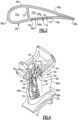
- Figure 2 illustrates a representative example of a turbine airfoil 60 used in the turbine engine 20 (see also Figure 1 ), Figure 3 shows a sectioned view of the airfoil 60, and Figure 4 shows a partial cutaway view of the airfoil 60.
- the turbine airfoil 60 is a turbine vane.
- the turbine airfoil 60 of the turbine vane according to the present invention includes an inner or first platform 62, an outer or second platform 64, and an airfoil section 66 that radially spans between the inner and outer platforms 62/64.
- Terms such as “radially,” “axially,” or variations thereof are used herein to designate directionality with respect to the engine central axis A.
- the airfoil section 66 includes an airfoil outer wall 68 that delimits the profile of the airfoil section 66.
- the outer wall 68 defines a leading end 68a, a trailing end 68b, and first and second sides 68c/68d that join the leading and trailing ends 68a/68b.
- the first and second sides 68c/68d span in a longitudinal direction, denoted by axis A1 (which is also a radial direction relative to the engine central axis A), between first and second ends 68e/68f.
- the first and second ends 68e/68f are attached, respectively, to the first and second platforms 62/64.
- the first side 68c is a suction side
- the second side 68d is a pressure side.
- the outer wall 68 of the airfoil section 66 circumscribes an internal core cavity 70.
- the airfoil section 66 further includes a rib 72 in the internal core cavity 70.
- the rib 72 partitions the internal core cavity 70, dividing the cavity 70 into a forward cavity 70a and an aft cavity 70b.
- the rib 72 extends from the first side 68c to the second side 68d and is solid and free of any orifices. The rib 72 thereby fluidly isolates the forward and aft cavities 70a/70b of the internal core cavity 70.
- cooling passage network 74 embedded in the airfoil outer wall 68 between inner and outer portions 68g/68h of the airfoil wall 68.
- the cooling passage network 74 is embedded in the second side 68d of the outer wall 68, although one or more networks 74 could additionally or alternatively be embedded in the first side 68c.
- the cooling passage network 74 may also be referred to as a skin core or skin core passage.
- a "skin core” or “skin core passage” is a reference to the thin investment casting core or cores that is/are typically used to make such embedded passages, as opposed to a main core that is used to form a main or central core cavity in an airfoil.
- Skin cores may generally include multiple elongated ribs that define longitudinal (radial) flow passages along the entire length of the skin core.
- the ribs may be aligned and thus bear the radial pull load present in blades.
- the ribs add physical and thermal mass that is unnecessary but for the need to carry the pull load.
- turbine vanes typically experience higher temperatures than blades. Such added thermal mass from ribs may therefore be undesirable.
- a vane does not experience the same radial loading as a blade and the structural concerns of a vane are more typically related to bulge and thermal mechanical fatigue.
- Figure 5 illustrates a sectioned view of selected portions of the network 74 to demonstrate an example configuration of the network 74.
- the network 74 defines a thin cavity that is bound axially by a leading cavity edge 76a and a trailing cavity edge 76b and laterally by the inner and outer wall portions 68g/68h ( Figure 3 ).
- the leading cavity edge 76a and the trailing cavity edge may be substantially parallel.
- the radially inner and outer ends of the network 74 are open or include orifices or the like for conveying cooling air.
- the network 74 opens into or is fluidly connected with cavities or plenums in the first and second platforms 62/64 that serve to deliver cooling air to, and receive cooling air from, the network 74.
- the network 74 includes an entrance region 78 adjacent the first end 68e of the airfoil section 66, a plenum region 80 between the entrance region 78 and the second end 68f of the airfoil section 66, and an exit region 82 adjacent the plenum region 80.
- the features on the airfoil platforms determine the inlet of the entrance region 78 to be biased to one side of the skincore axis A1. In some cases, the features on the airfoil platforms may also determine the exit to the exit region 82 to be biased to either side of the skincore axis A1. In this illustrated example, the inlet and exit are biased to the right of the network axis A1 as shown in Figure 5 .
- the flow encounters an abrupt turn through the entrance region 78 and/or exit region 82.
- there may occur flow separation from the walls 76a or 76b of the flow network which results in undesirable flow non-fill characteristics such as increased pressure losses and reduced heat pickup capability as the flow goes through the entrance and/or exit region of the flow network.
- the entrance region 78 includes a plurality of flow guides 84 to alleviate such undesirable flow characteristics as the flow passes through the entrance and/or exit region of the skincore.
- the network 74 has three flow guides 84, which are individually designated 84a/84b/84c.
- the flow guides 84 divide the entrance region 78 into a plurality of channels 86. These flow guides have gentle turning profile to orient the flow to the flow-network axis A1. This gentle turning profile prevents sudden flow expansion that may result in flow separation pressure losses and non-fill characteristics at the entrance region.
- the three flow guides 84 divide the entrance region 78 into four channels, which are individually designated 86a/86b/86c/86d.
- the channels 86 open into the plenum region 80.
- the plenum region 80 thus begins at the outlets of the channels 86a/86b/86c/86d, i.e., the ends of the flow guides 84a/84b/84c.
- the plenum region 80 is a substantially open region but includes a plurality of pedestals 88, individually designated 88a/88b/88c.
- the pedestals 88a/88b/88c are diamond-shaped and are staggered such that none of the pedestals 88a/88b/88c overlap in a direction perpendicular to the longitudinal direction A1.
- the pedestals may be airfoil shaped or race-track to provide flow redistribution across the flow network 74.
- These pedestal features also serve to provide structural support for the skincore wall from bulging and/or creep behavior as a result of pressure differential between skincore flow and the external airfoil.
- the exit region 82 includes a single rib 90 that is elongated in the longitudinal direction A1.
- the plenum region 80 extends longitudinally up to the end of the rib 90.
- the rib 90 is oriented at an oblique angle to the longitudinal direction A1, to divert the cooling air toward an outlet orifice 92.
- the flow guides 84 are generally grouped such that at least two of the flow guides 84 overlap in a direction perpendicular to the longitudinal direction A1. As an example, flow guides 84a and 84b overlap, and flow guides 84b and 84c overlap. The overlapping grouping provides continuity in the flow through the entrance region 78.
- Each of the flow guides 84 has a distinct shape among all of the flow guides 84.
- the flow guides 84 vary in length in the longitudinal direction A1, vary in thickness in a direction perpendicular to the longitudinal direction A1, or both.
- the flow guides 84 define flow guide lengths L1, L2, and L3, respectively, in the longitudinal direction A1, and the flow guide lengths L1, L2, and L3 all differ from each other.
- at least one of the lengths L1, L2, or L3 is greater than another of the lengths L1, L2, or L3 by a factor of at least 2, at least 2.5, or at least 3.
- no one of the lengths L1, L2, or L3 is greater than another of the lengths L1, L2, or L3 by a factor of more than 8, or preferably by a factor of no more than 5.
- the flow guides 84 also define flow guide thicknesses T1, T2, and T3 in a direction perpendicular to the longitudinal direction A1, and the flow guide thicknesses T1, T2, and T3 differ from each other.
- the thicknesses T1, T2, and T3 are the maximum thickness of the respective flow guides 84a/84b/84c.
- at least one of the thicknesses T1, T2, and T3 is greater than another of the thicknesses T1, T2, and T3 by a factor of at least 2, at least 2.5, or at least 3.
- no one of the thicknesses T1, T2, and T3 is greater than another of the thicknesses T1, T2, and T3 by a factor of more than 8, or preferably no more than 4.
- the flow guides 84 also have different shapes with regard to being arced or straight. For instance, at least one of the flow guides 84 is arced and at least one of the flow guides 84 is straight. In the illustrated example, flow guides 84a/84b are arced and flow guide 84c is straight. The arced shape of the flow guides 84a/84b facilitate turning the incoming cooling air, which mainly flow in from the bottom right-hand region in Figure 5 in the illustrated example in Figure 5 .
- the pedestals 88 define pedestal lengths L4, L5, and L6 in the longitudinal direction A.
- the pedestal lengths L1, L2, and L3 are less than at least one of the flow guide lengths L1, L2, or L3.
- all of the pedestal lengths L4, L5, and L6 are less than at least two of the flow guide lengths L1, L2, or L3.
- the pedestal lengths L4, L5, and L6 are each less than at least the flow guide lengths L1 and L2.
- the rib 90 also defines a rib length L7 in the longitudinal direction.
- the rib length L7 is greater than each of the pedestal lengths L4, L5, and L6.
- the flow guides 84, pedestals 88, and rib 90 facilitate thermal transfer and also reduce thermal mass.
- cooling air enters the network 74 into the entrance region 78, where the flow guides 84 divide and distribute the cooling air into the channels 86.
- the channels 86 distribute the cooling air into the plenum region 80.
- the pedestals 88 in the plenum region are relatively small and the cooling air splits and rejoins around the pedestals 88, without inducing recirculation zones.
- the pedestals 88 provide sufficient structure to withstand bulging of the wall portion 68h from heat and pressure, while also providing increased surface area for heat transfer and convective cooling.
- the rib 90 divides the cooling air received from the plenum region 80.
- the rib guides the cooling air toward the outlet orifice 92 (see also Fig. 4 ).
- the outlet orifice 92 opens to a plenum 94 in the second platform 64, from which the cooling air is released into the core gas path.
- the configuration of the network 74 thereby facilitates even distribution of the cooling air (along the wall portion 68h) while reducing mass from the elimination of multiple full-length ribs.
Landscapes
- Engineering & Computer Science (AREA)
- Mechanical Engineering (AREA)
- General Engineering & Computer Science (AREA)
- Architecture (AREA)
- Turbine Rotor Nozzle Sealing (AREA)
Claims (11)
- Aube de turbine d'un moteur à turbine à gaz (20), l'aube de turbine comportant un profil aérodynamque (60) comprenant :une section de profil aérodynamique (66) comportant une paroi de profil aérodynamique (68) définissant une extrémité avant (68a), une extrémité arrière (68b), et des premier et second côtés (68c, 68d) joignant l'extrémité avant (68a) et l'extrémité arrière (68b), les premier et second côtés (68c, 68d) se prolongeant radialement dans une direction longitudinale (A1) entre les première et seconde extrémités (68e, 68f), la paroi de profil aérodynamique (68) circonscrivant une cavité centrale interne (70) ;des première et seconde plates-formes (62, 64) fixées, respectivement, aux première et seconde extrémités (68e, 68f), la seconde plateforme (64) fixée à la seconde extrémité (68f) comportant un plénum (94) ; etun réseau de passage de refroidissement (74) intégré dans la paroi de profil aérodynamique (68) entre les parties intérieure et extérieure (68g, 68h) de la paroi de profil aérodynamique (68), le réseau de passage de refroidissement (74) comportant une région d'entrée (78) adjacente à la première extrémité (68e) de la section de profil aérodynamique (66), une région de plénum (80) entre la région d'entrée (78) et la seconde extrémité (68f) de la section de profil aérodynamique (66), et une région de sortie (82) adjacente à la région de plénum (80),la région d'entrée (78) comportant une pluralité de guides d'écoulement (84 ; 84a, 84b, 84c) divisant la région d'entrée (78) en une pluralité de canaux (86 ; 86a, 86b, 86c, 86d) débouchant dans la région de plénum (80), et la région de plénum (80) comportant une pluralité de socles (88 ; 88a, 88b, 88c) ayant une forme différente de celle des guides d'écoulement (84 ; 84a, 84b, 84c, 84c),dans lequel le réseau de passage de refroidissement (74) a un axe de réseau d'écoulement se prolongeant dans la direction longitudinale (A1) qui est une direction radiale par rapport à l'axe central du moteur (A), etdans lequel une entrée vers la région d'entrée (78) est définie par la première plate-forme (62) et une sortie vers la région de sortie (82) est définie par la seconde plate-forme (64), de telle sorte que l'entrée et/ou la sortie sont alignées latéralement par rapport à l'axe du réseau d'écoulement soit vers l'extrémité avant (68a) de la section de profil aérodynamique (66), soit vers l'extrémité arrière (68b) de la section de profil aérodynamique (66),dans lequel le réseau de passage de refroidissement (74) comporte un orifice de sortie (92) débouchant sur le plénum (94) de la seconde plateforme (64),dans lequel chacun des guides d'écoulement (84 ; 84a, 84b, 84c) a une forme distincte parmi la pluralité de guides d'écoulement (84 ; 84a, 84b, 84c), etcaractérisé en ce que :les guides d'écoulement (84 ; 84a, 84b, 84c) sont regroupés de telle sorte qu'au moins deux des guides d'écoulement se chevauchent dans une direction perpendiculaire à la direction longitudinale (A1), dans lequel deux des guides d'écoulement (84a, 84b) ont un léger profil tournant pour orienter l'écoulement vers l'axe du réseau d'écoulement ; etla région de sortie (82) comporte une nervure unique (90) qui est allongée dans la direction longitudinale (A1) d'une extrémité avant à une extrémité arrière, et la région de plénum (80) se prolonge longitudinalement jusqu'à l'extrémité avant de la nervure (90).
- Aube de turbine selon la revendication 1, dans laquelle l'entrée de la région d'entrée (78) est alignée latéralement par rapport à l'axe du réseau d'écoulement vers l'extrémité arrière (68b) de la section de profil aérodynamique (66).
- Aube de turbine selon la revendication 1 ou 2, dans laquelle les guides d'écoulement (84 ; 84a, 84b, 84c) définissent des longueurs de guide d'écoulement (L1, L2, L3) dans la direction longitudinale (A1), et les longueurs de guide d'écoulement (L1, L2, L3) diffèrent les unes des autres.
- Aube de turbine selon une quelconque revendication précédente, dans laquelle les guides d'écoulement (84 ; 84a, 84b, 84c) définissent des épaisseurs de guide d'écoulement (T1, T2, T3) dans une direction perpendiculaire à la direction longitudinale (A1), et les épaisseurs de guides d'écoulement (T1, T2, T3) diffèrent les unes des autres.
- Aube de turbine selon une quelconque revendication précédente, dans laquelle deux des guides d'écoulement (84a, 84b) sont arqués.
- Aube de turbine selon une quelconque revendication précédente, dans laquelle l'un des guides d'écoulement (84c) est droit.
- Aube de turbine selon une quelconque revendication précédente, dans laquelle la pluralité de guides d'écoulement (84) est constituée de trois guides d'écoulement (84a, 84b, 84c) divisant la région d'entrée (78) en quatre canaux (86a, 86b, 86c, 86d).
- Aube de turbine selon une quelconque revendication précédente, dans laquelle les socles (88 ; 88a, 88b, 88c) définissent des longueurs de socle (L4, L5, L6) dans la direction longitudinale (A1), les guides d'écoulement (84 ; 84a, 84b, 84c) définissent des longueurs de guide d'écoulement (L1, L2, L3) dans la direction longitudinale (A1), et les longueurs de socle (L4, L5, L6) sont inférieures à au moins l'une des longueurs de guide d'écoulement (L1, L2, L3).
- Aube de turbine selon une quelconque revendication précédente, dans laquelle la nervure allongée (90) définit une longueur de nervure (L7) dans la direction longitudinale (A1), et la longueur de nervure (L7) est supérieure à chacune des longueurs de socle (L4, L5, L6).
- Aube de turbine selon une quelconque revendication précédente, dans laquelle les socles (88 ; 88a, 88b, 88c) sont en forme de losange et sont décalés de telle sorte qu'aucun des socles (88 ; 88a, 88b, 88c) ne se chevauche dans une direction perpendiculaire à la direction longitudinale (A1).
- Moteur à turbine à gaz (20) comprenant :une section de compresseur (24) ;une chambre de combustion (56) en communication fluidique avec la section de compresseur (24) ; etune section de turbine (28) en communication fluidique avec la chambre de combustion (56),la section de turbine (28) ayant une aube de turbine selon une quelconque revendication précédente.
Priority Applications (1)
| Application Number | Priority Date | Filing Date | Title |
|---|---|---|---|
| EP24207608.1A EP4471256A3 (fr) | 2018-12-13 | 2019-12-12 | Profil aérodynamique avec réseau de passages de refroidissement ayant des guides d'écoulement |
Applications Claiming Priority (1)
| Application Number | Priority Date | Filing Date | Title |
|---|---|---|---|
| US16/218,691 US11028702B2 (en) | 2018-12-13 | 2018-12-13 | Airfoil with cooling passage network having flow guides |
Related Child Applications (1)
| Application Number | Title | Priority Date | Filing Date |
|---|---|---|---|
| EP24207608.1A Division EP4471256A3 (fr) | 2018-12-13 | 2019-12-12 | Profil aérodynamique avec réseau de passages de refroidissement ayant des guides d'écoulement |
Publications (2)
| Publication Number | Publication Date |
|---|---|
| EP3667023A1 EP3667023A1 (fr) | 2020-06-17 |
| EP3667023B1 true EP3667023B1 (fr) | 2024-11-20 |
Family
ID=68916222
Family Applications (2)
| Application Number | Title | Priority Date | Filing Date |
|---|---|---|---|
| EP24207608.1A Withdrawn EP4471256A3 (fr) | 2018-12-13 | 2019-12-12 | Profil aérodynamique avec réseau de passages de refroidissement ayant des guides d'écoulement |
| EP19215753.5A Active EP3667023B1 (fr) | 2018-12-13 | 2019-12-12 | Pale de distributeur de turbine comportant un réseau de passage de refroidissement doté de guides d'écoulement |
Family Applications Before (1)
| Application Number | Title | Priority Date | Filing Date |
|---|---|---|---|
| EP24207608.1A Withdrawn EP4471256A3 (fr) | 2018-12-13 | 2019-12-12 | Profil aérodynamique avec réseau de passages de refroidissement ayant des guides d'écoulement |
Country Status (2)
| Country | Link |
|---|---|
| US (1) | US11028702B2 (fr) |
| EP (2) | EP4471256A3 (fr) |
Families Citing this family (5)
| Publication number | Priority date | Publication date | Assignee | Title |
|---|---|---|---|---|
| US12553348B2 (en) * | 2018-11-09 | 2026-02-17 | Rtx Corporation | Airfoil with arced baffle |
| EP3862537A1 (fr) * | 2020-02-10 | 2021-08-11 | General Electric Company Polska sp. z o.o. | Tuyère de turbine refoidie et segment d'aube de guidage de turbine |
| CN117703528A (zh) * | 2023-12-13 | 2024-03-15 | 浙江燃创透平机械有限公司 | 一种燃气轮机涡轮转子叶片的冷却结构 |
| CN117703527A (zh) * | 2023-12-13 | 2024-03-15 | 浙江燃创透平机械有限公司 | 一种燃气轮机涡轮高压动叶的冷却结构 |
| US12571318B1 (en) * | 2025-04-24 | 2026-03-10 | Ge Vernova Infrastructure Technology Llc | Airfoil having flex elements with multi-dimensional curvature |
Citations (2)
| Publication number | Priority date | Publication date | Assignee | Title |
|---|---|---|---|---|
| EP0896127B1 (fr) * | 1997-08-07 | 2007-07-04 | United Technologies Corporation | Refroidissement des aubes de turbomachines |
| EP1091092B1 (fr) * | 1999-10-05 | 2008-12-10 | United Technologies Corporation | Aube refroidissable pour turbine à gaz |
Family Cites Families (23)
| Publication number | Priority date | Publication date | Assignee | Title |
|---|---|---|---|---|
| US4474532A (en) | 1981-12-28 | 1984-10-02 | United Technologies Corporation | Coolable airfoil for a rotary machine |
| US5772397A (en) | 1996-05-08 | 1998-06-30 | Alliedsignal Inc. | Gas turbine airfoil with aft internal cooling |
| US5842829A (en) | 1996-09-26 | 1998-12-01 | General Electric Co. | Cooling circuits for trailing edge cavities in airfoils |
| US7097425B2 (en) * | 2003-08-08 | 2006-08-29 | United Technologies Corporation | Microcircuit cooling for a turbine airfoil |
| US6890154B2 (en) | 2003-08-08 | 2005-05-10 | United Technologies Corporation | Microcircuit cooling for a turbine blade |
| US7121787B2 (en) * | 2004-04-29 | 2006-10-17 | General Electric Company | Turbine nozzle trailing edge cooling configuration |
| US7131818B2 (en) * | 2004-11-02 | 2006-11-07 | United Technologies Corporation | Airfoil with three-pass serpentine cooling channel and microcircuit |
| US7438527B2 (en) * | 2005-04-22 | 2008-10-21 | United Technologies Corporation | Airfoil trailing edge cooling |
| US7600966B2 (en) * | 2006-01-17 | 2009-10-13 | United Technologies Corporation | Turbine airfoil with improved cooling |
| GB201102719D0 (en) | 2011-02-17 | 2011-03-30 | Rolls Royce Plc | Cooled component for the turbine of a gas turbine engine |
| US8858159B2 (en) | 2011-10-28 | 2014-10-14 | United Technologies Corporation | Gas turbine engine component having wavy cooling channels with pedestals |
| US9115590B2 (en) | 2012-09-26 | 2015-08-25 | United Technologies Corporation | Gas turbine engine airfoil cooling circuit |
| US9267381B2 (en) * | 2012-09-28 | 2016-02-23 | Honeywell International Inc. | Cooled turbine airfoil structures |
| US9091495B2 (en) * | 2013-05-14 | 2015-07-28 | Siemens Aktiengesellschaft | Cooling passage including turbulator system in a turbine engine component |
| WO2015006026A1 (fr) * | 2013-07-12 | 2015-01-15 | United Technologies Corporation | Refroidissement de composants pour moteur à turbine à gaz à réapprovisionnement de passage de refroidissement |
| US9920635B2 (en) * | 2014-09-09 | 2018-03-20 | Honeywell International Inc. | Turbine blades and methods of forming turbine blades having lifted rib turbulator structures |
| US10156157B2 (en) * | 2015-02-13 | 2018-12-18 | United Technologies Corporation | S-shaped trip strips in internally cooled components |
| US10502066B2 (en) | 2015-05-08 | 2019-12-10 | United Technologies Corporation | Turbine engine component including an axially aligned skin core passage interrupted by a pedestal |
| US10323524B2 (en) | 2015-05-08 | 2019-06-18 | United Technologies Corporation | Axial skin core cooling passage for a turbine engine component |
| US10196904B2 (en) | 2016-01-24 | 2019-02-05 | Rolls-Royce North American Technologies Inc. | Turbine endwall and tip cooling for dual wall airfoils |
| US10830060B2 (en) | 2016-12-02 | 2020-11-10 | General Electric Company | Engine component with flow enhancer |
| US10485253B2 (en) | 2017-08-21 | 2019-11-26 | Mustapha Benmoussa | Method of microalgal biomass processing for high-value chemicals production, the resulting composition of butyrogenic algal slowly fermenting dietary fiber, and a way to improve colon health using a slowly fermenting butyrogenic algal dietary fiber |
| US10724381B2 (en) | 2018-03-06 | 2020-07-28 | Raytheon Technologies Corporation | Cooling passage with structural rib and film cooling slot |
-
2018
- 2018-12-13 US US16/218,691 patent/US11028702B2/en active Active
-
2019
- 2019-12-12 EP EP24207608.1A patent/EP4471256A3/fr not_active Withdrawn
- 2019-12-12 EP EP19215753.5A patent/EP3667023B1/fr active Active
Patent Citations (2)
| Publication number | Priority date | Publication date | Assignee | Title |
|---|---|---|---|---|
| EP0896127B1 (fr) * | 1997-08-07 | 2007-07-04 | United Technologies Corporation | Refroidissement des aubes de turbomachines |
| EP1091092B1 (fr) * | 1999-10-05 | 2008-12-10 | United Technologies Corporation | Aube refroidissable pour turbine à gaz |
Also Published As
| Publication number | Publication date |
|---|---|
| EP4471256A2 (fr) | 2024-12-04 |
| US20200190999A1 (en) | 2020-06-18 |
| EP3667023A1 (fr) | 2020-06-17 |
| EP4471256A3 (fr) | 2025-03-05 |
| US11028702B2 (en) | 2021-06-08 |
Similar Documents
| Publication | Publication Date | Title |
|---|---|---|
| EP3088100B1 (fr) | Système de noyau pour composant de moteur à turbine | |
| US10253635B2 (en) | Blade tip cooling arrangement | |
| EP4471256A2 (fr) | Profil aérodynamique avec réseau de passages de refroidissement ayant des guides d'écoulement | |
| US10808546B2 (en) | Gas turbine engine airfoil trailing edge suction side cooling | |
| EP3060760B1 (fr) | Profil aérodynamique à refroidissement de structure peau-coeur | |
| EP2977555B1 (fr) | Plateforme d'aube avec canaux de refroidissement | |
| EP3342982B1 (fr) | Passages de croisement inclinés pour les cavités d'aube internes | |
| US11085305B2 (en) | Lost core structural frame | |
| EP3514331B1 (fr) | Profil aérodynamique refroidi et moteur à turbine à gaz associé | |
| EP3179040B1 (fr) | Composant pour un moteur à turbine à gaz et procédé associé de fabrication d'un article refroidi par pellicule | |
| US11959397B2 (en) | Airfoil with cooling passage network having arced leading edge | |
| EP3051066B1 (fr) | Noyau de coulée comprenant des extensions décalées | |
| EP3495613B1 (fr) | Composant refroidi de turbine à gaz | |
| EP3650644B1 (fr) | Profil aérodynamique comportant un réseau de passage de refroidissement adjacent à un lobe de cavité | |
| EP3039247B1 (fr) | Système de refroidissement de nervure de socle et de croisement de surface portante de moteur à turbine à gaz | |
| EP3584409B1 (fr) | Surface portante de turbine comportant un passage à mini-noyau doté d'un orifice de diffuseur incliné | |
| EP3650641B1 (fr) | Profil aérodynamique avec circuit de passage de refroidissement par des plateformes et section de profil aérodynamique | |
| EP3670841B1 (fr) | Profil aérodynamique ayant un réapprovisionnement hybride du passage central de l'enveloppe | |
| EP3693544A1 (fr) | Buse d'injection tangentielle d'une turbine à gaz comportant une tuyère à déflecteur continue | |
| EP2942486B1 (fr) | Configuration de passage de refroidissement de profil aérodynamique de turbine à gaz | |
| EP3822456B1 (fr) | Pale pour un moteur à turbine à gaz ayant un canal coudé de profil aérodynamique avec division et écoulement | |
| EP3453833B1 (fr) | Aube de turbine et moteur à turbine à gaz associé | |
| EP3502417B1 (fr) | Éléments de déflection d'écoulement d'une plateforme pour composants de moteur de turbine à gaz | |
| EP2975222A1 (fr) | Poche refroidie dans une plate-forme d'aube de turbine |
Legal Events
| Date | Code | Title | Description |
|---|---|---|---|
| PUAI | Public reference made under article 153(3) epc to a published international application that has entered the european phase |
Free format text: ORIGINAL CODE: 0009012 |
|
| STAA | Information on the status of an ep patent application or granted ep patent |
Free format text: STATUS: THE APPLICATION HAS BEEN PUBLISHED |
|
| AK | Designated contracting states |
Kind code of ref document: A1 Designated state(s): AL AT BE BG CH CY CZ DE DK EE ES FI FR GB GR HR HU IE IS IT LI LT LU LV MC MK MT NL NO PL PT RO RS SE SI SK SM TR |
|
| AX | Request for extension of the european patent |
Extension state: BA ME |
|
| STAA | Information on the status of an ep patent application or granted ep patent |
Free format text: STATUS: REQUEST FOR EXAMINATION WAS MADE |
|
| 17P | Request for examination filed |
Effective date: 20201211 |
|
| RBV | Designated contracting states (corrected) |
Designated state(s): AL AT BE BG CH CY CZ DE DK EE ES FI FR GB GR HR HU IE IS IT LI LT LU LV MC MK MT NL NO PL PT RO RS SE SI SK SM TR |
|
| RAP1 | Party data changed (applicant data changed or rights of an application transferred) |
Owner name: RAYTHEON TECHNOLOGIES CORPORATION |
|
| STAA | Information on the status of an ep patent application or granted ep patent |
Free format text: STATUS: EXAMINATION IS IN PROGRESS |
|
| 17Q | First examination report despatched |
Effective date: 20220502 |
|
| RAP3 | Party data changed (applicant data changed or rights of an application transferred) |
Owner name: RTX CORPORATION |
|
| GRAP | Despatch of communication of intention to grant a patent |
Free format text: ORIGINAL CODE: EPIDOSNIGR1 |
|
| STAA | Information on the status of an ep patent application or granted ep patent |
Free format text: STATUS: GRANT OF PATENT IS INTENDED |
|
| INTG | Intention to grant announced |
Effective date: 20240613 |
|
| GRAS | Grant fee paid |
Free format text: ORIGINAL CODE: EPIDOSNIGR3 |
|
| GRAA | (expected) grant |
Free format text: ORIGINAL CODE: 0009210 |
|
| STAA | Information on the status of an ep patent application or granted ep patent |
Free format text: STATUS: THE PATENT HAS BEEN GRANTED |
|
| AK | Designated contracting states |
Kind code of ref document: B1 Designated state(s): AL AT BE BG CH CY CZ DE DK EE ES FI FR GB GR HR HU IE IS IT LI LT LU LV MC MK MT NL NO PL PT RO RS SE SI SK SM TR |
|
| REG | Reference to a national code |
Ref country code: GB Ref legal event code: FG4D |
|
| REG | Reference to a national code |
Ref country code: CH Ref legal event code: EP |
|
| REG | Reference to a national code |
Ref country code: DE Ref legal event code: R096 Ref document number: 602019062163 Country of ref document: DE |
|
| REG | Reference to a national code |
Ref country code: IE Ref legal event code: FG4D |
|
| REG | Reference to a national code |
Ref country code: LT Ref legal event code: MG9D |
|
| REG | Reference to a national code |
Ref country code: NL Ref legal event code: MP Effective date: 20241120 |
|
| PG25 | Lapsed in a contracting state [announced via postgrant information from national office to epo] |
Ref country code: PT Free format text: LAPSE BECAUSE OF FAILURE TO SUBMIT A TRANSLATION OF THE DESCRIPTION OR TO PAY THE FEE WITHIN THE PRESCRIBED TIME-LIMIT Effective date: 20250320 Ref country code: HR Free format text: LAPSE BECAUSE OF FAILURE TO SUBMIT A TRANSLATION OF THE DESCRIPTION OR TO PAY THE FEE WITHIN THE PRESCRIBED TIME-LIMIT Effective date: 20241120 Ref country code: IS Free format text: LAPSE BECAUSE OF FAILURE TO SUBMIT A TRANSLATION OF THE DESCRIPTION OR TO PAY THE FEE WITHIN THE PRESCRIBED TIME-LIMIT Effective date: 20250320 |
|
| PG25 | Lapsed in a contracting state [announced via postgrant information from national office to epo] |
Ref country code: FI Free format text: LAPSE BECAUSE OF FAILURE TO SUBMIT A TRANSLATION OF THE DESCRIPTION OR TO PAY THE FEE WITHIN THE PRESCRIBED TIME-LIMIT Effective date: 20241120 Ref country code: NL Free format text: LAPSE BECAUSE OF FAILURE TO SUBMIT A TRANSLATION OF THE DESCRIPTION OR TO PAY THE FEE WITHIN THE PRESCRIBED TIME-LIMIT Effective date: 20241120 |
|
| REG | Reference to a national code |
Ref country code: AT Ref legal event code: MK05 Ref document number: 1743745 Country of ref document: AT Kind code of ref document: T Effective date: 20241120 |
|
| PG25 | Lapsed in a contracting state [announced via postgrant information from national office to epo] |
Ref country code: BG Free format text: LAPSE BECAUSE OF FAILURE TO SUBMIT A TRANSLATION OF THE DESCRIPTION OR TO PAY THE FEE WITHIN THE PRESCRIBED TIME-LIMIT Effective date: 20241120 |
|
| PG25 | Lapsed in a contracting state [announced via postgrant information from national office to epo] |
Ref country code: ES Free format text: LAPSE BECAUSE OF FAILURE TO SUBMIT A TRANSLATION OF THE DESCRIPTION OR TO PAY THE FEE WITHIN THE PRESCRIBED TIME-LIMIT Effective date: 20241120 |
|
| PG25 | Lapsed in a contracting state [announced via postgrant information from national office to epo] |
Ref country code: NO Free format text: LAPSE BECAUSE OF FAILURE TO SUBMIT A TRANSLATION OF THE DESCRIPTION OR TO PAY THE FEE WITHIN THE PRESCRIBED TIME-LIMIT Effective date: 20250220 |
|
| PG25 | Lapsed in a contracting state [announced via postgrant information from national office to epo] |
Ref country code: LV Free format text: LAPSE BECAUSE OF FAILURE TO SUBMIT A TRANSLATION OF THE DESCRIPTION OR TO PAY THE FEE WITHIN THE PRESCRIBED TIME-LIMIT Effective date: 20241120 Ref country code: AT Free format text: LAPSE BECAUSE OF FAILURE TO SUBMIT A TRANSLATION OF THE DESCRIPTION OR TO PAY THE FEE WITHIN THE PRESCRIBED TIME-LIMIT Effective date: 20241120 Ref country code: GR Free format text: LAPSE BECAUSE OF FAILURE TO SUBMIT A TRANSLATION OF THE DESCRIPTION OR TO PAY THE FEE WITHIN THE PRESCRIBED TIME-LIMIT Effective date: 20250221 |
|
| PG25 | Lapsed in a contracting state [announced via postgrant information from national office to epo] |
Ref country code: PL Free format text: LAPSE BECAUSE OF FAILURE TO SUBMIT A TRANSLATION OF THE DESCRIPTION OR TO PAY THE FEE WITHIN THE PRESCRIBED TIME-LIMIT Effective date: 20241120 |
|
| PG25 | Lapsed in a contracting state [announced via postgrant information from national office to epo] |
Ref country code: RS Free format text: LAPSE BECAUSE OF FAILURE TO SUBMIT A TRANSLATION OF THE DESCRIPTION OR TO PAY THE FEE WITHIN THE PRESCRIBED TIME-LIMIT Effective date: 20250220 |
|
| PG25 | Lapsed in a contracting state [announced via postgrant information from national office to epo] |
Ref country code: SM Free format text: LAPSE BECAUSE OF FAILURE TO SUBMIT A TRANSLATION OF THE DESCRIPTION OR TO PAY THE FEE WITHIN THE PRESCRIBED TIME-LIMIT Effective date: 20241120 |
|
| PG25 | Lapsed in a contracting state [announced via postgrant information from national office to epo] |
Ref country code: DK Free format text: LAPSE BECAUSE OF FAILURE TO SUBMIT A TRANSLATION OF THE DESCRIPTION OR TO PAY THE FEE WITHIN THE PRESCRIBED TIME-LIMIT Effective date: 20241120 |
|
| PG25 | Lapsed in a contracting state [announced via postgrant information from national office to epo] |
Ref country code: EE Free format text: LAPSE BECAUSE OF FAILURE TO SUBMIT A TRANSLATION OF THE DESCRIPTION OR TO PAY THE FEE WITHIN THE PRESCRIBED TIME-LIMIT Effective date: 20241120 |
|
| PG25 | Lapsed in a contracting state [announced via postgrant information from national office to epo] |
Ref country code: RO Free format text: LAPSE BECAUSE OF FAILURE TO SUBMIT A TRANSLATION OF THE DESCRIPTION OR TO PAY THE FEE WITHIN THE PRESCRIBED TIME-LIMIT Effective date: 20241120 |
|
| PG25 | Lapsed in a contracting state [announced via postgrant information from national office to epo] |
Ref country code: SK Free format text: LAPSE BECAUSE OF FAILURE TO SUBMIT A TRANSLATION OF THE DESCRIPTION OR TO PAY THE FEE WITHIN THE PRESCRIBED TIME-LIMIT Effective date: 20241120 |
|
| PG25 | Lapsed in a contracting state [announced via postgrant information from national office to epo] |
Ref country code: CZ Free format text: LAPSE BECAUSE OF FAILURE TO SUBMIT A TRANSLATION OF THE DESCRIPTION OR TO PAY THE FEE WITHIN THE PRESCRIBED TIME-LIMIT Effective date: 20241120 |
|
| PG25 | Lapsed in a contracting state [announced via postgrant information from national office to epo] |
Ref country code: IT Free format text: LAPSE BECAUSE OF FAILURE TO SUBMIT A TRANSLATION OF THE DESCRIPTION OR TO PAY THE FEE WITHIN THE PRESCRIBED TIME-LIMIT Effective date: 20241120 |
|
| REG | Reference to a national code |
Ref country code: CH Ref legal event code: PL |
|
| PG25 | Lapsed in a contracting state [announced via postgrant information from national office to epo] |
Ref country code: LU Free format text: LAPSE BECAUSE OF NON-PAYMENT OF DUE FEES Effective date: 20241212 |
|
| REG | Reference to a national code |
Ref country code: DE Ref legal event code: R097 Ref document number: 602019062163 Country of ref document: DE |
|
| PG25 | Lapsed in a contracting state [announced via postgrant information from national office to epo] |
Ref country code: SE Free format text: LAPSE BECAUSE OF FAILURE TO SUBMIT A TRANSLATION OF THE DESCRIPTION OR TO PAY THE FEE WITHIN THE PRESCRIBED TIME-LIMIT Effective date: 20241120 |
|
| PG25 | Lapsed in a contracting state [announced via postgrant information from national office to epo] |
Ref country code: MC Free format text: LAPSE BECAUSE OF FAILURE TO SUBMIT A TRANSLATION OF THE DESCRIPTION OR TO PAY THE FEE WITHIN THE PRESCRIBED TIME-LIMIT Effective date: 20241120 |
|
| PLBE | No opposition filed within time limit |
Free format text: ORIGINAL CODE: 0009261 |
|
| STAA | Information on the status of an ep patent application or granted ep patent |
Free format text: STATUS: NO OPPOSITION FILED WITHIN TIME LIMIT |
|
| REG | Reference to a national code |
Ref country code: BE Ref legal event code: MM Effective date: 20241231 |
|
| PG25 | Lapsed in a contracting state [announced via postgrant information from national office to epo] |
Ref country code: BE Free format text: LAPSE BECAUSE OF NON-PAYMENT OF DUE FEES Effective date: 20241231 |
|
| PG25 | Lapsed in a contracting state [announced via postgrant information from national office to epo] |
Ref country code: CH Free format text: LAPSE BECAUSE OF NON-PAYMENT OF DUE FEES Effective date: 20241231 |
|
| 26N | No opposition filed |
Effective date: 20250821 |
|
| PG25 | Lapsed in a contracting state [announced via postgrant information from national office to epo] |
Ref country code: IE Free format text: LAPSE BECAUSE OF NON-PAYMENT OF DUE FEES Effective date: 20241212 |
|
| PGFP | Annual fee paid to national office [announced via postgrant information from national office to epo] |
Ref country code: DE Payment date: 20251126 Year of fee payment: 7 |
|
| PGFP | Annual fee paid to national office [announced via postgrant information from national office to epo] |
Ref country code: GB Payment date: 20251120 Year of fee payment: 7 |
|
| PGFP | Annual fee paid to national office [announced via postgrant information from national office to epo] |
Ref country code: FR Payment date: 20251120 Year of fee payment: 7 |
|
| PG25 | Lapsed in a contracting state [announced via postgrant information from national office to epo] |
Ref country code: CY Free format text: LAPSE BECAUSE OF FAILURE TO SUBMIT A TRANSLATION OF THE DESCRIPTION OR TO PAY THE FEE WITHIN THE PRESCRIBED TIME-LIMIT Effective date: 20241120 |
|
| PG25 | Lapsed in a contracting state [announced via postgrant information from national office to epo] |
Ref country code: TR Free format text: LAPSE BECAUSE OF FAILURE TO SUBMIT A TRANSLATION OF THE DESCRIPTION OR TO PAY THE FEE WITHIN THE PRESCRIBED TIME-LIMIT Effective date: 20241120 |
|
| PG25 | Lapsed in a contracting state [announced via postgrant information from national office to epo] |
Ref country code: HU Free format text: LAPSE BECAUSE OF FAILURE TO SUBMIT A TRANSLATION OF THE DESCRIPTION OR TO PAY THE FEE WITHIN THE PRESCRIBED TIME-LIMIT; INVALID AB INITIO Effective date: 20191212 |
|
| PG25 | Lapsed in a contracting state [announced via postgrant information from national office to epo] |
Ref country code: SI Free format text: LAPSE BECAUSE OF FAILURE TO SUBMIT A TRANSLATION OF THE DESCRIPTION OR TO PAY THE FEE WITHIN THE PRESCRIBED TIME-LIMIT Effective date: 20241120 |
|
| PG25 | Lapsed in a contracting state [announced via postgrant information from national office to epo] |
Ref country code: LT Free format text: LAPSE BECAUSE OF FAILURE TO SUBMIT A TRANSLATION OF THE DESCRIPTION OR TO PAY THE FEE WITHIN THE PRESCRIBED TIME-LIMIT Effective date: 20241120 |