EP3667079A1 - Hybrid wind power tower based on edge-stiffened combined shells - Google Patents
Hybrid wind power tower based on edge-stiffened combined shells Download PDFInfo
- Publication number
- EP3667079A1 EP3667079A1 EP19214321.2A EP19214321A EP3667079A1 EP 3667079 A1 EP3667079 A1 EP 3667079A1 EP 19214321 A EP19214321 A EP 19214321A EP 3667079 A1 EP3667079 A1 EP 3667079A1
- Authority
- EP
- European Patent Office
- Prior art keywords
- combined
- steel tube
- stiffened
- tower
- edge
- Prior art date
- Legal status (The legal status is an assumption and is not a legal conclusion. Google has not performed a legal analysis and makes no representation as to the accuracy of the status listed.)
- Granted
Links
Images


Classifications
-
- F—MECHANICAL ENGINEERING; LIGHTING; HEATING; WEAPONS; BLASTING
- F03—MACHINES OR ENGINES FOR LIQUIDS; WIND, SPRING, OR WEIGHT MOTORS; PRODUCING MECHANICAL POWER OR A REACTIVE PROPULSIVE THRUST, NOT OTHERWISE PROVIDED FOR
- F03D—WIND MOTORS
- F03D13/00—Assembly, mounting or commissioning of wind motors; Arrangements specially adapted for transporting wind motor components
- F03D13/20—Arrangements for mounting or supporting wind motors; Masts or towers for wind motors
-
- E—FIXED CONSTRUCTIONS
- E04—BUILDING
- E04H—BUILDINGS OR LIKE STRUCTURES FOR PARTICULAR PURPOSES; SWIMMING OR SPLASH BATHS OR POOLS; MASTS; FENCING; TENTS OR CANOPIES, IN GENERAL
- E04H12/00—Towers; Masts or poles; Chimney stacks; Water-towers; Methods of erecting such structures
- E04H12/02—Structures made of specified materials
- E04H12/08—Structures made of specified materials of metal
-
- E—FIXED CONSTRUCTIONS
- E04—BUILDING
- E04H—BUILDINGS OR LIKE STRUCTURES FOR PARTICULAR PURPOSES; SWIMMING OR SPLASH BATHS OR POOLS; MASTS; FENCING; TENTS OR CANOPIES, IN GENERAL
- E04H12/00—Towers; Masts or poles; Chimney stacks; Water-towers; Methods of erecting such structures
- E04H12/02—Structures made of specified materials
- E04H12/12—Structures made of specified materials of concrete or other stone-like material, with or without internal or external reinforcements, e.g. with metal coverings, with permanent form elements
-
- F—MECHANICAL ENGINEERING; LIGHTING; HEATING; WEAPONS; BLASTING
- F05—INDEXING SCHEMES RELATING TO ENGINES OR PUMPS IN VARIOUS SUBCLASSES OF CLASSES F01-F04
- F05B—INDEXING SCHEME RELATING TO WIND, SPRING, WEIGHT, INERTIA OR LIKE MOTORS, TO MACHINES OR ENGINES FOR LIQUIDS COVERED BY SUBCLASSES F03B, F03D AND F03G
- F05B2240/00—Components
- F05B2240/90—Mounting on supporting structures or systems
- F05B2240/91—Mounting on supporting structures or systems on a stationary structure
- F05B2240/912—Mounting on supporting structures or systems on a stationary structure on a tower
-
- Y—GENERAL TAGGING OF NEW TECHNOLOGICAL DEVELOPMENTS; GENERAL TAGGING OF CROSS-SECTIONAL TECHNOLOGIES SPANNING OVER SEVERAL SECTIONS OF THE IPC; TECHNICAL SUBJECTS COVERED BY FORMER USPC CROSS-REFERENCE ART COLLECTIONS [XRACs] AND DIGESTS
- Y02—TECHNOLOGIES OR APPLICATIONS FOR MITIGATION OR ADAPTATION AGAINST CLIMATE CHANGE
- Y02E—REDUCTION OF GREENHOUSE GAS [GHG] EMISSIONS, RELATED TO ENERGY GENERATION, TRANSMISSION OR DISTRIBUTION
- Y02E10/00—Energy generation through renewable energy sources
- Y02E10/70—Wind energy
- Y02E10/72—Wind turbines with rotation axis in wind direction
-
- Y—GENERAL TAGGING OF NEW TECHNOLOGICAL DEVELOPMENTS; GENERAL TAGGING OF CROSS-SECTIONAL TECHNOLOGIES SPANNING OVER SEVERAL SECTIONS OF THE IPC; TECHNICAL SUBJECTS COVERED BY FORMER USPC CROSS-REFERENCE ART COLLECTIONS [XRACs] AND DIGESTS
- Y02—TECHNOLOGIES OR APPLICATIONS FOR MITIGATION OR ADAPTATION AGAINST CLIMATE CHANGE
- Y02E—REDUCTION OF GREENHOUSE GAS [GHG] EMISSIONS, RELATED TO ENERGY GENERATION, TRANSMISSION OR DISTRIBUTION
- Y02E10/00—Energy generation through renewable energy sources
- Y02E10/70—Wind energy
- Y02E10/728—Onshore wind turbines
Definitions
- the present application relates to the technical field of wind power generation.
- Wind power energy is pollution-free and renewable clean energy. Wind power farms have been widely used in recent years due to high power production, stable fan operation and mature manufacturing technology.
- the present application provides a hybrid wind power tower based on edge-stiffened combined shells.
- An upper part of the system is a pure steel tower, while a lower part thereof is a combined tower.
- the combined tower is formed by assembling 2 to 8 edge-stiffened combined shells in a circumferential direction, and is assembled in segments in a vertical direction.
- Each of the edge-stiffened combined shells consists of a hollow concrete-filled steel tube structure, and external plates, internal plates and stiffening plates arranged around the hollow concrete-filled steel tube structure.
- the system gives full play to the advantages of the combined structure, and is reasonable in stress form and reliable in connection. All members can be prefabricated in advance and assembled on site. The system is high in construction efficiency, low in material consumption and convenient to transport and has a promising prospect in engineering applications.
- a hybrid wind power tower based on edge-stiffened combined shells which relates to the technical field of wind power generation, wherein the system includes a pure steel tower, a combined tower, edge-stiffened combined shells, a hollow concrete-filled steel tube structure, outer steel tubes, inner steel tubes, concrete, external plates, internal plates, stiffening plates, bolts, flange plates, studs, angle steel and T-shaped steel.
- An upper part of the system is the pure steel tower while a lower part thereof is the combined tower, and the pure steel tower and the combined tower are connected by the flange plates and the bolts.
- the combined tower is formed by assembling a plurality of edge-stiffened combined shells.
- the combined tower is formed by assembling 2 to 8 edge-stiffened combined shells in a circumferential direction, and is assembled in segments in a vertical direction.
- the edge-stiffened combined shells are prefabricated in a factory and each consist of a hollow concrete-filled steel tube structure, and external plates, internal plates and stiffening plates arranged around the hollow concrete-filled steel tube structure. Adjacent edge-stiffened combined shells are connected by the bolts.
- the hollow concrete-filled steel tube structure consists of an outer steel tube, an inner steel tube and concrete, with both the cross section of the outer steel tube and the cross section of the inner steel tube gradually decreasing from the bottom up.
- the studs, the angle steel, the T-shaped steel or a combination thereof are welded in advance at certain intervals, and the concrete is then poured.
- the concrete may be ordinary concrete or lightweight aggregate concrete.
- the internal plates are welded on upper, lower, left and right sides of the hollow concrete-filled steel tube structure, the periphery of the outer steel tube is extended outward by a certain distance and then welded with the external plates, and bolt holes are reserved on the external plates.
- a certain number of stiffening plates are uniformly arranged between the external plates and the internal plates to form a peripheral edge-stiffened region.
- a hybrid wind power tower based on edge-stiffened combined shells is provided.
- An upper part of the system is a pure steel tower 1, while a lower part thereof is a combined tower 2.
- the combined tower 2 is formed by assembling a plurality of edge-stiffened combined shells 3.
- the combined tower 2 is formed by assembling 2 to 8 (4, in this figure as an example) edge-stiffened combined shells 3 in a circumferential direction, and is assembled in segments in a vertical direction.
- the edge-stiffened combined shells 3 are prefabricated in a factory and each consist of a hollow concrete-filled steel tube structure 4, and external plates 8, internal plates 9 and stiffening plates 10 arranged around the hollow concrete-filled steel tube structure 4. Adjacent edge-stiffened combined shells 3 are connected by the bolts 11.
- the internal plates 9 are welded on upper, lower, left and right sides of the hollow concrete-filled steel tube structure 4.
- the periphery of the outer steel tube 5 is extended outward by a certain distance and then welded with the external plates 8, and bolt holes are reserved on the external plates 8.
- a certain number of stiffening plates 10 are uniformly arranged between the external plates 8 and the internal plates 9 to form a peripheral edge-stiffened region.
- the hollow concrete-filled steel tube structure 4 consists of an outer steel tube 5, an inner steel tube 6 and concrete 7, with both the cross section of the outer steel tube 5 and the cross section of the inner steel tube 6 gradually decreasing from the bottom up.
- the studs 13, the angle steel 14, the T-shaped steel 15 or a combination thereof are welded in advance at certain intervals, and the concrete 7 is then poured.
- the concrete 7 can be ordinary concrete or lightweight aggregate concrete.
- the pure steel tower 1 in the upper part and the combined tower 2 in the lower part are connected by the flange plates 12 and the bolts 11.
- the present application provides a hybrid wind power tower based on edge-stiffened combined shells.
- the system gives full play to the advantages of the combined structure, and is reasonable in stress form and reliable in connection. All members can be prefabricated in advance and assembled on site.
- the system is high in construction efficiency, low in material consumption and convenient to transport, and has a promising prospect in engineering applications.
Landscapes
- Engineering & Computer Science (AREA)
- Chemical & Material Sciences (AREA)
- Architecture (AREA)
- Life Sciences & Earth Sciences (AREA)
- Mechanical Engineering (AREA)
- Combustion & Propulsion (AREA)
- Sustainable Energy (AREA)
- General Engineering & Computer Science (AREA)
- Materials Engineering (AREA)
- Wood Science & Technology (AREA)
- Sustainable Development (AREA)
- Civil Engineering (AREA)
- Structural Engineering (AREA)
- Wind Motors (AREA)
Abstract
Description
- The present application relates to the technical field of wind power generation.
- Wind power energy is pollution-free and renewable clean energy. Wind power farms have been widely used in recent years due to high power production, stable fan operation and mature manufacturing technology.
- With the increasing demand for wind power energy, high-power and high-tower wind turbines become popular. Conventional wind turbines mostly use pure steel towers. In order to meet the requirements for stability, strength and fatigue, the towers are generally large in diameter and wall thickness, resulting in material waste, difficult construction and inconvenient transportation. Therefore, it is necessary to develop a novel combined tower that is safe, reliable, convenient for construction and transportation, and low in cost.
- The present application provides a hybrid wind power tower based on edge-stiffened combined shells. An upper part of the system is a pure steel tower, while a lower part thereof is a combined tower. The combined tower is formed by assembling 2 to 8 edge-stiffened combined shells in a circumferential direction, and is assembled in segments in a vertical direction. Each of the edge-stiffened combined shells consists of a hollow concrete-filled steel tube structure, and external plates, internal plates and stiffening plates arranged around the hollow concrete-filled steel tube structure. The system gives full play to the advantages of the combined structure, and is reasonable in stress form and reliable in connection. All members can be prefabricated in advance and assembled on site. The system is high in construction efficiency, low in material consumption and convenient to transport and has a promising prospect in engineering applications.
- The technical solution of the present application will be described below.
- A hybrid wind power tower based on edge-stiffened combined shells is provided, which relates to the technical field of wind power generation, wherein the system includes a pure steel tower, a combined tower, edge-stiffened combined shells, a hollow concrete-filled steel tube structure, outer steel tubes, inner steel tubes, concrete, external plates, internal plates, stiffening plates, bolts, flange plates, studs, angle steel and T-shaped steel. An upper part of the system is the pure steel tower while a lower part thereof is the combined tower, and the pure steel tower and the combined tower are connected by the flange plates and the bolts. The combined tower is formed by assembling a plurality of edge-stiffened combined shells.
- The combined tower is formed by assembling 2 to 8 edge-stiffened combined shells in a circumferential direction, and is assembled in segments in a vertical direction. The edge-stiffened combined shells are prefabricated in a factory and each consist of a hollow concrete-filled steel tube structure, and external plates, internal plates and stiffening plates arranged around the hollow concrete-filled steel tube structure. Adjacent edge-stiffened combined shells are connected by the bolts.
- The hollow concrete-filled steel tube structure consists of an outer steel tube, an inner steel tube and concrete, with both the cross section of the outer steel tube and the cross section of the inner steel tube gradually decreasing from the bottom up. On an inner side of the outer steel tube and an outer side of the inner steel tube, the studs, the angle steel, the T-shaped steel or a combination thereof are welded in advance at certain intervals, and the concrete is then poured. The concrete may be ordinary concrete or lightweight aggregate concrete.
- The internal plates are welded on upper, lower, left and right sides of the hollow concrete-filled steel tube structure, the periphery of the outer steel tube is extended outward by a certain distance and then welded with the external plates, and bolt holes are reserved on the external plates. A certain number of stiffening plates are uniformly arranged between the external plates and the internal plates to form a peripheral edge-stiffened region.
- Compared with the prior art, the present application has the following beneficial effects.
- (1) All members can be prefabricated in a factory and directly assembled on site, so it is convenient for construction and the production efficiency is high.
- (2) The tower is assembled in blocks and in segments, so it is convenient for transportation and stacking on site.
- (3) By using the hollow concrete-filled steel tube structure, the tower has the following obvious advantages when compared with the conventional pure steel towers: high stiffness in the cross section, high stability and low material consumption. Moreover, the use of the lightweight aggregate concrete results in light weight, so the cost for transportation and hoisting of prefabricated members can be saved.
- (4) In an innovative connection way, the tower is reasonable in force transfer, reliable in connection, simple in construction and convenient for large-scale application and popularization.
-
-
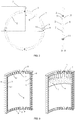
Fig. 1 is an overall schematic view of the present application; -
Fig. 2 is a schematic sectional view of the body of the combined tower according to the present application; -
Fig. 3 is a schematic view of the edge-stiffened combined shell according to the present application, including three-dimensional overall view and detailed view of the interior; -
Fig. 4 is a schematic view of the hollow concrete-filled steel tube structure, for the purpose of instability prevention, according to the present application; and -
Fig. 5 is a schematic view of the connection between the pure steel tower and the combined tower according to the present application;
in which:
1: pure steel tower; 2: combined tower; 3: edge-stiffened combined shell; 4: hollow concrete-filled steel tube structure; 5: outer steel tube; 6: inner steel tube; 7: concrete; 8: external plate; 9: internal plate; 10: stiffening plate; 11: bolt; 12: flange plate; 13: stud; 14: angle steel; and 15: T-shaped steel. - The present application will be further described below with reference to the accompanying drawings.
- As shown in
Fig. 1 , a hybrid wind power tower based on edge-stiffened combined shells is provided. An upper part of the system is apure steel tower 1, while a lower part thereof is a combinedtower 2. The combinedtower 2 is formed by assembling a plurality of edge-stiffened combinedshells 3. - As shown in
Fig. 2 , the combinedtower 2 is formed by assembling 2 to 8 (4, in this figure as an example) edge-stiffened combinedshells 3 in a circumferential direction, and is assembled in segments in a vertical direction. The edge-stiffened combinedshells 3 are prefabricated in a factory and each consist of a hollow concrete-filledsteel tube structure 4, andexternal plates 8,internal plates 9 andstiffening plates 10 arranged around the hollow concrete-filledsteel tube structure 4. Adjacent edge-stiffened combinedshells 3 are connected by thebolts 11. - As shown in
Fig. 3 , theinternal plates 9 are welded on upper, lower, left and right sides of the hollow concrete-filledsteel tube structure 4. The periphery of theouter steel tube 5 is extended outward by a certain distance and then welded with theexternal plates 8, and bolt holes are reserved on theexternal plates 8. A certain number ofstiffening plates 10 are uniformly arranged between theexternal plates 8 and theinternal plates 9 to form a peripheral edge-stiffened region. - As shown in
Fig. 4 , the hollow concrete-filledsteel tube structure 4 consists of anouter steel tube 5, aninner steel tube 6 andconcrete 7, with both the cross section of theouter steel tube 5 and the cross section of theinner steel tube 6 gradually decreasing from the bottom up. On an inner side of theouter steel tube 5 and an outer side of theinner steel tube 6, thestuds 13, theangle steel 14, the T-shaped steel 15 or a combination thereof are welded in advance at certain intervals, and theconcrete 7 is then poured. Theconcrete 7 can be ordinary concrete or lightweight aggregate concrete. - As shown in
Fig. 5 , thepure steel tower 1 in the upper part and the combinedtower 2 in the lower part are connected by theflange plates 12 and thebolts 11. - The present application provides a hybrid wind power tower based on edge-stiffened combined shells. The system gives full play to the advantages of the combined structure, and is reasonable in stress form and reliable in connection. All members can be prefabricated in advance and assembled on site. The system is high in construction efficiency, low in material consumption and convenient to transport, and has a promising prospect in engineering applications.
- The foregoing description merely shows the preferred implementations of the present application, and the present application is not limited to the specific implementations described above. A person of ordinary skill in the art can make various modifications or supplements to the implementations or replace the implementations in a similar way without departing from the principle of the present application, and these modifications, supplements or replacements shall fall into the protection scope of the present application.
- Although the terms (such as, 1: pure steel tower; 2: combined tower; 3: edge-stiffened combined shell; 4: hollow concrete-filled steel tube structure; 5: outer steel tube; 6: inner steel tube; 7: concrete; 8: external plate; 9: internal plate; 10: stiffening plate; 11: bolt; 12: flange plate; 13: stud; 14: angle steel; and, 15: T-shaped steel) have been frequently used herein, other terms are also possible. These terms are merely used for more conveniently describing and explaining the essence of the present application, and the interpretation of these terms into any additional limitations shall be departed from the spirit of the present application.
Claims (4)
- A hybrid wind power tower based on edge-stiffened combined shells, which relates to the technical field of wind power generation, wherein the system comprises a pure steel tower (1), a combined tower (2), edge-stiffened combined shells (3), a hollow concrete-filled steel tube structure (4), outer steel tubes (5), inner steel tubes (6), concrete (7), external plates (8), internal plates (9), stiffening plates (10), bolts (11), flange plates (12), studs (13), angle steel (14) and T-shaped steel (15); an upper part of the system is the pure steel tower (1) while a lower part thereof is the combined tower (2), and the pure steel tower (1) and the combined tower (2) are connected by the flange plates (12) and the bolts (11); and, the combined tower (2) is formed by assembling a plurality of edge-stiffened combined shells (3).
- The hybrid wind power tower based on edge-stiffened combined shells according to claim 1, wherein the combined tower (2) is formed by assembling 2 to 8 edge-stiffened combined shells (3) in a circumferential direction, and is assembled in segments in a vertical direction; the edge-stiffened combined shells (3) are prefabricated in a factory and each consist of a hollow concrete-filled steel tube structure (4), and external plates (8), internal plates (9) and stiffening plates (10) arranged around the hollow concrete-filled steel tube structure (4); and, adjacent edge-stiffened combined shells (3) are connected by the bolts (11).
- The hybrid wind power tower based on edge-stiffened combined shells according to claim 1, wherein the hollow concrete-filled steel tube structure (4) consists of an outer steel tube (5), an inner steel tube (6) and concrete (7), wherein both the cross section of the outer steel tube (5) and the cross section of the inner steel tube (6) gradually decrease from the bottom up; on an inner side of the outer steel tube (5) and on an outer side of the inner steel tube (6), the studs (13), the angle steel (14), the T-shaped steel (15) or a combination thereof are welded in advance at certain intervals, and the concrete (7) is then poured; and, the concrete (7) can be ordinary concrete or lightweight aggregate concrete.
- The hybrid wind power tower based on edge-stiffened combined shells according to claim 1, wherein the internal plates (9) are welded on upper, lower, left and right sides of the hollow concrete-filled steel tube structure (4); the periphery of the outer steel tube (5) is extended outward by a certain distance and then welded with the external plates (8), and bolt holes are reserved on the external plates (8); and, a certain number of stiffening plates (10) are uniformly arranged between the external plates (8) and the internal plates (9) to form a peripheral edge-stiffened region.
Applications Claiming Priority (1)
| Application Number | Priority Date | Filing Date | Title |
|---|---|---|---|
| CN201811504132.2A CN109404224B (en) | 2018-12-10 | 2018-12-10 | A wind turbine hybrid tower based on edge-stiffened composite shell |
Publications (2)
| Publication Number | Publication Date |
|---|---|
| EP3667079A1 true EP3667079A1 (en) | 2020-06-17 |
| EP3667079B1 EP3667079B1 (en) | 2022-02-23 |
Family
ID=65458158
Family Applications (1)
| Application Number | Title | Priority Date | Filing Date |
|---|---|---|---|
| EP19214321.2A Active EP3667079B1 (en) | 2018-12-10 | 2019-12-09 | Hybrid wind power tower based on edge-stiffened combined shells |
Country Status (2)
| Country | Link |
|---|---|
| EP (1) | EP3667079B1 (en) |
| CN (1) | CN109404224B (en) |
Cited By (6)
| Publication number | Priority date | Publication date | Assignee | Title |
|---|---|---|---|---|
| CN112112767A (en) * | 2020-09-15 | 2020-12-22 | 重庆大学 | A combined structure transfer structure for steel-mixed towers of wind turbines |
| CN112922788A (en) * | 2021-03-09 | 2021-06-08 | 中国电建集团西北勘测设计研究院有限公司 | Fan tower section of thick bamboo precast concrete component and fan tower section of thick bamboo |
| CN113719419A (en) * | 2021-10-09 | 2021-11-30 | 重庆大学 | Steel-concrete composite structure switching section of wind generating set |
| JP2022520939A (en) * | 2019-02-13 | 2022-04-04 | ヴォッベン プロパティーズ ゲーエムベーハー | Hybrid tower section, hybrid towers for wind farms and how to make them |
| CN116771187A (en) * | 2023-06-16 | 2023-09-19 | 中铁大桥局集团第四工程有限公司 | An installation method of reinforced steel shell tower |
| WO2024140786A1 (en) * | 2022-12-28 | 2024-07-04 | 深圳国金电力新能设计院有限公司 | Prefabricated tube section of assembled wind turbine tower and assembled wind turbine tower |
Families Citing this family (10)
| Publication number | Priority date | Publication date | Assignee | Title |
|---|---|---|---|---|
| CN111022267A (en) * | 2019-12-27 | 2020-04-17 | 重庆大学 | A hybrid wind power tower based on segmented prestressed multi-cavity composite shell |
| CN111089035A (en) * | 2020-01-17 | 2020-05-01 | 重庆大学 | A prestressed single-layer steel plate-concrete composite tower in a wind turbine unit |
| CN111794914A (en) * | 2020-06-17 | 2020-10-20 | 重庆大学 | A prefabricated hybrid wind power tower based on edge steel plates restraining concrete slabs |
| KR102374486B1 (en) * | 2020-11-17 | 2022-03-16 | 주식회사케이베츠 | Method for contructing offshore substructure using vertical lifting jack and horizontal gripper |
| KR102374485B1 (en) * | 2020-11-17 | 2022-03-16 | 주식회사케이베츠 | Method for contructing offshore substructure using vertical lifting jack and horizontal gripper |
| CN113027692B (en) * | 2021-03-10 | 2022-05-17 | 重庆大学 | Inner ring prestress assembled UHPC tower barrel section for wind power structure |
| CN114043620B (en) * | 2021-12-13 | 2025-06-27 | 中国电力工程顾问集团西北电力设计院有限公司 | An assembled cavity steel-concrete fan tower and manufacturing method thereof |
| CN114962164A (en) * | 2022-07-21 | 2022-08-30 | 西安理工大学 | T-shaped connection built-in stiffening rib concrete filled steel tube bundle fan tower barrel |
| CN116006409B (en) * | 2023-02-21 | 2026-04-14 | 西安建筑科技大学 | Multi-cavity steel plate concrete combined cylinder for welding T-shaped constraint rib plates and construction method |
| CN116591906A (en) * | 2023-05-18 | 2023-08-15 | 华侨大学 | A prefabricated wind power tower, its construction method, and its flexural bearing capacity calculation method |
Citations (3)
| Publication number | Priority date | Publication date | Assignee | Title |
|---|---|---|---|---|
| EP1606514A1 (en) * | 2003-03-19 | 2005-12-21 | Vestas Wind System A/S | Method of constructing large towers for wind turbines |
| KR20180071131A (en) * | 2016-12-19 | 2018-06-27 | 한국해양과학기술원 | Reinforcement-Body for Wind Turbine Tower Structure and Method of Construction for Reinforcing and Heightening |
| CN209398541U (en) * | 2018-12-10 | 2019-09-17 | 重庆大学 | It is a kind of based on edge put more energy into combined shell wind-powered electricity generation mix tower |
Family Cites Families (19)
| Publication number | Priority date | Publication date | Assignee | Title |
|---|---|---|---|---|
| JP4739175B2 (en) * | 2005-12-21 | 2011-08-03 | 日鉄トピーブリッジ株式会社 | Pier structure and pier construction method |
| JP4920623B2 (en) * | 2008-04-02 | 2012-04-18 | 新日本製鐵株式会社 | Concrete filled steel segment |
| CN102269136A (en) * | 2011-08-15 | 2011-12-07 | 上海交通大学 | Tower frame of large wind driven generator |
| CN202359864U (en) * | 2011-12-09 | 2012-08-01 | 黄贺明 | Concrete electric pole assembled by sections and provided with internal connection flanges |
| CN203098165U (en) * | 2013-02-26 | 2013-07-31 | 国电联合动力技术有限公司 | Concrete filled steel tube fan tower |
| EP2806086A1 (en) * | 2013-05-22 | 2014-11-26 | Siemens Aktiengesellschaft | Flange assembly for a tower segment |
| AU2014325437B2 (en) * | 2013-09-25 | 2016-10-13 | Nippon Steel Corporation | Composite structure |
| DE102013016604A1 (en) * | 2013-10-07 | 2015-04-09 | EcoEnterprises GmbH | Steel tube tower of a wind turbine, as well as methods for manufacturing and assembling the tower components |
| JP6229974B2 (en) * | 2014-02-14 | 2017-11-15 | 日本ヒューム株式会社 | Method for forming ring-shaped concrete structural material |
| JP3192516U (en) * | 2014-05-19 | 2014-08-21 | 前田製管株式会社 | Steel pipe concrete composite pile |
| DE202016009246U1 (en) * | 2015-09-15 | 2026-01-28 | Max Bögl Wind AG | Tower for a wind turbine made of ring-segment-shaped precast concrete elements |
| KR101742752B1 (en) * | 2016-03-14 | 2017-06-01 | 한국해양과학기술원 | Hybrid wind power tower combined with steel tower and dsct tower |
| CN106088780B (en) * | 2016-06-29 | 2019-04-19 | 中国航空规划设计研究总院有限公司 | The cast-in-place concrete pylon and its construction method of pre-made void reinforcement bar truss mould plate |
| CN106758786B (en) * | 2016-11-11 | 2018-08-21 | 重庆大学 | A kind of prefabricated assembled concrete-filled double skin steel tube lattice bridge pier |
| CN206467653U (en) * | 2016-12-21 | 2017-09-05 | 浙江大学 | A kind of prefabricated pile attachment means |
| CN206646657U (en) * | 2017-03-25 | 2017-11-17 | 温州瓯林电子科技有限公司 | A kind of high strength steel tube end steel attachment structure |
| CN206784660U (en) * | 2017-05-26 | 2017-12-22 | 中国建筑东北设计研究院有限公司 | Multicarity encased steel plate combined concrete shear wall with T-shaped ribbed stiffener |
| CN107882178A (en) * | 2017-11-23 | 2018-04-06 | 哈尔滨工业大学深圳研究生院 | Assembled Super High steel concrete combines house |
| CN108266330A (en) * | 2018-03-06 | 2018-07-10 | 中国电建集团华东勘测设计研究院有限公司 | A kind of Wind turbines prestressing force steel reinforced concrete tower |
-
2018
- 2018-12-10 CN CN201811504132.2A patent/CN109404224B/en active Active
-
2019
- 2019-12-09 EP EP19214321.2A patent/EP3667079B1/en active Active
Patent Citations (3)
| Publication number | Priority date | Publication date | Assignee | Title |
|---|---|---|---|---|
| EP1606514A1 (en) * | 2003-03-19 | 2005-12-21 | Vestas Wind System A/S | Method of constructing large towers for wind turbines |
| KR20180071131A (en) * | 2016-12-19 | 2018-06-27 | 한국해양과학기술원 | Reinforcement-Body for Wind Turbine Tower Structure and Method of Construction for Reinforcing and Heightening |
| CN209398541U (en) * | 2018-12-10 | 2019-09-17 | 重庆大学 | It is a kind of based on edge put more energy into combined shell wind-powered electricity generation mix tower |
Cited By (6)
| Publication number | Priority date | Publication date | Assignee | Title |
|---|---|---|---|---|
| JP2022520939A (en) * | 2019-02-13 | 2022-04-04 | ヴォッベン プロパティーズ ゲーエムベーハー | Hybrid tower section, hybrid towers for wind farms and how to make them |
| CN112112767A (en) * | 2020-09-15 | 2020-12-22 | 重庆大学 | A combined structure transfer structure for steel-mixed towers of wind turbines |
| CN112922788A (en) * | 2021-03-09 | 2021-06-08 | 中国电建集团西北勘测设计研究院有限公司 | Fan tower section of thick bamboo precast concrete component and fan tower section of thick bamboo |
| CN113719419A (en) * | 2021-10-09 | 2021-11-30 | 重庆大学 | Steel-concrete composite structure switching section of wind generating set |
| WO2024140786A1 (en) * | 2022-12-28 | 2024-07-04 | 深圳国金电力新能设计院有限公司 | Prefabricated tube section of assembled wind turbine tower and assembled wind turbine tower |
| CN116771187A (en) * | 2023-06-16 | 2023-09-19 | 中铁大桥局集团第四工程有限公司 | An installation method of reinforced steel shell tower |
Also Published As
| Publication number | Publication date |
|---|---|
| EP3667079B1 (en) | 2022-02-23 |
| CN109404224A (en) | 2019-03-01 |
| CN109404224B (en) | 2024-06-18 |
Similar Documents
| Publication | Publication Date | Title |
|---|---|---|
| EP3667079B1 (en) | Hybrid wind power tower based on edge-stiffened combined shells | |
| EP2582968B1 (en) | Facility for producing electrical energy from wind | |
| CN102102643A (en) | Lattice hollow-concrete-filled steel tube tower for wind generating set | |
| CN107725281A (en) | Put more energy into a kind of burst assembled T-steel wind energy conversion system steel cylinder tower section | |
| CN109441731A (en) | A kind of wind-powered electricity generation pure steel structure tower having double mechanism of putting more energy into-carry | |
| CN114043620A (en) | Assembled cavity-spliced steel-concrete fan tower cylinder and manufacturing method thereof | |
| CN102182343A (en) | Hollow steel tube concrete tower drum for wind generating set | |
| CN216578490U (en) | Assembled cavity-spliced steel-concrete fan tower cylinder | |
| CN209398541U (en) | It is a kind of based on edge put more energy into combined shell wind-powered electricity generation mix tower | |
| CN215594101U (en) | A truss combined steel mixed cylinder type wind power foundation | |
| CN102536681A (en) | A hexagonal fan tower structure | |
| CN219220629U (en) | Connecting joint structure for vertical wind turbine generator truss and truss adopting same | |
| CN103981887B (en) | A large-scale cylindrical foundation structure suitable for offshore wind power | |
| KR20120073788A (en) | Tower block type wind power generation tower | |
| CN202579061U (en) | Tower drum assembling structure | |
| CN203161451U (en) | Modular wind driven generator tower barrel | |
| CN206206090U (en) | A kind of wind-driven generator tower frame | |
| CN220687492U (en) | Reinforced wind power tower | |
| CN217974457U (en) | A transition section reinforcement structure for the foundation of a large-capacity offshore wind power jacket | |
| CN223434436U (en) | A spliced steel-concrete tower structure | |
| CN207830033U (en) | A kind of SC systems steel plate shear force wall concrete prefabricated wind power generation stepped drum | |
| CN116006409B (en) | Multi-cavity steel plate concrete combined cylinder for welding T-shaped constraint rib plates and construction method | |
| CN222120926U (en) | Wind power mixing tower aluminum mould structure convenient for mould removal | |
| CN218894727U (en) | Split type tower barrel and wind generating set | |
| CN202431462U (en) | A new type of wind power generator tower that is easy to disassemble |
Legal Events
| Date | Code | Title | Description |
|---|---|---|---|
| PUAI | Public reference made under article 153(3) epc to a published international application that has entered the european phase |
Free format text: ORIGINAL CODE: 0009012 |
|
| STAA | Information on the status of an ep patent application or granted ep patent |
Free format text: STATUS: REQUEST FOR EXAMINATION WAS MADE |
|
| 17P | Request for examination filed |
Effective date: 20200319 |
|
| AK | Designated contracting states |
Kind code of ref document: A1 Designated state(s): AL AT BE BG CH CY CZ DE DK EE ES FI FR GB GR HR HU IE IS IT LI LT LU LV MC MK MT NL NO PL PT RO RS SE SI SK SM TR |
|
| AX | Request for extension of the european patent |
Extension state: BA ME |
|
| GRAP | Despatch of communication of intention to grant a patent |
Free format text: ORIGINAL CODE: EPIDOSNIGR1 |
|
| STAA | Information on the status of an ep patent application or granted ep patent |
Free format text: STATUS: GRANT OF PATENT IS INTENDED |
|
| INTG | Intention to grant announced |
Effective date: 20210901 |
|
| GRAJ | Information related to disapproval of communication of intention to grant by the applicant or resumption of examination proceedings by the epo deleted |
Free format text: ORIGINAL CODE: EPIDOSDIGR1 |
|
| STAA | Information on the status of an ep patent application or granted ep patent |
Free format text: STATUS: REQUEST FOR EXAMINATION WAS MADE |
|
| INTC | Intention to grant announced (deleted) | ||
| GRAS | Grant fee paid |
Free format text: ORIGINAL CODE: EPIDOSNIGR3 |
|
| STAA | Information on the status of an ep patent application or granted ep patent |
Free format text: STATUS: GRANT OF PATENT IS INTENDED |
|
| GRAA | (expected) grant |
Free format text: ORIGINAL CODE: 0009210 |
|
| STAA | Information on the status of an ep patent application or granted ep patent |
Free format text: STATUS: THE PATENT HAS BEEN GRANTED |
|
| AK | Designated contracting states |
Kind code of ref document: B1 Designated state(s): AL AT BE BG CH CY CZ DE DK EE ES FI FR GB GR HR HU IE IS IT LI LT LU LV MC MK MT NL NO PL PT RO RS SE SI SK SM TR |
|
| REG | Reference to a national code |
Ref country code: GB Ref legal event code: FG4D |
|
| REG | Reference to a national code |
Ref country code: CH Ref legal event code: EP |
|
| REG | Reference to a national code |
Ref country code: DE Ref legal event code: R096 Ref document number: 602019011843 Country of ref document: DE |
|
| REG | Reference to a national code |
Ref country code: AT Ref legal event code: REF Ref document number: 1470651 Country of ref document: AT Kind code of ref document: T Effective date: 20220315 |
|
| REG | Reference to a national code |
Ref country code: IE Ref legal event code: FG4D |
|
| REG | Reference to a national code |
Ref country code: LT Ref legal event code: MG9D |
|
| REG | Reference to a national code |
Ref country code: NL Ref legal event code: MP Effective date: 20220223 |
|
| REG | Reference to a national code |
Ref country code: AT Ref legal event code: MK05 Ref document number: 1470651 Country of ref document: AT Kind code of ref document: T Effective date: 20220223 |
|
| PG25 | Lapsed in a contracting state [announced via postgrant information from national office to epo] |
Ref country code: SE Free format text: LAPSE BECAUSE OF FAILURE TO SUBMIT A TRANSLATION OF THE DESCRIPTION OR TO PAY THE FEE WITHIN THE PRESCRIBED TIME-LIMIT Effective date: 20220223 Ref country code: RS Free format text: LAPSE BECAUSE OF FAILURE TO SUBMIT A TRANSLATION OF THE DESCRIPTION OR TO PAY THE FEE WITHIN THE PRESCRIBED TIME-LIMIT Effective date: 20220223 Ref country code: PT Free format text: LAPSE BECAUSE OF FAILURE TO SUBMIT A TRANSLATION OF THE DESCRIPTION OR TO PAY THE FEE WITHIN THE PRESCRIBED TIME-LIMIT Effective date: 20220623 Ref country code: NO Free format text: LAPSE BECAUSE OF FAILURE TO SUBMIT A TRANSLATION OF THE DESCRIPTION OR TO PAY THE FEE WITHIN THE PRESCRIBED TIME-LIMIT Effective date: 20220523 Ref country code: NL Free format text: LAPSE BECAUSE OF FAILURE TO SUBMIT A TRANSLATION OF THE DESCRIPTION OR TO PAY THE FEE WITHIN THE PRESCRIBED TIME-LIMIT Effective date: 20220223 Ref country code: LT Free format text: LAPSE BECAUSE OF FAILURE TO SUBMIT A TRANSLATION OF THE DESCRIPTION OR TO PAY THE FEE WITHIN THE PRESCRIBED TIME-LIMIT Effective date: 20220223 Ref country code: HR Free format text: LAPSE BECAUSE OF FAILURE TO SUBMIT A TRANSLATION OF THE DESCRIPTION OR TO PAY THE FEE WITHIN THE PRESCRIBED TIME-LIMIT Effective date: 20220223 Ref country code: ES Free format text: LAPSE BECAUSE OF FAILURE TO SUBMIT A TRANSLATION OF THE DESCRIPTION OR TO PAY THE FEE WITHIN THE PRESCRIBED TIME-LIMIT Effective date: 20220223 Ref country code: BG Free format text: LAPSE BECAUSE OF FAILURE TO SUBMIT A TRANSLATION OF THE DESCRIPTION OR TO PAY THE FEE WITHIN THE PRESCRIBED TIME-LIMIT Effective date: 20220523 |
|
| PG25 | Lapsed in a contracting state [announced via postgrant information from national office to epo] |
Ref country code: PL Free format text: LAPSE BECAUSE OF FAILURE TO SUBMIT A TRANSLATION OF THE DESCRIPTION OR TO PAY THE FEE WITHIN THE PRESCRIBED TIME-LIMIT Effective date: 20220223 Ref country code: LV Free format text: LAPSE BECAUSE OF FAILURE TO SUBMIT A TRANSLATION OF THE DESCRIPTION OR TO PAY THE FEE WITHIN THE PRESCRIBED TIME-LIMIT Effective date: 20220223 Ref country code: GR Free format text: LAPSE BECAUSE OF FAILURE TO SUBMIT A TRANSLATION OF THE DESCRIPTION OR TO PAY THE FEE WITHIN THE PRESCRIBED TIME-LIMIT Effective date: 20220524 Ref country code: FI Free format text: LAPSE BECAUSE OF FAILURE TO SUBMIT A TRANSLATION OF THE DESCRIPTION OR TO PAY THE FEE WITHIN THE PRESCRIBED TIME-LIMIT Effective date: 20220223 Ref country code: AT Free format text: LAPSE BECAUSE OF FAILURE TO SUBMIT A TRANSLATION OF THE DESCRIPTION OR TO PAY THE FEE WITHIN THE PRESCRIBED TIME-LIMIT Effective date: 20220223 |
|
| PG25 | Lapsed in a contracting state [announced via postgrant information from national office to epo] |
Ref country code: IS Free format text: LAPSE BECAUSE OF FAILURE TO SUBMIT A TRANSLATION OF THE DESCRIPTION OR TO PAY THE FEE WITHIN THE PRESCRIBED TIME-LIMIT Effective date: 20220623 |
|
| PG25 | Lapsed in a contracting state [announced via postgrant information from national office to epo] |
Ref country code: SM Free format text: LAPSE BECAUSE OF FAILURE TO SUBMIT A TRANSLATION OF THE DESCRIPTION OR TO PAY THE FEE WITHIN THE PRESCRIBED TIME-LIMIT Effective date: 20220223 Ref country code: SK Free format text: LAPSE BECAUSE OF FAILURE TO SUBMIT A TRANSLATION OF THE DESCRIPTION OR TO PAY THE FEE WITHIN THE PRESCRIBED TIME-LIMIT Effective date: 20220223 Ref country code: RO Free format text: LAPSE BECAUSE OF FAILURE TO SUBMIT A TRANSLATION OF THE DESCRIPTION OR TO PAY THE FEE WITHIN THE PRESCRIBED TIME-LIMIT Effective date: 20220223 Ref country code: EE Free format text: LAPSE BECAUSE OF FAILURE TO SUBMIT A TRANSLATION OF THE DESCRIPTION OR TO PAY THE FEE WITHIN THE PRESCRIBED TIME-LIMIT Effective date: 20220223 Ref country code: DK Free format text: LAPSE BECAUSE OF FAILURE TO SUBMIT A TRANSLATION OF THE DESCRIPTION OR TO PAY THE FEE WITHIN THE PRESCRIBED TIME-LIMIT Effective date: 20220223 Ref country code: CZ Free format text: LAPSE BECAUSE OF FAILURE TO SUBMIT A TRANSLATION OF THE DESCRIPTION OR TO PAY THE FEE WITHIN THE PRESCRIBED TIME-LIMIT Effective date: 20220223 |
|
| REG | Reference to a national code |
Ref country code: DE Ref legal event code: R097 Ref document number: 602019011843 Country of ref document: DE |
|
| PG25 | Lapsed in a contracting state [announced via postgrant information from national office to epo] |
Ref country code: AL Free format text: LAPSE BECAUSE OF FAILURE TO SUBMIT A TRANSLATION OF THE DESCRIPTION OR TO PAY THE FEE WITHIN THE PRESCRIBED TIME-LIMIT Effective date: 20220223 |
|
| PLBE | No opposition filed within time limit |
Free format text: ORIGINAL CODE: 0009261 |
|
| STAA | Information on the status of an ep patent application or granted ep patent |
Free format text: STATUS: NO OPPOSITION FILED WITHIN TIME LIMIT |
|
| 26N | No opposition filed |
Effective date: 20221124 |
|
| PG25 | Lapsed in a contracting state [announced via postgrant information from national office to epo] |
Ref country code: SI Free format text: LAPSE BECAUSE OF FAILURE TO SUBMIT A TRANSLATION OF THE DESCRIPTION OR TO PAY THE FEE WITHIN THE PRESCRIBED TIME-LIMIT Effective date: 20220223 |
|
| REG | Reference to a national code |
Ref country code: DE Ref legal event code: R119 Ref document number: 602019011843 Country of ref document: DE |
|
| PG25 | Lapsed in a contracting state [announced via postgrant information from national office to epo] |
Ref country code: IT Free format text: LAPSE BECAUSE OF FAILURE TO SUBMIT A TRANSLATION OF THE DESCRIPTION OR TO PAY THE FEE WITHIN THE PRESCRIBED TIME-LIMIT Effective date: 20220223 |
|
| REG | Reference to a national code |
Ref country code: CH Ref legal event code: PL |
|
| REG | Reference to a national code |
Ref country code: BE Ref legal event code: MM Effective date: 20221231 |
|
| PG25 | Lapsed in a contracting state [announced via postgrant information from national office to epo] |
Ref country code: LU Free format text: LAPSE BECAUSE OF NON-PAYMENT OF DUE FEES Effective date: 20221209 |
|
| PG25 | Lapsed in a contracting state [announced via postgrant information from national office to epo] |
Ref country code: LI Free format text: LAPSE BECAUSE OF NON-PAYMENT OF DUE FEES Effective date: 20221231 Ref country code: IE Free format text: LAPSE BECAUSE OF NON-PAYMENT OF DUE FEES Effective date: 20221209 Ref country code: DE Free format text: LAPSE BECAUSE OF NON-PAYMENT OF DUE FEES Effective date: 20230701 Ref country code: CH Free format text: LAPSE BECAUSE OF NON-PAYMENT OF DUE FEES Effective date: 20221231 |
|
| PG25 | Lapsed in a contracting state [announced via postgrant information from national office to epo] |
Ref country code: FR Free format text: LAPSE BECAUSE OF NON-PAYMENT OF DUE FEES Effective date: 20221231 Ref country code: BE Free format text: LAPSE BECAUSE OF NON-PAYMENT OF DUE FEES Effective date: 20221231 |
|
| PG25 | Lapsed in a contracting state [announced via postgrant information from national office to epo] |
Ref country code: HU Free format text: LAPSE BECAUSE OF FAILURE TO SUBMIT A TRANSLATION OF THE DESCRIPTION OR TO PAY THE FEE WITHIN THE PRESCRIBED TIME-LIMIT; INVALID AB INITIO Effective date: 20191209 |
|
| PG25 | Lapsed in a contracting state [announced via postgrant information from national office to epo] |
Ref country code: CY Free format text: LAPSE BECAUSE OF FAILURE TO SUBMIT A TRANSLATION OF THE DESCRIPTION OR TO PAY THE FEE WITHIN THE PRESCRIBED TIME-LIMIT Effective date: 20220223 |
|
| PG25 | Lapsed in a contracting state [announced via postgrant information from national office to epo] |
Ref country code: MK Free format text: LAPSE BECAUSE OF FAILURE TO SUBMIT A TRANSLATION OF THE DESCRIPTION OR TO PAY THE FEE WITHIN THE PRESCRIBED TIME-LIMIT Effective date: 20220223 |
|
| PG25 | Lapsed in a contracting state [announced via postgrant information from national office to epo] |
Ref country code: MC Free format text: LAPSE BECAUSE OF FAILURE TO SUBMIT A TRANSLATION OF THE DESCRIPTION OR TO PAY THE FEE WITHIN THE PRESCRIBED TIME-LIMIT Effective date: 20220223 |
|
| PG25 | Lapsed in a contracting state [announced via postgrant information from national office to epo] |
Ref country code: MC Free format text: LAPSE BECAUSE OF FAILURE TO SUBMIT A TRANSLATION OF THE DESCRIPTION OR TO PAY THE FEE WITHIN THE PRESCRIBED TIME-LIMIT Effective date: 20220223 |
|
| PG25 | Lapsed in a contracting state [announced via postgrant information from national office to epo] |
Ref country code: MT Free format text: LAPSE BECAUSE OF FAILURE TO SUBMIT A TRANSLATION OF THE DESCRIPTION OR TO PAY THE FEE WITHIN THE PRESCRIBED TIME-LIMIT Effective date: 20220223 |
|
| PG25 | Lapsed in a contracting state [announced via postgrant information from national office to epo] |
Ref country code: TR Free format text: LAPSE BECAUSE OF FAILURE TO SUBMIT A TRANSLATION OF THE DESCRIPTION OR TO PAY THE FEE WITHIN THE PRESCRIBED TIME-LIMIT Effective date: 20220223 |
|
| PGFP | Annual fee paid to national office [announced via postgrant information from national office to epo] |
Ref country code: GB Payment date: 20251229 Year of fee payment: 7 |