EP3667100B1 - Turbocompresseur doté d'un mécanisme de garniture réglable et d'un atténuateur de bruit - Google Patents
Turbocompresseur doté d'un mécanisme de garniture réglable et d'un atténuateur de bruit Download PDFInfo
- Publication number
- EP3667100B1 EP3667100B1 EP19207598.4A EP19207598A EP3667100B1 EP 3667100 B1 EP3667100 B1 EP 3667100B1 EP 19207598 A EP19207598 A EP 19207598A EP 3667100 B1 EP3667100 B1 EP 3667100B1
- Authority
- EP
- European Patent Office
- Prior art keywords
- blades
- inlet
- air inlet
- compressor
- plate
- Prior art date
- Legal status (The legal status is an assumption and is not a legal conclusion. Google has not performed a legal analysis and makes no representation as to the accuracy of the status listed.)
- Active
Links
Images



Classifications
-
- F—MECHANICAL ENGINEERING; LIGHTING; HEATING; WEAPONS; BLASTING
- F02—COMBUSTION ENGINES; HOT-GAS OR COMBUSTION-PRODUCT ENGINE PLANTS
- F02B—INTERNAL-COMBUSTION PISTON ENGINES; COMBUSTION ENGINES IN GENERAL
- F02B37/00—Engines characterised by provision of pumps driven at least for part of the time by exhaust
- F02B37/12—Control of the pumps
- F02B37/24—Control of the pumps by using pumps or turbines with adjustable guide vanes
-
- F—MECHANICAL ENGINEERING; LIGHTING; HEATING; WEAPONS; BLASTING
- F04—POSITIVE - DISPLACEMENT MACHINES FOR LIQUIDS; PUMPS FOR LIQUIDS OR ELASTIC FLUIDS
- F04D—NON-POSITIVE-DISPLACEMENT PUMPS
- F04D29/00—Details, component parts, or accessories
- F04D29/40—Casings; Connections of working fluid
- F04D29/42—Casings; Connections of working fluid for radial or helico-centrifugal pumps
- F04D29/44—Fluid-guiding means, e.g. diffusers
- F04D29/46—Fluid-guiding means, e.g. diffusers adjustable
- F04D29/462—Fluid-guiding means, e.g. diffusers adjustable especially adapted for elastic fluid pumps
- F04D29/464—Fluid-guiding means, e.g. diffusers adjustable especially adapted for elastic fluid pumps adjusting flow cross-section, otherwise than by using adjustable stator blades
-
- F—MECHANICAL ENGINEERING; LIGHTING; HEATING; WEAPONS; BLASTING
- F04—POSITIVE - DISPLACEMENT MACHINES FOR LIQUIDS; PUMPS FOR LIQUIDS OR ELASTIC FLUIDS
- F04D—NON-POSITIVE-DISPLACEMENT PUMPS
- F04D29/00—Details, component parts, or accessories
- F04D29/40—Casings; Connections of working fluid
- F04D29/42—Casings; Connections of working fluid for radial or helico-centrifugal pumps
- F04D29/4206—Casings; Connections of working fluid for radial or helico-centrifugal pumps especially adapted for elastic fluid pumps
- F04D29/4213—Casings; Connections of working fluid for radial or helico-centrifugal pumps especially adapted for elastic fluid pumps suction ports
-
- F—MECHANICAL ENGINEERING; LIGHTING; HEATING; WEAPONS; BLASTING
- F01—MACHINES OR ENGINES IN GENERAL; ENGINE PLANTS IN GENERAL; STEAM ENGINES
- F01D—NON-POSITIVE DISPLACEMENT MACHINES OR ENGINES, e.g. STEAM TURBINES
- F01D17/00—Regulating or controlling by varying flow
- F01D17/10—Final actuators
- F01D17/12—Final actuators arranged in stator parts
- F01D17/14—Final actuators arranged in stator parts varying effective cross-sectional area of nozzles or guide conduits
- F01D17/141—Final actuators arranged in stator parts varying effective cross-sectional area of nozzles or guide conduits by means of shiftable members or valves obturating part of the flow path
-
- F—MECHANICAL ENGINEERING; LIGHTING; HEATING; WEAPONS; BLASTING
- F01—MACHINES OR ENGINES IN GENERAL; ENGINE PLANTS IN GENERAL; STEAM ENGINES
- F01D—NON-POSITIVE DISPLACEMENT MACHINES OR ENGINES, e.g. STEAM TURBINES
- F01D17/00—Regulating or controlling by varying flow
- F01D17/10—Final actuators
- F01D17/12—Final actuators arranged in stator parts
- F01D17/14—Final actuators arranged in stator parts varying effective cross-sectional area of nozzles or guide conduits
- F01D17/16—Final actuators arranged in stator parts varying effective cross-sectional area of nozzles or guide conduits by means of nozzle vanes
- F01D17/167—Final actuators arranged in stator parts varying effective cross-sectional area of nozzles or guide conduits by means of nozzle vanes of vanes moving in translation
-
- F—MECHANICAL ENGINEERING; LIGHTING; HEATING; WEAPONS; BLASTING
- F02—COMBUSTION ENGINES; HOT-GAS OR COMBUSTION-PRODUCT ENGINE PLANTS
- F02B—INTERNAL-COMBUSTION PISTON ENGINES; COMBUSTION ENGINES IN GENERAL
- F02B37/00—Engines characterised by provision of pumps driven at least for part of the time by exhaust
-
- F—MECHANICAL ENGINEERING; LIGHTING; HEATING; WEAPONS; BLASTING
- F04—POSITIVE - DISPLACEMENT MACHINES FOR LIQUIDS; PUMPS FOR LIQUIDS OR ELASTIC FLUIDS
- F04D—NON-POSITIVE-DISPLACEMENT PUMPS
- F04D29/00—Details, component parts, or accessories
- F04D29/40—Casings; Connections of working fluid
- F04D29/42—Casings; Connections of working fluid for radial or helico-centrifugal pumps
- F04D29/44—Fluid-guiding means, e.g. diffusers
- F04D29/441—Fluid-guiding means, e.g. diffusers especially adapted for elastic fluid pumps
- F04D29/444—Bladed diffusers
-
- F—MECHANICAL ENGINEERING; LIGHTING; HEATING; WEAPONS; BLASTING
- F04—POSITIVE - DISPLACEMENT MACHINES FOR LIQUIDS; PUMPS FOR LIQUIDS OR ELASTIC FLUIDS
- F04D—NON-POSITIVE-DISPLACEMENT PUMPS
- F04D29/00—Details, component parts, or accessories
- F04D29/66—Combating cavitation, whirls, noise, vibration or the like; Balancing
- F04D29/661—Combating cavitation, whirls, noise, vibration or the like; Balancing especially adapted for elastic fluid pumps
- F04D29/663—Sound attenuation
- F04D29/665—Sound attenuation by means of resonance chambers or interference
-
- F—MECHANICAL ENGINEERING; LIGHTING; HEATING; WEAPONS; BLASTING
- F05—INDEXING SCHEMES RELATING TO ENGINES OR PUMPS IN VARIOUS SUBCLASSES OF CLASSES F01-F04
- F05D—INDEXING SCHEME FOR ASPECTS RELATING TO NON-POSITIVE-DISPLACEMENT MACHINES OR ENGINES, GAS-TURBINES OR JET-PROPULSION PLANTS
- F05D2220/00—Application
- F05D2220/40—Application in turbochargers
-
- F—MECHANICAL ENGINEERING; LIGHTING; HEATING; WEAPONS; BLASTING
- F05—INDEXING SCHEMES RELATING TO ENGINES OR PUMPS IN VARIOUS SUBCLASSES OF CLASSES F01-F04
- F05D—INDEXING SCHEME FOR ASPECTS RELATING TO NON-POSITIVE-DISPLACEMENT MACHINES OR ENGINES, GAS-TURBINES OR JET-PROPULSION PLANTS
- F05D2250/00—Geometry
- F05D2250/50—Inlet or outlet
- F05D2250/51—Inlet
Definitions
- the present disclosure relates to compressors, such as used in turbochargers, and more particularly relates to compressors in which the effective inlet area or diameter can be adjusted for different operating conditions.
- An exhaust gas-driven turbocharger is a device used in conjunction with an internal combustion engine for increasing the power output of the engine by compressing the air that is delivered to the air intake of the engine to be mixed with fuel and burned in the engine.
- a turbocharger comprises a compressor wheel mounted on one end of a shaft in a compressor housing and a turbine wheel mounted on the other end of the shaft in a turbine housing.
- the turbine housing is formed separately from the compressor housing, and there is yet another center housing connected between the turbine and compressor housings for containing bearings for the shaft.
- the turbine housing defines a generally annular chamber that surrounds the turbine wheel and that receives exhaust gas from an engine.
- the turbine assembly includes a nozzle that leads from the chamber into the turbine wheel.
- the exhaust gas flows from the chamber through the nozzle to the turbine wheel and the turbine wheel is driven by the exhaust gas.
- the turbine thus extracts power from the exhaust gas and drives the compressor.
- the compressor receives ambient air through an inlet of the compressor housing and the air is compressed by the compressor wheel and is then discharged from the housing to the engine air intake.
- Turbochargers typically employ a compressor wheel of the centrifugal (also known as "radial") type because centrifugal compressors can achieve relatively high pressure ratios in a compact arrangement.
- Intake air for the compressor is received in a generally axial direction at an inducer portion of the centrifugal compressor wheel and is discharged in a generally radial direction at an exducer portion of the wheel.
- the compressed air from the wheel is delivered to a volute, and from the volute the air is supplied to the intake of an internal combustion engine.
- the operating range of the compressor is an important aspect of the overall performance of the turbocharger.
- the operating range is generally delimited by a surge line and a choke line on an operating map for the compressor.
- the compressor map is typically presented as pressure ratio (discharge pressure Pout divided by inlet pressure Pin ) on the vertical axis, versus corrected mass flow rate on the horizontal axis.
- the choke line on the compressor map is located at high flow rates and represents the locus of maximum mass-flow-rate points over a range of pressure ratios; that is, for a given point on the choke line, it is not possible to increase the flow rate while maintaining the same pressure ratio because a choked-flow condition occurs in the compressor.
- the surge line is located at low flow rates and represents the locus of minimum mass-flow-rate points without surge, over a range of pressure ratios; that is, for a given point on the surge line, reducing the flow rate without changing the pressure ratio, or increasing the pressure ratio without changing the flow rate, would lead to surge occurring.
- Surge is a flow instability that typically occurs when the compressor blade incidence angles become so large that substantial flow separation arises on the compressor blades. Pressure fluctuation and flow reversal can happen during surge.
- compressor surge may occur when the engine is operating at high load or torque and low engine speed, or when the engine is operating at a low speed and there is a high level of exhaust gas recirculation (EGR). Surge can also arise when an engine is suddenly decelerated from a high-speed condition. Expanding the surge-free operation range of a compressor to lower flow rates is a goal often sought in compressor design.
- EGR exhaust gas recirculation
- Applicant is the owner of several patent applications describing various inlet-adjustment mechanisms for delaying the onset of surge to lower flow rates at a given compressor pressure ratio (i.e., shifting the surge line to the left on the compressor map), including but not limited to: Application No. 14/642,825 filed on Mar. 10, 2015 ; 14/551,218 filed on Nov. 24, 2014 ; 14/615,428 filed on Feb. 6, 2016 ; 15/446,054 filed on Mar. 1, 2017 ; 15/446,090 filed on Mar. 1, 2017 ; 15/456,403 filed on Mar. 10, 2017 ; 15/836,781 filed on Dec. 8, 2017 ; 15/806,267 filed on Nov. 7, 2017 ; 15/822,093 filed on Nov.
- Inlet-adjustment mechanisms in accordance with said application; and for example US2017/0298953 A1 generally include a plurality of blades or vanes that collectively circumscribe an orifice whose effective diameter is adjustable by movement of the blades or vanes radially inwardly or outwardly.
- the present application relates to turbochargers whose compressor includes an inlet-adjustment mechanism of the type noted above. Applicant has discovered that when the inlet-adjustment mechanism is closed to effectively reduce the diameter of the compressor inlet, the mechanism can generate aerodynamically induced noise at certain frequencies. It is an aim of the present application to address this issue and mitigate such noise.
- a turbocharger comprises a turbine including a turbine housing, and a compressor assembly comprising a compressor housing and a compressor wheel mounted in the compressor housing and connected to a rotatable shaft for rotation therewith.
- the compressor wheel has blades and defines an inducer portion, the compressor housing having an air inlet wall defining an air inlet for leading air generally axially into the compressor wheel, the air inlet wall defining an annular space therein upstream of the compressor wheel, a radially innermost extremity of the annular space being open to the air inlet.
- An inlet-adjustment mechanism is disposed in the air inlet and is adjustable between an open position and a closed position.
- the inlet-adjustment mechanism comprises a plurality of blades disposed about the air inlet and collectively circumscribing an orifice, the blades being movable radially inwardly into the air inlet when the blades are in the closed position so as to cause the orifice to have a reduced diameter relative to a nominal diameter of the inlet.
- the turbocharger further comprises a noise-attenuator disposed in the annular space downstream of the inlet-adjustment mechanism, the noise-attenuator being structured and arranged to define axially consecutive first and second annular cavities each of which is open to the air inlet.
- the first annular cavity has a radial height h1 and the second annular cavity has a radial height h2.
- h1 and h2 are not equal.
- the first annular cavity is upstream of the second annular cavity, and h1 is greater than h2.
- the noise-attenuator comprises a ring-shaped first plate and a ring-shaped second plate axially abutting the first plate.
- the first plate defines a flange at a radially outer periphery thereof, the flange projecting axially upstream from an upstream face of the first plate.
- the inlet-adjustment mechanism includes a rotatable unison ring for actuating movement of the blades, and the unison ring abuts the flange of the first plate, the flange forming a bearing surface for the unison ring when the unison ring is rotated.
- the blades of the inlet-adjustment mechanism can be mounted to the first plate by pivot pins, the blades engaging the unison ring such that rotation of the unison ring in one direction or an opposite direction causes the blades to pivot radially inwardly or radially outwardly for adjusting a size of the orifice.
- the noise-attenuator cooperates with the annular space in the air inlet wall to define an annular cavity
- the noise-attenuator comprises a plurality of elongate fingers that bridge across from an upstream side to a downstream side of the annular cavity, adjacent a radially inner end thereof.
- the fingers are non-uniformly circumferentially spaced about an entire circumference of the air inlet.
- the noise-attenuator comprises a ring-shaped plate, the fingers projecting axially downstream from a downstream face of the plate adjacent a radially inner periphery thereof.
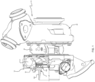
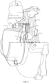
- a turbocharger 10 in accordance with one embodiment of the invention is illustrated in side view in FIG. 1 , and an axial cross-sectional view of the turbocharger is shown in FIG. 2 .
- the turbocharger includes a compressor 12 and a turbine 22.
- the compressor comprises a compressor wheel or impeller 14 mounted in a compressor housing 16 on one end of a rotatable shaft 18.
- the compressor housing includes an air inlet wall 17 that defines an air inlet for leading air generally axially into the compressor wheel 14.
- the shaft is supported in bearings mounted in a center housing 20 of the turbocharger. The shaft is rotated by a turbine wheel (not visible in FIG. 1 ) of the turbine 22.
- the turbine wheel is mounted on the other end of the shaft 18 from the compressor wheel, thereby rotatably driving the compressor wheel, which compresses air drawn in through the compressor inlet and discharges the compressed air generally radially outwardly from the compressor wheel into a volute 21 for receiving the compressed air. From the volute 21, the air is routed to the intake of an internal combustion engine (not shown) for boosting the performance of the engine.
- the turbine wheel is disposed within a turbine housing 24 that defines an annular chamber for receiving exhaust gases from an internal combustion engine (not shown).
- the turbine housing also defines a nozzle for directing exhaust gases from the chamber generally radially inwardly to the turbine wheel.
- the exhaust gases are expanded as they pass through the turbine wheel, and rotatably drive the turbine wheel, which in turn rotatably drives the compressor wheel 14 as already noted.
- the air inlet wall 17 is formed in part by the compressor housing 16 and in part by a separate inlet duct member 16d that is received into a cylindrical receptacle defined by the compressor housing.
- the portion of the air inlet wall 17 proximate the compressor wheel 14 defines a generally cylindrical inner surface that has a diameter generally matched to the diameter of an inducer portion 14i of the compressor wheel.
- the compressor housing 16 defines a shroud surface 16s that is closely adjacent to the radially outer tips of the compressor blades.
- the shroud surface defines a curved contour that is generally parallel to the contour of the compressor wheel.
- the compressor of the turbocharger includes an inlet-adjustment mechanism 100 disposed in an annular space S within the air inlet wall 17.
- the annular space S is defined between a downstream-facing end surface ES of the inlet duct member 16d, an upstream-facing surface 30 of the compressor housing 16, and a cylindrical radially inwardly facing surface 32 of the compressor housing.
- the inlet-adjustment mechanism comprises a ring-shaped assembly and is operable for adjusting an effective diameter of the air inlet into the compressor wheel.
- the inlet-adjustment mechanism is movable between an open position and a closed position, and in some embodiments can be closed still further to a super-closed position, and can be configured to be adjusted to various points intermediate between said positions.
- the inlet-adjustment mechanism comprises a plurality of blades 102 arranged about the central axis of the air inlet and each pivotable about a pivot pin located at or near one end of the blade.
- the mechanism further comprises a unison ring 106 that is rotatable about the central axis and is engaged with each of the blades 102 such that rotation of the unison ring in one direction causes the blades to pivot radially inwardly and rotation in the opposite direction causes the blades to pivot radially outwardly.
- the inlet-adjustment mechanism can comprise other types of blade or vane arrangements that actuate the blades or vanes to move inwardly or outwardly in a different fashion, e.g., translating radially, or moving with a combined radial and circumferential motion (i.e., helical motion).
- the range of pivotal movement of the blades 102 is sufficient that the blades can be pivoted radially outwardly by rotation of the unison ring in one direction to an open position, in which the blades are entirely radially outward of the inner surface of the air inlet wall 17.
- the inlet-adjustment mechanism does not alter the nominal inlet diameter as defined by the inlet surface.
- the blades can also be pivoted radially inwardly by rotation of the unison ring in the opposite direction to a closed position.
- the circular-arc edges along the radially inner sides of the blades 102 collectively form an orifice that is substantially a circle having a diameter that is less than that of the inlet inner surface. This has the consequence that the effective diameter of the inlet is reduced relative to the nominal inlet diameter. In this manner, the inlet-adjustment mechanism is able to regulate the effective diameter of the air inlet approaching the compressor wheel.
- the inlet-adjustment mechanism 100 can be placed in the closed position. This can have the effect of reducing the effective inlet diameter and thus of increasing the flow velocity into the compressor wheel. The result will be a reduction in compressor blade incidence angles, effectively stabilizing the flow (i.e., making blade stall and compressor surge less likely). In other words, the surge line of the compressor will be moved to lower flow rates (to the left on a map of compressor pressure ratio versus flow rate).
- the inlet-adjustment mechanism 100 can be partially opened or fully opened. This can have the effect of increasing the effective inlet diameter so that the compressor regains its high-flow performance and choke flow essentially as if the inlet-adjustment mechanism were not present and as if the compressor had a conventional inlet matched to the wheel diameter at the inducer portion of the wheel.
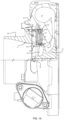
- noise attenuation is accomplished by providing a noise-attenuator 120 located just downstream of the inlet-adjustment mechanism 100, as best seen in FIGS. 1A , 4A, and 4B .
- the noise-attenuator 120 is disposed within the annular space S of the air inlet wall 17. As shows in FIG.
- the inlet-adjustment mechanism 100 is also disposed within the annular space S , immediately adjacent to the end surface ES of the inlet duct member 16d.
- the noise-attenuator 120 is disposed downstream of the inlet-adjustment mechanism, and comprises a ring-shaped first plate P1 and a ring-shaped second plate P2 that are consecutively axially disposed, such that the first plate P1 confronts the inlet-adjustment mechanism 100, and the second plate P2 is immediately downstream of the first plate.
- the noise-attenuator is structured and arranged to define at least two axially consecutive annular cavities each of which is open to the air inlet.
- the noise-attenuator defines two such axially consecutive annular cavities C1 and C2.
- a further annular cavity C3 is defined by the abutment of a first flange F1 from a radially outer periphery of the first plate P1 with the unison ring 106 of the inlet-adjustment mechanism, but this cavity C3 is unrelated to noise attenuation, being instead the space in which the inlet-adjustment mechanism 100 resides.
- the first flange extends in the upstream direction from the first plate to abut the unison ring, thereby spacing the unison ring axially away from the upstream face of the first plate P1.
- the blades 102 of the inlet-adjustment mechanism are pivotally mounted (as further described below) to the first plate P1 and at least partially reside within the third annular cavity C3.
- the first annular cavity C1 is defined by the abutment of a second flange F2 from the second plate P2 with a downstream side of the first plate P1, the second flange F2 projecting in the upstream direction from a radially outer periphery of the second plate.
- the second annular cavity has a radial height h1 . It will be appreciated that the first cavity could be created by a second flange projecting downstream from the first plate P1 and abutting the second plate P2 (which then would not have a flange at its upstream side).
- the invention is not limited to any particular structures or arrangements for creating the cavities.
- a second annular cavity C2 is defined by the abutment of a third flange F3, which projects in the downstream direction from a radially outer periphery of the second plate P2, with the downstream wall 30 of the annular space S defined in the air inlet wall 17.
- the second annular cavity has a radial height h2. The values of h1 and h2 differ from each other.
- the first annular cavity C1 has an axial width of tC1
- the second annular cavity C2 has an axial width of tC2.
- the second plate P2 has an axial thickness of tP2.
- the values of tC1 and tC2 are not equal to the plate thickness tP2.
- the cavity widths tC1 and tC2 can be equal to each other and can be greater than the second plate thickness tP2.
- the blades 102 of the inlet-adjustment mechanism are pivotally mounted to the first plate P1.
- the pins 113 pass through corresponding holes 124 in the second plate P2 and through corresponding holes 123 in the first plate P1, and are received in bearing holes 103 in each of the blades 102, as best seen in FIG. 2 .
- the blades 102 thus are pivotable about the pins 113.
- Ends of the blades are received into slots 107 in the inner periphery of the unison ring 106, and hence rotation of the unison ring about the turbocharger axis causes the blades to pivot as noted.
- Rotation of the unison ring is guided by a plurality of guide pins 111 that are fixedly mounted in holes (not shown) in the downstream wall 30.
- the guide pins pass through corresponding holes 122 in the second plate P2 and through corresponding holes 121 in the first plate P1 and engage with the inner periphery of the unison ring 106 to guide its rotational motion and keep it substantially concentric with the turbocharger axis.
- the two annular cavities C1 and C2 act as quarter-wave resonators for the main fluid flow passing through the air inlet toward the compressor wheel.
- a quarter-wave resonator can be tuned to a certain fundamental frequency, so that it attenuates that frequency and harmonics of that frequency, based on the length (which in this case is the radial height h1 or h2 ) of the cavity.
- the two cavities C1 and C2 can be tuned to the same frequency by making their radial heights equal, or can be tuned to different frequencies by making their radial heights different from each other.
- the plate P2 between the two cavities serves as a partition wall that helps reduce the energy of vortices generated from the blades of the inlet-adjustment mechanism 100, and hence helps reduce the noise associated with such vortical flow. While the illustrated embodiment has two such annular cavities acting as quarter-wave resonators, the invention is not limited in that respect, and more than two such cavities can be employed if advantageous in a particular case.
- the noise-attenuator 220 comprises a ring-shaped plate having a flange F that extends in the upstream direction from a radially outer periphery of the plate and abuts the unison ring 106, similar to the first plate of the the noise-attenuator 120.
- the blades 102 of the inlet-adjustment mechanism are pivotally mounted to the noise-attenuator 220 by pins 113 that pass through holes 223 in the plate and are fixedly mounted in holes in the downstream wall 30 of the annular space in the air inlet wall, also similar to the the noise-attenuator 120.
- Guide pins 111 for the unison ring 106 extend through holes 221 in the plate and are mounted in holes in the wall 30 (see particularly, FIG. 5 ).
- this noise-attenuator includes a plurality of fingers 222 that extend in the downstream direction from a radially inner periphery of the noise-attenuator.
- the noise-attenuator 220 cooperates with the annular space S to define an annular cavity C .
- the fingers 222 bridge across the cavity C and are non-uniformly circumferentially spaced about an entire circumference of the air inlet.
- Each of the fingers 222 causes a sudden change in impedance to the air approaching the compressor wheel, and because the fingers are non-uniformly spaced, the impedance continuously varies about the circumference, which helps prevent transmission of noise.
Landscapes
- Engineering & Computer Science (AREA)
- Mechanical Engineering (AREA)
- General Engineering & Computer Science (AREA)
- Chemical & Material Sciences (AREA)
- Combustion & Propulsion (AREA)
- Supercharger (AREA)
- Structures Of Non-Positive Displacement Pumps (AREA)
Claims (11)
- Turbocompresseur, comprenant :une turbine (22) incluant un logement de turbine ;un montage de compresseur comprenant un logement de compresseur (16) et une roue de compresseur (14) montée dans le logement de compresseur et reliée à un arbre rotatif (18) pour tourner avec celui-ci, la roue de compresseur ayant des aubes et définissant une partie d'inducteur, le logement de compresseur ayant une paroi d'entrée d'air (17) définissant une entrée d'air pour guider l'air généralement axialement jusque dans la roue de compresseur, la paroi d'entrée d'air définissant un espace annulaire (S) à l'intérieur en amont de la roue de compresseur, une extrémité la plus radialement à l'intérieur de l'espace annulaire étant ouverte vers l'entrée d'air, un mécanisme d'ajustement d'entrée (100) disposé dans l'espace annulaire et ajustable entre une position ouverte et une position fermée, le mécanisme d'ajustement d'entrée comprenant une pluralité d'aubes (102) disposées autour de l'entrée d'air et entourant collectivement un orifice, les aubes étant mobiles radialement vers l'intérieur jusque dans l'entrée d'air lorsque les aubes sont dans la position fermée de manière à faire que l'orifice ait un diamètre réduit par rapport à un diamètre nominal de l'entrée ;caractérisé en ce qu'un atténuateur de bruit est disposé dans l'espace annulaire en aval du mécanique d'ajustement d'entrée, l'atténuateur de bruit étant structuré et agencé pour définir des première (C1) et secondes (C2) cavités annulaires consécutives axialement, dont chacune est ouverte vers l'entrée d'air de façon à ce que chacune des première et seconde cavités annulaires agisse en tant qu'un résonateur quart d'onde, la première cavité annulaire ayant une hauteur radiale hl et la seconde cavité annulaire ayant une hauteur radiale h2, dans lequel h1 et h2 ne sont pas égaux.
- Turbocompresseur selon la revendication 1, dans lequel l'atténuateur de bruit comprend une première plaque (P1) de forme annulaire et une seconde plaque (P2) de forme annulaire axialement adjacente à la première plaque.
- Turbocompresseur selon la revendication 2, dans lequel chacune de la première (C1) et de la secondes (C2) cavités annulaires présente une largeur axiale qui est supérieure à une épaisseur axiale de la seconde plaque.
- Turbocompresseur selon la revendication 2, dans lequel la première plaque (P1) définit une bride (F1) à une périphérie radialement extérieure de celle-ci, la bride faisant saillie axialement en amont d'une face en amont de la première plaque.
- Turbocompresseur selon la revendication 4, dans lequel le mécanisme d'ajustement d'entrée inclut un anneau de conjugaison (106) rotatif pour déclencher le mouvement des aubes, l'anneau de conjugaison étant adjacent à la bride, la bride formant une surface de palier pour l'anneau de conjugaison lorsque l'anneau de conjugaison est tourné.
- Turbocompresseur selon la revendication 5, dans lequel les aubes sont montées pivotantes sur la première plaque (P1), les aubes engageant l'anneau de conjugaison de façon à ce que la rotation de l'anneau de conjugaison dans une direction ou une direction opposée fasse que les aubes pivotent radialement vers l'intérieur ou radialement vers l'extérieur pour ajuster une taille de l'orifice.
- Turbocompresseur, comprenant :une turbine (22) incluant un logement de turbine ;un montage de compresseur comprenant un logement de compresseur (16) et une roue de compresseur (14) montée dans le logement de compresseur et reliée à un arbre rotatif (18) pour tourner avec celui-ci, la roue de compresseur ayant des aubes et définissant une partie d'inducteur, le logement de compresseur ayant une paroi d'entrée d'air (17) définissant une entrée d'air pour guider l'air généralement axialement jusque dans la roue de compresseur, la paroi d'entrée d'air définissant un espace annulaire (S) à l'intérieur en amont de la roue de compresseur, une extrémité la plus radialement à l'intérieur de l'espace annulaire étant ouverte vers l'entrée d'air, un mécanisme d'ajustement d'entrée (100) disposé dans l'espace annulaire et ajustable entre une position ouverte et une position fermée, le mécanisme d'ajustement d'entrée comprenant une pluralité d'aubes (102) disposées autour de l'entrée d'air et entourant collectivement un orifice, les aubes étant mobiles radialement vers l'intérieur jusque dans l'entrée d'air lorsque les aubes sont dans la position fermée de manière à faire que l'orifice ait un diamètre réduit par rapport à un diamètre nominal de l'entrée ;caractérisé en ce qu'un atténuateur de bruit (220) est disposé dans l'espace annulaire de la paroi d'entrée d'air, en aval du mécanisme d'ajustement d'entrée, l'atténuateur de bruit coopérant avec l'espace annulaire pour définir une cavité annulaire (C), et l'atténuateur de bruit comprenant une pluralité de doigts allongés (222) qui font la transition d'un côté en amont à un côté en aval de la cavité annulaire, adjacents à une extrémité radialement intérieure de celle-ci, les doigts étant espacés de manière circonférentielle et non uniforme sur une entière circonférence de l'entrée d'air.
- Turbocompresseur selon la revendication 7, dans lequel l'atténuateur de bruit comprend une plaque en forme d'anneau, les doigts faisant saillie axialement en aval d'une face en aval de la plaque adjacente à une périphérie radialement intérieure de celle-ci.
- Turbocompresseur selon la revendication 8, dans lequel la plaque définit une bride (F) à une périphérie radialement extérieure de celle-ci, la bride faisant saillie axialement en amont d'une face en amont de la première plaque.
- Turbocompresseur selon la revendication 9, dans lequel dans lequel le mécanisme d'ajustement d'entrée inclut un anneau de conjugaison (106) rotatif pour déclencher le mouvement des aubes, l'anneau de conjugaison étant adjacent à la bride, la bride formant une surface de palier pour l'anneau de conjugaison lorsque l'anneau de conjugaison est tourné.
- Turbocompresseur selon la revendication 10, dans lequel les aubes sont montées pivotantes sur la plaque, les aubes engageant l'anneau de conjugaison de façon à ce que la rotation de l'anneau de conjugaison dans une direction ou une direction opposée fasse que les aubes pivotent radialement vers l'intérieur ou radialement vers l'extérieur pour ajuster une taille de l'orifice.
Applications Claiming Priority (1)
| Application Number | Priority Date | Filing Date | Title |
|---|---|---|---|
| US16/214,191 US10677153B1 (en) | 2018-12-10 | 2018-12-10 | Turbocharger compressor with adjustable-trim mechanism and noise-attenuator |
Publications (2)
| Publication Number | Publication Date |
|---|---|
| EP3667100A1 EP3667100A1 (fr) | 2020-06-17 |
| EP3667100B1 true EP3667100B1 (fr) | 2024-01-03 |
Family
ID=68502839
Family Applications (1)
| Application Number | Title | Priority Date | Filing Date |
|---|---|---|---|
| EP19207598.4A Active EP3667100B1 (fr) | 2018-12-10 | 2019-11-07 | Turbocompresseur doté d'un mécanisme de garniture réglable et d'un atténuateur de bruit |
Country Status (3)
| Country | Link |
|---|---|
| US (1) | US10677153B1 (fr) |
| EP (1) | EP3667100B1 (fr) |
| CN (1) | CN111288018B (fr) |
Families Citing this family (4)
| Publication number | Priority date | Publication date | Assignee | Title |
|---|---|---|---|---|
| WO2023017718A1 (fr) | 2021-08-12 | 2023-02-16 | 株式会社Ihi | Compresseur centrifuge et compresseur de suralimentation |
| CN114278611A (zh) * | 2022-01-06 | 2022-04-05 | 重庆江增船舶重工有限公司 | 一种涡轮增压器压气机可调导叶结构及控制方法 |
| CN115898950A (zh) * | 2022-12-02 | 2023-04-04 | 湖南天雁机械有限责任公司 | 一种具有消声功能的涡轮增压器压气机蜗壳 |
| CN120740998B (zh) * | 2025-08-25 | 2025-11-18 | 中国航发沈阳发动机研究所 | 一种可调叶片式旋流畸变发生器及其调节方法 |
Citations (3)
| Publication number | Priority date | Publication date | Assignee | Title |
|---|---|---|---|---|
| US20080056882A1 (en) * | 2005-02-23 | 2008-03-06 | Clay David C | Compressor |
| US20110085902A1 (en) * | 2009-10-08 | 2011-04-14 | Honeywell International, Inc. | Low-Noise Ported-Shroud Compressor for a Turbocharger |
| WO2011153021A2 (fr) * | 2010-06-04 | 2011-12-08 | Borgwarner Inc. | Compresseur d'un turbocompresseur à gaz d'échappement |
Family Cites Families (15)
| Publication number | Priority date | Publication date | Assignee | Title |
|---|---|---|---|---|
| US3077731A (en) * | 1958-11-24 | 1963-02-19 | Gen Motors Corp | Compressor mechanism for internal combustion engines and the like |
| US4107927A (en) * | 1976-11-29 | 1978-08-22 | Caterpillar Tractor Co. | Ebullient cooled turbocharger bearing housing |
| US5333576A (en) | 1993-03-31 | 1994-08-02 | Ford Motor Company | Noise attenuation device for air induction system for internal combustion engine |
| US6623239B2 (en) * | 2000-12-13 | 2003-09-23 | Honeywell International Inc. | Turbocharger noise deflector |
| GB2389150B (en) | 2001-09-07 | 2004-08-25 | Avon Polymer Prod Ltd | Noise and vibration suppressors |
| DE10254859A1 (de) * | 2002-11-25 | 2004-06-03 | Mann + Hummel Gmbh | Turbolader |
| US6918740B2 (en) | 2003-01-28 | 2005-07-19 | Dresser-Rand Company | Gas compression apparatus and method with noise attenuation |
| US7108488B2 (en) * | 2004-03-26 | 2006-09-19 | Honeywell International, Inc. | Turbocharger with hydrodynamic foil bearings |
| US7624575B2 (en) * | 2006-12-08 | 2009-12-01 | Honeywell International Inc. | EGR mixer and ported shroud compressor housing |
| DE102011017419B4 (de) * | 2010-04-19 | 2021-11-18 | GM Global Technology Operations LLC (n. d. Ges. d. Staates Delaware) | Ablenkeinheit für eine Gasströmung in einem Kompressor und Kompressor, der diese enthält |
| US9845723B2 (en) * | 2014-11-24 | 2017-12-19 | Honeywell International Inc. | Adjustable-trim centrifugal compressor, and turbocharger having same |
| US10393009B2 (en) * | 2016-04-19 | 2019-08-27 | Garrett Transportation I Inc. | Adjustable-trim centrifugal compressor for a turbocharger |
| US10465706B2 (en) * | 2016-04-19 | 2019-11-05 | Garrett Transportation I Inc. | Adjustable-trim centrifugal compressor for a turbocharger |
| CN205841330U (zh) * | 2016-06-22 | 2016-12-28 | 湖南天雁机械有限责任公司 | 涡轮增压器消声器 |
| CN105909562A (zh) | 2016-06-22 | 2016-08-31 | 湖南天雁机械有限责任公司 | 带有降噪功能的涡轮增压器压气机蜗壳 |
-
2018
- 2018-12-10 US US16/214,191 patent/US10677153B1/en active Active
-
2019
- 2019-11-07 EP EP19207598.4A patent/EP3667100B1/fr active Active
- 2019-12-10 CN CN201911258875.0A patent/CN111288018B/zh active Active
Patent Citations (3)
| Publication number | Priority date | Publication date | Assignee | Title |
|---|---|---|---|---|
| US20080056882A1 (en) * | 2005-02-23 | 2008-03-06 | Clay David C | Compressor |
| US20110085902A1 (en) * | 2009-10-08 | 2011-04-14 | Honeywell International, Inc. | Low-Noise Ported-Shroud Compressor for a Turbocharger |
| WO2011153021A2 (fr) * | 2010-06-04 | 2011-12-08 | Borgwarner Inc. | Compresseur d'un turbocompresseur à gaz d'échappement |
Also Published As
| Publication number | Publication date |
|---|---|
| US20200182143A1 (en) | 2020-06-11 |
| EP3667100A1 (fr) | 2020-06-17 |
| US10677153B1 (en) | 2020-06-09 |
| CN111288018B (zh) | 2025-03-11 |
| CN111288018A (zh) | 2020-06-16 |
Similar Documents
| Publication | Publication Date | Title |
|---|---|---|
| US10544808B2 (en) | Turbocharger compressor having adjustable trim mechanism including vortex reducers | |
| EP3534013B1 (fr) | Compresseur de turbocompresseur doté d'un mécanisme de garniture réglable comprenant des inductions de tourbillon | |
| US10393009B2 (en) | Adjustable-trim centrifugal compressor for a turbocharger | |
| US10465706B2 (en) | Adjustable-trim centrifugal compressor for a turbocharger | |
| US10227917B2 (en) | Passive inlet-adjustment mechanisms for compressor, and turbocharger having same | |
| US10570905B2 (en) | Centrifugal compressor for a turbocharger, having synergistic ported shroud and inlet-adjustment mechanism | |
| US9683484B2 (en) | Adjustable-trim centrifugal compressor, and turbocharger having same | |
| EP3372803B1 (fr) | Compresseur centrifuge à compensation réglable pour un turbocompresseur | |
| EP3043045A2 (fr) | Compresseur centrifuge à compensation réglable et turbocompresseur muni de celui-ci | |
| US11808283B2 (en) | Turbocharger having adjustable-trim centrifugal compressor including air inlet wall having cavities for suppression of noise and flow fluctuations | |
| US20190178151A1 (en) | Adjustable-trim centrifugal compressor for a turbocharger | |
| EP3480472B1 (fr) | Compresseur centrifuge pour turbocompresseur ayant un mécanisme de garniture réglable à pression équilibrée | |
| EP3667100A1 (fr) | Turbocompresseur doté d'un mécanisme de garniture réglable et d'un atténuateur de bruit | |
| EP4015837B1 (fr) | Compresseur de turbocompresseur doté d'un mécanisme de réglage de l'admission ayant des aubes pivotantes formant un anneau d'aubes ininterrompu réglable | |
| CN109838417B (zh) | 具有防止再循环和/或油转移到机构中的密封装置的用于涡轮增压器压缩机的入口调节机构 |
Legal Events
| Date | Code | Title | Description |
|---|---|---|---|
| PUAI | Public reference made under article 153(3) epc to a published international application that has entered the european phase |
Free format text: ORIGINAL CODE: 0009012 |
|
| STAA | Information on the status of an ep patent application or granted ep patent |
Free format text: STATUS: REQUEST FOR EXAMINATION WAS MADE |
|
| 17P | Request for examination filed |
Effective date: 20191107 |
|
| AK | Designated contracting states |
Kind code of ref document: A1 Designated state(s): AL AT BE BG CH CY CZ DE DK EE ES FI FR GB GR HR HU IE IS IT LI LT LU LV MC MK MT NL NO PL PT RO RS SE SI SK SM TR |
|
| AX | Request for extension of the european patent |
Extension state: BA ME |
|
| STAA | Information on the status of an ep patent application or granted ep patent |
Free format text: STATUS: EXAMINATION IS IN PROGRESS |
|
| 17Q | First examination report despatched |
Effective date: 20211119 |
|
| P01 | Opt-out of the competence of the unified patent court (upc) registered |
Effective date: 20230424 |
|
| GRAP | Despatch of communication of intention to grant a patent |
Free format text: ORIGINAL CODE: EPIDOSNIGR1 |
|
| STAA | Information on the status of an ep patent application or granted ep patent |
Free format text: STATUS: GRANT OF PATENT IS INTENDED |
|
| INTG | Intention to grant announced |
Effective date: 20230912 |
|
| GRAS | Grant fee paid |
Free format text: ORIGINAL CODE: EPIDOSNIGR3 |
|
| GRAA | (expected) grant |
Free format text: ORIGINAL CODE: 0009210 |
|
| STAA | Information on the status of an ep patent application or granted ep patent |
Free format text: STATUS: THE PATENT HAS BEEN GRANTED |
|
| AK | Designated contracting states |
Kind code of ref document: B1 Designated state(s): AL AT BE BG CH CY CZ DE DK EE ES FI FR GB GR HR HU IE IS IT LI LT LU LV MC MK MT NL NO PL PT RO RS SE SI SK SM TR |
|
| REG | Reference to a national code |
Ref country code: GB Ref legal event code: FG4D |
|
| REG | Reference to a national code |
Ref country code: CH Ref legal event code: EP |
|
| REG | Reference to a national code |
Ref country code: DE Ref legal event code: R096 Ref document number: 602019044361 Country of ref document: DE |
|
| REG | Reference to a national code |
Ref country code: IE Ref legal event code: FG4D |
|
| REG | Reference to a national code |
Ref country code: LT Ref legal event code: MG9D |
|
| PG25 | Lapsed in a contracting state [announced via postgrant information from national office to epo] |
Ref country code: ES Free format text: LAPSE BECAUSE OF FAILURE TO SUBMIT A TRANSLATION OF THE DESCRIPTION OR TO PAY THE FEE WITHIN THE PRESCRIBED TIME-LIMIT Effective date: 20240103 |
|
| PG25 | Lapsed in a contracting state [announced via postgrant information from national office to epo] |
Ref country code: ES Free format text: LAPSE BECAUSE OF FAILURE TO SUBMIT A TRANSLATION OF THE DESCRIPTION OR TO PAY THE FEE WITHIN THE PRESCRIBED TIME-LIMIT Effective date: 20240103 |
|
| REG | Reference to a national code |
Ref country code: NL Ref legal event code: MP Effective date: 20240103 |
|
| REG | Reference to a national code |
Ref country code: AT Ref legal event code: MK05 Ref document number: 1647055 Country of ref document: AT Kind code of ref document: T Effective date: 20240103 |
|
| PG25 | Lapsed in a contracting state [announced via postgrant information from national office to epo] |
Ref country code: NL Free format text: LAPSE BECAUSE OF FAILURE TO SUBMIT A TRANSLATION OF THE DESCRIPTION OR TO PAY THE FEE WITHIN THE PRESCRIBED TIME-LIMIT Effective date: 20240103 |
|
| PG25 | Lapsed in a contracting state [announced via postgrant information from national office to epo] |
Ref country code: NL Free format text: LAPSE BECAUSE OF FAILURE TO SUBMIT A TRANSLATION OF THE DESCRIPTION OR TO PAY THE FEE WITHIN THE PRESCRIBED TIME-LIMIT Effective date: 20240103 |
|
| PG25 | Lapsed in a contracting state [announced via postgrant information from national office to epo] |
Ref country code: IS Free format text: LAPSE BECAUSE OF FAILURE TO SUBMIT A TRANSLATION OF THE DESCRIPTION OR TO PAY THE FEE WITHIN THE PRESCRIBED TIME-LIMIT Effective date: 20240503 |
|
| PG25 | Lapsed in a contracting state [announced via postgrant information from national office to epo] |
Ref country code: LT Free format text: LAPSE BECAUSE OF FAILURE TO SUBMIT A TRANSLATION OF THE DESCRIPTION OR TO PAY THE FEE WITHIN THE PRESCRIBED TIME-LIMIT Effective date: 20240103 |
|
| PG25 | Lapsed in a contracting state [announced via postgrant information from national office to epo] |
Ref country code: GR Free format text: LAPSE BECAUSE OF FAILURE TO SUBMIT A TRANSLATION OF THE DESCRIPTION OR TO PAY THE FEE WITHIN THE PRESCRIBED TIME-LIMIT Effective date: 20240404 |
|
| PG25 | Lapsed in a contracting state [announced via postgrant information from national office to epo] |
Ref country code: HR Free format text: LAPSE BECAUSE OF FAILURE TO SUBMIT A TRANSLATION OF THE DESCRIPTION OR TO PAY THE FEE WITHIN THE PRESCRIBED TIME-LIMIT Effective date: 20240103 Ref country code: RS Free format text: LAPSE BECAUSE OF FAILURE TO SUBMIT A TRANSLATION OF THE DESCRIPTION OR TO PAY THE FEE WITHIN THE PRESCRIBED TIME-LIMIT Effective date: 20240403 |
|
| PG25 | Lapsed in a contracting state [announced via postgrant information from national office to epo] |
Ref country code: CZ Free format text: LAPSE BECAUSE OF FAILURE TO SUBMIT A TRANSLATION OF THE DESCRIPTION OR TO PAY THE FEE WITHIN THE PRESCRIBED TIME-LIMIT Effective date: 20240103 Ref country code: AT Free format text: LAPSE BECAUSE OF FAILURE TO SUBMIT A TRANSLATION OF THE DESCRIPTION OR TO PAY THE FEE WITHIN THE PRESCRIBED TIME-LIMIT Effective date: 20240103 |
|
| PG25 | Lapsed in a contracting state [announced via postgrant information from national office to epo] |
Ref country code: RS Free format text: LAPSE BECAUSE OF FAILURE TO SUBMIT A TRANSLATION OF THE DESCRIPTION OR TO PAY THE FEE WITHIN THE PRESCRIBED TIME-LIMIT Effective date: 20240403 Ref country code: NO Free format text: LAPSE BECAUSE OF FAILURE TO SUBMIT A TRANSLATION OF THE DESCRIPTION OR TO PAY THE FEE WITHIN THE PRESCRIBED TIME-LIMIT Effective date: 20240403 Ref country code: LT Free format text: LAPSE BECAUSE OF FAILURE TO SUBMIT A TRANSLATION OF THE DESCRIPTION OR TO PAY THE FEE WITHIN THE PRESCRIBED TIME-LIMIT Effective date: 20240103 Ref country code: IS Free format text: LAPSE BECAUSE OF FAILURE TO SUBMIT A TRANSLATION OF THE DESCRIPTION OR TO PAY THE FEE WITHIN THE PRESCRIBED TIME-LIMIT Effective date: 20240503 Ref country code: HR Free format text: LAPSE BECAUSE OF FAILURE TO SUBMIT A TRANSLATION OF THE DESCRIPTION OR TO PAY THE FEE WITHIN THE PRESCRIBED TIME-LIMIT Effective date: 20240103 Ref country code: GR Free format text: LAPSE BECAUSE OF FAILURE TO SUBMIT A TRANSLATION OF THE DESCRIPTION OR TO PAY THE FEE WITHIN THE PRESCRIBED TIME-LIMIT Effective date: 20240404 Ref country code: CZ Free format text: LAPSE BECAUSE OF FAILURE TO SUBMIT A TRANSLATION OF THE DESCRIPTION OR TO PAY THE FEE WITHIN THE PRESCRIBED TIME-LIMIT Effective date: 20240103 Ref country code: BG Free format text: LAPSE BECAUSE OF FAILURE TO SUBMIT A TRANSLATION OF THE DESCRIPTION OR TO PAY THE FEE WITHIN THE PRESCRIBED TIME-LIMIT Effective date: 20240103 Ref country code: AT Free format text: LAPSE BECAUSE OF FAILURE TO SUBMIT A TRANSLATION OF THE DESCRIPTION OR TO PAY THE FEE WITHIN THE PRESCRIBED TIME-LIMIT Effective date: 20240103 |
|
| PG25 | Lapsed in a contracting state [announced via postgrant information from national office to epo] |
Ref country code: PT Free format text: LAPSE BECAUSE OF FAILURE TO SUBMIT A TRANSLATION OF THE DESCRIPTION OR TO PAY THE FEE WITHIN THE PRESCRIBED TIME-LIMIT Effective date: 20240503 Ref country code: PL Free format text: LAPSE BECAUSE OF FAILURE TO SUBMIT A TRANSLATION OF THE DESCRIPTION OR TO PAY THE FEE WITHIN THE PRESCRIBED TIME-LIMIT Effective date: 20240103 |
|
| PG25 | Lapsed in a contracting state [announced via postgrant information from national office to epo] |
Ref country code: SE Free format text: LAPSE BECAUSE OF FAILURE TO SUBMIT A TRANSLATION OF THE DESCRIPTION OR TO PAY THE FEE WITHIN THE PRESCRIBED TIME-LIMIT Effective date: 20240103 Ref country code: PT Free format text: LAPSE BECAUSE OF FAILURE TO SUBMIT A TRANSLATION OF THE DESCRIPTION OR TO PAY THE FEE WITHIN THE PRESCRIBED TIME-LIMIT Effective date: 20240503 Ref country code: PL Free format text: LAPSE BECAUSE OF FAILURE TO SUBMIT A TRANSLATION OF THE DESCRIPTION OR TO PAY THE FEE WITHIN THE PRESCRIBED TIME-LIMIT Effective date: 20240103 Ref country code: LV Free format text: LAPSE BECAUSE OF FAILURE TO SUBMIT A TRANSLATION OF THE DESCRIPTION OR TO PAY THE FEE WITHIN THE PRESCRIBED TIME-LIMIT Effective date: 20240103 |
|
| REG | Reference to a national code |
Ref country code: DE Ref legal event code: R097 Ref document number: 602019044361 Country of ref document: DE |
|
| PG25 | Lapsed in a contracting state [announced via postgrant information from national office to epo] |
Ref country code: DK Free format text: LAPSE BECAUSE OF FAILURE TO SUBMIT A TRANSLATION OF THE DESCRIPTION OR TO PAY THE FEE WITHIN THE PRESCRIBED TIME-LIMIT Effective date: 20240103 |
|
| PG25 | Lapsed in a contracting state [announced via postgrant information from national office to epo] |
Ref country code: SM Free format text: LAPSE BECAUSE OF FAILURE TO SUBMIT A TRANSLATION OF THE DESCRIPTION OR TO PAY THE FEE WITHIN THE PRESCRIBED TIME-LIMIT Effective date: 20240103 |
|
| PG25 | Lapsed in a contracting state [announced via postgrant information from national office to epo] |
Ref country code: EE Free format text: LAPSE BECAUSE OF FAILURE TO SUBMIT A TRANSLATION OF THE DESCRIPTION OR TO PAY THE FEE WITHIN THE PRESCRIBED TIME-LIMIT Effective date: 20240103 |
|
| PG25 | Lapsed in a contracting state [announced via postgrant information from national office to epo] |
Ref country code: SK Free format text: LAPSE BECAUSE OF FAILURE TO SUBMIT A TRANSLATION OF THE DESCRIPTION OR TO PAY THE FEE WITHIN THE PRESCRIBED TIME-LIMIT Effective date: 20240103 |
|
| PG25 | Lapsed in a contracting state [announced via postgrant information from national office to epo] |
Ref country code: SM Free format text: LAPSE BECAUSE OF FAILURE TO SUBMIT A TRANSLATION OF THE DESCRIPTION OR TO PAY THE FEE WITHIN THE PRESCRIBED TIME-LIMIT Effective date: 20240103 Ref country code: SK Free format text: LAPSE BECAUSE OF FAILURE TO SUBMIT A TRANSLATION OF THE DESCRIPTION OR TO PAY THE FEE WITHIN THE PRESCRIBED TIME-LIMIT Effective date: 20240103 Ref country code: RO Free format text: LAPSE BECAUSE OF FAILURE TO SUBMIT A TRANSLATION OF THE DESCRIPTION OR TO PAY THE FEE WITHIN THE PRESCRIBED TIME-LIMIT Effective date: 20240103 Ref country code: EE Free format text: LAPSE BECAUSE OF FAILURE TO SUBMIT A TRANSLATION OF THE DESCRIPTION OR TO PAY THE FEE WITHIN THE PRESCRIBED TIME-LIMIT Effective date: 20240103 Ref country code: DK Free format text: LAPSE BECAUSE OF FAILURE TO SUBMIT A TRANSLATION OF THE DESCRIPTION OR TO PAY THE FEE WITHIN THE PRESCRIBED TIME-LIMIT Effective date: 20240103 |
|
| PLBE | No opposition filed within time limit |
Free format text: ORIGINAL CODE: 0009261 |
|
| STAA | Information on the status of an ep patent application or granted ep patent |
Free format text: STATUS: NO OPPOSITION FILED WITHIN TIME LIMIT |
|
| PG25 | Lapsed in a contracting state [announced via postgrant information from national office to epo] |
Ref country code: IT Free format text: LAPSE BECAUSE OF FAILURE TO SUBMIT A TRANSLATION OF THE DESCRIPTION OR TO PAY THE FEE WITHIN THE PRESCRIBED TIME-LIMIT Effective date: 20240103 |
|
| 26N | No opposition filed |
Effective date: 20241007 |
|
| PG25 | Lapsed in a contracting state [announced via postgrant information from national office to epo] |
Ref country code: IT Free format text: LAPSE BECAUSE OF FAILURE TO SUBMIT A TRANSLATION OF THE DESCRIPTION OR TO PAY THE FEE WITHIN THE PRESCRIBED TIME-LIMIT Effective date: 20240103 |
|
| PG25 | Lapsed in a contracting state [announced via postgrant information from national office to epo] |
Ref country code: SI Free format text: LAPSE BECAUSE OF FAILURE TO SUBMIT A TRANSLATION OF THE DESCRIPTION OR TO PAY THE FEE WITHIN THE PRESCRIBED TIME-LIMIT Effective date: 20240103 |
|
| REG | Reference to a national code |
Ref country code: CH Ref legal event code: PL |
|
| PG25 | Lapsed in a contracting state [announced via postgrant information from national office to epo] |
Ref country code: MC Free format text: LAPSE BECAUSE OF FAILURE TO SUBMIT A TRANSLATION OF THE DESCRIPTION OR TO PAY THE FEE WITHIN THE PRESCRIBED TIME-LIMIT Effective date: 20240103 |
|
| PG25 | Lapsed in a contracting state [announced via postgrant information from national office to epo] |
Ref country code: LU Free format text: LAPSE BECAUSE OF NON-PAYMENT OF DUE FEES Effective date: 20241107 |
|
| REG | Reference to a national code |
Ref country code: CH Ref legal event code: PL |
|
| PG25 | Lapsed in a contracting state [announced via postgrant information from national office to epo] |
Ref country code: CH Free format text: LAPSE BECAUSE OF NON-PAYMENT OF DUE FEES Effective date: 20241130 |
|
| REG | Reference to a national code |
Ref country code: BE Ref legal event code: MM Effective date: 20241130 |
|
| PG25 | Lapsed in a contracting state [announced via postgrant information from national office to epo] |
Ref country code: FI Free format text: LAPSE BECAUSE OF FAILURE TO SUBMIT A TRANSLATION OF THE DESCRIPTION OR TO PAY THE FEE WITHIN THE PRESCRIBED TIME-LIMIT Effective date: 20240103 |
|
| PG25 | Lapsed in a contracting state [announced via postgrant information from national office to epo] |
Ref country code: BE Free format text: LAPSE BECAUSE OF NON-PAYMENT OF DUE FEES Effective date: 20241130 |
|
| PG25 | Lapsed in a contracting state [announced via postgrant information from national office to epo] |
Ref country code: IE Free format text: LAPSE BECAUSE OF NON-PAYMENT OF DUE FEES Effective date: 20241107 |
|
| PGFP | Annual fee paid to national office [announced via postgrant information from national office to epo] |
Ref country code: DE Payment date: 20251126 Year of fee payment: 7 |
|
| PGFP | Annual fee paid to national office [announced via postgrant information from national office to epo] |
Ref country code: GB Payment date: 20251125 Year of fee payment: 7 |
|
| PGFP | Annual fee paid to national office [announced via postgrant information from national office to epo] |
Ref country code: FR Payment date: 20251125 Year of fee payment: 7 |
|
| PG25 | Lapsed in a contracting state [announced via postgrant information from national office to epo] |
Ref country code: HU Free format text: LAPSE BECAUSE OF FAILURE TO SUBMIT A TRANSLATION OF THE DESCRIPTION OR TO PAY THE FEE WITHIN THE PRESCRIBED TIME-LIMIT; INVALID AB INITIO Effective date: 20191107 |
|
| PG25 | Lapsed in a contracting state [announced via postgrant information from national office to epo] |
Ref country code: CY Free format text: LAPSE BECAUSE OF FAILURE TO SUBMIT A TRANSLATION OF THE DESCRIPTION OR TO PAY THE FEE WITHIN THE PRESCRIBED TIME-LIMIT; INVALID AB INITIO Effective date: 20191107 |
|
| PG25 | Lapsed in a contracting state [announced via postgrant information from national office to epo] |
Ref country code: TR Free format text: LAPSE BECAUSE OF FAILURE TO SUBMIT A TRANSLATION OF THE DESCRIPTION OR TO PAY THE FEE WITHIN THE PRESCRIBED TIME-LIMIT Effective date: 20240103 |