EP3667108A1 - Structure de verrouillage à boulon de réglage - Google Patents
Structure de verrouillage à boulon de réglage Download PDFInfo
- Publication number
- EP3667108A1 EP3667108A1 EP18842890.8A EP18842890A EP3667108A1 EP 3667108 A1 EP3667108 A1 EP 3667108A1 EP 18842890 A EP18842890 A EP 18842890A EP 3667108 A1 EP3667108 A1 EP 3667108A1
- Authority
- EP
- European Patent Office
- Prior art keywords
- nut
- cylindrical pipe
- screw shaft
- adjustment bolt
- axis
- Prior art date
- Legal status (The legal status is an assumption and is not a legal conclusion. Google has not performed a legal analysis and makes no representation as to the accuracy of the status listed.)
- Withdrawn
Links
- 230000002093 peripheral effect Effects 0.000 claims abstract description 6
- 230000003247 decreasing effect Effects 0.000 claims abstract description 3
- 230000000694 effects Effects 0.000 description 4
- 229910052751 metal Inorganic materials 0.000 description 3
- 239000002184 metal Substances 0.000 description 3
- 238000009527 percussion Methods 0.000 description 2
- 229910001369 Brass Inorganic materials 0.000 description 1
- 241000208967 Polygala cruciata Species 0.000 description 1
- 230000004323 axial length Effects 0.000 description 1
- 239000010951 brass Substances 0.000 description 1
- 238000010276 construction Methods 0.000 description 1
- 230000007423 decrease Effects 0.000 description 1
- 239000004744 fabric Substances 0.000 description 1
- 229910001385 heavy metal Inorganic materials 0.000 description 1
- 230000002265 prevention Effects 0.000 description 1
- 239000011435 rock Substances 0.000 description 1
Images



Classifications
-
- F—MECHANICAL ENGINEERING; LIGHTING; HEATING; WEAPONS; BLASTING
- F16—ENGINEERING ELEMENTS AND UNITS; GENERAL MEASURES FOR PRODUCING AND MAINTAINING EFFECTIVE FUNCTIONING OF MACHINES OR INSTALLATIONS; THERMAL INSULATION IN GENERAL
- F16B—DEVICES FOR FASTENING OR SECURING CONSTRUCTIONAL ELEMENTS OR MACHINE PARTS TOGETHER, e.g. NAILS, BOLTS, CIRCLIPS, CLAMPS, CLIPS OR WEDGES; JOINTS OR JOINTING
- F16B39/00—Locking of screws, bolts or nuts
- F16B39/02—Locking of screws, bolts or nuts in which the locking takes place after screwing down
- F16B39/12—Locking of screws, bolts or nuts in which the locking takes place after screwing down by means of locknuts
- F16B39/122—Locking of screws, bolts or nuts in which the locking takes place after screwing down by means of locknuts foreseen with mating surfaces inclined, i.e. not normal, to the bolt axis
-
- F—MECHANICAL ENGINEERING; LIGHTING; HEATING; WEAPONS; BLASTING
- F16—ENGINEERING ELEMENTS AND UNITS; GENERAL MEASURES FOR PRODUCING AND MAINTAINING EFFECTIVE FUNCTIONING OF MACHINES OR INSTALLATIONS; THERMAL INSULATION IN GENERAL
- F16B—DEVICES FOR FASTENING OR SECURING CONSTRUCTIONAL ELEMENTS OR MACHINE PARTS TOGETHER, e.g. NAILS, BOLTS, CIRCLIPS, CLAMPS, CLIPS OR WEDGES; JOINTS OR JOINTING
- F16B37/00—Nuts or like thread-engaging members
-
- F—MECHANICAL ENGINEERING; LIGHTING; HEATING; WEAPONS; BLASTING
- F16—ENGINEERING ELEMENTS AND UNITS; GENERAL MEASURES FOR PRODUCING AND MAINTAINING EFFECTIVE FUNCTIONING OF MACHINES OR INSTALLATIONS; THERMAL INSULATION IN GENERAL
- F16B—DEVICES FOR FASTENING OR SECURING CONSTRUCTIONAL ELEMENTS OR MACHINE PARTS TOGETHER, e.g. NAILS, BOLTS, CIRCLIPS, CLAMPS, CLIPS OR WEDGES; JOINTS OR JOINTING
- F16B39/00—Locking of screws, bolts or nuts
- F16B39/02—Locking of screws, bolts or nuts in which the locking takes place after screwing down
- F16B39/12—Locking of screws, bolts or nuts in which the locking takes place after screwing down by means of locknuts
- F16B39/126—Locking of screws, bolts or nuts in which the locking takes place after screwing down by means of locknuts causing radial forces on the bolt-shaft
- F16B39/128—Locking of screws, bolts or nuts in which the locking takes place after screwing down by means of locknuts causing radial forces on the bolt-shaft by means of eccentrical or spiral interengaging parts
-
- G—PHYSICS
- G10—MUSICAL INSTRUMENTS; ACOUSTICS
- G10D—STRINGED MUSICAL INSTRUMENTS; WIND MUSICAL INSTRUMENTS; ACCORDIONS OR CONCERTINAS; PERCUSSION MUSICAL INSTRUMENTS; AEOLIAN HARPS; SINGING-FLAME MUSICAL INSTRUMENTS; MUSICAL INSTRUMENTS NOT OTHERWISE PROVIDED FOR
- G10D13/00—Percussion musical instruments; Details or accessories therefor
- G10D13/01—General design of percussion musical instruments
- G10D13/02—Drums; Tambourines with drumheads
-
- G—PHYSICS
- G10—MUSICAL INSTRUMENTS; ACOUSTICS
- G10D—STRINGED MUSICAL INSTRUMENTS; WIND MUSICAL INSTRUMENTS; ACCORDIONS OR CONCERTINAS; PERCUSSION MUSICAL INSTRUMENTS; AEOLIAN HARPS; SINGING-FLAME MUSICAL INSTRUMENTS; MUSICAL INSTRUMENTS NOT OTHERWISE PROVIDED FOR
- G10D13/00—Percussion musical instruments; Details or accessories therefor
- G10D13/10—Details of, or accessories for, percussion musical instruments
-
- G—PHYSICS
- G10—MUSICAL INSTRUMENTS; ACOUSTICS
- G10D—STRINGED MUSICAL INSTRUMENTS; WIND MUSICAL INSTRUMENTS; ACCORDIONS OR CONCERTINAS; PERCUSSION MUSICAL INSTRUMENTS; AEOLIAN HARPS; SINGING-FLAME MUSICAL INSTRUMENTS; MUSICAL INSTRUMENTS NOT OTHERWISE PROVIDED FOR
- G10D13/00—Percussion musical instruments; Details or accessories therefor
- G10D13/10—Details of, or accessories for, percussion musical instruments
- G10D13/16—Tuning devices; Hoops; Lugs
Definitions
- the present invention relates to an anti-loosening adjustment bolt assembly, such as a tension bolt, of a drum.
- a drum is a typical and well-known percussion instrument.
- a drum includes, as shown in FIG. 5 , a head 1 and a plurality of tension bolts (or adjustment bolts) 2 for adjusting the tension of the head 1.
- the tension bolts 2 adjust the tension of the head 1 by fastening a hoop (or rim) 3 provided on the periphery of the head 1 to lugs 5, which are mounted on the peripheral surface of a shell 4.
- a threaded cylindrical pipe 6 may be fixed to each lug 5 and may be threadably secured to a tension bolt 2.
- tension bolts may be loosened by vibrations during a performance, especially a hard-rock or heavy-metal music performance.
- the tension of the head affects the drum's pitch (i.e., how high its sound is); as such, maintaining a tension level that has been achieved by appropriate tuning is important in maintaining the quality of the sound toward the end of the piece.
- washers or stoppers are used; however, washers do not provide sufficient anti-loosening effects, while stoppers must be removed each time the drum is tuned, which is troublesome work.
- An anti-loosening adjustment bolt assembly may include an adjustment bolt having a screw shaft adapted to be threadably received in a female screw with an adjustable amount of tightening; a cylindrical pipe adapted to allow the screw shaft to be inserted therein and located at a fixed axial position relative to the female screw; and a nut having a threaded hole adapted to allow the screw shaft to be threadably received therein.
- the female screw may be formed on an inner periphery of the cylindrical pipe or may be formed on another member on which the inventive anti-loosening structure for an adjustment bolt is mounted.
- One of the end surfaces of the nut as determined along an axial direction may include a recess adapted to allow one end of the cylindrical pipe to be put thereinto.
- An inner peripheral surface of the recess may be a taper surface decreasing in diameter toward an interior.
- an axis of the taper surface be eccentric from an axis of the threaded hole such that, when the nut, threadably received in the screw shaft, is tightened toward the cylindrical pipe, the eccentric taper surface comes into pressure-contact with the one end of the cylindrical pipe and the axis of the threaded hole of the nut is eccentric and/or inclined from an axis of the screw shaft to generate prevailing torque depending on an amount of tightening of the nut on the adjustment bolt.
- the maximum diameter of the taper surface, measured at its opening end, may be larger than the outer diameter of the cylindrical pipe, and the minimum diameter of the taper surface, measured at the interior, may be smaller than the outer diameter of the cylindrical pipe.
- one end of the cylindrical pipe comes into strong pressure-contact with a circumferential portion of the eccentric taper surface of the nut such that the nut is slightly eccentric and/or inclined from the screw shaft within the range for fitting between the threaded hole of the nut and the screw shaft and a circumferential portion of the threaded hole of the nut is laterally pushed against the screw shaft such that the frictional resistance between the nut and screw shaft gives prevailing torque to the adjustment bolt.
- this prevailing torque depends on the amount of tightening (i.e., tightening force) of the nut; accordingly, if a large anti-loosening effect is to be generated, the nut may be tightened with a large tightening force; on the other hand, if it is desired that the adjustment bolt be rotatable with a relatively small force for convenience during tuning or for other purposes, the nut may be tightened with a relatively small tightening force.
- the axis of the threaded hole of the nut is eccentric and/or inclined from the axis of the screw shaft; as such, when the adjustment bolt is loosened, the nut does not corotate because the rotational axis of the screw shaft of the bolt is slightly displaced from the rotational axis of the nut, making it possible to loosen and tighten the adjustment bolt while appropriate prevailing torque is present.
- the female screw be on the inner periphery of the cylindrical pipe; alternatively, the cylindrical pipe may be a simple sleeve and a separate tension-holding nut having a female screw may be provided on the tip of the cylindrical pipe to allow the adjustment bolt to be threadably mounted on the tension-holding nut.
- the present invention makes it possible to give prevailing torque to the adjustment bolt in a simple manner without troublesome adjustment work, thereby achieving loosening prevention of the adjustment bolt.
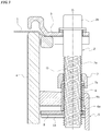
- FIGS. 1 to 3 show anti-loosening structures according to embodiments of the present invention, including a conventional tension bolt 2 (or adjustment bolt) for a drum, as shown in FIG. 5 , and a nut 7 attached thereto for generating prevailing torque.
- the tension bolt 2 may be made of metal and include a screw shaft 2a and a bolt head 2b that is integral to the base end of the screw shaft 2a, the bolt head 2b having a square or hexagonal cross-sectional shape.
- a flange may be provided on the lower edge of the bolt head 2b.
- a washer, made of metal or cloth, may be provided between the lower surface of the flange and the upper surface of a hoop 3, as shown.
- the hoop 3 as a whole, is ring-shaped, and is constructed to push a peripheral ring on the periphery of the drumhead 1 from above.
- a lug 5 is mounted on, and secured to, the shell 4 by a peg (not shown), for example.
- An attachment hole 5b is formed to be open on the top of the lug 5, and a threaded cylindrical pipe 6, shaped as a circular cylinder, is fitted into the attachment hole 5b from below.
- a flange 6a for engaging the lug 5 to prevent the pipe from rotating relative to the lug 5, the flange being shaped as a square plate, for example, where the flange 6a engages the inner periphery of the lug 5 to prevent the cylindrical pipe 6 from slipping upward through the attachment hole 5b.
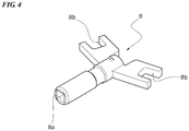
- a rib 5a is provided on the inner side wall of the lug 5, and a fixing plate 8 is inserted into a space between the rib and the flange 6a to prevent the cylindrical pipe 6 from slipping downward.
- the cylindrical pipe 6 may be made of metal, such as brass.
- a female screw is formed on the inner periphery of the cylindrical pipe 6 along the entire axial length.
- the screw shaft 2a of the tension bolt 2 is threadably mounted on the female screw of the cylindrical pipe 6.
- the upper end (or one end) of the cylindrical pipe 6 protrudes upward from the lug 5, and the nut 7 is threadably secured to a position on the screw shaft 2a that is located higher than the upper end of the cylindrical pipe 6.
- a recess 7a is provided on the bottom of the nut 7 (or one of the nut's sides as determined along the axial direction) for allowing the upper end of the cylindrical pipe 6 to be fitted therein.
- the hole thread of the nut 7 is not present in the axial range associated with the recess 7a; the hole thread is positioned higher than the recess 7a.
- the inner peripheral surface of the recess 7a of the nut 7 is a taper surface that decreases in diameter toward the interior and has an axis P slightly eccentric from the axis O of the threaded hole. Further, the maximum diameter of the taper surface, measured at its lower end, is larger than the outer diameter of the cylindrical pipe 6, and the minimum diameter of the taper surface, measured at its upper end, is substantially equal to or smaller than the outer diameter of the cylindrical pipe 6.
- the axis Q of the threaded hole of the nut 7 is eccentric and inclined from the axis O of the screw shaft 2a; as such, when the tension bolt 2 is loosened or tightened, the nut 7 does not corotate, making it possible to adjust the tension of the head 1 using the tension bolt 2 while appropriate prevailing torque is present.
- the axial tensile force generated in the screw shaft 2a of the tension bolt 2 and the prevailing torque produced by a so-called wedge effect in a lateral direction (i.e. direction perpendicular to the axial direction) generated on the screw shaft 2a by the nut 7 prevent the tension bolt 2 from loosening even during a heavy drumming session, thereby preventing the pitch of the drum (i.e., how high its sound is) from departing from the suitable range even toward the end of the piece, thus making it possible to achieve a performance with good sound up until the end of the concert.
- the present invention is not limited to the above-illustrated embodiments, and may be applied to anti-loosening structures for various adjustment bolts for tightening-force adjustments in various devices and appliances, or for various adjustment bolts for axial-position adjustments.
- the female screw is provided on the cylindrical pipe 6 in the above-illustrated embodiments, the female screw may be provided on the lug 5 or the screw shaft 2a may be threadably mounted on a female screw provided on another nut contained in the lug 5.
- the nut 7 is mounted with its threaded-hole axis inclined; alternatively, for some taper angles for the taper surface or for some size designs, the nut 7 may be mounted with its threaded-hole axis Q slightly eccentric from the axis O of the screw shaft 2a without the nut 7 being inclined, as shown in FIG. 3 ; in such implementations, again, the eccentricity of the axes from each other prevents the nut 7 from corotating with the screw shaft 2a.
Landscapes
- Engineering & Computer Science (AREA)
- General Engineering & Computer Science (AREA)
- Mechanical Engineering (AREA)
- Physics & Mathematics (AREA)
- Acoustics & Sound (AREA)
- Multimedia (AREA)
- Mutual Connection Of Rods And Tubes (AREA)
- Auxiliary Devices For Music (AREA)
Applications Claiming Priority (2)
| Application Number | Priority Date | Filing Date | Title |
|---|---|---|---|
| JP2017153797A JP6813890B2 (ja) | 2017-08-09 | 2017-08-09 | 調整ボルトの緩み止め構造 |
| PCT/JP2018/022180 WO2019031052A1 (fr) | 2017-08-09 | 2018-06-11 | Structure de verrouillage à boulon de réglage |
Publications (2)
| Publication Number | Publication Date |
|---|---|
| EP3667108A1 true EP3667108A1 (fr) | 2020-06-17 |
| EP3667108A4 EP3667108A4 (fr) | 2021-04-21 |
Family
ID=65272235
Family Applications (1)
| Application Number | Title | Priority Date | Filing Date |
|---|---|---|---|
| EP18842890.8A Withdrawn EP3667108A4 (fr) | 2017-08-09 | 2018-06-11 | Structure de verrouillage à boulon de réglage |
Country Status (4)
| Country | Link |
|---|---|
| US (1) | US11578750B2 (fr) |
| EP (1) | EP3667108A4 (fr) |
| JP (1) | JP6813890B2 (fr) |
| WO (1) | WO2019031052A1 (fr) |
Families Citing this family (3)
| Publication number | Priority date | Publication date | Assignee | Title |
|---|---|---|---|---|
| JP6813890B2 (ja) * | 2017-08-09 | 2021-01-13 | ハードロック工業株式会社 | 調整ボルトの緩み止め構造 |
| GB2574248B (en) * | 2018-05-31 | 2021-03-03 | Edwards Ltd | Foreline for a vacuum pump |
| CN110645254A (zh) * | 2019-09-27 | 2020-01-03 | 周峰 | 端面锥度定心互锁防松螺母套件 |
Family Cites Families (23)
| Publication number | Priority date | Publication date | Assignee | Title |
|---|---|---|---|---|
| US1832060A (en) * | 1929-11-27 | 1931-11-17 | T & S Corp | Nut lock |
| JPH032954Y2 (fr) * | 1986-07-26 | 1991-01-25 | ||
| JP3456547B2 (ja) * | 1994-05-09 | 2003-10-14 | 株式会社コルグ | ドラム |
| JPH116516A (ja) * | 1997-06-18 | 1999-01-12 | Hard Lock Kogyo Kk | 緩み止めナット |
| US6220801B1 (en) * | 1999-02-02 | 2001-04-24 | Chung-I Lin | Free-running-on, locking-off and tension directly indicated locking nut (frolo & TDI locking nut) |
| US6459026B1 (en) * | 2001-03-13 | 2002-10-01 | Terry J. Bozzio | Drum tensioner holding |
| US6686527B2 (en) * | 2001-06-11 | 2004-02-03 | Yamaha Corporation | Tightening frame for a drum |
| US20040081531A1 (en) * | 2002-10-28 | 2004-04-29 | Keane John Denison | Drum lug locking device |
| JP2005030584A (ja) * | 2003-06-18 | 2005-02-03 | Jm Engineering Kk | ボルト・ナットの緩み止め構造 |
| JP2008014402A (ja) | 2006-07-05 | 2008-01-24 | Hard Lock Industry Co Ltd | ボルトの緩み止め防止装置 |
| US20080173157A1 (en) * | 2007-01-18 | 2008-07-24 | Tsun-Chi Liao | Fastening dock structure for drums |
| JP4982660B2 (ja) | 2007-08-15 | 2012-07-25 | 株式会社コルグ | 打楽器 |
| JP5616023B2 (ja) * | 2009-01-07 | 2014-10-29 | ヤマハ株式会社 | スプリングの保持構造 |
| US8658875B2 (en) * | 2010-01-05 | 2014-02-25 | Gary T. Albright | Drum tuning and tuning stabilization mechanism |
| US11098748B2 (en) * | 2013-03-24 | 2021-08-24 | Crushlock, Inc. | One-piece self-locking nut |
| JP6437313B2 (ja) * | 2015-01-07 | 2018-12-12 | ハードロック工業株式会社 | 緩み止め特殊ダブルナット |
| US9679545B1 (en) * | 2016-09-20 | 2017-06-13 | Kuo-Chang Chen | Drum hoop fastening device and drum having the same |
| US20180204548A1 (en) * | 2017-01-17 | 2018-07-19 | Kuo-Chang Chen | Fastening device, drum hoop fastening device and drum having the same |
| JP6813890B2 (ja) * | 2017-08-09 | 2021-01-13 | ハードロック工業株式会社 | 調整ボルトの緩み止め構造 |
| JP6798704B2 (ja) * | 2017-10-27 | 2020-12-09 | 星野楽器株式会社 | ドラム用テンションボルトの緩み止め |
| JP2021165587A (ja) * | 2019-11-30 | 2021-10-14 | 合同会社Ysコーポレーション | 弛緩防止ナット |
| US11328698B2 (en) * | 2020-01-13 | 2022-05-10 | Drum Workshop, Inc. | Multipiece drum lug |
| TWI721764B (zh) * | 2020-01-22 | 2021-03-11 | 林家民 | 防鬆螺帽組 |
-
2017
- 2017-08-09 JP JP2017153797A patent/JP6813890B2/ja active Active
-
2018
- 2018-06-11 EP EP18842890.8A patent/EP3667108A4/fr not_active Withdrawn
- 2018-06-11 WO PCT/JP2018/022180 patent/WO2019031052A1/fr not_active Ceased
- 2018-06-11 US US16/630,749 patent/US11578750B2/en active Active
Also Published As
| Publication number | Publication date |
|---|---|
| WO2019031052A1 (fr) | 2019-02-14 |
| JP6813890B2 (ja) | 2021-01-13 |
| US20200166070A1 (en) | 2020-05-28 |
| JP2019032041A (ja) | 2019-02-28 |
| EP3667108A4 (fr) | 2021-04-21 |
| US11578750B2 (en) | 2023-02-14 |
Similar Documents
| Publication | Publication Date | Title |
|---|---|---|
| JP6934161B2 (ja) | 締結構造 | |
| EP3032119B1 (fr) | Ensemble boulon anti-desserrage | |
| US11578750B2 (en) | Anti-loosening adjustment bolt assembly | |
| JP6260843B1 (ja) | 緩まないロックナット | |
| JP2020532684A (ja) | 耐振ナットキット | |
| US12221994B2 (en) | Loosening prevention device | |
| US6459026B1 (en) | Drum tensioner holding | |
| JP6421307B2 (ja) | ねじ体の逆回転防止構造 | |
| JP7787558B2 (ja) | 緩み止め装置 | |
| JP2025021960A (ja) | 既設ナットの緩み止め装置 | |
| TW202511629A (zh) | 螺母的防鬆裝置 | |
| US10157599B2 (en) | Fastening device, drum hoop fastening device and drum having the same | |
| KR200345713Y1 (ko) | 너트 풀림방지구조 | |
| JP7043432B2 (ja) | 締結器具および締結構造 | |
| JP2023171040A (ja) | ナットの緩み止めキャップ | |
| EP3884175B1 (fr) | Agencement de fixation d'un écrou | |
| KR102360959B1 (ko) | 고정안정성 증대를 위한 체결요소 | |
| JP7290469B2 (ja) | 固定具及び音響センサ装置 | |
| JP7012035B2 (ja) | 締結器具 | |
| KR20210026477A (ko) | 고정안정성 증대를 위한 체결요소 | |
| US6956159B2 (en) | Drum head securement device | |
| JP2019143814A (ja) | ゆるみ止めボルト | |
| JP2020109312A (ja) | 締結器具、締結構造および締結方法 | |
| KR20000072765A (ko) | 진동 볼트 및 너트 | |
| JPH04160212A (ja) | 連結装置 |
Legal Events
| Date | Code | Title | Description |
|---|---|---|---|
| STAA | Information on the status of an ep patent application or granted ep patent |
Free format text: STATUS: THE INTERNATIONAL PUBLICATION HAS BEEN MADE |
|
| PUAI | Public reference made under article 153(3) epc to a published international application that has entered the european phase |
Free format text: ORIGINAL CODE: 0009012 |
|
| STAA | Information on the status of an ep patent application or granted ep patent |
Free format text: STATUS: REQUEST FOR EXAMINATION WAS MADE |
|
| 17P | Request for examination filed |
Effective date: 20200109 |
|
| AK | Designated contracting states |
Kind code of ref document: A1 Designated state(s): AL AT BE BG CH CY CZ DE DK EE ES FI FR GB GR HR HU IE IS IT LI LT LU LV MC MK MT NL NO PL PT RO RS SE SI SK SM TR |
|
| AX | Request for extension of the european patent |
Extension state: BA ME |
|
| DAV | Request for validation of the european patent (deleted) | ||
| DAX | Request for extension of the european patent (deleted) | ||
| A4 | Supplementary search report drawn up and despatched |
Effective date: 20210319 |
|
| RIC1 | Information provided on ipc code assigned before grant |
Ipc: F16B 39/12 20060101AFI20210315BHEP Ipc: F16B 37/00 20060101ALI20210315BHEP Ipc: F16B 39/284 20060101ALI20210315BHEP Ipc: G10D 13/00 20200101ALI20210315BHEP Ipc: G10D 13/02 20200101ALI20210315BHEP |
|
| STAA | Information on the status of an ep patent application or granted ep patent |
Free format text: STATUS: THE APPLICATION HAS BEEN WITHDRAWN |
|
| 18W | Application withdrawn |
Effective date: 20211007 |