EP3667133A1 - Vanne électromagnétique avec joint de piston unidirectionnel activé par pression - Google Patents
Vanne électromagnétique avec joint de piston unidirectionnel activé par pression Download PDFInfo
- Publication number
- EP3667133A1 EP3667133A1 EP20000044.6A EP20000044A EP3667133A1 EP 3667133 A1 EP3667133 A1 EP 3667133A1 EP 20000044 A EP20000044 A EP 20000044A EP 3667133 A1 EP3667133 A1 EP 3667133A1
- Authority
- EP
- European Patent Office
- Prior art keywords
- ring
- valve
- energizer
- valve member
- groove
- Prior art date
- Legal status (The legal status is an assumption and is not a legal conclusion. Google has not performed a legal analysis and makes no representation as to the accuracy of the status listed.)
- Withdrawn
Links
- 239000012530 fluid Substances 0.000 claims abstract description 28
- 210000004907 gland Anatomy 0.000 claims abstract description 11
- 238000007789 sealing Methods 0.000 claims abstract description 11
- 230000007704 transition Effects 0.000 claims description 2
- 229920001343 polytetrafluoroethylene Polymers 0.000 description 6
- 239000004810 polytetrafluoroethylene Substances 0.000 description 6
- 230000006835 compression Effects 0.000 description 2
- 238000007906 compression Methods 0.000 description 2
- 238000000034 method Methods 0.000 description 2
- 238000012986 modification Methods 0.000 description 2
- 230000004048 modification Effects 0.000 description 2
- 230000009977 dual effect Effects 0.000 description 1
- -1 polytetrafluoroethylene Polymers 0.000 description 1
Images


Classifications
-
- F—MECHANICAL ENGINEERING; LIGHTING; HEATING; WEAPONS; BLASTING
- F16—ENGINEERING ELEMENTS AND UNITS; GENERAL MEASURES FOR PRODUCING AND MAINTAINING EFFECTIVE FUNCTIONING OF MACHINES OR INSTALLATIONS; THERMAL INSULATION IN GENERAL
- F16K—VALVES; TAPS; COCKS; ACTUATING-FLOATS; DEVICES FOR VENTING OR AERATING
- F16K1/00—Lift valves or globe valves, i.e. cut-off apparatus with closure members having at least a component of their opening and closing motion perpendicular to the closing faces
- F16K1/32—Details
- F16K1/34—Cutting-off parts, e.g. valve members, seats
- F16K1/46—Attachment of sealing rings
-
- F—MECHANICAL ENGINEERING; LIGHTING; HEATING; WEAPONS; BLASTING
- F16—ENGINEERING ELEMENTS AND UNITS; GENERAL MEASURES FOR PRODUCING AND MAINTAINING EFFECTIVE FUNCTIONING OF MACHINES OR INSTALLATIONS; THERMAL INSULATION IN GENERAL
- F16J—PISTONS; CYLINDERS; SEALINGS
- F16J9/00—Piston-rings, e.g. non-metallic piston-rings, seats therefor; Ring sealings of similar construction
- F16J9/08—Piston-rings, e.g. non-metallic piston-rings, seats therefor; Ring sealings of similar construction with expansion obtained by pressure of the medium
-
- F—MECHANICAL ENGINEERING; LIGHTING; HEATING; WEAPONS; BLASTING
- F16—ENGINEERING ELEMENTS AND UNITS; GENERAL MEASURES FOR PRODUCING AND MAINTAINING EFFECTIVE FUNCTIONING OF MACHINES OR INSTALLATIONS; THERMAL INSULATION IN GENERAL
- F16J—PISTONS; CYLINDERS; SEALINGS
- F16J15/00—Sealings
- F16J15/16—Sealings between relatively-moving surfaces
- F16J15/164—Sealings between relatively-moving surfaces the sealing action depending on movements; pressure difference, temperature or presence of leaking fluid
-
- F—MECHANICAL ENGINEERING; LIGHTING; HEATING; WEAPONS; BLASTING
- F16—ENGINEERING ELEMENTS AND UNITS; GENERAL MEASURES FOR PRODUCING AND MAINTAINING EFFECTIVE FUNCTIONING OF MACHINES OR INSTALLATIONS; THERMAL INSULATION IN GENERAL
- F16J—PISTONS; CYLINDERS; SEALINGS
- F16J15/00—Sealings
- F16J15/46—Sealings with packing ring expanded or pressed into place by fluid pressure, e.g. inflatable packings
-
- F—MECHANICAL ENGINEERING; LIGHTING; HEATING; WEAPONS; BLASTING
- F16—ENGINEERING ELEMENTS AND UNITS; GENERAL MEASURES FOR PRODUCING AND MAINTAINING EFFECTIVE FUNCTIONING OF MACHINES OR INSTALLATIONS; THERMAL INSULATION IN GENERAL
- F16J—PISTONS; CYLINDERS; SEALINGS
- F16J15/00—Sealings
- F16J15/56—Other sealings for reciprocating rods
-
- F—MECHANICAL ENGINEERING; LIGHTING; HEATING; WEAPONS; BLASTING
- F16—ENGINEERING ELEMENTS AND UNITS; GENERAL MEASURES FOR PRODUCING AND MAINTAINING EFFECTIVE FUNCTIONING OF MACHINES OR INSTALLATIONS; THERMAL INSULATION IN GENERAL
- F16J—PISTONS; CYLINDERS; SEALINGS
- F16J9/00—Piston-rings, e.g. non-metallic piston-rings, seats therefor; Ring sealings of similar construction
- F16J9/12—Details
- F16J9/14—Joint-closures
-
- F—MECHANICAL ENGINEERING; LIGHTING; HEATING; WEAPONS; BLASTING
- F16—ENGINEERING ELEMENTS AND UNITS; GENERAL MEASURES FOR PRODUCING AND MAINTAINING EFFECTIVE FUNCTIONING OF MACHINES OR INSTALLATIONS; THERMAL INSULATION IN GENERAL
- F16K—VALVES; TAPS; COCKS; ACTUATING-FLOATS; DEVICES FOR VENTING OR AERATING
- F16K31/00—Actuating devices; Operating means; Releasing devices
- F16K31/02—Actuating devices; Operating means; Releasing devices electric; magnetic
- F16K31/06—Actuating devices; Operating means; Releasing devices electric; magnetic using a magnet, e.g. diaphragm valves, cutting off by means of a liquid
- F16K31/0644—One-way valve
- F16K31/0655—Lift valves
-
- F—MECHANICAL ENGINEERING; LIGHTING; HEATING; WEAPONS; BLASTING
- F16—ENGINEERING ELEMENTS AND UNITS; GENERAL MEASURES FOR PRODUCING AND MAINTAINING EFFECTIVE FUNCTIONING OF MACHINES OR INSTALLATIONS; THERMAL INSULATION IN GENERAL
- F16K—VALVES; TAPS; COCKS; ACTUATING-FLOATS; DEVICES FOR VENTING OR AERATING
- F16K31/00—Actuating devices; Operating means; Releasing devices
- F16K31/02—Actuating devices; Operating means; Releasing devices electric; magnetic
- F16K31/06—Actuating devices; Operating means; Releasing devices electric; magnetic using a magnet, e.g. diaphragm valves, cutting off by means of a liquid
- F16K31/0644—One-way valve
- F16K31/0655—Lift valves
- F16K31/0658—Armature and valve member being one single element
-
- F—MECHANICAL ENGINEERING; LIGHTING; HEATING; WEAPONS; BLASTING
- F16—ENGINEERING ELEMENTS AND UNITS; GENERAL MEASURES FOR PRODUCING AND MAINTAINING EFFECTIVE FUNCTIONING OF MACHINES OR INSTALLATIONS; THERMAL INSULATION IN GENERAL
- F16K—VALVES; TAPS; COCKS; ACTUATING-FLOATS; DEVICES FOR VENTING OR AERATING
- F16K31/00—Actuating devices; Operating means; Releasing devices
- F16K31/02—Actuating devices; Operating means; Releasing devices electric; magnetic
- F16K31/06—Actuating devices; Operating means; Releasing devices electric; magnetic using a magnet, e.g. diaphragm valves, cutting off by means of a liquid
- F16K31/0686—Braking, pressure equilibration, shock absorbing
- F16K31/0693—Pressure equilibration of the armature
Definitions
- the invention relates to a one-way pressure activated piston seal and method that provides low drag when not activated by pressure and low leakage when activated by pressure.
- piston seals using o-rings and polytetrafluoroethylene (PTFE) rings, sometimes referred to using the brand name TEFLONTM.
- PTFE polytetrafluoroethylene
- various types and configurations of piston seals are disclosed in U.S. Patent No. 7,815,195 , U.S. Patent No. 6,502,826 , U.S. Patent No. 6,129,358 , U.S. Patent No. 5,140,904 , U.S. Patent No. 5,082,295 , U.S. Patent No. 4,291,890 , U.S. Patent No. 4,109,921 , and U.S. Patent No. 3,592,164 . While these piston seals appear to be appropriate for their intended purposes, none of these configurations provide a pressure activated low-leak seal with low actuation drag.
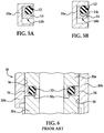
- a prior known solenoid actuated hydraulic fluid valve 30 includes first and second valve members 30a, 30b, which are movable with respect to one another.
- One of the valve members 30a includes a groove 30c formed therein.
- a standard o-ring 32 is located within the groove 30c and biases a PTFE ring 34 into sealing engagement with the other valve member 30b.
- This sealing system uses the o-ring 32 to load a PTFE-based seal ring 34 against the inside diameter (ID) of the piston bore 36 defined by the second valve member 30b.
- a one-way pressure activated piston seal can achieve the dual goals of low-leakage and low actuation drag for the hydraulic solenoid valve by sealing the valve in response to fluid pressure and by releasing the seal in response to initial solenoid actuator movement providing low actuation drag. It would be desirable to provide a high-flow, two-way, on/off hydraulic solenoid valve to close and hold a pressurized hydraulic accumulator with low leakage and then release and dump the accumulator with low actuation drag when requested.
- a one-way pressure activated piston seal can include two members movable axially relative to one another with a gland or groove formed in one of two members.
- An o-ring can be located within the groove in a non-contacting relationship to the other of the two members when in a non-energized state.
- An energizer ring can be located within the groove for reciprocation axially with respect to the o-ring, where the energizer ring moves axially toward the o-ring in response to fluid pressure against a surface opposite from the o-ring and compresses the o-ring, causing the o-ring to expand radially outwardly into sealing contact with the other of the two members.
- a method for sealing between two members movable axially with respect to one another in a one direction with low-leakage, while providing low drag in an opposite direction can include providing a gland or groove in one of the two members, positioning an o-ring in the groove in a non-contacting relationship with the other of the two members when in a non-energized state, and axially moving an energizer ring within the groove between first and second positions relative to the o-ring, where the energizer ring moves axially toward the o-ring in response to fluid pressure against a surface opposite from the o-ring and compresses the o-ring thereby causing axial compression of the o-ring and radial expansion of the o-ring into sealing contact with the other of the two members.
- a solenoid actuated valve for holding pressure and volume of an accumulator with low leakage and for providing low actuation drag during release stroke of the solenoid actuated valve for dumping fluid contents of the accumulator at very low current draw can include two valve members movable axially relative to one another with a gland or groove formed in one of two valve members, an o-ring located within the groove in non-contacting relationship to the other of the two valve members when in a non-energized state, and an energizer ring located within the groove for reciprocation axially with respect to the o-ring, where the energizer ring moves axially toward the o-ring in response to fluid pressure against a surface opposite from the o-ring and compresses the o-ring causing the o-ring to expand radially outwardly into sealing contact with the other of the two valve members.
- a solenoid actuated, fluid valve 10 is depicted for holding pressure and volume of an accumulator with low leakage and for providing low actuation drag during a release stroke of the solenoid actuated valve for dumping fluid contents of the accumulator at very low current draw.
- the fluid valve 10 can include two elongate valve members 10a, 10b capable of reciprocal movement axially relative to one another with a gland or groove 10c formed in one of two valve members 10a.
- an o-ring 12 is located within the groove 10c in non-contacting relationship to the other of the two valve members 10b when in a non-energized state.
- An energizer ring 14 is located within the gland or groove 10c for reciprocation axially with respect to the o-ring 12.
- the energizer ring 14 is illustrated as having a rectangular cross section, or square cross section, with a surface 14a on a side opposite from the o-ring 12. However, it should be recognized that the energizer ring 14 can have any desired cross section.
- the energizer ring 14 can have an L-shaped cross section 14b as illustrated in Figure 5A , or L-shaped cross section with an angled o-ring engaging surface 14c as illustrated in Figure 5B , or L-shaped cross section with a curved o-ring engaging surface, or a triangular shaped cross section, or any combination thereof.
- the energized ring 14 includes a surface 14a on a side opposite from the o-ring 12 allowing fluid pressure to act on surface 14a of the energizer ring 14 to drive the energizer ring 14 axially into compressive engagement with the o-ring.
- the energizer ring 14 moves axially toward the o-ring 12 against a surface 14a opposite from the o-ring 12. While in the fluid pressure energized state, the energizer ring 14 compresses the o-ring 12 causing the o-ring 12 to expand radially outwardly into sealing contact with the other of the two valve members 10b. The o-ring 12 is held in a radially outwardly expanded energized state by the energizer ring 14 in response to the fluid pressure acting on surface 14a.
- the one-way pressure activated piston seal assembly 20 was developed to resolve a sealing challenge related to a low-leak, high-flow, two-way, on/off, solenoid operated, hydraulic fluid valve.
- the solenoid operated fluid valve 10 is used to close and hold a pressurized hydraulic accumulator and then release and dump the accumulator when requested. In order hold the pressure and volume of the accumulator, the solenoid operated fluid valve 10 has very demanding leakage requirements. Additionally, the solenoid operated fluid valve 10 needs to be able to stroke and dump the accumulator at very low current draw and therefore needs to have low actuation drag.
- the solenoid operated fluid valve 10 is illustrated with the solenoid armature 10a acting as a piston and with a gland 10c on the outside diameter (OD) that accommodates an o-ring 12 and an energizing ring 14. Without pressure, the o-ring 12 sits in the gland 10c and is clear of the piston bore 26 defined by the inside diameter (ID) of the valve body 10b.
- the energizing ring 14 is designed as a clearance fit to the bore 26 as well, so there is little to no seal drag.
- the energizer ring 14 compresses the o-ring 12 forcing the outside diameter (OD) of the o-ring 12 out and into contact with the piston ring 10b and seals the piston bore 26.
- the solenoid 18 is commanded to actuate and dump the accumulator, the piston 10a moves up and unloads the o-ring 12 allowing the o-ring 12 to retract from the piston bore 26 and eliminate the drag.
Landscapes
- Engineering & Computer Science (AREA)
- General Engineering & Computer Science (AREA)
- Mechanical Engineering (AREA)
- Physics & Mathematics (AREA)
- Architecture (AREA)
- Fluid Mechanics (AREA)
- Magnetically Actuated Valves (AREA)
- Sealing Devices (AREA)
- Supply Devices, Intensifiers, Converters, And Telemotors (AREA)
Applications Claiming Priority (3)
| Application Number | Priority Date | Filing Date | Title |
|---|---|---|---|
| US201261611506P | 2012-03-15 | 2012-03-15 | |
| PCT/US2013/029492 WO2013138144A1 (fr) | 2012-03-15 | 2013-03-07 | Joint de piston unidirectionnel activé par pression |
| EP13761402.0A EP2825800B1 (fr) | 2012-03-15 | 2013-03-07 | Joint de piston unidirectionnel activé par pression |
Related Parent Applications (2)
| Application Number | Title | Priority Date | Filing Date |
|---|---|---|---|
| EP13761402.0A Division EP2825800B1 (fr) | 2012-03-15 | 2013-03-07 | Joint de piston unidirectionnel activé par pression |
| EP13761402.0A Division-Into EP2825800B1 (fr) | 2012-03-15 | 2013-03-07 | Joint de piston unidirectionnel activé par pression |
Publications (1)
| Publication Number | Publication Date |
|---|---|
| EP3667133A1 true EP3667133A1 (fr) | 2020-06-17 |
Family
ID=49161668
Family Applications (2)
| Application Number | Title | Priority Date | Filing Date |
|---|---|---|---|
| EP20000044.6A Withdrawn EP3667133A1 (fr) | 2012-03-15 | 2013-03-07 | Vanne électromagnétique avec joint de piston unidirectionnel activé par pression |
| EP13761402.0A Active EP2825800B1 (fr) | 2012-03-15 | 2013-03-07 | Joint de piston unidirectionnel activé par pression |
Family Applications After (1)
| Application Number | Title | Priority Date | Filing Date |
|---|---|---|---|
| EP13761402.0A Active EP2825800B1 (fr) | 2012-03-15 | 2013-03-07 | Joint de piston unidirectionnel activé par pression |
Country Status (6)
| Country | Link |
|---|---|
| US (2) | US9732857B2 (fr) |
| EP (2) | EP3667133A1 (fr) |
| JP (2) | JP6177870B2 (fr) |
| KR (1) | KR101986573B1 (fr) |
| CN (1) | CN104145145B (fr) |
| WO (1) | WO2013138144A1 (fr) |
Families Citing this family (11)
| Publication number | Priority date | Publication date | Assignee | Title |
|---|---|---|---|---|
| US9732857B2 (en) | 2012-03-15 | 2017-08-15 | Borgwarner Inc. | One-way pressure activated piston seal |
| US9599249B2 (en) * | 2012-08-31 | 2017-03-21 | Borgwarner Inc. | Two-way flow control solenoid with an auto pressure regulating feature |
| US10174860B2 (en) | 2015-03-30 | 2019-01-08 | Aisin Aw Co., Ltd. | Electromagnetic valve and transmission-use fuel pressure control device using electromagnetic valve |
| DE102015116909A1 (de) * | 2015-10-05 | 2017-04-06 | Kendrion (Villingen) Gmbh | Elektromagnetisches Schaltventil |
| KR101821597B1 (ko) * | 2016-05-10 | 2018-01-26 | 영도산업 주식회사 | 유체 제어용 솔레노이드 밸브 |
| US10428743B2 (en) * | 2017-03-07 | 2019-10-01 | Hamilton Sundstrand Corporation | Drop-tight spool and sleeve for metering valve |
| CN111720565A (zh) * | 2019-03-19 | 2020-09-29 | 浙江盾安禾田金属有限公司 | 电磁阀 |
| CN111589390B (zh) * | 2020-06-02 | 2021-10-26 | 无锡职业技术学院 | 一种适用于超高压反应釜搅拌轴的轴封装置 |
| CN112610708B (zh) * | 2020-12-09 | 2021-11-02 | 浙江大学 | 一种双座式调节阀及其密封结构和方法 |
| US12553535B2 (en) * | 2022-04-27 | 2026-02-17 | Solero Technologies LLC | Solenoid valve assembly and method of operating the same |
| DE102024123126A1 (de) * | 2024-08-13 | 2026-02-19 | Wagner GmbH & Co. Fahrzeugteilefabrik KG | Elektromagnetisches Ventil für kurze Schaltzeiten |
Citations (11)
| Publication number | Priority date | Publication date | Assignee | Title |
|---|---|---|---|---|
| US3592164A (en) | 1969-04-01 | 1971-07-13 | Gen Motors Corp | Shock absorber piston rod seal assembly with belleville washer |
| DD131780A1 (de) * | 1977-04-25 | 1978-07-19 | Hoffmann Ulf Rainer | Bremseinrichtung fuer federrueckstellende ventile |
| US4109921A (en) | 1976-05-27 | 1978-08-29 | Taunus-Armaturen Gmbh | Seal for pistons and piston rods of cylinder-type actuators |
| US4291890A (en) | 1979-10-15 | 1981-09-29 | Mcdonnell Douglas Corporation | Valve seal with O-ring and backup ring |
| US5082295A (en) | 1989-12-02 | 1992-01-21 | Firma Carl Freudenberg | Piston or rod seal |
| US5140904A (en) | 1990-06-29 | 1992-08-25 | Alfred Teves Gmbh | Piston sealing arrangement for pressure-fluid-operated systems |
| US6129358A (en) | 1997-12-23 | 2000-10-10 | Caterpillar Inc. | Unidirectional rod sealing ring for a hydraulic cylinder |
| US6502826B1 (en) | 2000-10-30 | 2003-01-07 | Caterpillar Inc | Hydraulic cylinder piston seal |
| EP1876378A1 (fr) * | 2005-04-27 | 2008-01-09 | Eagle Industry Co., Ltd. | Structure d'etancheite et clapet de commande l'utilisant |
| US20080245427A1 (en) * | 2007-04-05 | 2008-10-09 | Mac Valves, Inc. | Balanced solenoid valve |
| US7815195B2 (en) | 2003-03-14 | 2010-10-19 | Gapi Technische Produkte Gmbh | Sealing ring and sealing ring arrangement |
Family Cites Families (33)
| Publication number | Priority date | Publication date | Assignee | Title |
|---|---|---|---|---|
| US1751445A (en) * | 1927-03-31 | 1930-03-18 | Prosperity Co Inc | Piston construction |
| US2456356A (en) * | 1947-12-09 | 1948-12-14 | Joseph S Aber | Packing gasket and static seal |
| US2809080A (en) * | 1953-11-23 | 1957-10-08 | North American Aviation Inc | Anti-extrusion device for annular seals |
| US3525530A (en) * | 1968-06-10 | 1970-08-25 | Gen Motors Corp | High pressure-low friction seal |
| US3556474A (en) * | 1968-08-19 | 1971-01-19 | Domer Scaramucci | Dual sealed ball valves |
| US3749357A (en) * | 1972-04-07 | 1973-07-31 | Acf Ind Inc | Valve structure having fluid pressure actuated seats |
| US3930657A (en) * | 1972-08-07 | 1976-01-06 | Skega Aktiebolag | Device for sealing between preferably movable parts |
| CA1021225A (fr) * | 1974-06-28 | 1977-11-22 | General Signal Corporation | Vanne a ouverture rapide |
| FR2287329A1 (fr) * | 1974-10-08 | 1976-05-07 | Commissariat Energie Atomique | Dispositif d'etancheite pour presse de filage ou de compression |
| US4027816A (en) * | 1975-04-18 | 1977-06-07 | Bowen Tools, Inc. | Seal assembly |
| US4053166A (en) * | 1975-12-08 | 1977-10-11 | Halogen Insulator & Seal Corporation | Two-piece seal |
| AT348170B (de) * | 1977-03-25 | 1979-02-12 | Voest Ag | Anfahrstrang fuer stranggiessanlagen |
| US4469017A (en) | 1983-02-23 | 1984-09-04 | Dover Corporation | Static leak seal assembly for use in fluid containing machinery |
| JPS6086680U (ja) * | 1983-11-18 | 1985-06-14 | エスエムシ−株式会社 | 直動形電磁弁 |
| DE3443220C1 (de) * | 1984-11-27 | 1988-08-18 | Walter 8700 Würzburg Hunger | Dichteinheit und Verfahren zur Herstellung derselben |
| DE3834610A1 (de) * | 1988-10-11 | 1990-04-12 | Loegel Jun | Pumpenaggregat |
| US5143382A (en) | 1991-03-04 | 1992-09-01 | W. S. Shamban & Company | Pressure relieving slipper seal system |
| CN2179492Y (zh) * | 1992-09-24 | 1994-10-12 | 余毅钦 | 超高压往复杆复合动密封 |
| US5437436A (en) * | 1993-08-20 | 1995-08-01 | Ni-Tech, Inc. | Stand-alone gas spring |
| US5451065A (en) * | 1994-05-23 | 1995-09-19 | Stein Seal Company | Seal structures |
| US6158744A (en) * | 1995-07-03 | 2000-12-12 | Smiths Industries Plc | Seal arrangement providing a seal between a bore and a rod movable in the bore |
| JP3543617B2 (ja) * | 1998-04-30 | 2004-07-14 | Nok株式会社 | 密封装置 |
| US6648337B1 (en) * | 1998-11-14 | 2003-11-18 | Polymer Sealing Solutions, Inc. | Backup ring with controlled spacing |
| DE10014644A1 (de) * | 2000-03-24 | 2001-10-11 | Infineon Technologies Ag | Optisches Modul zur Wellenlängen-Referenzmessung in WDM-Systemen |
| US6481454B2 (en) * | 2000-08-16 | 2002-11-19 | Gilmore Valve Co., Ltd. | Regulator with segmented body |
| JP2002156043A (ja) * | 2000-11-20 | 2002-05-31 | Nok Corp | 密封装置 |
| US7341258B2 (en) * | 2004-09-24 | 2008-03-11 | Greene, Tweed Of Delaware, Inc. | Cammed seal assembly with sealing ring having an angled leg portion and foot portion with elastomeric energizer element |
| US7793944B2 (en) * | 2004-12-28 | 2010-09-14 | Nok Corporation | Sealing device |
| US8297314B2 (en) * | 2006-06-21 | 2012-10-30 | Hunter Industries, Inc. | Solenoid actuated pilot valve for irrigation system valve |
| CA2667320A1 (fr) * | 2009-06-08 | 2010-12-08 | Noetic Technologies Inc. | Ensemble d'etancheite |
| DE102010033647B4 (de) * | 2010-08-06 | 2021-08-05 | Stasskol Gmbh | Vorrichtung zum Abdichten einer Stange gegenüber einem Medium und Verfahren zum Abdichten einer Stange gegenüber einem Medium |
| CN101975277A (zh) * | 2010-10-26 | 2011-02-16 | 中国航天科技集团公司第五研究院第五一○研究所 | 一种f型滑环式组合双侧动密封装置 |
| US9732857B2 (en) | 2012-03-15 | 2017-08-15 | Borgwarner Inc. | One-way pressure activated piston seal |
-
2013
- 2013-03-07 US US14/383,172 patent/US9732857B2/en active Active
- 2013-03-07 KR KR1020147027166A patent/KR101986573B1/ko active Active
- 2013-03-07 EP EP20000044.6A patent/EP3667133A1/fr not_active Withdrawn
- 2013-03-07 EP EP13761402.0A patent/EP2825800B1/fr active Active
- 2013-03-07 CN CN201380011591.6A patent/CN104145145B/zh active Active
- 2013-03-07 WO PCT/US2013/029492 patent/WO2013138144A1/fr not_active Ceased
- 2013-03-07 JP JP2015500465A patent/JP6177870B2/ja active Active
-
2017
- 2017-07-12 JP JP2017136008A patent/JP6371888B2/ja active Active
- 2017-07-17 US US15/651,571 patent/US9970552B2/en active Active
Patent Citations (11)
| Publication number | Priority date | Publication date | Assignee | Title |
|---|---|---|---|---|
| US3592164A (en) | 1969-04-01 | 1971-07-13 | Gen Motors Corp | Shock absorber piston rod seal assembly with belleville washer |
| US4109921A (en) | 1976-05-27 | 1978-08-29 | Taunus-Armaturen Gmbh | Seal for pistons and piston rods of cylinder-type actuators |
| DD131780A1 (de) * | 1977-04-25 | 1978-07-19 | Hoffmann Ulf Rainer | Bremseinrichtung fuer federrueckstellende ventile |
| US4291890A (en) | 1979-10-15 | 1981-09-29 | Mcdonnell Douglas Corporation | Valve seal with O-ring and backup ring |
| US5082295A (en) | 1989-12-02 | 1992-01-21 | Firma Carl Freudenberg | Piston or rod seal |
| US5140904A (en) | 1990-06-29 | 1992-08-25 | Alfred Teves Gmbh | Piston sealing arrangement for pressure-fluid-operated systems |
| US6129358A (en) | 1997-12-23 | 2000-10-10 | Caterpillar Inc. | Unidirectional rod sealing ring for a hydraulic cylinder |
| US6502826B1 (en) | 2000-10-30 | 2003-01-07 | Caterpillar Inc | Hydraulic cylinder piston seal |
| US7815195B2 (en) | 2003-03-14 | 2010-10-19 | Gapi Technische Produkte Gmbh | Sealing ring and sealing ring arrangement |
| EP1876378A1 (fr) * | 2005-04-27 | 2008-01-09 | Eagle Industry Co., Ltd. | Structure d'etancheite et clapet de commande l'utilisant |
| US20080245427A1 (en) * | 2007-04-05 | 2008-10-09 | Mac Valves, Inc. | Balanced solenoid valve |
Also Published As
| Publication number | Publication date |
|---|---|
| US20170314684A1 (en) | 2017-11-02 |
| JP6177870B2 (ja) | 2017-08-09 |
| JP2015511689A (ja) | 2015-04-20 |
| KR20140134307A (ko) | 2014-11-21 |
| JP6371888B2 (ja) | 2018-08-08 |
| CN104145145A (zh) | 2014-11-12 |
| US9732857B2 (en) | 2017-08-15 |
| WO2013138144A1 (fr) | 2013-09-19 |
| KR101986573B1 (ko) | 2019-06-07 |
| US9970552B2 (en) | 2018-05-15 |
| EP2825800A1 (fr) | 2015-01-21 |
| EP2825800A4 (fr) | 2015-12-09 |
| CN104145145B (zh) | 2017-12-01 |
| EP2825800B1 (fr) | 2020-04-15 |
| JP2017215043A (ja) | 2017-12-07 |
| US20150041693A1 (en) | 2015-02-12 |
Similar Documents
| Publication | Publication Date | Title |
|---|---|---|
| US9970552B2 (en) | One-way pressure activated piston seal | |
| US6361049B1 (en) | Recessed groove/seal surface for seal effectiveness | |
| US20120210868A1 (en) | Packing assembly for a pump | |
| EP1437536B1 (fr) | Bague anti-extrusion pour joint élastomère ainsi que bride | |
| CN110410574B (zh) | 具有一体的密封件的致动器衬套 | |
| US12467541B2 (en) | Seal assemblies and related valves and methods | |
| US10527121B2 (en) | Overtravel pressure relief for a gas spring | |
| US8870187B2 (en) | Shaft seal for down-hole tools | |
| US11655902B2 (en) | Failsafe close valve assembly | |
| JP2007139055A (ja) | 密封装置および密封構造 | |
| EP3258144A1 (fr) | Ensemble segment de piston | |
| JPH07217608A (ja) | アクチュエータのためのシール組立体 | |
| US7770899B1 (en) | Pressure actuated seal carrier | |
| US11448229B2 (en) | Seal assembly | |
| CN223049304U (zh) | 一种活塞平衡阀结构及气弹簧 | |
| AU2014237310B2 (en) | Piston with sealing pressed by pressure of an internal piston chamber | |
| CA3038445A1 (fr) | Ensemble d`etancheite | |
| CN119412460A (zh) | 一种双向活塞平衡阀结构及气弹簧 | |
| JP2008157299A (ja) | 超高圧シール構造 |
Legal Events
| Date | Code | Title | Description |
|---|---|---|---|
| PUAI | Public reference made under article 153(3) epc to a published international application that has entered the european phase |
Free format text: ORIGINAL CODE: 0009012 |
|
| STAA | Information on the status of an ep patent application or granted ep patent |
Free format text: STATUS: THE APPLICATION HAS BEEN PUBLISHED |
|
| AC | Divisional application: reference to earlier application |
Ref document number: 2825800 Country of ref document: EP Kind code of ref document: P |
|
| AK | Designated contracting states |
Kind code of ref document: A1 Designated state(s): AL AT BE BG CH CY CZ DE DK EE ES FI FR GB GR HR HU IE IS IT LI LT LU LV MC MK MT NL NO PL PT RO RS SE SI SK SM TR |
|
| STAA | Information on the status of an ep patent application or granted ep patent |
Free format text: STATUS: THE APPLICATION IS DEEMED TO BE WITHDRAWN |
|
| 18D | Application deemed to be withdrawn |
Effective date: 20201218 |