EP3667169B1 - Buse de pulvérisation de carburant - Google Patents
Buse de pulvérisation de carburant Download PDFInfo
- Publication number
- EP3667169B1 EP3667169B1 EP19208446.5A EP19208446A EP3667169B1 EP 3667169 B1 EP3667169 B1 EP 3667169B1 EP 19208446 A EP19208446 A EP 19208446A EP 3667169 B1 EP3667169 B1 EP 3667169B1
- Authority
- EP
- European Patent Office
- Prior art keywords
- primary
- wall
- spray nozzle
- splitter
- fuel
- Prior art date
- Legal status (The legal status is an assumption and is not a legal conclusion. Google has not performed a legal analysis and makes no representation as to the accuracy of the status listed.)
- Active
Links
Images


Classifications
-
- F—MECHANICAL ENGINEERING; LIGHTING; HEATING; WEAPONS; BLASTING
- F23—COMBUSTION APPARATUS; COMBUSTION PROCESSES
- F23R—GENERATING COMBUSTION PRODUCTS OF HIGH PRESSURE OR HIGH VELOCITY, e.g. GAS-TURBINE COMBUSTION CHAMBERS
- F23R3/00—Continuous combustion chambers using liquid or gaseous fuel
- F23R3/28—Continuous combustion chambers using liquid or gaseous fuel characterised by the fuel supply
-
- F—MECHANICAL ENGINEERING; LIGHTING; HEATING; WEAPONS; BLASTING
- F23—COMBUSTION APPARATUS; COMBUSTION PROCESSES
- F23R—GENERATING COMBUSTION PRODUCTS OF HIGH PRESSURE OR HIGH VELOCITY, e.g. GAS-TURBINE COMBUSTION CHAMBERS
- F23R3/00—Continuous combustion chambers using liquid or gaseous fuel
- F23R3/02—Continuous combustion chambers using liquid or gaseous fuel characterised by the air-flow or gas-flow configuration
- F23R3/04—Air inlet arrangements
- F23R3/10—Air inlet arrangements for primary air
- F23R3/12—Air inlet arrangements for primary air inducing a vortex
- F23R3/14—Air inlet arrangements for primary air inducing a vortex by using swirl vanes
-
- F—MECHANICAL ENGINEERING; LIGHTING; HEATING; WEAPONS; BLASTING
- F23—COMBUSTION APPARATUS; COMBUSTION PROCESSES
- F23R—GENERATING COMBUSTION PRODUCTS OF HIGH PRESSURE OR HIGH VELOCITY, e.g. GAS-TURBINE COMBUSTION CHAMBERS
- F23R3/00—Continuous combustion chambers using liquid or gaseous fuel
- F23R3/28—Continuous combustion chambers using liquid or gaseous fuel characterised by the fuel supply
- F23R3/286—Continuous combustion chambers using liquid or gaseous fuel characterised by the fuel supply having fuel-air premixing devices
-
- F—MECHANICAL ENGINEERING; LIGHTING; HEATING; WEAPONS; BLASTING
- F23—COMBUSTION APPARATUS; COMBUSTION PROCESSES
- F23R—GENERATING COMBUSTION PRODUCTS OF HIGH PRESSURE OR HIGH VELOCITY, e.g. GAS-TURBINE COMBUSTION CHAMBERS
- F23R3/00—Continuous combustion chambers using liquid or gaseous fuel
- F23R3/28—Continuous combustion chambers using liquid or gaseous fuel characterised by the fuel supply
- F23R3/30—Continuous combustion chambers using liquid or gaseous fuel characterised by the fuel supply comprising fuel prevapourising devices
-
- F—MECHANICAL ENGINEERING; LIGHTING; HEATING; WEAPONS; BLASTING
- F23—COMBUSTION APPARATUS; COMBUSTION PROCESSES
- F23R—GENERATING COMBUSTION PRODUCTS OF HIGH PRESSURE OR HIGH VELOCITY, e.g. GAS-TURBINE COMBUSTION CHAMBERS
- F23R3/00—Continuous combustion chambers using liquid or gaseous fuel
- F23R3/28—Continuous combustion chambers using liquid or gaseous fuel characterised by the fuel supply
- F23R3/34—Feeding into different combustion zones
- F23R3/343—Pilot flames, i.e. fuel nozzles or injectors using only a very small proportion of the total fuel to insure continuous combustion
-
- F—MECHANICAL ENGINEERING; LIGHTING; HEATING; WEAPONS; BLASTING
- F23—COMBUSTION APPARATUS; COMBUSTION PROCESSES
- F23D—BURNERS
- F23D2900/00—Special features of, or arrangements for burners using fluid fuels or solid fuels suspended in a carrier gas
- F23D2900/11101—Pulverising gas flow impinging on fuel from pre-filming surface, e.g. lip atomizers
-
- F—MECHANICAL ENGINEERING; LIGHTING; HEATING; WEAPONS; BLASTING
- F23—COMBUSTION APPARATUS; COMBUSTION PROCESSES
- F23R—GENERATING COMBUSTION PRODUCTS OF HIGH PRESSURE OR HIGH VELOCITY, e.g. GAS-TURBINE COMBUSTION CHAMBERS
- F23R3/00—Continuous combustion chambers using liquid or gaseous fuel
- F23R3/28—Continuous combustion chambers using liquid or gaseous fuel characterised by the fuel supply
- F23R3/34—Feeding into different combustion zones
- F23R3/346—Feeding into different combustion zones for staged combustion
-
- Y—GENERAL TAGGING OF NEW TECHNOLOGICAL DEVELOPMENTS; GENERAL TAGGING OF CROSS-SECTIONAL TECHNOLOGIES SPANNING OVER SEVERAL SECTIONS OF THE IPC; TECHNICAL SUBJECTS COVERED BY FORMER USPC CROSS-REFERENCE ART COLLECTIONS [XRACs] AND DIGESTS
- Y02—TECHNOLOGIES OR APPLICATIONS FOR MITIGATION OR ADAPTATION AGAINST CLIMATE CHANGE
- Y02T—CLIMATE CHANGE MITIGATION TECHNOLOGIES RELATED TO TRANSPORTATION
- Y02T50/00—Aeronautics or air transport
- Y02T50/60—Efficient propulsion technologies, e.g. for aircraft
Definitions
- the present disclosure relates to a fuel spray nozzle for a combustor in a gas turbine engine.
- Fuel spray nozzles are a type of injector used in gas turbine engines to provide fuel to combustors for combustion.
- the fuel spray nozzle atomises fuel and ejects the atomised fuel into the combustor for more effective combustion.
- European Patent Application EP 1719950 A2 discloses a lean burn fuel nozzle for a gas turbine engine.
- the nozzle comprising a main air swirler defined in part by a main inner air passage having a radially inner wall with a diverging downstream surface.
- an intermediate air swirler which is located radially inward of the main inner air swirler and allows cooling air flow to be created along the downstream surface of the radially inner wall of the main inner air passage, and a radially inner pilot fuel delivery system radially inward of the intermediate air swirler.
- United States Patent Application US 2012/047903 A1 discloses a fuel injector for a gas turbine engine.
- the injector has a nozzle having a main air swirler and an intermediate air swirler.
- the intermediate air circuit provides a film of cooling air along the surface of the air swirler.
- European Patent Application EP 1413830 A2 discloses a fuel injector for a gas turbine engine having a modified air splitter.
- the air splitter includes at least one aft end cone angled radially outboard and axially positioned downstream of the main airblast fuel injector aft end.
- the air splitter is used to divide a pilot air stream exiting the pilot swirler from an inner main air stream which exits the inner main swirler, these two airstreams dorm a bifurcated recirculation zone.
- United States Patent Application US 2017/299183 A1 discloses a method of operating a lean premix burner for a gas turbine engine.
- the burner having an annular air passage having a primary air supply with a swirl imparted by a swirler on the outside of the main burner and a second air supply which can be supplied at different points of the burner.
- WO 2008/071902 A1 discloses a fuel injector head for a gas turbine engine.
- the head comprises a pilot injector and a main injector located radially outwardly of the pilot injector.
- a splitter separates the pilot injector from the main injector and acts as a boundary duct through which fuel is injected by the pilot injector flows.
- the splitter is hollow to improve cooling.
- European Patent Application EP 1391653 A2 discloses a fuel injection arrangement comprising a body having main and pilot injectors. An air splitter is provided to separate the air flow exiting the pilot injector and the main injector thereby creating a bifurcated recirculation zone between the main and pilot air flow.
- the present disclosure provides fuel spray nozzle, a combustor, and a gas turbine engine, as set out in the appended claims.
- a fuel spray nozzle for a combustor in a gas turbine engine, the fuel spray nozzle comprising: a primary atomiser configured to discharge a primary flow of swirled atomised fuel along and around a fuel spray nozzle axis, the primary atomiser comprising a primary outer air swirler disposed radially outwardly of a primary fuel pre-filmer channel; and a secondary atomiser around the primary atomiser comprising a secondary inner air swirler configured to swirl flow along a secondary inner air channel, the secondary inner air swirler being disposed radially inwardly of a secondary fuel pre-filmer channel of the secondary atomiser.
- a primary outer air channel is defined between the primary outer air swirler and the secondary inner air swirler.
- the secondary inner air swirler comprises a splitter wall configured to separate swirling flow in the secondary inner air channel from the primary flow of atomised fuel.
- the secondary inner air swirler comprises a primary cap wall integral with and extending radially inwardly from the splitter wall to direct flow from the primary outer air channel inwardly towards the fuel spray nozzle axis.
- the primary cap wall comprises splitter cooling holes configured to admit air from the primary outer air channel to form a cooling film along the splitter wall.
- the splitter wall comprises a conical portion extending with a radially outward component along a downstream direction along the fuel spray nozzle axis.
- the primary cap wall comprises a conical wall configured to direct flow from the primary outer air channel towards the fuel spray nozzle axis, and a radially-extending wall between the splitter wall and the conical wall.
- the primary cap wall comprises splitter cooling holes configured to admit air from the outer primary air channel to form a cooling film along the splitter wall.
- the splitter cooling holes may be provided in a portion of the primary cap wall between the radially-extending wall and the splitter wall.
- the splitter cooling holes may be provided at a junction between the primary cap wall and the splitter wall.
- the splitter cooling holes may be configured to impart a radially outward component to an air flow therethrough to direct cooling air towards the splitter wall.
- the splitter cooling holes may be configured to impart a tangential component to an air flow therethrough to direct the cooling air towards the splitter wall.
- the conical wall of the primary cap wall may comprise cooling holes for cooling the primary cap wall.
- the splitter wall may also comprise an array of effusion cooling holes There may be no separate component in the space defined between the primary outer air swirler and the secondary inner air swirler.
- the primary atomiser may comprise an inner primary swirler disposed radially inwardly of the primary fuel pre-filmer channel.
- the inner primary swirler may be configured to swirl a flow of air along the fuel spray nozzle axis.
- the secondary atomiser may comprise an outer secondary swirler radially outwardly of a secondary fuel pre-filmer channel.
- the outer secondary swirler may be configured to swirl a flow of air into the path of flow from the secondary inner air swirler.
- a combustor comprising a fuel spray nozzle in accordance with the first aspect.
- a gas turbine engine comprising a combustor in accordance with the second aspect.
- Such a gas turbine engine may comprise an engine core comprising a turbine, a combustor, a compressor, and a core shaft connecting the turbine to the compressor.
- a gas turbine engine may comprise a fan (having fan blades) located upstream of the engine core.
- the gas turbine engine may comprise a gearbox that receives an input from the core shaft and outputs drive to the fan so as to drive the fan at a lower rotational speed than the core shaft.
- the input to the gearbox may be directly from the core shaft, or indirectly from the core shaft, for example via a spur shaft and/or gear.
- the core shaft may rigidly connect the turbine and the compressor, such that the turbine and compressor rotate at the same speed (with the fan rotating at a lower speed).
- the gas turbine engine as described and/or claimed herein may have any suitable general architecture.
- the gas turbine engine may have any desired number of shafts that connect turbines and compressors, for example one, two or three shafts.
- the turbine connected to the core shaft may be a first turbine
- the compressor connected to the core shaft may be a first compressor
- the core shaft may be a first core shaft.
- the engine core may further comprise a second turbine, a second compressor, and a second core shaft connecting the second turbine to the second compressor.
- the second turbine, second compressor, and second core shaft may be arranged to rotate at a higher rotational speed than the first core shaft.
- the second compressor may be positioned axially downstream of the first compressor.
- the second compressor may be arranged to receive (for example directly receive, for example via a generally annular duct) flow from the first compressor.
- the gearbox may be arranged to be driven by the core shaft that is configured to rotate (for example in use) at the lowest rotational speed (for example the first core shaft in the example above).
- the gearbox may be arranged to be driven only by the core shaft that is configured to rotate (for example in use) at the lowest rotational speed (for example only be the first core shaft, and not the second core shaft, in the example above).
- the gearbox may be arranged to be driven by any one or more shafts, for example the first and/or second shafts in the example above.
- the gearbox is a reduction gearbox (in that the output to the fan is a lower rotational rate than the input from the core shaft).
- Any type of gearbox may be used.
- the gearbox may be a "planetary” or “star” gearbox, as described in more detail elsewhere herein.
- the gearbox may have any desired reduction ratio (defined as the rotational speed of the input shaft divided by the rotational speed of the output shaft), for example greater than 2.5, for example in the range of from 3 to 4.2, for example on the order of or at least 3, 3.1, 3.2, 3.3, 3.4, 3.5, 3.6, 3.7, 3.8, 3.9, 4, 4.1 or 4.2.
- the gear ratio may be, for example, between any two of the values in the previous sentence. A higher gear ratio may be more suited to "planetary" style gearbox. In some arrangements, the gear ratio may be outside these ranges.
- a combustor may be provided axially downstream of the fan and compressor(s).
- the combustor may be directly downstream of (for example at the exit of) the second compressor, where a second compressor is provided.
- the flow at the exit to the combustor may be provided to the inlet of the second turbine, where a second turbine is provided.
- the combustor may be provided upstream of the turbine(s).
- each compressor may comprise any number of stages, for example multiple stages.
- Each stage may comprise a row of rotor blades and a row of stator vanes, which may be variable stator vanes (in that their angle of incidence may be variable).
- the row of rotor blades and the row of stator vanes may be axially offset from each other.
- each turbine may comprise any number of stages, for example multiple stages.
- Each stage may comprise a row of rotor blades and a row of stator vanes.
- the row of rotor blades and the row of stator vanes may be axially offset from each other.
- Each fan blade may be defined as having a radial span extending from a root (or hub) at a radially inner gas-washed location, or 0% span position, to a tip at a 100% span position.
- the ratio of the radius of the fan blade at the hub to the radius of the fan blade at the tip may be less than (or on the order of) any of: 0.4, 0.39, 0.38 0.37, 0.36, 0.35, 0.34, 0.33, 0.32, 0.31, 0.3, 0.29, 0.28, 0.27, 0.26, or 0.25.
- the ratio of the radius of the fan blade at the hub to the radius of the fan blade at the tip may be in an inclusive range bounded by any two of the values in the previous sentence (i.e.
- the values may form upper or lower bounds). These ratios may commonly be referred to as the hub-to-tip ratio.
- the radius at the hub and the radius at the tip may both be measured at the leading edge (or axially forwardmost) part of the blade.
- the hub-to-tip ratio refers, of course, to the gas-washed portion of the fan blade, i.e. the portion radially outside any platform.
- the radius of the fan may be measured between the engine centreline and the tip of a fan blade at its leading edge.
- the fan diameter (which may simply be twice the radius of the fan) may be greater than (or on the order of) any of: 250 cm (around 100 inches), 260 cm, 270 cm (around 105 inches), 280 cm (around 110 inches), 290 cm (around 115 inches), 300 cm (around 120 inches), 310 cm, 320 cm (around 125 inches), 330 cm (around 130 inches), 340 cm (around 135 inches), 350cm, 360cm (around 140 inches), 370 cm (around 145 inches), 380 (around 150 inches) cm or 390 cm (around 155 inches).
- the fan diameter may be in an inclusive range bounded by any two of the values in the previous sentence (i.e. the values may form upper or lower bounds).
- the rotational speed of the fan may vary in use. Generally, the rotational speed is lower for fans with a higher diameter. Purely by way of non-limitative example, the rotational speed of the fan at cruise conditions may be less than 2500 rpm, for example less than 2300 rpm. Purely by way of further non-limitative example, the rotational speed of the fan at cruise conditions for an engine having a fan diameter in the range of from 250 cm to 300 cm (for example 250 cm to 280 cm) may be in the range of from 1700 rpm to 2500 rpm, for example in the range of from 1800 rpm to 2300 rpm, for example in the range of from 1900 rpm to 2100 rpm.
- the rotational speed of the fan at cruise conditions for an engine having a fan diameter in the range of from 320 cm to 380 cm may be in the range of from 1200 rpm to 2000 rpm, for example in the range of from 1300 rpm to 1800 rpm, for example in the range of from 1400 rpm to 1600 rpm.
- the fan In use of the gas turbine engine, the fan (with associated fan blades) rotates about a rotational axis. This rotation results in the tip of the fan blade moving with a velocity Utip.
- the work done by the fan blades 13 on the flow results in an enthalpy rise dH of the flow.
- a fan tip loading may be defined as dH/Utip2, where dH is the enthalpy rise (for example the 1-D average enthalpy rise) across the fan and Utip is the (translational) velocity of the fan tip, for example at the leading edge of the tip (which may be defined as fan tip radius at leading edge multiplied by angular speed).
- the fan tip loading at cruise conditions may be greater than (or on the order of) any of: 0.3, 0.31, 0.32, 0.33, 0.34, 0.35, 0.36, 0.37, 0.38, 0.39 or 0.4 (all units in this paragraph being Jkg-1K-1/(ms-1)2).
- the fan tip loading may be in an inclusive range bounded by any two of the values in the previous sentence (i.e. the values may form upper or lower bounds).
- Gas turbine engines in accordance with the present disclosure may have any desired bypass ratio, where the bypass ratio is defined as the ratio of the mass flow rate of the flow through the bypass duct to the mass flow rate of the flow through the core at cruise conditions.
- the bypass ratio may be greater than (or on the order of) any of the following: 10, 10.5, 11, 11.5, 12, 12.5, 13, 13.5, 14, 14.5, 15, 15.5, 16, 16.5, 17, 17.5, 18,18.5, 19, 19.5, or 20.
- the bypass ratio may be in an inclusive range bounded by any two of the values in the previous sentence (i.e. the values may form upper or lower bounds).
- the bypass duct may be substantially annular.
- the bypass duct may be radially outside the engine core.
- the radially outer surface of the bypass duct may be defined by a nacelle and/or a fan case.
- the overall pressure ratio of a gas turbine engine as described and/or claimed herein may be defined as the ratio of the stagnation pressure upstream of the fan to the stagnation pressure at the exit of the highest pressure compressor (before entry into the combustor).
- the overall pressure ratio of a gas turbine engine as described and/or claimed herein at cruise may be greater than (or on the order of) any of the following: 35, 40, 45, 50, 55, 60, 65, 70, 75.
- the overall pressure ratio may be in an inclusive range bounded by any two of the values in the previous sentence (i.e. the values may form upper or lower bounds).
- Specific thrust of an engine may be defined as the net thrust of the engine divided by the total mass flow through the engine. At cruise conditions, the specific thrust of an engine described and/or claimed herein may be less than (or on the order of) any of the following: 110 Nkg-1s, 105 Nkg-1s, 100 Nkg-1s, 95 Nkg-1s, 90 Nkg-1s, 85 Nkg-1s or 80 Nkg-1s.
- the specific thrust may be in an inclusive range bounded by any two of the values in the previous sentence (i.e. the values may form upper or lower bounds). Such engines may be particularly efficient in comparison with conventional gas turbine engines.
- a gas turbine engine as described and/or claimed herein may have any desired maximum thrust.
- a gas turbine as described and/or claimed herein may be capable of producing a maximum thrust of at least (or on the order of) any of the following: 160kN, 170kN, 180kN, 190kN, 200kN, 250kN, 300kN, 350kN, 400kN, 450kN, 500kN, or 550kN.
- the maximum thrust may be in an inclusive range bounded by any two of the values in the previous sentence (i.e. the values may form upper or lower bounds).
- the thrust referred to above may be the maximum net thrust at standard atmospheric conditions at sea level plus 15 °C (ambient pressure 101.3kPa, temperature 30 °C), with the engine static.
- the temperature of the flow at the entry to the high pressure turbine may be particularly high.
- This temperature which may be referred to as TET
- TET may be measured at the exit to the combustor, for example immediately upstream of the first turbine vane, which itself may be referred to as a nozzle guide vane.
- the TET may be at least (or on the order of) any of the following: 1400K, 1450K, 1500K, 1550K, 1600K or 1650K.
- the TET at cruise may be in an inclusive range bounded by any two of the values in the previous sentence (i.e. the values may form upper or lower bounds).
- the maximum TET in use of the engine may be, for example, at least (or on the order of) any of the following: 1700K, 1750K, 1800K, 1850K, 1900K, 1950K or 2000K.
- the maximum TET may be in an inclusive range bounded by any two of the values in the previous sentence (i.e. the values may form upper or lower bounds).
- the maximum TET may occur, for example, at a high thrust condition, for example at a maximum take-off (MTO) condition.
- MTO maximum take-off
- a fan blade and/or aerofoil portion of a fan blade described and/or claimed herein may be manufactured from any suitable material or combination of materials.
- at least a part of the fan blade and/or aerofoil may be manufactured at least in part from a composite, for example a metal matrix composite and/or an organic matrix composite, such as carbon fibre.
- at least a part of the fan blade and/or aerofoil may be manufactured at least in part from a metal, such as a titanium based metal or an aluminium based material (such as an aluminium-lithium alloy) or a steel based material.
- the fan blade may comprise at least two regions manufactured using different materials.
- the fan blade may have a protective leading edge, which may be manufactured using a material that is better able to resist impact (for example from birds, ice or other material) than the rest of the blade.
- a leading edge may, for example, be manufactured using titanium or a titanium-based alloy.
- the fan blade may have a carbon-fibre or aluminium based body (such as an aluminium lithium alloy) with a titanium leading edge.
- a fan as described and/or claimed herein may comprise a central portion, from which the fan blades may extend, for example in a radial direction.
- the fan blades may be attached to the central portion in any desired manner.
- each fan blade may comprise a fixture which may engage a corresponding slot in the hub (or disc).
- a fixture may be in the form of a dovetail that may slot into and/or engage a corresponding slot in the hub/disc in order to fix the fan blade to the hub/disc.
- the fan blades maybe formed integrally with a central portion. Such an arrangement may be referred to as a blisk or a bling. Any suitable method may be used to manufacture such a blisk or bling.
- VAN variable area nozzle
- the general principles of the present disclosure may apply to engines with or without a VAN.
- the fan of a gas turbine as described and/or claimed herein may have any desired number of fan blades, for example 14, 16, 18, 20, 22, 24 or 26 fan blades.
- cruise conditions may mean cruise conditions of an aircraft to which the gas turbine engine is attached.
- cruise conditions may be conventionally defined as the conditions at mid-cruise, for example the conditions experienced by the aircraft and/or engine at the midpoint (in terms of time and/or distance) between top of climb and start of decent.
- the forward speed at the cruise condition may be any point in the range of from Mach 0.7 to 0.9, for example 0.75 to 0.85, for example 0.76 to 0.84, for example 0.77 to 0.83, for example 0.78 to 0.82, for example 0.79 to 0.81, for example on the order of Mach 0.8, on the order of Mach 0.85 or in the range of from 0.8 to 0.85.
- Any single speed within these ranges may be the cruise condition.
- the cruise conditions may be outside these ranges, for example below Mach 0.7 or above Mach 0.9.
- the cruise conditions may correspond to standard atmospheric conditions at an altitude that is in the range of from 10000m to 15000m, for example in the range of from 10000m to 12000m, for example in the range of from 10400m to 11600m (around 38000 ft), for example in the range of from 10500m to 11500m, for example in the range of from 10600m to 11400m, for example in the range of from 10700m (around 35000 ft) to 11300m, for example in the range of from 10800m to 11200m, for example in the range of from 10900m to 11100m, for example on the order of 11000m.
- the cruise conditions may correspond to standard atmospheric conditions at any given altitude in these ranges.
- the cruise conditions may correspond to: a forward Mach number of 0.8; a pressure of 23000 Pa; and a temperature of -55 °C.
- “cruise” or “cruise conditions” may mean the aerodynamic design point.
- Such an aerodynamic design point may correspond to the conditions (comprising, for example, one or more of the Mach Number, environmental conditions and thrust requirement) for which the fan is designed to operate. This may mean, for example, the conditions at which the fan (or gas turbine engine) is designed to have optimum efficiency.
- a gas turbine engine described and/or claimed herein may operate at the cruise conditions defined elsewhere herein.
- cruise conditions may be determined by the cruise conditions (for example the mid-cruise conditions) of an aircraft to which at least one (for example 2 or 4) gas turbine engine may be mounted in order to provide propulsive thrust.
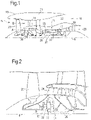
- FIG. 1 illustrates a gas turbine engine 10 having a principal rotational axis 9.
- the engine 10 comprises an air intake 12 and a propulsive fan 23 that generates two airflows: a core airflow A and a bypass airflow B.
- the gas turbine engine 10 comprises a core 11 that receives the core airflow A.
- the engine core 11 comprises, in axial flow series, a low pressure compressor 14, a high-pressure compressor 15, combustion equipment 16, a high-pressure turbine 17, a low pressure turbine 19 and a core exhaust nozzle 20.
- a nacelle 21 surrounds the gas turbine engine 10 and defines a bypass duct 22 and a bypass exhaust nozzle 18.
- the bypass airflow B flows through the bypass duct 22.
- the fan 23 is attached to and driven by the low pressure turbine 19 via a shaft 26 and an epicyclic gearbox 30.
- the core airflow A is accelerated and compressed by the low pressure compressor 14 and directed into the high pressure compressor 15 where further compression takes place.
- the compressed air exhausted from the high pressure compressor 15 is directed into the combustion equipment 16 where it is mixed with fuel and the mixture is combusted.
- the resultant hot combustion products then expand through, and thereby drive, the high pressure and low pressure turbines 17, 19 before being exhausted through the core exhaust nozzle 20 to provide some propulsive thrust.
- the high pressure turbine 17 drives the high pressure compressor 15 by a suitable interconnecting shaft 27.
- the fan 23 generally provides the majority of the propulsive thrust.
- the epicyclic gearbox 30 is a reduction gearbox.
- FIG. 2 An exemplary arrangement for a geared fan gas turbine engine 10 is shown in Figure 2 .
- the low pressure turbine 19 (see Figure 1 ) drives the shaft 26, which is coupled to a sun wheel, or sun gear, 28 of the epicyclic gear arrangement 30.
- a sun wheel, or sun gear, 28 of the epicyclic gear arrangement 30 Radially outwardly of the sun gear 28 and intermeshing therewith is a plurality of planet gears 32 that are coupled together by a planet carrier 34.
- the planet carrier 34 constrains the planet gears 32 to precess around the sun gear 28 in synchronicity whilst enabling each planet gear 32 to rotate about its own axis.
- the planet carrier 34 is coupled via linkages 36 to the fan 23 in order to drive its rotation about the engine axis 9.
- an annulus or ring gear 39 Radially outwardly of the planet gears 32 and intermeshing therewith is an annulus or ring gear 39 that is coupled, via linkages 43, to a stationary supporting structure 24.
- low pressure turbine and “low pressure compressor” as used herein may be taken to mean the lowest pressure turbine stages and lowest pressure compressor stages (i.e. not including the fan 23) respectively and/or the turbine and compressor stages that are connected together by the interconnecting shaft 26 with the lowest rotational speed in the engine (i.e. not including the gearbox output shaft that drives the fan 23).
- the "low pressure turbine” and “low pressure compressor” referred to herein may alternatively be known as the "intermediate pressure turbine” and “intermediate pressure compressor”. Where such alternative nomenclature is used, the fan 23 may be referred to as a first, or lowest pressure, compression stage.
- the epicyclic gearbox 30 is shown by way of example in greater detail in Figure 3 .
- Each of the sun gear 28, planet gears 32 and ring gear 39 comprise teeth about their periphery to intermesh with the other gears. However, for clarity only exemplary portions of the teeth are illustrated in Figure 3 .
- Practical applications of a planetary epicyclic gearbox 30 generally comprise at least three planet gears 32.
- the epicyclic gearbox 30 illustrated by way of example in Figures 2 and 3 is of the planetary type, in that the planet carrier 34 is coupled to an output shaft via linkages 36, with the ring gear 39 fixed.
- the epicyclic gearbox 30 may be a star arrangement, in which the planet carrier 34 is held fixed, with the ring (or annulus) gear 39 allowed to rotate. In such an arrangement the fan 23 is driven by the ring gear 39.
- the gearbox 30 may be a differential gearbox in which the ring gear 39 and the planet carrier 34 are both allowed to rotate.
- any suitable arrangement may be used for locating the gearbox 30 in the engine 10 and/or for connecting the gearbox 30 to the engine 10.
- the connections (such as the linkages 36, 43 in the Figure 2 example) between the gearbox 30 and other parts of the engine 10 (such as the input shaft 26, the output shaft and the fixed structure 24) may have any desired degree of stiffness or flexibility.
- any suitable arrangement of the bearings between rotating and stationary parts of the engine may be used, and the disclosure is not limited to the exemplary arrangement of Figure 2 .
- the gearbox 30 has a star arrangement (described above)
- the skilled person would readily understand that the arrangement of output and support linkages and bearing locations would typically be different to that shown by way of example in Figure 2 .
- the present disclosure extends to a gas turbine engine having any arrangement of gearbox styles (for example star or planetary), support structures, input and output shaft arrangement, and bearing locations.
- gearbox styles for example star or planetary
- support structures for example star or planetary
- input and output shaft arrangement for example star or planetary
- bearing locations for example star or planetary
- the gearbox may drive additional and/or alternative components (e.g. the intermediate pressure compressor and/or a booster compressor).
- additional and/or alternative components e.g. the intermediate pressure compressor and/or a booster compressor.
- gas turbine engines to which the present disclosure may be applied may have alternative configurations.
- such engines may have an alternative number of compressors and/or turbines and/or an alternative number of interconnecting shafts.
- the gas turbine engine shown in Figure 1 has a split flow nozzle 18, 20 meaning that the flow through the bypass duct 22 has its own nozzle 18 that is separate to and radially outside the core exhaust nozzle 20.
- this is not limiting, and any aspect of the present disclosure may also apply to engines in which the flow through the bypass duct 22 and the flow through the core 11 are mixed, or combined, before (or upstream of) a single nozzle, which may be referred to as a mixed flow nozzle.
- One or both nozzles may have a fixed or variable area.
- the described example relates to a turbofan engine, the disclosure may apply, for example, to any type of gas turbine engine, such as an open rotor (in which the fan stage is not surrounded by a nacelle) or turboprop engine, for example.
- the gas turbine engine 10 may not comprise a gearbox 30.
- the geometry of the gas turbine engine 10, and components thereof, is defined by a conventional axis system, comprising an axial direction (which is aligned with the rotational axis 9), a radial direction (in the bottom-to-top direction in Figure 1 ), and a circumferential direction (perpendicular to the page in the Figure 1 view).
- the axial, radial and circumferential directions are mutually perpendicular.
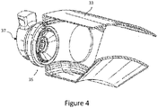
- Figure 4 shows a cutaway view of an annular combustor 33 of a gas turbine engine 10 defining a combustion chamber having an inlet 35 at an upstream end for receiving a fuel spray nozzle 37.
- the fuel spray nozzle 37 is configured to receive fuel and to atomise the fuel so as to eject atomised fuel into the combustor 33 for combustion.
- FIG. 5 shows a cross-sectional side view of the fuel spray nozzle 37.
- the fuel spray nozzle has a generally circular profile from a front view.
- the fuel spray nozzle 37 comprises a primary atomiser 38 and a secondary atomiser 40.
- the primary atomiser is a central or pilot swirler, and the secondary atomiser is disposed radially outside of the primary swirler to surround it.
- the secondary atomiser may be referred to as a peripheral atomiser in that it surrounds the primary atomiser.
- the primary atomiser 38 is configured to receive fuel, to receive an air flow at an upstream end, and to discharge a primary flow of atomised fuel into the combustion chamber.
- the secondary atomiser 40 is disposed circumferentially around the primary atomiser 38 and is configured to receive fuel, air flow at an upstream end, and to discharge a secondary flow of atomised fuel into the combustion chamber.
- the primary and secondary atomisers may be provided as a common assembly, and may be wholly or partially integral with one another. The functional division between them will become clear from the following description. However, for clarity, a nominal dividing line 41 between the components of the primary and secondary atomisers 38, 40 is shown in Figure 5 . The dividing line 41 is shown only on one side of the fuel spray nozzle cross-section to show features of the fuel spray nozzle more clearly.
- the primary atomiser 38 receives fuel in low flow conditions, and the secondary atomiser 40 receives fuel together with the primary atomiser 38 in high flow conditions.
- the primary atomiser 38 comprises a primary inner air swirler 42, a primary fuel pre-filmer 44 and a primary outer air swirler 48.
- the primary inner air swirler 42 is disposed radially inwardly from the primary fuel pre-filmer 44 and the primary outer air swirler 48 is disposed radially outwardly from the primary fuel pre-filmer 44.
- a primary inner air channel 56 is defined radially within (i.e. inwardly of) the primary fuel pre-filmer 44.
- the inner air swirler 42 is disposed within the primary inner air channel 56 and in this example comprises a central post 52 (otherwise known as a "bullet") having a plurality of vanes 54 distributed around the central post 52 and configured to impart a tangential velocity component to generate a swirling flow (e.g. helical).
- the central post 52 is aligned with a fuel spray nozzle axis 50 and the vanes 54 swirl air flowing through the primary inner air channel 56 (i.e. rotate or twist by imparting a circumferential/tangential component to the flow).
- the primary fuel pre-filmer 44 defines an annular primary fuel pre-filmer channel 46.
- the primary fuel pre-filmer channel 46 is configured to receive pressurised fuel from a fuel source (not shown) and to eject an annular film of fuel from an outlet downstream of the primary inner air swirler 42.
- the secondary atomiser 40 comprises a secondary inner air swirler 60, a secondary fuel pre-filmer 62 disposed radially outwardly from the secondary inner air swirler 60, and a secondary outer air swirler 64 disposed radially outwardly of the secondary fuel pre-filmer 62.
- a primary outer air channel 58 is defined between the primary outer air swirler 48 and the secondary inner air swirler 60.
- the primary outer air swirler 48 comprises a plurality of vanes 45 distributed around a support provided by the primary fuel pre-filmer 44 which are configured to swirl air flowing through the primary outer air channel 58.
- a secondary inner air channel 68 is defined between the secondary inner air swirler 60 and the secondary fuel pre-filmer 62.
- a secondary outer air channel 70 is defined between the secondary fuel pre-filmer 62 and the secondary outer air swirler 64.
- the secondary fuel pre-filmer 62 defines an annular secondary fuel pre-filmer channel 63.
- the annular secondary fuel pre-filmer channel 63 is configured to receive pressurised fuel from a fuel source (not shown) and to eject an annular film of fuel from an outlet by the secondary inner air channel 68.
- the secondary outer air swirler 64 comprises a peripheral support and a plurality of vanes 65 distributed around and radially inwardly from the peripheral support for swirling air flow through the secondary outer air channel 70.
- the secondary outer air swirler 64 is configured so that the secondary outer air channel 70 is generally conical and extends with a radially inward component in a downstream direction along the fuel spray nozzle axis 50.
- the secondary inner air swirler 60 comprises a splitter wall 66 having an upstream annular portion 66a, and a downstream conical portion 66b extending with a radially outward component from the annular portion 66a in a downstream direction along the fuel spray nozzle axis 50.
- the upstream annular portion 66a of the splitter wall 66 comprises a plurality of vanes 76 distributed around an outer surface of the annular portion 66a of the splitter wall 66 to swirl air flowing through the secondary inner air channel 68.
- the annular portion 66a is configured to separate the swirling flow in the secondary inner air channel 68 from the swirling flow in the primary outer channel 58.
- the secondary outer air channel 70 and the secondary inner air channel 68 are configured so that their respective air flows collide (shown in Figure 5 ). Between the secondary inner channel 68 and the secondary outer channel 70, the secondary fuel pre-filmer 62 ejects the film of fuel which collides with these air flows. These colliding swirled flows atomise the fuel in the fuel film, so that the secondary atomiser 40 ejects a secondary flow of atomised fuel into the combustion chamber.
- the secondary inner air swirler 60 further comprises a primary cap wall 72 which is disposed downstream of the outlet of the primary fuel pre-filmer 44.
- the primary cap wall 72 is integral with the splitter wall 66 and comprises a conical wall portion extending with a radially inward component in a downstream direction along the fuel spray nozzle axis 50 to direct flow from the primary outer air channel 58 radially inwardly towards the fuel spray nozzle axis 50.
- the primary cap wall 72 comprises a substantially radially-extending wall portion between the conical wall portion and the splitter wall 66, in particular extending from a junction between the annular portion 66a and the conical portion 66b of the splitter wall 66.
- the primary cap wall 72 is configured to direct swirled flow in the primary outer air channel 58 radially inwardly in a downstream direction so as to direct the flow into the path of the film of fuel from the primary fuel pre-filmer 44 and into the swirling flow from the primary inner air channel 56.
- the collision of these flows results in atomisation of the fuel so that the primary atomiser 38 discharges a primary flow of atomised fuel in a similar manner to the secondary atomiser 40.
- the primary flow of atomised fuel is combusted in the combustion chamber in use, as well as the secondary flow of atomised fuel, such that the radially inner surface of the conical portion 66b of the splitter wall 66 may be exposed to high combustion temperatures, typically above a sustainable temperature for metal.
- the downstream surface of the primary cap wall 72 facing the combustion chamber may also exposed to these high temperatures.
- These surfaces of the splitter 66 and the primary cap wall 72 may be cooled during use to temperatures lower than the temperature of combustion in the combustor, to thereby minimise damage sustained by these components and extend their useful life.
- the primary cap wall 72 comprises a plurality of splitter cooling holes 80 distributed circumferentially around the secondary inner air swirler 60 and configured to admit allow air flow from the primary outer air channel 58 through the primary cap wall 72 to form a cooling film along the radially inner surface of the splitter wall 66.
- the splitter cooling holes 80 are provided in a portion of the primary cap wall 72 between the primary cap wall 72 and the splitter wall 66. In this example, the splitter cooling holes 80 are provided at a junction between the primary cap wall 72 and the splitter wall 66.
- the splitter cooling holes 80 extend with a radially outward component in a downstream direction to impart a radially outward component to air flow through the splitter cooling holes 80. This helps to direct the cooling air along the surface of the conical portion 66b of the splitter wall 66. Further, the splitter cooling holes 80 extend with a tangential component in the primary cap wall 72 in order to also impart a tangential component to the air flow through the splitter cooling holes 80. This imparts a swirl to the air flow, and a centrifugal force, further helping to direct the cooling air towards the surface of the conical portion 66b of the splitter wall 66.
- the conical wall of the primary cap wall 72 also comprises an array of cooling holes 82 (e.g. circumferentially distributed around the primary cap wall 72) for cooling the surface of the primary cap wall 72 which may be exposed to the combustion chamber with air from the primary outer air channel 58.
- the primary cap wall may comprise more than one array of cooling holes at different radial locations which are circumferentially distributed around the primary cap wall.
- the primary cap wall 72 there are no cooling holes provided on the substantially radially-extending wall portion of the primary cap wall 72. This is so that the primary cap wall 72 can be easily replaced on the secondary inner air swirler 60 of the fuel spray nozzle 37.
- the radially-extending wall provides a flat surface which can easily be cut to remove the conical wall of the primary cap wall 72 and which provides a suitable surface to provide a new conical wall to the secondary inner air swirler 60 (for example by welding or additive manufacture).
- a second example secondary inner air swirler 90 is shown in Figure 6 isolated from a fuel spray nozzle in an isometric view.
- the second example secondary inner air swirler 90 has all of the same features as the first example secondary inner air swirler 60 as described above with reference to Figure 5 , including the splitter cooling holes 80 and the array of cooling holes 80 in the primary cap wall 72.
- the conical portion 66b of the splitter wall 66 additionally comprises an array of effusion cooling holes 84 around the splitter wall 66.
- These effusion cooling holes 84 provide further cooling of the conical portion 66b of the splitter wall 66 in use, as the air flowing in the secondary inner air channel 68 passes through the effusion cooling holes 84 to cool the conical portion 66b of the splitter wall 66.
- the splitter wall comprises an upstream annular portion and a downstream conical portion
- the splitter wall may have an upstream and downstream annular portion.
- the splitter cooling holes may not extend with a radially outward component.
- the fuel spray nozzle 37 having a secondary inner air swirler as described above provides a compact solution for cooling the splitter wall.
- an additional component was provided between the primary outer air swirler and the secondary inner air swirler to direct the flows. With the arrangement of this invention, no such additional component is required. Therefore, manufacturing of the fuel spray nozzle is simpler such that manufacturing costs are reduced and the fuel spray nozzle can be made more compact. This may also result in a weight saving compared to previously considered arrangements.
Landscapes
- Engineering & Computer Science (AREA)
- Chemical & Material Sciences (AREA)
- Combustion & Propulsion (AREA)
- Mechanical Engineering (AREA)
- General Engineering & Computer Science (AREA)
- Structures Of Non-Positive Displacement Pumps (AREA)
Claims (11)
- Buse de pulvérisation de carburant (37) pour une chambre de combustion dans un moteur à turbine à gaz (10), la buse de pulvérisation de carburant (37) comprenant :un atomiseur primaire (38) conçu pour décharger un flux primaire de carburant atomisé tourbillonnant le long et autour d'un axe de buse de pulvérisation de carburant (50), l'atomiseur primaire (38) comprenant une coupelle de turbulence d'air externe primaire (48) disposée radialement vers l'extérieur d'un canal de pré-filmeur de carburant primaire (46) ; etun atomiseur secondaire (40) autour de l'atomiseur primaire (38) comprenant une coupelle de turbulence d'air interne secondaire (60, 90) conçue pour faire tourbillonner le flux le long d'un canal d'air interne secondaire (68), la coupelle de turbulence d'air interne secondaire (60, 90) étant disposée radialement vers l'intérieur d'un canal de pré-filmeur de carburant secondaire (63) de l'atomiseur secondaire (40) ;un canal d'air externe primaire (58) étant défini entre la coupelle de turbulence d'air externe primaire (48) et la coupelle de turbulence d'air interne secondaire (60, 90) ;ladite coupelle de turbulence d'air interne secondaire (60, 90) comprenant une paroi séparatrice (66) conçue pour séparer le flux tourbillonnant dans le canal d'air interne secondaire (68) du flux primaire de carburant atomisé ; etladite coupelle de turbulence d'air interne secondaire (60, 90) comprenant une paroi de capuchon primaire (72) solidaire de la paroi séparatrice (66) et s'étendant radialement vers l'intérieur à partir de celle-ci pour diriger le flux du canal d'air externe primaire (58) vers l'intérieur vers l'axe de buse de pulvérisation de carburant (50) ;caractérisé en ce que la paroi de capuchon primaire (72) comprend des trous de refroidissement de séparateur (80) conçus pour admettre de l'air provenant du canal d'air externe primaire (58) afin de former un film de refroidissement le long de la paroi séparatrice (66) et ladite paroi de capuchon primaire (72) comprenant une paroi conique conçue pour diriger le flux provenant du canal d'air externe primaire (58) vers l'axe de buse de pulvérisation de carburant (50), et une paroi s'étendant radialement entre la paroi séparatrice (66) et la paroi conique.
- Buse de pulvérisation de carburant (37) selon la revendication 1, ladite paroi séparatrice (66) comprenant une partie conique (66b) s'étendant avec une composante radialement vers l'extérieur le long d'une direction en aval le long de l'axe de buse de pulvérisation de carburant (50).
- Buse de pulvérisation de carburant (37) selon la revendication 1 ou 2, lesdits trous de refroidissement de séparateur (80) étant ménagés dans une partie de la paroi de capuchon primaire (72) entre la paroi s'étendant radialement et la paroi séparatrice (66).
- Buse de pulvérisation de carburant (37) selon la revendication 3, lesdits trous de refroidissement de séparateur (80) étant conçus pour conférer une composante radialement vers l'extérieur à un flux d'air à travers eux pour diriger l'air de refroidissement vers la paroi séparatrice (66).
- Buse de pulvérisation de carburant (37) selon la revendication 3 ou 4, lesdits trous de refroidissement de séparateur (80) étant conçus pour conférer une composante tangentielle à un flux d'air à travers eux pour diriger l'air de refroidissement vers la paroi séparatrice (66).
- Buse de pulvérisation de carburant (37) selon l'une quelconque des revendications 1, 3 ou 4, ladite paroi conique de la paroi de capuchon primaire (72) comprenant des trous de refroidissement (82) en vue du refroidissement la paroi de capuchon primaire (72).
- Buse de pulvérisation de carburant (37) selon une quelconque revendication précédente, ladite paroi séparatrice (66) comprenant également un réseau de trous de refroidissement d'effusion (84).
- Buse de pulvérisation de carburant (37) selon une quelconque revendication précédente, ledit atomiseur primaire (38) comprenant une coupelle de turbulence primaire interne (42) disposée radialement vers l'intérieur du canal de pré-filmeur de carburant primaire (46), ladite coupelle de turbulence primaire interne (42) étant conçue pour faire tourbillonner un flux d'air le long de l'axe de buse de pulvérisation de carburant (50).
- Buse de pulvérisation de carburant (37) selon une quelconque revendication précédente, ledit atomiseur secondaire (40) comprenant une coupelle de turbulence secondaire externe (64) radialement vers l'extérieur d'un canal de pré-filmeur de carburant secondaire (63), ladite coupelle de turbulence secondaire externe (64) étant conçue pour faire tourbillonner un flux d'air dans le trajet de flux en provenance de la coupelle de turbulence d'air interne secondaire (60, 90).
- Chambre de combustion (33) comprenant une buse de pulvérisation de carburant (37) selon une quelconque revendication précédente.
- Moteur à turbine à gaz (10) comprenant une chambre de combustion (33) conformément à la revendication 10.
Applications Claiming Priority (1)
| Application Number | Priority Date | Filing Date | Title |
|---|---|---|---|
| GBGB1820206.9A GB201820206D0 (en) | 2018-12-12 | 2018-12-12 | A fuel spray nozzle |
Publications (2)
| Publication Number | Publication Date |
|---|---|
| EP3667169A1 EP3667169A1 (fr) | 2020-06-17 |
| EP3667169B1 true EP3667169B1 (fr) | 2022-04-27 |
Family
ID=65030180
Family Applications (1)
| Application Number | Title | Priority Date | Filing Date |
|---|---|---|---|
| EP19208446.5A Active EP3667169B1 (fr) | 2018-12-12 | 2019-11-12 | Buse de pulvérisation de carburant |
Country Status (3)
| Country | Link |
|---|---|
| US (1) | US11280493B2 (fr) |
| EP (1) | EP3667169B1 (fr) |
| GB (1) | GB201820206D0 (fr) |
Families Citing this family (9)
| Publication number | Priority date | Publication date | Assignee | Title |
|---|---|---|---|---|
| GB201909168D0 (en) * | 2019-06-26 | 2019-08-07 | Rolls Royce Plc | Fuel injector |
| GB2592254A (en) * | 2020-02-21 | 2021-08-25 | Rolls Royce Plc | Fuel spray nozzle |
| CN115711176B (zh) * | 2021-08-23 | 2025-09-05 | 通用电气公司 | 具有集成喇叭形旋流器的圆顶 |
| CN115169059B (zh) * | 2022-09-08 | 2022-12-23 | 西安成立航空制造有限公司 | 一种发动机燃油喷嘴设计加工方法、装置和电子设备 |
| CN116181493B (zh) * | 2023-01-28 | 2025-07-18 | 上海多弗众云航空科技有限公司 | 燃油喷嘴、发动机和直升机 |
| CN116066855B (zh) * | 2023-02-14 | 2025-05-30 | 上海慕帆动力科技有限公司 | 一种主燃喷嘴周向分散布置的燃气轮机燃烧室结构 |
| CN117029043A (zh) * | 2023-08-01 | 2023-11-10 | 中国航发沈阳发动机研究所 | 一种航空发动机燃烧室多级旋流装置及其使用方法 |
| GB202405296D0 (en) * | 2024-04-15 | 2024-05-29 | Rolls Royce Plc | Nozzle body for fuel injector |
| US20250369613A1 (en) * | 2024-06-04 | 2025-12-04 | Pratt & Whitney Canada Corp. | Effusion cooled fuel nozzle tip |
Citations (3)
| Publication number | Priority date | Publication date | Assignee | Title |
|---|---|---|---|---|
| US20080236165A1 (en) * | 2007-01-23 | 2008-10-02 | Snecma | Dual-injector fuel injector system |
| US20150159874A1 (en) * | 2013-12-10 | 2015-06-11 | Rolls-Royce Plc | Fuel spray nozzle |
| EP3537048A1 (fr) * | 2018-03-07 | 2019-09-11 | Rolls-Royce plc | Injecteur de carburant pour combustion sous- stochiométrique |
Family Cites Families (33)
| Publication number | Priority date | Publication date | Assignee | Title |
|---|---|---|---|---|
| DE4427222A1 (de) * | 1994-08-01 | 1996-02-08 | Bmw Rolls Royce Gmbh | Hitzeschild für eine Gasturbinen-Brennkammer |
| DE19502328A1 (de) * | 1995-01-26 | 1996-08-01 | Bmw Rolls Royce Gmbh | Hitzeschild für eine Gasturbinen-Brennkammer |
| US6272840B1 (en) * | 2000-01-13 | 2001-08-14 | Cfd Research Corporation | Piloted airblast lean direct fuel injector |
| GB0219461D0 (en) * | 2002-08-21 | 2002-09-25 | Rolls Royce Plc | Fuel injection arrangement |
| US6986255B2 (en) * | 2002-10-24 | 2006-01-17 | Rolls-Royce Plc | Piloted airblast lean direct fuel injector with modified air splitter |
| JP4065947B2 (ja) * | 2003-08-05 | 2008-03-26 | 独立行政法人 宇宙航空研究開発機構 | ガスタービン燃焼器用燃料・空気プレミキサー |
| US7779636B2 (en) * | 2005-05-04 | 2010-08-24 | Delavan Inc | Lean direct injection atomizer for gas turbine engines |
| US7506512B2 (en) * | 2005-06-07 | 2009-03-24 | Honeywell International Inc. | Advanced effusion cooling schemes for combustor domes |
| GB0516208D0 (en) * | 2005-08-05 | 2005-09-14 | Rolls Royce Plc | Fuel injector |
| JP2007162998A (ja) | 2005-12-13 | 2007-06-28 | Kawasaki Heavy Ind Ltd | ガスタービンエンジンの燃料噴霧装置 |
| GB2439097B (en) * | 2006-06-15 | 2008-10-29 | Rolls Royce Plc | Fuel injector |
| GB0625016D0 (en) * | 2006-12-15 | 2007-01-24 | Rolls Royce Plc | Fuel injector |
| JP4364911B2 (ja) * | 2007-02-15 | 2009-11-18 | 川崎重工業株式会社 | ガスタービンエンジンの燃焼器 |
| DE102007050276A1 (de) | 2007-10-18 | 2009-04-23 | Rolls-Royce Deutschland Ltd & Co Kg | Magervormischbrenner für ein Gasturbinentriebwerk |
| GB2456147B (en) * | 2008-01-03 | 2010-07-14 | Rolls Royce Plc | Fuel Injector Assembly for Gas Turbine Engines |
| DE102008014744A1 (de) * | 2008-03-18 | 2009-09-24 | Rolls-Royce Deutschland Ltd & Co Kg | Gasturbinenbrenner für eine Gasturbine mit Spülmechanismus für eine Brennstoffdüse |
| US9046039B2 (en) * | 2008-05-06 | 2015-06-02 | Rolls-Royce Plc | Staged pilots in pure airblast injectors for gas turbine engines |
| GB0812905D0 (en) | 2008-07-16 | 2008-08-20 | Rolls Royce Plc | Fuel injection system |
| US20100263382A1 (en) * | 2009-04-16 | 2010-10-21 | Alfred Albert Mancini | Dual orifice pilot fuel injector |
| DE102010019773A1 (de) * | 2010-05-07 | 2011-11-10 | Rolls-Royce Deutschland Ltd & Co Kg | Magervormischbrenner eines Gasturbinentriebwerks mit Strömungsleitelement |
| DE102010019772A1 (de) * | 2010-05-07 | 2011-11-10 | Rolls-Royce Deutschland Ltd & Co Kg | Magervormischbrenner eines Gasturbinentriebwerks mit einem konzentrischen, ringförmigen Zentralkörper |
| JP5773342B2 (ja) * | 2011-06-03 | 2015-09-02 | 川崎重工業株式会社 | 燃料噴射装置 |
| DE102012017065A1 (de) * | 2012-08-28 | 2014-03-27 | Rolls-Royce Deutschland Ltd & Co Kg | Verfahren zum Betrieb eines Magervormischbrenners einer Fluggasturbine sowie Vorrichtung zur Durchführung des Verfahrens |
| GB201310261D0 (en) * | 2013-06-10 | 2013-07-24 | Rolls Royce Plc | A fuel injector and a combustion chamber |
| GB201317241D0 (en) * | 2013-09-30 | 2013-11-13 | Rolls Royce Plc | Airblast Fuel Injector |
| US20150323185A1 (en) * | 2014-05-07 | 2015-11-12 | General Electric Compamy | Turbine engine and method of assembling thereof |
| CN104456628B (zh) | 2014-11-10 | 2016-08-31 | 中国科学院工程热物理研究所 | 一种主燃级贫预混的分层部分预混低污染燃烧室 |
| GB201716585D0 (en) * | 2017-09-08 | 2017-11-22 | Rolls Royce Plc | Spray nozzle |
| GB2568981A (en) * | 2017-12-01 | 2019-06-05 | Rolls Royce Plc | Fuel spray nozzle |
| US11221143B2 (en) * | 2018-01-30 | 2022-01-11 | General Electric Company | Combustor and method of operation for improved emissions and durability |
| US11029027B2 (en) * | 2018-10-03 | 2021-06-08 | Raytheon Technologies Corporation | Dilution/effusion hole pattern for thick combustor panels |
| GB201909168D0 (en) * | 2019-06-26 | 2019-08-07 | Rolls Royce Plc | Fuel injector |
| GB201909167D0 (en) * | 2019-06-26 | 2019-08-07 | Rolls Royce Plc | Fuel injector |
-
2018
- 2018-12-12 GB GBGB1820206.9A patent/GB201820206D0/en not_active Ceased
-
2019
- 2019-11-12 EP EP19208446.5A patent/EP3667169B1/fr active Active
- 2019-11-20 US US16/689,300 patent/US11280493B2/en active Active
Patent Citations (3)
| Publication number | Priority date | Publication date | Assignee | Title |
|---|---|---|---|---|
| US20080236165A1 (en) * | 2007-01-23 | 2008-10-02 | Snecma | Dual-injector fuel injector system |
| US20150159874A1 (en) * | 2013-12-10 | 2015-06-11 | Rolls-Royce Plc | Fuel spray nozzle |
| EP3537048A1 (fr) * | 2018-03-07 | 2019-09-11 | Rolls-Royce plc | Injecteur de carburant pour combustion sous- stochiométrique |
Also Published As
| Publication number | Publication date |
|---|---|
| US11280493B2 (en) | 2022-03-22 |
| EP3667169A1 (fr) | 2020-06-17 |
| US20200191394A1 (en) | 2020-06-18 |
| GB201820206D0 (en) | 2019-01-23 |
Similar Documents
| Publication | Publication Date | Title |
|---|---|---|
| EP3667169B1 (fr) | Buse de pulvérisation de carburant | |
| US11199196B2 (en) | Geared turbofan engine | |
| EP3712505A1 (fr) | Tuile de chambre de combustion d'un moteur à turbine à gaz | |
| EP3748232B1 (fr) | Agencement de buse de pulvérisation de carburant pour une chambre de combustion de moteur de turbine à gaz et méthode pour modifier un agencement de buse de pulvérisation de carburant pour une chambre de combustion de moteur de turbine à gaz | |
| US10968749B2 (en) | Combustion chamber arrangement and a gas turbine engine comprising a combustion chamber arrangement | |
| US10982550B2 (en) | Efficient gas turbine engine installation and operation | |
| US11242155B2 (en) | Gas turbine engine compression system | |
| EP3564493A1 (fr) | Système de refroidissement | |
| US11821335B2 (en) | Blade intake | |
| US20220412269A1 (en) | Geared gas turbine engine | |
| EP3757462B1 (fr) | Injecteur de carburant | |
| EP3543609B1 (fr) | Chambre de combustion avec agencement de joint d'allumeur | |
| US20200224554A1 (en) | Gas turbine engine | |
| US20200370512A1 (en) | Gas turbine engine exhaust | |
| US20190345874A1 (en) | Fluid ejector | |
| US12018840B2 (en) | Combustor arrangement | |
| US20260098477A1 (en) | Improved Gas Turbine Engine | |
| EP4224005B1 (fr) | Ensemble de post-combustion | |
| GB2633884A (en) | An improved combustor apparatus | |
| GB2588955A (en) | A turbomachine blade |
Legal Events
| Date | Code | Title | Description |
|---|---|---|---|
| PUAI | Public reference made under article 153(3) epc to a published international application that has entered the european phase |
Free format text: ORIGINAL CODE: 0009012 |
|
| STAA | Information on the status of an ep patent application or granted ep patent |
Free format text: STATUS: THE APPLICATION HAS BEEN PUBLISHED |
|
| AK | Designated contracting states |
Kind code of ref document: A1 Designated state(s): AL AT BE BG CH CY CZ DE DK EE ES FI FR GB GR HR HU IE IS IT LI LT LU LV MC MK MT NL NO PL PT RO RS SE SI SK SM TR |
|
| AX | Request for extension of the european patent |
Extension state: BA ME |
|
| STAA | Information on the status of an ep patent application or granted ep patent |
Free format text: STATUS: REQUEST FOR EXAMINATION WAS MADE |
|
| 17P | Request for examination filed |
Effective date: 20201207 |
|
| RBV | Designated contracting states (corrected) |
Designated state(s): AL AT BE BG CH CY CZ DE DK EE ES FI FR GB GR HR HU IE IS IT LI LT LU LV MC MK MT NL NO PL PT RO RS SE SI SK SM TR |
|
| STAA | Information on the status of an ep patent application or granted ep patent |
Free format text: STATUS: EXAMINATION IS IN PROGRESS |
|
| 17Q | First examination report despatched |
Effective date: 20210208 |
|
| GRAP | Despatch of communication of intention to grant a patent |
Free format text: ORIGINAL CODE: EPIDOSNIGR1 |
|
| STAA | Information on the status of an ep patent application or granted ep patent |
Free format text: STATUS: GRANT OF PATENT IS INTENDED |
|
| INTG | Intention to grant announced |
Effective date: 20220217 |
|
| GRAS | Grant fee paid |
Free format text: ORIGINAL CODE: EPIDOSNIGR3 |
|
| GRAA | (expected) grant |
Free format text: ORIGINAL CODE: 0009210 |
|
| STAA | Information on the status of an ep patent application or granted ep patent |
Free format text: STATUS: THE PATENT HAS BEEN GRANTED |
|
| AK | Designated contracting states |
Kind code of ref document: B1 Designated state(s): AL AT BE BG CH CY CZ DE DK EE ES FI FR GB GR HR HU IE IS IT LI LT LU LV MC MK MT NL NO PL PT RO RS SE SI SK SM TR |
|
| REG | Reference to a national code |
Ref country code: GB Ref legal event code: FG4D |
|
| REG | Reference to a national code |
Ref country code: CH Ref legal event code: EP |
|
| REG | Reference to a national code |
Ref country code: AT Ref legal event code: REF Ref document number: 1487188 Country of ref document: AT Kind code of ref document: T Effective date: 20220515 |
|
| REG | Reference to a national code |
Ref country code: DE Ref legal event code: R096 Ref document number: 602019014100 Country of ref document: DE |
|
| REG | Reference to a national code |
Ref country code: IE Ref legal event code: FG4D |
|
| REG | Reference to a national code |
Ref country code: LT Ref legal event code: MG9D |
|
| REG | Reference to a national code |
Ref country code: NL Ref legal event code: MP Effective date: 20220427 |
|
| REG | Reference to a national code |
Ref country code: AT Ref legal event code: MK05 Ref document number: 1487188 Country of ref document: AT Kind code of ref document: T Effective date: 20220427 |
|
| PG25 | Lapsed in a contracting state [announced via postgrant information from national office to epo] |
Ref country code: NL Free format text: LAPSE BECAUSE OF FAILURE TO SUBMIT A TRANSLATION OF THE DESCRIPTION OR TO PAY THE FEE WITHIN THE PRESCRIBED TIME-LIMIT Effective date: 20220427 |
|
| PG25 | Lapsed in a contracting state [announced via postgrant information from national office to epo] |
Ref country code: SE Free format text: LAPSE BECAUSE OF FAILURE TO SUBMIT A TRANSLATION OF THE DESCRIPTION OR TO PAY THE FEE WITHIN THE PRESCRIBED TIME-LIMIT Effective date: 20220427 Ref country code: PT Free format text: LAPSE BECAUSE OF FAILURE TO SUBMIT A TRANSLATION OF THE DESCRIPTION OR TO PAY THE FEE WITHIN THE PRESCRIBED TIME-LIMIT Effective date: 20220829 Ref country code: NO Free format text: LAPSE BECAUSE OF FAILURE TO SUBMIT A TRANSLATION OF THE DESCRIPTION OR TO PAY THE FEE WITHIN THE PRESCRIBED TIME-LIMIT Effective date: 20220727 Ref country code: LT Free format text: LAPSE BECAUSE OF FAILURE TO SUBMIT A TRANSLATION OF THE DESCRIPTION OR TO PAY THE FEE WITHIN THE PRESCRIBED TIME-LIMIT Effective date: 20220427 Ref country code: HR Free format text: LAPSE BECAUSE OF FAILURE TO SUBMIT A TRANSLATION OF THE DESCRIPTION OR TO PAY THE FEE WITHIN THE PRESCRIBED TIME-LIMIT Effective date: 20220427 Ref country code: GR Free format text: LAPSE BECAUSE OF FAILURE TO SUBMIT A TRANSLATION OF THE DESCRIPTION OR TO PAY THE FEE WITHIN THE PRESCRIBED TIME-LIMIT Effective date: 20220728 Ref country code: FI Free format text: LAPSE BECAUSE OF FAILURE TO SUBMIT A TRANSLATION OF THE DESCRIPTION OR TO PAY THE FEE WITHIN THE PRESCRIBED TIME-LIMIT Effective date: 20220427 Ref country code: ES Free format text: LAPSE BECAUSE OF FAILURE TO SUBMIT A TRANSLATION OF THE DESCRIPTION OR TO PAY THE FEE WITHIN THE PRESCRIBED TIME-LIMIT Effective date: 20220427 Ref country code: BG Free format text: LAPSE BECAUSE OF FAILURE TO SUBMIT A TRANSLATION OF THE DESCRIPTION OR TO PAY THE FEE WITHIN THE PRESCRIBED TIME-LIMIT Effective date: 20220727 Ref country code: AT Free format text: LAPSE BECAUSE OF FAILURE TO SUBMIT A TRANSLATION OF THE DESCRIPTION OR TO PAY THE FEE WITHIN THE PRESCRIBED TIME-LIMIT Effective date: 20220427 |
|
| PG25 | Lapsed in a contracting state [announced via postgrant information from national office to epo] |
Ref country code: RS Free format text: LAPSE BECAUSE OF FAILURE TO SUBMIT A TRANSLATION OF THE DESCRIPTION OR TO PAY THE FEE WITHIN THE PRESCRIBED TIME-LIMIT Effective date: 20220427 Ref country code: PL Free format text: LAPSE BECAUSE OF FAILURE TO SUBMIT A TRANSLATION OF THE DESCRIPTION OR TO PAY THE FEE WITHIN THE PRESCRIBED TIME-LIMIT Effective date: 20220427 Ref country code: LV Free format text: LAPSE BECAUSE OF FAILURE TO SUBMIT A TRANSLATION OF THE DESCRIPTION OR TO PAY THE FEE WITHIN THE PRESCRIBED TIME-LIMIT Effective date: 20220427 Ref country code: IS Free format text: LAPSE BECAUSE OF FAILURE TO SUBMIT A TRANSLATION OF THE DESCRIPTION OR TO PAY THE FEE WITHIN THE PRESCRIBED TIME-LIMIT Effective date: 20220827 |
|
| REG | Reference to a national code |
Ref country code: DE Ref legal event code: R097 Ref document number: 602019014100 Country of ref document: DE |
|
| PG25 | Lapsed in a contracting state [announced via postgrant information from national office to epo] |
Ref country code: SM Free format text: LAPSE BECAUSE OF FAILURE TO SUBMIT A TRANSLATION OF THE DESCRIPTION OR TO PAY THE FEE WITHIN THE PRESCRIBED TIME-LIMIT Effective date: 20220427 Ref country code: SK Free format text: LAPSE BECAUSE OF FAILURE TO SUBMIT A TRANSLATION OF THE DESCRIPTION OR TO PAY THE FEE WITHIN THE PRESCRIBED TIME-LIMIT Effective date: 20220427 Ref country code: RO Free format text: LAPSE BECAUSE OF FAILURE TO SUBMIT A TRANSLATION OF THE DESCRIPTION OR TO PAY THE FEE WITHIN THE PRESCRIBED TIME-LIMIT Effective date: 20220427 Ref country code: EE Free format text: LAPSE BECAUSE OF FAILURE TO SUBMIT A TRANSLATION OF THE DESCRIPTION OR TO PAY THE FEE WITHIN THE PRESCRIBED TIME-LIMIT Effective date: 20220427 Ref country code: DK Free format text: LAPSE BECAUSE OF FAILURE TO SUBMIT A TRANSLATION OF THE DESCRIPTION OR TO PAY THE FEE WITHIN THE PRESCRIBED TIME-LIMIT Effective date: 20220427 Ref country code: CZ Free format text: LAPSE BECAUSE OF FAILURE TO SUBMIT A TRANSLATION OF THE DESCRIPTION OR TO PAY THE FEE WITHIN THE PRESCRIBED TIME-LIMIT Effective date: 20220427 |
|
| PLBE | No opposition filed within time limit |
Free format text: ORIGINAL CODE: 0009261 |
|
| STAA | Information on the status of an ep patent application or granted ep patent |
Free format text: STATUS: NO OPPOSITION FILED WITHIN TIME LIMIT |
|
| PG25 | Lapsed in a contracting state [announced via postgrant information from national office to epo] |
Ref country code: AL Free format text: LAPSE BECAUSE OF FAILURE TO SUBMIT A TRANSLATION OF THE DESCRIPTION OR TO PAY THE FEE WITHIN THE PRESCRIBED TIME-LIMIT Effective date: 20220427 |
|
| 26N | No opposition filed |
Effective date: 20230130 |
|
| PG25 | Lapsed in a contracting state [announced via postgrant information from national office to epo] |
Ref country code: SI Free format text: LAPSE BECAUSE OF FAILURE TO SUBMIT A TRANSLATION OF THE DESCRIPTION OR TO PAY THE FEE WITHIN THE PRESCRIBED TIME-LIMIT Effective date: 20220427 |
|
| PG25 | Lapsed in a contracting state [announced via postgrant information from national office to epo] |
Ref country code: MC Free format text: LAPSE BECAUSE OF FAILURE TO SUBMIT A TRANSLATION OF THE DESCRIPTION OR TO PAY THE FEE WITHIN THE PRESCRIBED TIME-LIMIT Effective date: 20220427 |
|
| REG | Reference to a national code |
Ref country code: CH Ref legal event code: PL |
|
| P01 | Opt-out of the competence of the unified patent court (upc) registered |
Effective date: 20230528 |
|
| REG | Reference to a national code |
Ref country code: BE Ref legal event code: MM Effective date: 20221130 |
|
| PG25 | Lapsed in a contracting state [announced via postgrant information from national office to epo] |
Ref country code: LI Free format text: LAPSE BECAUSE OF NON-PAYMENT OF DUE FEES Effective date: 20221130 Ref country code: CH Free format text: LAPSE BECAUSE OF NON-PAYMENT OF DUE FEES Effective date: 20221130 |
|
| PG25 | Lapsed in a contracting state [announced via postgrant information from national office to epo] |
Ref country code: LU Free format text: LAPSE BECAUSE OF NON-PAYMENT OF DUE FEES Effective date: 20221112 |
|
| PG25 | Lapsed in a contracting state [announced via postgrant information from national office to epo] |
Ref country code: IE Free format text: LAPSE BECAUSE OF NON-PAYMENT OF DUE FEES Effective date: 20221112 |
|
| PG25 | Lapsed in a contracting state [announced via postgrant information from national office to epo] |
Ref country code: BE Free format text: LAPSE BECAUSE OF NON-PAYMENT OF DUE FEES Effective date: 20221130 |
|
| PG25 | Lapsed in a contracting state [announced via postgrant information from national office to epo] |
Ref country code: IT Free format text: LAPSE BECAUSE OF FAILURE TO SUBMIT A TRANSLATION OF THE DESCRIPTION OR TO PAY THE FEE WITHIN THE PRESCRIBED TIME-LIMIT Effective date: 20220427 |
|
| PG25 | Lapsed in a contracting state [announced via postgrant information from national office to epo] |
Ref country code: HU Free format text: LAPSE BECAUSE OF FAILURE TO SUBMIT A TRANSLATION OF THE DESCRIPTION OR TO PAY THE FEE WITHIN THE PRESCRIBED TIME-LIMIT; INVALID AB INITIO Effective date: 20191112 |
|
| PG25 | Lapsed in a contracting state [announced via postgrant information from national office to epo] |
Ref country code: CY Free format text: LAPSE BECAUSE OF FAILURE TO SUBMIT A TRANSLATION OF THE DESCRIPTION OR TO PAY THE FEE WITHIN THE PRESCRIBED TIME-LIMIT Effective date: 20220427 |
|
| PG25 | Lapsed in a contracting state [announced via postgrant information from national office to epo] |
Ref country code: MK Free format text: LAPSE BECAUSE OF FAILURE TO SUBMIT A TRANSLATION OF THE DESCRIPTION OR TO PAY THE FEE WITHIN THE PRESCRIBED TIME-LIMIT Effective date: 20220427 |
|
| PG25 | Lapsed in a contracting state [announced via postgrant information from national office to epo] |
Ref country code: TR Free format text: LAPSE BECAUSE OF FAILURE TO SUBMIT A TRANSLATION OF THE DESCRIPTION OR TO PAY THE FEE WITHIN THE PRESCRIBED TIME-LIMIT Effective date: 20220427 |
|
| PG25 | Lapsed in a contracting state [announced via postgrant information from national office to epo] |
Ref country code: MT Free format text: LAPSE BECAUSE OF FAILURE TO SUBMIT A TRANSLATION OF THE DESCRIPTION OR TO PAY THE FEE WITHIN THE PRESCRIBED TIME-LIMIT Effective date: 20220427 |
|
| PG25 | Lapsed in a contracting state [announced via postgrant information from national office to epo] |
Ref country code: BG Free format text: LAPSE BECAUSE OF FAILURE TO SUBMIT A TRANSLATION OF THE DESCRIPTION OR TO PAY THE FEE WITHIN THE PRESCRIBED TIME-LIMIT Effective date: 20220427 |
|
| PG25 | Lapsed in a contracting state [announced via postgrant information from national office to epo] |
Ref country code: BG Free format text: LAPSE BECAUSE OF FAILURE TO SUBMIT A TRANSLATION OF THE DESCRIPTION OR TO PAY THE FEE WITHIN THE PRESCRIBED TIME-LIMIT Effective date: 20220427 |
|
| PGFP | Annual fee paid to national office [announced via postgrant information from national office to epo] |
Ref country code: DE Payment date: 20251126 Year of fee payment: 7 |
|
| PGFP | Annual fee paid to national office [announced via postgrant information from national office to epo] |
Ref country code: GB Payment date: 20251125 Year of fee payment: 7 |
|
| PGFP | Annual fee paid to national office [announced via postgrant information from national office to epo] |
Ref country code: FR Payment date: 20251124 Year of fee payment: 7 |