EP3667207B1 - Steuervorrichtung, transportkühlsystem, und steuerverfahren - Google Patents
Steuervorrichtung, transportkühlsystem, und steuerverfahren Download PDFInfo
- Publication number
- EP3667207B1 EP3667207B1 EP18845019.1A EP18845019A EP3667207B1 EP 3667207 B1 EP3667207 B1 EP 3667207B1 EP 18845019 A EP18845019 A EP 18845019A EP 3667207 B1 EP3667207 B1 EP 3667207B1
- Authority
- EP
- European Patent Office
- Prior art keywords
- power
- battery
- refrigerator
- load
- soc
- Prior art date
- Legal status (The legal status is an assumption and is not a legal conclusion. Google has not performed a legal analysis and makes no representation as to the accuracy of the status listed.)
- Active
Links
Images



Classifications
-
- B—PERFORMING OPERATIONS; TRANSPORTING
- B60—VEHICLES IN GENERAL
- B60H—ARRANGEMENTS OF HEATING, COOLING, VENTILATING OR OTHER AIR-TREATING DEVICES SPECIALLY ADAPTED FOR PASSENGER OR GOODS SPACES OF VEHICLES
- B60H1/00—Heating, cooling or ventilating devices
- B60H1/00357—Air-conditioning arrangements specially adapted for particular vehicles
- B60H1/00364—Air-conditioning arrangements specially adapted for particular vehicles for caravans or trailers
-
- B—PERFORMING OPERATIONS; TRANSPORTING
- B60—VEHICLES IN GENERAL
- B60H—ARRANGEMENTS OF HEATING, COOLING, VENTILATING OR OTHER AIR-TREATING DEVICES SPECIALLY ADAPTED FOR PASSENGER OR GOODS SPACES OF VEHICLES
- B60H1/00—Heating, cooling or ventilating devices
- B60H1/32—Cooling devices
- B60H1/3204—Cooling devices using compression
- B60H1/3222—Cooling devices using compression characterised by the compressor driving arrangements, e.g. clutches, transmissions or multiple drives
-
- B—PERFORMING OPERATIONS; TRANSPORTING
- B60—VEHICLES IN GENERAL
- B60H—ARRANGEMENTS OF HEATING, COOLING, VENTILATING OR OTHER AIR-TREATING DEVICES SPECIALLY ADAPTED FOR PASSENGER OR GOODS SPACES OF VEHICLES
- B60H1/00—Heating, cooling or ventilating devices
- B60H1/32—Cooling devices
- B60H1/3204—Cooling devices using compression
- B60H1/3232—Cooling devices using compression particularly adapted for load transporting vehicles
-
- F—MECHANICAL ENGINEERING; LIGHTING; HEATING; WEAPONS; BLASTING
- F25—REFRIGERATION OR COOLING; COMBINED HEATING AND REFRIGERATION SYSTEMS; HEAT PUMP SYSTEMS; MANUFACTURE OR STORAGE OF ICE; LIQUEFACTION SOLIDIFICATION OF GASES
- F25D—REFRIGERATORS; COLD ROOMS; ICE-BOXES; COOLING OR FREEZING APPARATUS NOT OTHERWISE PROVIDED FOR
- F25D11/00—Self-contained movable devices, e.g. domestic refrigerators
- F25D11/003—Transport containers
-
- B—PERFORMING OPERATIONS; TRANSPORTING
- B60—VEHICLES IN GENERAL
- B60R—VEHICLES, VEHICLE FITTINGS, OR VEHICLE PARTS, NOT OTHERWISE PROVIDED FOR
- B60R16/00—Electric or fluid circuits specially adapted for vehicles and not otherwise provided for; Arrangement of elements of electric or fluid circuits specially adapted for vehicles and not otherwise provided for
- B60R16/02—Electric or fluid circuits specially adapted for vehicles and not otherwise provided for; Arrangement of elements of electric or fluid circuits specially adapted for vehicles and not otherwise provided for electric constitutive elements
- B60R16/03—Electric or fluid circuits specially adapted for vehicles and not otherwise provided for; Arrangement of elements of electric or fluid circuits specially adapted for vehicles and not otherwise provided for electric constitutive elements for supply of electrical power to vehicle subsystems or for
-
- F—MECHANICAL ENGINEERING; LIGHTING; HEATING; WEAPONS; BLASTING
- F25—REFRIGERATION OR COOLING; COMBINED HEATING AND REFRIGERATION SYSTEMS; HEAT PUMP SYSTEMS; MANUFACTURE OR STORAGE OF ICE; LIQUEFACTION SOLIDIFICATION OF GASES
- F25B—REFRIGERATION MACHINES, PLANTS OR SYSTEMS; COMBINED HEATING AND REFRIGERATION SYSTEMS; HEAT PUMP SYSTEMS
- F25B27/00—Machines, plants or systems, using particular sources of energy
Definitions
- the present invention relates to a transport refrigeration system that refrigerates a load compartment of a vehicle, a control device therefor, a control method, and a charging rate calculation method.
- An electric transport refrigeration system including a power generator that is driven by an engine of a vehicle, and a refrigerator that operates with power generated by the power generator is provided.
- the generated power of the power generator changes with fluctuation of a rotation speed of the engine. Accordingly, there is a need to meet load power of the refrigerator to a condition that the engine rotates at the lowest speed and the generated power of the power generator is the smallest, and power needed for setting a temperature of a cold insulation storage to a desired target temperature may be hardly obtained.
- a transport refrigeration system is known that is mounted with a secondary battery storing generated power in a case where the generated power of a power generator is large and also supplies power from the secondary battery to the refrigerator in a case where the generated power of the power generator is small, thereby coping with the above-described problem.
- PTL 1 discloses a technique that, in control for driving and stopping a power generator of a so-called microhybrid vehicle having a structure, in which power generated by the power generator with drive of an engine is stored in the secondary battery, extends an interval from the drive to the stop of the power generator in a case where engine efficiency is high, and reduces the interval from the drive to the stop when the engine efficiency becomes low, thereby achieving improvement of fuel efficiency performance of a battery while reducing a load of the engine in a case where the engine efficiency is low.
- a refrigerant plant for a vehicle is equipped with a compressor for compressing the refrigerant for freezing, a generator driven by the engine of a vehicle, a battery charged by the generator, a commercial power input part for taking in power from the commercial power source, and a power converter for converting the power inputted from the power source into the power for driving the motor of the compressor and supplying it to the motor of the compressor.
- the generator, the commercial power input part AC, and the battery are connected in parallel with the power converter.
- a refrigeration power system for cooling a storage compartment in a vehicle includes a power source independent of a vehicle battery.
- the power source provides power to a refrigeration unit that includes a variable speed compressor.
- the refrigeration power system determines available power and varies the speed of the compressor accordingly to provide a lesser amount of cooling at start-up or when the available power value is less than a required power value.
- the power system operates the variable speed compressor at the required power value when the available power value is large enough to provide a cooling capacity so that the storage compartment obtains a preselected temperature.
- a vehicle refrigeration system for cooling an enclosed space within a trailer.
- the vehicle refrigeration system includes a compressor unit operatively coupled to a condenser and an evaporator.
- the compressor unit includes an electric compressor motor coupled to a power controller for coupling motor to either a primary or a secondary source of power, and cycling the compressor motor on and off responsive to a signal from a temperature sensor.
- PTL6 discloses a method of operating an internal combustion engine coupled in a hybrid powertrain, the method comprising of extracting waste energy from a component of an electrical power system of the hybrid powertrain, and adjusting intake air temperature during homogeneous charge compression ignition operation of the engine by using said extracted waste energy.
- PTL 7 discloses a battery charge management system of the prior art.
- the invention provides a control device, a transport refrigeration system, a control method, capable of solving the above-described problem.
- control device as set out in independent claim 1
- transport refrigeration system as set out in independent claim 9
- control method as set out in independent claim 11.
- the control device the transport refrigeration system, and the control method described above, in the transport refrigeration system having, as a power supply, the power generator that generates power with the drive of the power source of the moving body, and the secondary battery, it is possible to extend an operation time without lowering a refrigeration ability even in a situation in which the power stored in the secondary battery is used.
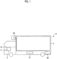
- FIG. 1 is a diagram showing an example of a vehicle including a transport refrigeration system according to the embodiment of the invention.
- a vehicle A is, for example, a truck in which a refrigerator is mounted.
- the vehicle A includes an engine 2 that drives the vehicle A, a cold insulation storage 3 that is mounted in a load compartment, a power generator 10 for a refrigerator that is driven by the engine 2, a power generator 11 for a vehicle that is driven by the engine 2, a battery 20 for a refrigerator, a battery 21 for a vehicle, and a refrigeration unit 30.
- the power generator 11 for a vehicle and the battery 21 for a vehicle are mounted for the purpose of traveling of the vehicle A or supplying power to electric equipment in the vehicle A.
- the power generator 10 for a refrigerator and the battery 20 for a refrigerator are mounted for the purpose of supplying power to the refrigeration unit 30.
- the refrigeration unit 30 operates with power (generated power) generated by the power generator 10 or the generated power of the power generator 10 and power stored in the battery 20 as a power supply, and refrigerates a temperature of the inside of the cold insulation storage 3 to a temperature desired by a user.
- Rated voltages of the power generator 10 and the battery 20 are, for example, 12 V or 24 V.
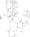
- FIG. 2 is a block diagram showing an example of the transport refrigeration system according to the embodiment of the invention.
- a transport refrigeration system 1 includes the power generator 10, the battery 20, and the refrigeration unit 30.
- the power generator 10 is a constant-voltage power generator that generates power with rotation of the engine 2.
- the power generator 10 is connected to the refrigeration unit 30, and the power generated by the power generator 10 is supplied to the refrigeration unit 30.
- the refrigeration unit 30 refrigerates the cold insulation storage 3 to a desired temperature.
- the refrigeration unit 30 includes a converter 31, an inverter 32, a refrigerator 33, and a controller 40.
- the converter 31 boosts power supplied from the power generator 10.
- the converter 31 outputs the boosted direct-current power to the inverter 32.
- the inverter 32 converts the direct-current power from the converter 31 to three-phase alternating-current power having a frequency according to a refrigeration load and supplies the three-phase alternating-current power to an electric compressor 34 of the refrigerator 33.
- the refrigerator 33 includes a refrigerant circuit that has a condenser, an evaporator, an expansion valve, and the like (not shown) starting with the electric compressor 34.
- a refrigerant is sent out and circulated in the refrigerant circuit by the electric compressor 34.
- the refrigerator 33 refrigerates a space inside the cold insulation storage 3 to a temperature set by the user.
- the controller 40 controls the operation of the refrigerator 33. For example, the controller 40 controls power supplied to the refrigerator 33 through the inverter 32.
- Fig. 3 is a diagram showing an example of the output characteristic of the power generator according to the embodiment of the invention.
- the vertical axis is an output current from the power generator 10
- the horizontal axis is a rotation speed of the power generator 10.
- reference numeral ID indicates the rotation speed (for example, 1200 to 1600 rpm) of the power generator 10 while the vehicle A is idling, and the output current in this case is, for example, about 40 A.
- reference numeral MAX indicates the rotation speed (for example, 5000 to 6000 rpm) of the power generator 10 in a case where a rotation speed of the engine of the vehicle A becomes maximum, and the output current in this case is, for example, about 90 A.
- the magnitude of the current output from the power generator 10 fluctuates two times or more according to a traveling state of the vehicle A. For this reason, there is a possibility that power is short with solely power supplied to the refrigeration unit 30 through power generation of the power generator 10 depending on a target temperature of the cold insulation storage 3 (a load requested by the refrigerator 33) or the traveling state of the vehicle A.
- the transport refrigeration system 1 includes the battery 20 as an auxiliary power supply.
- the battery 20 is a secondary battery that stores power generated by the power generator 10 and supplies the stored power to the refrigeration unit 30.
- the battery 20 is configured to store surplus power of power (load power) consumed by the refrigeration unit 30 out of the direct-current power converted by the converter 31 in response to an instruction of the controller 40.
- the power stored in the battery 20 is configured to be discharged in response to an instruction of the controller 40 and be supplied to the inverter 32.
- the inverter 32 converts direct-current power from the battery 20 to three-phase alternating-current power having a frequency according to the load power requested by the refrigerator 33 and supplies the three-phase alternating-current power to the electric compressor 34.
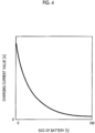
- Fig. 4 is a diagram showing an example of a constant-voltage charging characteristic of the battery according to the embodiment of the invention.
- the vertical axis is a value of the charging current
- the horizontal axis is the SOC of the secondary battery.
- the output of the power generator 10 is a constant voltage (for example, 14 V or 28 V).
- the SOC of the battery 20 in a case where the SOC of the battery 20 is low, a large current flows in the battery 20, and when the SOC becomes high, the current flowing in the battery 20 becomes small.
- the charging current is about 50 A in a case where the SOC is near zero, the charging current decrease to 2 to 3 A in a case where the SOC exceeds 90%.
- a voltage sensor 22 and a current sensor 23 are provided between the battery 20 and the refrigeration unit 30, and a voltage value measured by the voltage sensor 22 and a current value measured by the current sensor 23 are output to the controller 40.
- the battery 20 is provided with a temperature sensor 24, and a temperature measured by the temperature sensor 24 is output to the controller 40.
- the controller 40 calculates the state of charge (SOC: charging rate) of the battery 20 using information regarding the voltage value, the current value, and the temperature acquired from the sensors.
- the controller 40 controls charging and discharging of the battery 20 according to the SOC of the battery 20, the generated power of the power generator 10, and the load power requested by the refrigeration unit 30 while controlling the operation of the refrigerator 33.
- the transport refrigeration system 1 may further include means for charging the battery 20 with power supplied from an external power supply and means for supplying power to the refrigerator.
- the transport refrigeration system 1 further includes a charging device 50, and a charging stand S receives power from an alternating-current power supply V and converts the alternating-current power to direct-current power. Then, in a case where the vehicle A and the charging stand S are connected by a charging cable, the direct-current power is supplied from the charging stand S to the vehicle A side, and the charging device 50 charges the battery 20. With such a configuration, even in a state in which the power generator 10 is not started, it is possible to perform charging to the battery 20 and supply of power to the refrigerator.
- Fig. 5 is a functional block diagram showing an example of the controller in the transport refrigeration system according to the embodiment of the invention.
- the controller 40 is, for example, a computer, such as a microcomputer.
- the controller 40 includes a sensor information acquisition unit 41, a charging rate estimation unit 42, a generated power calculation unit 43, a load power information acquisition unit 44, a charging and discharging control unit 45, a target load setting unit 46, an input unit 47, a refrigerator control unit 48, and a storage unit 49.
- the sensor information acquisition unit 41 acquires the voltage value measured by the voltage sensor 22, the current value measured by the current sensor 23, and the temperature measured by the temperature sensor 24.
- the sensor information acquisition unit 41 acquires a rotation speed from a rotation sensor (not shown) that measures the rotation speed of the power generator 10 (or a rotation sensor that measures the rotation speed of the engine 2).
- the charging rate estimation unit 42 calculates the SOC of the battery 20 based on the voltage value and the current value acquired by the sensor information acquisition unit 41. For example, the charging rate estimation unit 42 calculates the SOC (referred to as an initial SOC) of the battery 20 based on an open circuit voltage (OCV) measured by the voltage sensor 22 in a case where a predetermined time has elapsed after the operation of the refrigerator 33 is stopped, and the battery 20 is in a balanced state, a function indicating the relationship between the open circuit voltage and the SOC of the battery 20, and the like.
- SOCV open circuit voltage
- the charging rate estimation unit 42 integrates the current value (charging current or discharging current) measured by the current sensor 23 to the initial SOC to calculate a current SOC of the battery 20 (current integration method). Since the battery 20 changes in resistance value according to the temperature, temperature correction may be performed on the calculated SOC. For example, the charging rate estimation unit 42 calculates a correction amount according to the temperature measured by the temperature sensor 24 using a predetermined SOC correction value calculation model for defining a correction amount of the SOC according to the temperature of the battery 20 and adds the correction amount to the SOC calculated by the current integration method to calculate the SOC.
- the generated power calculation unit 43 calculates the generated power of the power generator 10. For example, the generated power calculation unit 43 calculates the generated power (W) by obtaining an output current from the rotation speed of the power generator 10 acquired by the sensor information acquisition unit 41 based on a graph illustrated in Fig. 3 and multiplying an output voltage (for example, 24 V) by the output current.
- W generated power
- the load power information acquisition unit 44 acquires information regarding power needed for the operation of the refrigerator 33. For example, the load power information acquisition unit 44 acquires information regarding power consumption from the inverter 32. For example, the load power information acquisition unit 44 acquires a detection value of power consumption of the refrigerator 33.
- the charging and discharging control unit 45 supplies the power stored in the battery 20 to the inverter 32 when the SOC of the battery 20 is equal to a predetermined threshold value (first threshold value) or more.
- first threshold value a predetermined threshold value
- the charging and discharging control unit 45 permits the load power at which the SOC of the battery 20 decreases, and supplies power matching a shortage obtained by subtracting the generated power from the load power from the battery 20 to the inverter 32.
- the charging and discharging control unit 45 stops the supply of the power from the battery 20 to the inverter 32 when the SOC of the battery 20 becomes smaller than a predetermined threshold value (second threshold value). In a situation in which the power stored in the battery 20 is not supplied to the inverter 32, the charging and discharging control unit 45 supplies a surplus of the power generated by the power generator 10 to the battery 20 to charge the battery 20.
- the target load setting unit 46 reduces the load such that the amount of power consumed by the load becomes smaller than the amount of power generated by the power generator 10 when the SOC of the battery 20 becomes smaller than the second threshold value. For example, in a case where the generated power of the power generator 10 is smaller than the load power of the refrigerator 33, the target load setting unit 46 reduces the load power such that the load power of the refrigerator 33 becomes smaller than the generated power of the power generator 10 when the SOC of the battery 20 becomes smaller than the second threshold value.
- the target load setting unit 46 may reduce the load power, for example, such that a predetermined charging current (for example, a charging current according to the SOC based on a charging and discharging current illustrated in Fig. 4 ) flows into the battery 20. Otherwise, for example, the load so far may be maintained for a time as long as possible, and then, the load is decreased sharply, whereby control may be performed such that the amount of power consumption of the load until a predetermined time elapses after the SOC falls below the second threshold value becomes smaller than the amount of power generated by the power generator 10.
- a predetermined charging current for example, a charging current according to the SOC based on a charging and discharging current illustrated in Fig. 4
- the target load setting unit 46 maintains the load as it is.
- the input unit 47 receives an input of information regarding the target temperature of the cold insulation storage 3 or information for instructing the start and stop of the refrigerator 33 from the user.
- the refrigerator control unit 48 controls the operation of the refrigerator 33. For example, in a case where the user performs an operation to start the operation of the refrigerator 33, the refrigerator control unit 48 outputs a control signal for instructing the start to the refrigerator 33 side through the inverter 32. In the refrigerator 33, the electric compressor 34 is started based on the control signal, and the refrigerator 33 starts the operation.
- the refrigerator control unit 48 In a case where the user sets the target temperature of the cold insulation storage 3, the refrigerator control unit 48 generates a control signal according to the target temperature based on a temperature of the inside of the cold insulation storage 3, an ambient temperature, or the like and performs frequency adjustment or the like of the inverter 32 to control an operation state of the refrigerator 33. For example, in a case where the user performs an operation to stop the operation of the refrigerator 33, the refrigerator control unit 48 outputs a control signal for stopping the operation of the refrigerator 33, the refrigerator 33 stops the operation in response to the control signal.
- the storage unit 49 stores various kinds of information, such as the first threshold value and the second threshold value.
- Fig. 6 is a diagram illustrating the charging and discharging control of the transport refrigeration system according to the embodiment of the invention.
- Fig. 6 shows the relationship of a graph ((a) of Fig. 6 ) of a frequency of the power generator 10 in a time series, a graph ((b) of Fig. 6 ) of the load power of the refrigerator 33 in a time series, a graph ((c) of Fig. 6 ) of the charging and discharging current of the battery 20 in a time series, and a graph ((d) of Fig. 6 ) of the SOC of the battery 20 in a time series.
- the horizontal axis of each graph indicates the lapse of time, and the same position on the horizontal axis of each graph indicates the same time.
- the engine 2 of the vehicle A is started.
- the rotation speed of the power generator 10 increases according to the rotation speed of the engine 2 and is maintained at a constant rotation speed in an idling state ((a) of Fig. 6 ).
- the refrigerator 33 is not operated, and accordingly, the load power is zero ((b) of Fig. 6 ). Since the load power is zero, the entire generated power of the power generator 10 for a refrigerator becomes a surplus.
- the charging and discharging control unit 45 assigns the entire generated power of the power generator 10 to the charging of the battery 20 ((c) of Fig. 6 ). In the meantime, the SOC of the battery 20 increases ((d) of Fig. 6 ).
- the rotation speed of the power generator 10 increases and fluctuates for a while ((a) of Fig. 6 ).
- the refrigerator 33 is stopped, and the load power is zero ((b) of Fig. 6 ).
- the charging and discharging control unit 45 assigns the entire generated power of the power generator 10 to the charging of the battery 20 ((c) of Fig. 6 ).
- the SOC of the battery 20 continues to increase ((d) of Fig. 6 ).
- the vehicle A travels at a constant speed.
- the rotation speed of the power generator 10 becomes constant ((a) of Fig. 6 ).
- the refrigerator 33 starts the operation at time T1, and performs the operation with constant load power w1 with respect to the target temperature set by the user ((b) of Fig. 6 ).
- the generated power of the power generator 10 is greater than the load power w1 according to the operation of the refrigerator 33.
- the charging and discharging control unit 45 assigns the surplus (the generated power - the load power w1) of the generated power of the power generator 10 to the charging of the battery 20 ((c) of Fig. 6 ). In the example, it is possible to charge the same power even after time T1.
- the SOC of the battery 20 continues to increase ((d) of Fig. 6 ).
- the SOC of the battery 20 becomes the first threshold value at time T1'.
- the first threshold value is a threshold value of the SOC at which the start of discharging of the battery 20 is permitted in the charging and discharging control of the embodiment.
- the charging and discharging control unit 45 starts the supply of the power from the battery 20 to the refrigeration unit 30.
- the charging and discharging control unit 45 performs control of charging and discharging and control of the load power such that the SOC of the battery 20 does not fall below the second threshold value (for example, the SOC in a case where the refrigerator 33 starts the operation).
- the SOC the SOC at time T1 in a case where the refrigerator 33 starts the operation is the second threshold value.
- the second threshold value is a lowest value of the SOC that the battery 20 can take in the charging and discharging control of the embodiment.
- the SOC of the battery 20 is controlled to be maintained to be the second threshold value or more by the charging and discharging control unit 45.
- a condition may be made that the SOC of the battery 20 becomes equal to the second threshold value or more at the time at which the refrigerator 33 starts the operation.
- the vehicle A reduces the speed, and accordingly, the rotation speed of the power generator 10 also decreases ((a) of Fig. 6 ).
- the refrigerator 33 continues the operation with the same load power w1 ((b) of Fig. 6 ).
- a charging current value flowing in the battery 20 by the charging and discharging control unit 45 starts to decrease ((c) of Fig. 6 ).
- the magnitude of the power generated by the power generator 10 becomes equal to the magnitude of the load power w1 of the refrigerator 33.
- the power generated by the power generator 10 becomes smaller than the load power w1 of the refrigerator 33.
- the charging and discharging control unit 45 stops the charging of the battery 20 at time T4.
- the charging and discharging control unit 45 covers the shortage (the load power w1 - the generated power) with discharging from the battery 20.
- a condition is made that the SOC of the battery 20 becomes equal to the first threshold value or more.
- the condition is satisfied.
- the charging and discharging control unit 45 discharges the battery 20 ((c) of Fig. 6 ), and supplies the power stored in the battery 20 to the refrigerator 33 through the inverter 32. With this, after time T4, the SOC of the battery 20 starts to decrease ((d) of Fig. 6 ). Even though the supply of the power from the battery 20 is started, in a case where the SOC is equal to the second threshold value or more, the load power is maintained at w1 by the target load setting unit 46, and thus, the operation of the refrigerator 33 is not limited. Accordingly, even after time T4, the temperature of the cold insulation storage 3 is controlled to a desired target temperature.
- the vehicle A is stopped in the idling state.
- the rotation speed of the power generator 10 is constant ((a) of Fig. 6 ).
- the charging and discharging control unit 45 continues the discharging of the battery 20 ((c) of Fig. 6 ). Accordingly, the SOC of the battery 20 continues to decrease ((d) of Fig. 6 ).
- the load power is maintained at w1 by the target load setting unit 46 ((b) of Fig. 6 ).
- the temperature of the cold insulation storage 3 is controlled to the target temperature desired by the user.
- the charging and discharging control unit 45 decreases discharge power of the battery 20 ((c) of Fig. 6 ), and performs control such that the total of the generated power of the power generator 10 and the discharge power of the battery 20 becomes equal to the load power w1. Thereafter, at time T7, when the generated power of the power generator 10 becomes equal to the load power w1 of the refrigerator 33 ((a) of Fig. 6 ), the charging and discharging control unit 45 stops the discharging of the battery 20 at time T7 ((c) of Fig. 6 ).
- the charging and discharging control unit 45 supplies the surplus of the generated power of the power generator 10 to the battery 20 to charge the battery 20 ((c) of Fig. 6 ). With this, the SOC of the battery 20 increases.
- the vehicle A further reduces the speed and is brought into the idling state.
- the rotation speed and the generated power of the power generator 10 decrease ((a) of Fig. 6 ).
- the charging and discharging control unit 45 discharges the battery 20 based on a state in which the SOC of the battery 20 is equal to the first threshold value or more and supplements the shortage of the generated power with respect to the load power ((c) of Fig. 6 ).
- the SOC of the battery 20 decreases ((d) of Fig. 6 ).
- the operation of the refrigerator 33 is not limited based on a state in which the SOC of the battery 20 is equal to the second threshold value or more, and the temperature of the cold insulation storage 3 is controlled to the target temperature desired by the user.
- the charging and discharging control unit 45 stops the discharging of the battery 20 at time T9 ((c) of Fig. 6 ). Since the vehicle A continues to be in the idling state even after time T9, the generated power of the power generator 10 still falls below the load power w1. Since the discharging of the battery 20 is stopped based on a state in which the SOC decreases and reaches the second threshold value, it is not possible to maintain the load power w1 as it is. Accordingly, the target load setting unit 46 reduces the load such that the amount of power consumed by the load becomes equal to the amount of power generated by the power generator 10 or less.
- the target load setting unit 46 reduces the load power from w1 to w2 ((b) of Fig. 6 ).
- the load power w2 is set to a value smaller than the generated power of the power generator 10 in a case where the vehicle A is brought into the idling state by the target load setting unit 46.
- the load power is reduced to w2, whereby surplus power remains even though the generated power of the power generator 10 is supplied to the refrigerator 33.
- the charging and discharging control unit 45 supplies the surplus power to the battery 20 to charge the battery 20. With this, the SOC of the battery 20 increases, and then, is recovered to the first threshold value or more.
- the charging and discharging control unit 45 enables the discharging of the battery 20.
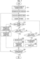
- Fig. 7 is a flowchart showing an example of the charging and discharging control of the transport refrigeration system according to the embodiment of the invention.
- the sensor information acquisition unit 41 acquires the open circuit voltage of the battery 20 measured by the voltage sensor 22 in a state regarded as a no-load state in which the refrigerator 33 is not started.
- the charging rate estimation unit 42 calculates the initial SOC of the battery 20 based on the acquired voltage (Step S11).
- the charging rate estimation unit 42 records the value of the calculated initial SOC in the storage unit 49.
- the refrigerator 33 starts the operation (Step S12).
- the refrigerator control unit 48 drives the electric compressor 34 through the inverter 32.
- the refrigerator control unit 48 controls the frequency of the inverter 32 to operate the refrigerator 33 such that the inside temperature of the cold insulation storage 3 becomes the target temperature set by the user through the input unit 47 according to various operation conditions, such as the inside temperature of the cold insulation storage 3 and an outside temperature.
- the generated power calculation unit 43 calculates the generated power by obtaining the output current from the rotation speed of the power generator 10 acquired by the sensor information acquisition unit 41, for example, based on the graph of Fig. 3 and multiplying the output current by the voltage (Step S13).
- the generated power calculation unit 43 outputs the value of the calculated generated power to the charging and discharging control unit 45.
- the load power information acquisition unit 44 acquires the value of the load power from the inverter 32 (Step S14).
- the load power information acquisition unit 44 outputs the acquired value of the load power to the charging and discharging control unit 45.
- the charging and discharging control unit 45 compares the generated power with the load power (Step S15).
- the charging and discharging control unit 45 supplies the surplus of the generated power obtained by subtracting the load power from the generated power to the battery 20 to charge the battery 20 (Step S16).
- the sensor information acquisition unit 41 acquires the value of the charging current flowing in the battery 20 measured by the current sensor 23.
- the charging rate estimation unit 42 integrates the current value measured by the current sensor 23 and adds the integrated value to the initial SOC to calculate the SOC of the battery 20 during charging (Step S17). In this case, the charging rate estimation unit 42 may correct the SOC based on the internal temperature of the battery 20 measured by the temperature sensor 24.
- the charging rate estimation unit 42 records the value of the calculated SOC in the storage unit 49.
- the charging and discharging control unit 45 determines whether or not the SOC of the battery 20 is equal to the first threshold value or the more (Step S18). In a case where the SOC of the battery 20 is equal to the first threshold value or more (Step S18; Yes), the charging and discharging control unit 45 discharges the battery 20 and supplies the shortage of the power obtained by subtracting the generated power from the load power from the battery 20 to the inverter 32 (Step S19).
- the sensor information acquisition unit 41 acquires the value of the discharging current flowing from the battery 20 measured by the current sensor 23.
- the charging rate estimation unit 42 integrates the current value measured by the current sensor 23 and calculates the SOC of the battery 20 during discharging (Step S20). As in Step S17, the charging rate estimation unit 42 may correct the SOC according to the temperature.
- the charging and discharging control unit 45 determines whether or not the SOC of the battery 20 is equal to the second threshold value or more (Step S21). In a case where the SOC of the battery 20 is equal to the second threshold value or more (Step S21; Yes), the processing after Step S15 is repeated. In a case where the SOC of the battery 20 is less than the second threshold value (Step S21; No), the charging and discharging control unit 45 stops the discharging of the battery 20 (Step S22).
- the target load setting unit 46 reduces the load such that the amount of power consumed by the load becomes smaller than the amount of power generated by the power generator 10 (Step S23). For example, the target load setting unit 46 sets a target value of the load power so as to be equal to the generated power of the power generator 10 or less regardless of the traveling state of the vehicle A and outputs the newly set target value of the load power to the refrigerator control unit 48.
- a reference value of the charging current to the battery 20 may be provided based on the graph of Fig. 4 , and the load power may be set such that the value of the charging current measured by the current sensor 23 becomes equal to the reference value or more.
- the refrigerator control unit 48 decreases the frequency of the inverter 32 according to the load power set by the target load setting unit 46. With this, it is possible to decrease the load power according to the operation of the refrigerator 33.
- the refrigerator control unit 48 determines whether or not to stop the operation of the refrigerator 33 (Step S24). For example, in a case where the user inputs an operation to stop the operation of the refrigerator 33 through the input unit 47, the refrigerator control unit 48 determines to stop the operation of the refrigerator 33. In a case where the operation of the refrigerator 33 is stopped (Step S24; Yes), the flowchart ends.
- Step S24 In a case where the operation of the refrigerator 33 is continued (Step S24; No), the processing from Step S13 is repeated.
- the load In a case where the load is reduced in the processing of Step S23, the load decreases to cause a decrease in rotation speed of the electric compressor 34, and the refrigeration ability for the cold insulation storage 3 decreases; however, in the determination of Step S15, the generated power becomes equal to the load power or more, and the charging and discharging control unit 45 charges the battery 20.
- the SOC of the battery 20 is gradually recovered, and then, when the SOC of the battery 20 becomes equal to the first threshold value or more, the battery 20 is brought into a state capable of being discharged again.
- the excess or shortage of the generated power of the power generator 10 with respect to the load power can be supplemented by the battery 20, for example, it is possible to perform a stable operation of the refrigerator 33 even in a case where fluctuation in generated power of the power generator 10 is large due to sharp change in traveling state of the vehicle A (start or stop, change in traveling speed, or the like). For example, it is possible to exhibit the same refrigeration ability as during traveling even though the vehicle A is stopped in the idling state. In particular, in a state in which the SOC of the battery 20 is high, it is possible to supply the load power that exceeds the generated power of the power generator 10, and to provide a large refrigeration ability.
- the battery 20 In a situation in which the generated power exceeds the load power, the battery 20 is charged with the surplus power and the SOC of the battery 20 is maintained high, whereby it is easy to maintain a state in which power can be supplied from the battery 20, and it is possible to implement a more stable operation.
- the SOC In a scene where the discharging of the battery 20 becomes large, it is possible to maintain the SOC to be equal to the second threshold value or more, and thus, it is possible to restrain early deterioration (sulfation) of the battery 20 due to excessive discharging. Furthermore, it is possible to indirectly ascertain the excess or shortage of the generated power with respect to the load power with the charging and discharging current value to the battery 20.
- the charging and discharging is controlled based on the SOC of the battery 20 or the load requested by the refrigerator 33 is reduced, to this end, there is a need to accurately detect the SOC of the battery 20.
- the charging rate estimation unit 42 of the embodiment it is possible to calculate the SOC of the battery 20 in real time based on the charging and discharging current from the battery 20.
- the transport refrigeration system 1 can be applied to an aircraft or a ship, as well as a vehicle.
- the controller 40 is an example of a control device.
- the vehicle A is an example of a moving body.
- the engine 2 is an example of a power source of the moving body.
- a motor is exemplified.
- the transport refrigeration system having, as a power supply, a power generator that generates power by the drive of the power source of the moving body, and the secondary battery, even in a situation in which the power stored in the secondary battery is used, it is possible to extend the operation time without degrading the refrigeration ability.
Landscapes
- Engineering & Computer Science (AREA)
- Physics & Mathematics (AREA)
- Mechanical Engineering (AREA)
- Thermal Sciences (AREA)
- Chemical & Material Sciences (AREA)
- Combustion & Propulsion (AREA)
- General Engineering & Computer Science (AREA)
- Devices That Are Associated With Refrigeration Equipment (AREA)
- Charge And Discharge Circuits For Batteries Or The Like (AREA)
- Control Of Eletrric Generators (AREA)
Claims (11)
- Steuervorrichtung für einen Kühlschrank (33), die als Stromversorgung einen Leistungsgenerator (10, 11), der von einer Antriebsmaschine oder einem Motor angetrieben wird, welcher eine Stromquelle eines sich bewegenden Körpers ist, und eine Batterie (20, 21) aufweist, die von dem Leistungsgenerator (10, 11) erzeugte Leistung speichert,wobei, wenn die durch den Leistungsgenerator (10, 11) erzeugte Leistung geringer ist als eine von dem Kühlschrank (33) angeforderte Last, die Zufuhr der in der Batterie (20, 21) gespeicherten Leistung zu dem Kühlschrank (33) gestartet wird, wenn der Ladezustand (SOC) der Batterie (20, 21) gleich oder größer als ein erster vorbestimmter Schwellenwert ist, und die Zufuhr von Leistung aus der Batterie (20, 21) zur Abdeckung eines Defizits der vom Leistungsgenerator (10, 11) erzeugten Leistung gegenüber der Last erlaubt ist, bis der Ladezustand (SOC) einen zweiten vorbestimmten Schwellenwert erreicht,wobei, wenn die Leistung von der Batterie (20, 21) dem Kühlschrank (33) zugeführt wird, die vom Kühlschrank (33) angeforderte Last reduziert wird, wenn der Ladezustand (SOC) der Batterie (20, 21) unter den zweiten Schwellenwert fällt, undwobei im Falle einer Lastreduktion die Last so verringert wird, dass die von der Last verbrauchte Leistung geringer ist als die vom Leistungsgenerator (10, 11) erzeugte Leistung, und ein Leistungsüberschuss des Leistungsgenerators (10, 11) dazu verwendet wird, die Batterie (20, 21) zu laden, bis der Ladezustand (SOC) der Batterie (20, 21) wieder den ersten Schwellenwert erreicht, wobei anschließend die vom Kühlschrank (33) angeforderte Last auf ihren ursprünglichen Wert vor der Reduktion zurückgesetzt wird, wenn sich der Ladezustand (SOC) auf den ersten Schwellenwert erholt hat.
- Steuervorrichtung gemäß Anspruch 1, wobei, wenn die Stromversorgung des Kühlschranks (33) durch die Batterie (20, 21) erfolgt, diese Stromversorgung unterbrochen wird, wenn der Ladezustand (SOC) der Batterie (20, 21) unter den zweiten vorbestimmten Schwellenwert fällt.
- Steuervorrichtung gemäß Anspruch 1 oder 2, wobei im Falle einer Lastreduktion die Last so eingestellt wird, dass ein Ladestrom der Batterie (20, 21) einen vorbestimmten Wert erreicht.
- Steuervorrichtung gemäß einem der Ansprüche 1 bis 3, wobei im Falle einer Lastreduktion die Last in Abhängigkeit von der Temperatur eines Kalt-Isolationsspeichers (3), der durch den Kühlschrank (33) gekühlt wird, geregelt wird.
- Steuervorrichtung gemäß einem der Ansprüche 1 bis 4, wobei, wenn keine Stromzufuhr vom der Batterie (20, 21) zum Kühlschrank (33) erfolgt, ein Leistungsüberschuss des Leistungsgenerators (10, 11) dazu verwendet wird, die Batterie (20, 21) zu laden.
- Steuervorrichtung gemäß einem der Ansprüche 1 bis 5, wobei der Ladezustand (SOC) der Batterie (20, 21) auf Grundlage eines Lade- und Entladestroms der Batterie (20, 21) berechnet wird.
- Steuervorrichtung gemäß Anspruch 6, wobei der Ladezustand (SOC) durch Integration des Lade- und Entladestroms unter Bezugnahme auf einen Ladezustand (SOC), der auf einer Leerlaufspannung basiert, berechnet wird, die im Fall eines gestoppten Betriebs des Kühlschranks (33) gemessen wird.
- Steuervorrichtung gemäß Anspruch 6 oder 7, wobei der Ladezustand (SOC) in Abhängigkeit von der Temperatur der Batterie (20, 21) korrigiert wird.
- Transportkühlsystem, umfassend:einen Leistungsgenerator (10, 11), der von einer Antriebsmaschine oder einem Motor angetrieben wird, welcher eine Stromquelle eines sich bewegenden Körpers ist;
eine Batterie (20, 21), die die durch den Leistungsgenerator (10, 11) erzeugte Leistung speichert;einen Kühlschrank (33), der den Leistungsgenerator (10, 11) und die Batterie (20, 21) als Stromversorgung verwendet; undeine Steuervorrichtung gemäß einem der Ansprüche 1 bis 8. - Transportkühlsystem gemäß Anspruch 9, weiterhin umfassend:
Mittel zum Laden der Batterie (20, 21) mit von einer externen Stromversorgung bereitgestelltem Strom und zur Versorgung des Kühlschranks (33) mit Strom. - Steuerverfahren für einen Kühlschrank (33), umfassend den Schritt des Bereitstellens der Steuervorrichtung gemäß Anspruch 1,wobei, wenn die durch den Leistungsgenerator (10, 11) erzeugte Leistung geringer ist als eine vom Kühlschrank (33) angeforderte Last, die Zufuhr der in der Batterie (20, 21) gespeicherten Leistung zum Kühlschrank (33) gestartet wird, wenn der Ladezustand (SOC) der Batterie (20, 21) gleich oder größer als der erste vorbestimmte Schwellenwert ist, und die Zufuhr der Leistung von der Batterie (20, 21) zur Deckung eines Defizits der vom Leistungsgenerator (10, 11) erzeugten Leistung erlaubt ist, bis der Ladezustand (SOC) den zweiten Schwellenwert erreicht,wobei, wenn die Leistung von der Batterie (20, 21) dem Kühlschrank (33) zugeführt wird, die vom Kühlschrank (33) angeforderte Last reduziert wird, wenn der Ladezustand (SOC) der Batterie (20, 21) unter den zweiten Schwellenwert fällt, undwobei im Falle einer Lastreduktion die Last so verringert wird, dass die von der Last verbrauchte Leistung geringer ist als die vom Leistungsgenerator (10, 11) erzeugte Leistung, und ein Leistungsüberschuss des Leistungsgenerators (10, 11) verwendet wird, um die Batterie (20, 21) aufzuladen, bis sich der Ladezustand (SOC) auf den ersten Schwellenwert erholt, woraufhin die vom Kühlschrank (33) angeforderte Last auf ihren ursprünglichen Wert vor der Reduktion zurückgesetzt wird.
Applications Claiming Priority (2)
| Application Number | Priority Date | Filing Date | Title |
|---|---|---|---|
| JP2017152738 | 2017-08-07 | ||
| PCT/JP2018/029288 WO2019031419A1 (ja) | 2017-08-07 | 2018-08-03 | 制御装置、輸送用冷凍システム、制御方法及び充電率算出方法 |
Publications (4)
| Publication Number | Publication Date |
|---|---|
| EP3667207A1 EP3667207A1 (de) | 2020-06-17 |
| EP3667207A4 EP3667207A4 (de) | 2021-05-05 |
| EP3667207C0 EP3667207C0 (de) | 2025-05-14 |
| EP3667207B1 true EP3667207B1 (de) | 2025-05-14 |
Family
ID=65271479
Family Applications (1)
| Application Number | Title | Priority Date | Filing Date |
|---|---|---|---|
| EP18845019.1A Active EP3667207B1 (de) | 2017-08-07 | 2018-08-03 | Steuervorrichtung, transportkühlsystem, und steuerverfahren |
Country Status (3)
| Country | Link |
|---|---|
| EP (1) | EP3667207B1 (de) |
| JP (1) | JP6779382B2 (de) |
| WO (1) | WO2019031419A1 (de) |
Families Citing this family (12)
| Publication number | Priority date | Publication date | Assignee | Title |
|---|---|---|---|---|
| JP7208063B2 (ja) * | 2019-03-05 | 2023-01-18 | 三菱重工サーマルシステムズ株式会社 | 輸送用冷凍機械 |
| JP7208066B2 (ja) * | 2019-03-05 | 2023-01-18 | 三菱重工サーマルシステムズ株式会社 | 輸送用冷凍機械 |
| EP3741605B1 (de) * | 2019-05-24 | 2021-11-24 | Thermo King Corporation | Fahrzeuge für temperaturgesteuerte güter |
| CN112009244A (zh) * | 2019-05-28 | 2020-12-01 | 开利公司 | 运输制冷系统、其控制方法及电动运输车辆 |
| ES2992855T3 (en) | 2019-09-09 | 2024-12-19 | Thermo King Llc | Prioritized power delivery for facilitating transport climate control |
| CN110953775B (zh) * | 2019-11-21 | 2021-08-17 | 海信(山东)冰箱有限公司 | 一种制冷设备和制冷设备控制方法 |
| CN111976488A (zh) * | 2020-08-31 | 2020-11-24 | 安徽江淮汽车集团股份有限公司 | 备用电池控制方法、装置、设备及存储介质 |
| CN116848751A (zh) * | 2021-02-10 | 2023-10-03 | 古河电气工业株式会社 | 维护充电的控制方法及蓄电系统 |
| JP7802025B2 (ja) * | 2021-02-10 | 2026-01-19 | 古河電気工業株式会社 | メンテナンス充電の制御方法及び蓄電システム |
| JP2023129181A (ja) * | 2022-03-04 | 2023-09-14 | 工機ホールディングス株式会社 | 電気機器 |
| US12372580B2 (en) * | 2022-03-28 | 2025-07-29 | Relyion, Inc. | Systems and methods for managing diverse batteries |
| EP4613520A3 (de) * | 2024-03-05 | 2025-10-29 | Carrier Corporation | Stromversorgungsverwaltung in einer transportkühleinheit |
Citations (1)
| Publication number | Priority date | Publication date | Assignee | Title |
|---|---|---|---|---|
| US20100259222A1 (en) * | 2009-03-27 | 2010-10-14 | Tdk-Lambda Corporation | Battery protection circuit, method for protecting battery, power supply device and program |
Family Cites Families (18)
| Publication number | Priority date | Publication date | Assignee | Title |
|---|---|---|---|---|
| JPH0431123A (ja) * | 1990-05-29 | 1992-02-03 | Toshiba Corp | 車両用冷凍装置 |
| US5265435A (en) * | 1992-12-31 | 1993-11-30 | Phyllis M. Morefield | Vehicle refrigeration system |
| JP3029601B2 (ja) * | 1998-04-23 | 2000-04-04 | 松下電器産業株式会社 | 車両用冷凍冷蔵装置 |
| JP2000283622A (ja) * | 1999-03-29 | 2000-10-13 | Toshiba Kyaria Kk | 冷凍車用冷凍装置 |
| JP2001324253A (ja) * | 2000-05-16 | 2001-11-22 | Toshiba Kyaria Kk | 冷凍冷蔵車両 |
| JP2004136699A (ja) * | 2002-10-15 | 2004-05-13 | Denso Corp | ハイブリッド車用空調装置 |
| JP3735337B2 (ja) * | 2002-11-07 | 2006-01-18 | 三菱重工業株式会社 | 車両用冷凍装置およびその制御方法 |
| US7259469B2 (en) * | 2003-07-31 | 2007-08-21 | Scs Frigette Inc. | Vehicle auxiliary power unit, assembly, and related methods |
| JP2005061697A (ja) * | 2003-08-11 | 2005-03-10 | Mitsubishi Heavy Ind Ltd | 輸送用冷凍装置 |
| US7621262B2 (en) * | 2007-05-10 | 2009-11-24 | Ford Global Technologies, Llc | Hybrid thermal energy conversion for HCCI heated intake charge system |
| WO2009029205A1 (en) * | 2007-08-30 | 2009-03-05 | Dimplex Thermal Solutions | Refrigeration power system for a storage compartment in a vehicle |
| US20090120115A1 (en) * | 2007-11-14 | 2009-05-14 | David Hamilton | Diesel truck battery disclosure |
| WO2012138500A1 (en) * | 2011-04-04 | 2012-10-11 | Carrier Corporation | Transport refrigeration system and method for operating |
| JP5880857B2 (ja) * | 2012-05-08 | 2016-03-09 | 株式会社デンソー | 冷凍車温度制御装置 |
| WO2014106225A1 (en) * | 2012-12-31 | 2014-07-03 | Thermo King Corporation | Offset current implementation for battery charger |
| US9951981B2 (en) * | 2014-07-17 | 2018-04-24 | Ford Global Technologies, Llc | System and method for managing lubricant within a vapor compression heat pump |
| JP6370475B2 (ja) | 2015-04-14 | 2018-08-15 | カルソニックカンセイ株式会社 | オルタネータの制御ユニット、オルタネータの駆動制御方法、およびエンジン車両の電源マネージメントシステム |
| JP6291676B2 (ja) | 2017-05-16 | 2018-03-14 | 東京エレクトロン株式会社 | 薬液排出機構、液処理装置、薬液排出方法、記憶媒体 |
-
2018
- 2018-08-03 JP JP2019535627A patent/JP6779382B2/ja active Active
- 2018-08-03 EP EP18845019.1A patent/EP3667207B1/de active Active
- 2018-08-03 WO PCT/JP2018/029288 patent/WO2019031419A1/ja not_active Ceased
Patent Citations (1)
| Publication number | Priority date | Publication date | Assignee | Title |
|---|---|---|---|---|
| US20100259222A1 (en) * | 2009-03-27 | 2010-10-14 | Tdk-Lambda Corporation | Battery protection circuit, method for protecting battery, power supply device and program |
Also Published As
| Publication number | Publication date |
|---|---|
| EP3667207C0 (de) | 2025-05-14 |
| EP3667207A1 (de) | 2020-06-17 |
| EP3667207A4 (de) | 2021-05-05 |
| JP6779382B2 (ja) | 2020-11-04 |
| JPWO2019031419A1 (ja) | 2020-04-23 |
| WO2019031419A1 (ja) | 2019-02-14 |
Similar Documents
| Publication | Publication Date | Title |
|---|---|---|
| EP3667207B1 (de) | Steuervorrichtung, transportkühlsystem, und steuerverfahren | |
| US7196492B2 (en) | Power supply apparatus including fuel cell and capacitor, and operation method thereof | |
| US7911184B2 (en) | Battery charging time optimization system | |
| EP2689944B1 (de) | Kühlsystem für Transportzwecke | |
| US9562715B2 (en) | Power regulation system for a mobile environment-controlled unit and method of controlling the same | |
| US8154252B2 (en) | System and method for monitoring the state of charge of a battery | |
| US20150121923A1 (en) | Transport refrigeration system having electric fans | |
| US9174542B2 (en) | Power supply device for vehicle | |
| CN102369622A (zh) | 燃料电池系统、用于燃料电池系统的控制方法以及配备有燃料电池系统的车辆 | |
| US9694692B2 (en) | Vehicle controlling system | |
| US11597257B2 (en) | Transportation refrigeration system, for transportation vehicle, control method thereof and electric transportation vehicle | |
| JP7311279B2 (ja) | 輸送用冷凍機械 | |
| US20200353797A1 (en) | Architecture and method for battery charger with dual output voltage and charge management for a transport refrigeration unit | |
| JP5417876B2 (ja) | 冷凍装置 | |
| EP4219199A1 (de) | Stromsystem für eine transportkühleinheit | |
| JP7027802B2 (ja) | 燃料電池車の電圧制御装置 | |
| JP4127078B2 (ja) | 車両用電源制御装置 | |
| US12184115B2 (en) | System and method for managing electrical power drawn from a vehicle alternator | |
| US20050151508A1 (en) | Battery isolator | |
| KR101186467B1 (ko) | 냉동, 냉장 및 온장 식품 운반용 차량의 전력 제어장치 및 방법 | |
| GB2631445A (en) | Control system for electrical energy source management | |
| JP7208066B2 (ja) | 輸送用冷凍機械 | |
| JP2025150601A (ja) | ソーラー充電システム | |
| JP2021064511A (ja) | 燃料電池システム |
Legal Events
| Date | Code | Title | Description |
|---|---|---|---|
| STAA | Information on the status of an ep patent application or granted ep patent |
Free format text: STATUS: THE INTERNATIONAL PUBLICATION HAS BEEN MADE |
|
| PUAI | Public reference made under article 153(3) epc to a published international application that has entered the european phase |
Free format text: ORIGINAL CODE: 0009012 |
|
| STAA | Information on the status of an ep patent application or granted ep patent |
Free format text: STATUS: REQUEST FOR EXAMINATION WAS MADE |
|
| 17P | Request for examination filed |
Effective date: 20191216 |
|
| AK | Designated contracting states |
Kind code of ref document: A1 Designated state(s): AL AT BE BG CH CY CZ DE DK EE ES FI FR GB GR HR HU IE IS IT LI LT LU LV MC MK MT NL NO PL PT RO RS SE SI SK SM TR |
|
| AX | Request for extension of the european patent |
Extension state: BA ME |
|
| DAV | Request for validation of the european patent (deleted) | ||
| DAX | Request for extension of the european patent (deleted) | ||
| A4 | Supplementary search report drawn up and despatched |
Effective date: 20210406 |
|
| RIC1 | Information provided on ipc code assigned before grant |
Ipc: F25D 11/00 20060101AFI20210329BHEP Ipc: B60H 1/32 20060101ALI20210329BHEP Ipc: B60P 3/20 20060101ALI20210329BHEP Ipc: B60R 16/02 20060101ALI20210329BHEP Ipc: B60R 16/04 20060101ALI20210329BHEP |
|
| STAA | Information on the status of an ep patent application or granted ep patent |
Free format text: STATUS: EXAMINATION IS IN PROGRESS |
|
| 17Q | First examination report despatched |
Effective date: 20230206 |
|
| GRAP | Despatch of communication of intention to grant a patent |
Free format text: ORIGINAL CODE: EPIDOSNIGR1 |
|
| STAA | Information on the status of an ep patent application or granted ep patent |
Free format text: STATUS: GRANT OF PATENT IS INTENDED |
|
| INTG | Intention to grant announced |
Effective date: 20241203 |
|
| RIN1 | Information on inventor provided before grant (corrected) |
Inventor name: MIZUNO, YUICHIRO Inventor name: KAI, MASAKAZU Inventor name: NARITA, SADAHARU |
|
| GRAS | Grant fee paid |
Free format text: ORIGINAL CODE: EPIDOSNIGR3 |
|
| GRAA | (expected) grant |
Free format text: ORIGINAL CODE: 0009210 |
|
| STAA | Information on the status of an ep patent application or granted ep patent |
Free format text: STATUS: THE PATENT HAS BEEN GRANTED |
|
| AK | Designated contracting states |
Kind code of ref document: B1 Designated state(s): AL AT BE BG CH CY CZ DE DK EE ES FI FR GB GR HR HU IE IS IT LI LT LU LV MC MK MT NL NO PL PT RO RS SE SI SK SM TR |
|
| RAP3 | Party data changed (applicant data changed or rights of an application transferred) |
Owner name: MITSUBISHI HEAVY INDUSTRIES THERMAL SYSTEMS, LTD. |
|
| REG | Reference to a national code |
Ref country code: GB Ref legal event code: FG4D |
|
| REG | Reference to a national code |
Ref country code: CH Ref legal event code: EP |
|
| REG | Reference to a national code |
Ref country code: IE Ref legal event code: FG4D |
|
| U01 | Request for unitary effect filed |
Effective date: 20250514 |
|
| U07 | Unitary effect registered |
Designated state(s): AT BE BG DE DK EE FI FR IT LT LU LV MT NL PT RO SE SI Effective date: 20250520 |
|
| U20 | Renewal fee for the european patent with unitary effect paid |
Year of fee payment: 8 Effective date: 20250831 |
|
| PG25 | Lapsed in a contracting state [announced via postgrant information from national office to epo] |
Ref country code: ES Free format text: LAPSE BECAUSE OF FAILURE TO SUBMIT A TRANSLATION OF THE DESCRIPTION OR TO PAY THE FEE WITHIN THE PRESCRIBED TIME-LIMIT Effective date: 20250514 |
|
| PG25 | Lapsed in a contracting state [announced via postgrant information from national office to epo] |
Ref country code: NO Free format text: LAPSE BECAUSE OF FAILURE TO SUBMIT A TRANSLATION OF THE DESCRIPTION OR TO PAY THE FEE WITHIN THE PRESCRIBED TIME-LIMIT Effective date: 20250814 Ref country code: GR Free format text: LAPSE BECAUSE OF FAILURE TO SUBMIT A TRANSLATION OF THE DESCRIPTION OR TO PAY THE FEE WITHIN THE PRESCRIBED TIME-LIMIT Effective date: 20250815 |
|
| PG25 | Lapsed in a contracting state [announced via postgrant information from national office to epo] |
Ref country code: PL Free format text: LAPSE BECAUSE OF FAILURE TO SUBMIT A TRANSLATION OF THE DESCRIPTION OR TO PAY THE FEE WITHIN THE PRESCRIBED TIME-LIMIT Effective date: 20250514 |
|
| PG25 | Lapsed in a contracting state [announced via postgrant information from national office to epo] |
Ref country code: HR Free format text: LAPSE BECAUSE OF FAILURE TO SUBMIT A TRANSLATION OF THE DESCRIPTION OR TO PAY THE FEE WITHIN THE PRESCRIBED TIME-LIMIT Effective date: 20250514 |
|
| PG25 | Lapsed in a contracting state [announced via postgrant information from national office to epo] |
Ref country code: RS Free format text: LAPSE BECAUSE OF FAILURE TO SUBMIT A TRANSLATION OF THE DESCRIPTION OR TO PAY THE FEE WITHIN THE PRESCRIBED TIME-LIMIT Effective date: 20250814 |
|
| PG25 | Lapsed in a contracting state [announced via postgrant information from national office to epo] |
Ref country code: IS Free format text: LAPSE BECAUSE OF FAILURE TO SUBMIT A TRANSLATION OF THE DESCRIPTION OR TO PAY THE FEE WITHIN THE PRESCRIBED TIME-LIMIT Effective date: 20250914 |
|
| PG25 | Lapsed in a contracting state [announced via postgrant information from national office to epo] |
Ref country code: SM Free format text: LAPSE BECAUSE OF FAILURE TO SUBMIT A TRANSLATION OF THE DESCRIPTION OR TO PAY THE FEE WITHIN THE PRESCRIBED TIME-LIMIT Effective date: 20250514 |
|
| PG25 | Lapsed in a contracting state [announced via postgrant information from national office to epo] |
Ref country code: CZ Free format text: LAPSE BECAUSE OF FAILURE TO SUBMIT A TRANSLATION OF THE DESCRIPTION OR TO PAY THE FEE WITHIN THE PRESCRIBED TIME-LIMIT Effective date: 20250514 |
|
| PG25 | Lapsed in a contracting state [announced via postgrant information from national office to epo] |
Ref country code: SK Free format text: LAPSE BECAUSE OF FAILURE TO SUBMIT A TRANSLATION OF THE DESCRIPTION OR TO PAY THE FEE WITHIN THE PRESCRIBED TIME-LIMIT Effective date: 20250514 |
|
| PLBE | No opposition filed within time limit |
Free format text: ORIGINAL CODE: 0009261 |
|
| STAA | Information on the status of an ep patent application or granted ep patent |
Free format text: STATUS: NO OPPOSITION FILED WITHIN TIME LIMIT |
|
| REG | Reference to a national code |
Ref country code: CH Ref legal event code: H13 Free format text: ST27 STATUS EVENT CODE: U-0-0-H10-H13 (AS PROVIDED BY THE NATIONAL OFFICE) Effective date: 20260324 |
|
| REG | Reference to a national code |
Ref country code: CH Ref legal event code: L10 Free format text: ST27 STATUS EVENT CODE: U-0-0-L10-L00 (AS PROVIDED BY THE NATIONAL OFFICE) Effective date: 20260325 |
|
| PG25 | Lapsed in a contracting state [announced via postgrant information from national office to epo] |
Ref country code: MC Free format text: LAPSE BECAUSE OF FAILURE TO SUBMIT A TRANSLATION OF THE DESCRIPTION OR TO PAY THE FEE WITHIN THE PRESCRIBED TIME-LIMIT Effective date: 20250514 |
|
| 26N | No opposition filed |
Effective date: 20260217 |
|
| PG25 | Lapsed in a contracting state [announced via postgrant information from national office to epo] |
Ref country code: CH Free format text: LAPSE BECAUSE OF NON-PAYMENT OF DUE FEES Effective date: 20250831 |