EP3667348B1 - Dispositif et procédé de limitation b1 - Google Patents
Dispositif et procédé de limitation b1 Download PDFInfo
- Publication number
- EP3667348B1 EP3667348B1 EP18212446.1A EP18212446A EP3667348B1 EP 3667348 B1 EP3667348 B1 EP 3667348B1 EP 18212446 A EP18212446 A EP 18212446A EP 3667348 B1 EP3667348 B1 EP 3667348B1
- Authority
- EP
- European Patent Office
- Prior art keywords
- voltage sensor
- magnetic resonance
- signal
- feed line
- resonance tomography
- Prior art date
- Legal status (The legal status is an assumption and is not a legal conclusion. Google has not performed a legal analysis and makes no representation as to the accuracy of the status listed.)
- Active
Links
Images
Classifications
-
- G—PHYSICS
- G01—MEASURING; TESTING
- G01R—MEASURING ELECTRIC VARIABLES; MEASURING MAGNETIC VARIABLES
- G01R33/00—Arrangements or instruments for measuring magnetic variables
- G01R33/20—Arrangements or instruments for measuring magnetic variables involving magnetic resonance
- G01R33/28—Details of apparatus provided for in groups G01R33/44 - G01R33/64
- G01R33/32—Excitation or detection systems, e.g. using radio frequency signals
- G01R33/36—Electrical details, e.g. matching or coupling of the coil to the receiver
- G01R33/3628—Tuning/matching of the transmit/receive coil
-
- G—PHYSICS
- G01—MEASURING; TESTING
- G01R—MEASURING ELECTRIC VARIABLES; MEASURING MAGNETIC VARIABLES
- G01R33/00—Arrangements or instruments for measuring magnetic variables
- G01R33/20—Arrangements or instruments for measuring magnetic variables involving magnetic resonance
- G01R33/28—Details of apparatus provided for in groups G01R33/44 - G01R33/64
- G01R33/288—Provisions within MR facilities for enhancing safety during MR, e.g. reduction of the specific absorption rate [SAR], detection of ferromagnetic objects in the scanner room
-
- G—PHYSICS
- G01—MEASURING; TESTING
- G01R—MEASURING ELECTRIC VARIABLES; MEASURING MAGNETIC VARIABLES
- G01R33/00—Arrangements or instruments for measuring magnetic variables
- G01R33/20—Arrangements or instruments for measuring magnetic variables involving magnetic resonance
- G01R33/28—Details of apparatus provided for in groups G01R33/44 - G01R33/64
- G01R33/32—Excitation or detection systems, e.g. using radio frequency signals
- G01R33/36—Electrical details, e.g. matching or coupling of the coil to the receiver
-
- G—PHYSICS
- G01—MEASURING; TESTING
- G01R—MEASURING ELECTRIC VARIABLES; MEASURING MAGNETIC VARIABLES
- G01R33/00—Arrangements or instruments for measuring magnetic variables
- G01R33/20—Arrangements or instruments for measuring magnetic variables involving magnetic resonance
- G01R33/44—Arrangements or instruments for measuring magnetic variables involving magnetic resonance using nuclear magnetic resonance [NMR]
- G01R33/48—NMR imaging systems
-
- G—PHYSICS
- G01—MEASURING; TESTING
- G01R—MEASURING ELECTRIC VARIABLES; MEASURING MAGNETIC VARIABLES
- G01R33/00—Arrangements or instruments for measuring magnetic variables
- G01R33/20—Arrangements or instruments for measuring magnetic variables involving magnetic resonance
- G01R33/44—Arrangements or instruments for measuring magnetic variables involving magnetic resonance using nuclear magnetic resonance [NMR]
- G01R33/48—NMR imaging systems
- G01R33/54—Signal processing systems, e.g. using pulse sequences ; Generation or control of pulse sequences; Operator console
- G01R33/543—Control of the operation of the MR system, e.g. setting of acquisition parameters prior to or during MR data acquisition, dynamic shimming, use of one or more scout images for scan plane prescription
Definitions
- the invention relates to a device for limiting the B1 field and a method for operating a magnetic resonance tomograph using this device.
- the magnetic resonance tomograph has a transmitter for generating excitation pulses, an antenna for emitting the excitation pulses, a feed line between the transmitter and a feed point of the antenna, and a voltage sensor.
- Magnetic resonance tomographs are imaging devices which, in order to image an examination object, align nuclear spins of the examination object with a strong external magnetic field and excite them to precess around this alignment by means of an alternating magnetic field. The precession or return of the spins from this excited state to a lower-energy state in turn generates an alternating magnetic field in response, which is received by antennas.
- a spatial coding is impressed on the signals, which subsequently enables the received signal to be assigned to a volume element.
- the signal received is then evaluated and a three-dimensional imaging representation of the examination object is provided.
- the strongest possible B1 alternating field from the excitation pulses is desired.
- there are limit values for the B1 alternating field which, due to regulatory provisions, must not be exceeded in order not to endanger the patient through overheating due to absorbed power and/or induced voltages and currents.
- the achievable field strength depends heavily on the tuning and quality of the antenna, which in turn can change due to the size, weight and position of the patient, for example.
- a magnetic resonance tomograph is known.
- a transmitting device is connected to a transmitting antenna via a coaxial cable.
- the distance between the transmission antenna and a sensor on the coaxial cable is n/2 times a wavelength of the radio frequency to be transmitted in the coaxial cable, where n is a natural number.
- the document DE 10 2008 063630 A1 describes a method for monitoring a high-frequency transmission device of a magnetic resonance tomography system with a transmission antenna system with a plurality of transmission channels.
- Transmission amplitude vectors which represent the high-frequency voltage amplitudes on the individual transmission channels, are determined as a function of time.
- high-frequency power values absorbed in the examination object are determined at specific transmission times and a number of control values are formed based on a large number of the determined high-frequency power values.
- the function of the high-frequency transmission device is restricted if a control value exceeds a predetermined limit control value.
- the task is therefore to make image acquisition with magnetic resonance tomographs better and more reliable.
- the object is achieved by a magnetic resonance tomograph according to claim 1 according to the invention and the method according to the invention for operating a magnetic resonance tomograph according to claim 9 .
- the magnetic resonance tomograph according to the invention has a transmitter for generating excitation pulses.
- the frequency of The excitation pulse is the Larmor frequency, which has a nuclear spin of an element to be examined, usually hydrogen, in the static B0 field of a field magnet of the magnetic resonance tomograph. Due to the gradient fields for spatial resolution, the frequency of the excitation pulse can also vary around the Larmor frequency at field B0.
- a lambda wavelength is assigned to the excitation pulse.
- the wavelength lambda is the wavelength which the electromagnetic signal generated by the transmitter as an excitation pulse has and which is obtained by dividing the propagation speed c in the vacuum by the frequency.
- the magnetic resonance tomograph also has an antenna for emitting the excitation pulses and a feed line between the transmitter and a feed point of the antenna.
- the electrical line that conducts the excitation pulse from the transmitter to the antenna is referred to as the feed line.
- the feed line can be a coaxial line or a ridge line, for example.
- the feed line can also have other elements, such as a power divider, to distribute the signal from a transmitter to a number of antennas.
- the wavelength lambda on the feed line is shortened by 10%, 20% or more compared to a wavelength of an electromagnetic wave in vacuum with the Larmor frequency.
- the antenna is, for example, a body coil, which is also referred to as a "birdcage" antenna.
- the feed point is the transfer point from the feed line to the antenna, which is on the end ring in a birdcage antenna.
- the transmitter must be designed to generate excitation pulses at the Larmor frequency with a power of a few hundred watts up to kilowatts.
- the magnetic resonance tomograph also has a voltage sensor.
- the voltage sensor is on the feed line located at an effective distance of a multiple of half wavelength lambda equal to n*lambda/2 from the feed point, where n is a natural number.
- the effective distance n*Lambda/2 is a geometric distance along the feed line, starting from the feed point, for which there is a phase shift of the electromagnetic wave between the voltage sensor and the feed point of n*180 degrees or n*Pi, corresponding to a distance in a vacuum of length n*Lambda/2.
- the effective distance can be extended compared to the geometric length due to the speed of propagation, which is reduced compared to the speed of light in a vacuum due to the dielectric and geometry.
- the matching circuit provided according to the invention with one or more matching elements also results in a phase shift that changes the effective distance.
- the real position of the voltage sensor can deviate from the calculated position by more than 1%, 2%, 5% or 10% within a tolerance, for example the Larmor frequency due to a static magnetic field B0 that varies from device to device.
- the voltage sensor delivers a signal that depends on the electrical potential on the feed line at the location of the voltage sensor.
- the voltage sensor uses the effective distance according to the invention to supply a measured value which reflects the voltage at the feed point of the antenna.
- the generated magnetic field B1 is essentially proportional to the current in the antenna.
- the voltage that is recorded via the voltage sensor for the feed point is in turn also for resonant antennas, in which the oscillating current in the antenna is significantly larger than that supplied via the feed line, essentially proportional to the current in the antenna and thus also to the B1 field of the antenna.
- the voltage detected by the voltage sensor is a good measure of the B1 field of the antenna.
- the feed line of the magnetic resonance tomograph according to the invention has a matching circuit between the voltage sensor and the feed point for matching the impedance of the transmitting antenna to the feed line.
- the matching circuit itself causes a phase shift due to these components.
- the feed line is designed in such a way that the cumulative phase shift between the voltage sensor and feed point caused by the length of the feed line between the voltage sensor and the feed point and by the matching circuit itself corresponds to a phase shift for the excitation pulse caused by a distance in the vacuum of length n*lambda/2, so that a reading from the voltage sensor reflects the voltage at the feed point of the antenna.
- the matching circuit has one, two or more capacitances and/or inductances.
- a pi element is often used as a matching circuit for antennas.
- a matching circuit with capacitances and, in particular, ferrite-free inductors offers a simple and safe way of matching the transmitter to the antenna in the vicinity of a magnetic resonance tomograph.
- the voltage sensor has a capacitive coupling.
- capacitive coupling refers to coupling that is based on the electric field and potential and not on the flowing currents, in particular not on induction.
- the capacitive coupling is also non-conductive for frequencies approaching zero, i.e. the voltage sensor is isolated from the feed line for DC voltages.
- the capacitive coupling in particular in connection with a high-impedance voltage sensor, minimizes the sensor's reaction to the feed line and at the same time provides insulation with regard to the applied DC voltages.
- the voltage sensor is designed to output a signal that is proportional to the square of the voltage on the feed line.
- a diode probe is conceivable.
- the square-law characteristic allows a power at the feed point to be inferred directly from the signal from the voltage sensor, and thus directly the squared value of the B1 field and thus a value that is relevant and proportional to the SAR exposure.
- the magnetic resonance tomograph has a monitoring circuit.
- the monitoring circuit is in signal communication with the voltage sensor to receive a signal dependent on the voltage sensed by the voltage sensor.
- the monitoring circuit is still in signal communication with the transmitter.
- the monitoring circuit and the transmitter are designed in such a way that the monitoring circuit can influence an output power of the transmitter via the signal connection.
- the monitoring circuit is designed to interrupt transmission by the transmitter when a signal from the voltage sensor exceeds a predetermined threshold. For example, the signal from the voltage sensor in the monitoring circuit can be compared with a predetermined threshold value by means of a comparator. If the signal becomes too large and thus too much power radiated into the patient, the monitoring circuit can reduce an input signal of the transmitter via the signal connection, for example via an adjustable resistor, or switch it off via a switch.
- the voltage sensor and the monitoring circuit advantageously allow the transmission power to be checked in real time.
- the magnetic resonance tomograph has a tuning element.
- the tuning element can be a variable capacitance or inductance, for example.
- the tuning element is electrically connected to the feed line at the location of the voltage sensor.
- the tuning element acts in the same way as a similar tuning element at the feed point. At the same time, however, it is advantageously at a distance from the immediate vicinity of the image acquisition, so that, for example, materials can be used that affect the static magnetic field directly at the image acquisition site and would interfere with the image acquisition. For example, motor-driven tuning elements can also be used.
- the transmitter has a control input.
- An input to which a signal can be applied is regarded as a control input, with the output signal of the transmitter then depending on this signal, for example the voltage and phase of the output signal.
- the voltage sensor is in signal connection with the control input.
- the magnetic resonance tomograph has a second sensor.
- the second sensor is designed to deliver a signal depending on an amplitude and phase as well as the direction of propagation of a high-frequency signal on the feed line.
- the second sensor can be a directional coupler.
- the second sensor also allows a direction-dependent power component to be detected, so that reflected power can also be determined. In this way, the power of the B1 field generated by the transmitter can be recorded even more precisely.
- the second sensor allows a function check of the tension sensor.
- the method according to the invention for operating the magnetic resonance tomograph according to the invention has the step of acquiring a signal from the voltage sensor with the monitoring circuit.
- the signal is compared with a predetermined threshold value by the monitoring circuit.
- the monitoring circuit emits a warning signal when the predetermined threshold value is exceeded.
- the warning signal can be fed to an operator of the magnetic resonance tomograph, for example via a display or acoustically, or it can be output to a controller of the magnetic resonance tomograph or the transmitter in order to carry out countermeasures. It is also conceivable that the warning signal is fed to the transmitter in one step and leads to an interruption or limitation of the transmission signal.
- the method according to the invention advantageously allows the patient's SAR exposure to be monitored and, if necessary, by means of the voltage proportional to the B1 field to ensure the safety of the patient if the limit values are exceeded.
- the method also has the step of determining a relationship between the signal of the voltage sensor and a B1 field strength for calibration. It is conceivable, for example, to determine the field strength B1 achieved by an excitation pulse using a field probe or a phantom. If the voltage at the voltage sensor is also recorded during the excitation pulse, a proportionality factor from B1 to the measured voltage can be determined for calibration.
- the calibration allows a direct conclusion from the measured voltage at the voltage sensor to the generated B1 field strength.
- the magnetic field can be monitored in real time using the voltage and the pulse can be interrupted immediately if limit values are exceeded in order to ensure the safety of the patient.
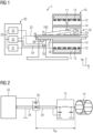
- FIG. 1 shows a schematic representation of an embodiment of a magnetic resonance tomograph 1.
- the magnet unit 10 has a field magnet 11 that generates a static magnetic field B0 for aligning nuclear spins of samples or of the patient 100 in a recording area.
- the recording area is characterized by an extremely homogeneous static magnetic field B0, with the homogeneity particularly affecting the magnetic field strength or the amount.
- the receiving area is almost spherical and is arranged in a patient tunnel 16 which extends through the magnet unit 10 in a longitudinal direction 2 .
- a patient bed 30 can be moved in the patient tunnel 16 by the traversing unit 36 .
- the field magnet 11 is usually a superconducting magnet that can provide magnetic fields with a magnetic flux density of up to 3T, and even more in the case of the latest devices. For lower field strengths, however, permanent magnets or electromagnets with normally conducting coils can also be used.
- the magnet unit 10 has gradient coils 12 which are designed to superimpose variable magnetic fields in three spatial directions on the magnetic field B0 for spatial differentiation of the recorded imaging regions in the examination volume.
- the gradient coils 12 are usually coils made from normally conducting wires, which can generate mutually orthogonal fields in the examination volume.
- the magnet unit 10 also has a body coil 14 which is designed to emit a high-frequency signal supplied via a feed line 34 into the examination volume and to receive resonance signals emitted by the patient 100 and emit them via a signal line.
- the feed line 34 is electrically connected to the body coil 14 at a feed point.
- a voltage sensor 35 is at a distance d along the feed line from the feed point electrically connected to the feed line 34 and is in signal connection with the radio frequency unit 22.
- a control unit 20 supplies the magnet unit 10 with the various signals for the gradient coils 12 and the body coil 14 and evaluates the received signals.
- control unit 20 has a gradient control 21, which is designed to supply the gradient coils 12 with variable currents via supply lines, which provide the desired gradient fields in the examination volume in a time-coordinated manner.
- control unit 20 has a high-frequency unit 22 which is designed to generate a high-frequency pulse with a predetermined time profile, amplitude and spectral power distribution for exciting a magnetic resonance of the nuclear spins in the patient 100 .
- Pulse powers in the kilowatt range can be achieved.
- the excitation pulses can be radiated into the patient 100 via the body coil 14 or via a local transmitting antenna.
- a controller 23 communicates with the gradient controller 21 and the radio-frequency unit 22 via a signal bus 25.
- a local coil 50 is arranged on the patient 100 and is connected to the high-frequency unit 22 and its receiver via a connecting line 33 .
- the high-frequency unit 22 as a transmitter outputs the excitation pulse to a feed line 34 that connects the high-frequency unit 22 to the body coil 14 as an antenna.
- a local coil 50 is also conceivable as an antenna.
- the feed line 34 is a line that transmits the high-frequency signal or the excitation pulse from the high-frequency unit 22 to the antenna 2 represented by the body coil 14.
- a coaxial line is usually used here because of its shielding outer conductor. In principle, however, other high-frequency lines such as ridge lines are also conceivable as the feed line 34 .
- the feed line 34 also comprises a matching circuit 15 within the meaning of the invention, which carries out an impedance matching between an impedance of the feed line 34 and the body coil 14 .
- the matching circuit 15 can be implemented by a PI element, but also by individual or multiple capacitances and/or inductances.
- other elements such as a line distributor, to be provided in the feed line 34 between the transmitter and the voltage sensor 35 in order to distribute the power of the transmitter to a plurality of feed lines 34 and antennas.
- the voltage sensor 35 is arranged at a distance d from the feed point, measured along the extent of the feed line 34 .
- the phase shift caused by the feed line 34 between the voltage sensor 35 and the feed point for a high-frequency signal with the Larmor frequency f L corresponds to a value of n*Pi or n*180 degrees with n being a natural number greater than zero.
- the voltage sensor 35 is arranged on the feed line 34 at a distance d eff from the feed point of the body coil 14 so that there is a phase shift of lambda/2 between the voltage sensor 35 and the feed point of the antenna or body coil 14 . Because of this phase shift, a voltage value results at the location of the voltage sensor 35 for an excitation pulse with the Larmor frequency or wavelength lambda, which corresponds to the voltage at the feed point.
- the generated magnetic field B1 is essentially proportional to the current in the antenna.
- the voltage sensed across the feed point voltage sensor 35 is proportional to the current in the antenna and therefore also to the B1 field of the antenna. This essentially also applies in the event that the current in the antenna is greater than the current supplied via the feed line due to resonance. At least for typical resonant antennas with qualities greater than 50, this is fulfilled to a good approximation. Therefore, the voltage at the voltage sensor 35 with a proportionality factor obtained, for example, by a calibration is a good measure for the B1 field generated by the antenna.
- the voltage sensor 35 is preferably capacitively coupled to the feed line 34 in order to influence the transmitter signal as little as possible.
- a high impedance of the voltage sensor is advantageous here. In principle, however, an ohmic coupling with a high impedance would also be conceivable, in which case there would be no galvanic isolation.
- sensor signals are also conceivable, which are linked by the monitoring circuit with the signal of the voltage sensor 35 in order to detect a malfunction of a sensor.
- Directional couplers are conceivable, for example, in the feed line 34, which return a reflected power or a power output to the antenna to the high-frequency unit 22 by means of a sensor signal, for example to have the matching adjusted by the matching circuit 15 or to protect the output stages by reducing the output power of the High-frequency unit 22 is reduced.
- the monitoring circuit can carry out a plausibility check, for example. If one of the sensor values is constantly zero while the other changes with the activation of the transmitter, a malfunction of a sensor can be concluded and the monitoring circuit can interrupt the transmission of the excitation pulse for safety reasons.
- a signal from the tension sensor 35 is detected with the monitoring circuit.
- the signal can be detected analogously by the voltage sensor 35 and forwarded to the monitoring circuit via a signal line.
- digitization with an A/D converter can also be carried out, for example, and the digital voltage signal can be forwarded via a bus or a line.
- the monitoring circuit compares the detected voltage signal from the voltage sensor 35 with a predetermined threshold value.
- the predetermined threshold value can be specified, for example, by regulatory provisions for SAR exposure. In the case of an analog signal, this can be done, for example, by a simple comparator, in digital form by hard-wired logic to increase reliability, or by programmed logic in a controller of the monitoring circuit.
- the monitoring circuit itself can also be implemented by a program in the controller 23 of the magnetic resonance tomograph.
- the monitoring circuit emits a warning signal if the predetermined threshold value is exceeded.
- the warning signal can then be output to an operator, for example acoustically or via a display.
- warning signal it is also conceivable for the warning signal to be forwarded to the controller 23, which then interrupts the transmission of the excitation pulse. This allows a particularly quick reaction to exceeding a SAR limit value.
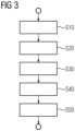
- a relation between the signal of the voltage sensor and a B1 field strength is determined in a step S10 for calibration. It is conceivable, for example, that when a magnetic resonance tomograph 1 is installed, a field probe is connected to the controller 23, which delivers a measured value for a B1 field. By simultaneously detecting the signal from the voltage sensor 35 and the signal from the field probe, a proportionality factor can be determined between the B1 field by an excitation pulse and the signal from the voltage sensor 35 by means of quotient formation, so that a detected voltage value from the voltage sensor 35 can be converted to a value of the B1 field can be closed.
Landscapes
- Physics & Mathematics (AREA)
- Condensed Matter Physics & Semiconductors (AREA)
- General Physics & Mathematics (AREA)
- High Energy & Nuclear Physics (AREA)
- Engineering & Computer Science (AREA)
- Signal Processing (AREA)
- Magnetic Resonance Imaging Apparatus (AREA)
Claims (10)
- Tomodensitomètre à résonnance magnétique, dans lequel le tomodensitomètre (1) à résonnance magnétique a un émetteur de production d'impulsions d'excitation d'une longueur d'onde lambda, une antenne d'émission des impulsions d'excitation, une ligne (34) d'alimentation entre l'émetteur et un point d'alimentation de l'antenne et un capteur (35) de tension, dans lequel le capteur (35) de tension est monté sur la ligne (34) d'alimentation à une distance efficace, qui correspond à un multiple de la demi-longueur d'onde lambda, du point d'alimentation,dans lequel la ligne d'alimentation a un circuit (15) d'adaptation entre le capteur (35) de tension et le point d'alimentation pour l'adaptation de l'impédance de l'antenne d'émission à la ligne (34) d'alimentation,caractérisé en ce quela ligne d'alimentation est conçue, de manière à ce que le déphasage cumulé, provoqué par la longueur de ligne (34) d'alimentation entre le capteur (35) de tension et le point d'alimentation et par le circuit (15) d'adaptation soi-même, entre le capteur de tension et le point d'alimentation corresponde au déphasage d'une ligne (34) d'alimentation de longueur n*lambda/2, n étant un nombre naturel,de manière à ce qu'une valeur de mesure du capteur de tension reproduise la tension au point d'alimentation de l'antenne.
- Tomodensitomètre à résonnance magnétique suivant la revendication 1, dans lequel le circuit (15) d'adaptation a une, deux ou plusieurs capacités et/ou inductances.
- Tomodensitomètre à résonnance magnétique suivant l'une des revendications précédentes, dans lequel le capteur (35) de tension a un couplage capacitif.
- Tomodensitomètre à résonnance magnétique suivant l'une des revendications précédentes, dans lequel le capteur (35) de tension est conçu pour donner un signal, qui est proportionnel au carré de la tension sur la ligne (34) d'alimentation.
- Tomodensitomètre à résonnance magnétique suivant l'une des revendications précédentes, dans lequel le tomodensitomètre (1) à résonnance magnétique a un circuit de contrôle, dans lequel le circuit de contrôle est en liaison de signal avec le capteur (35) de tension et l'émetteur, et le circuit de contrôle est conçu pour interrompre une émission par l'émetteur, si un signal du capteur (35) de tension dépasse une valeur de seuil déterminée à l'avance.
- Tomodensitomètre à résonnance magnétique suivant l'une des revendications précédentes, dans lequel le tomodensitomètre (1) à résonnance magnétique a un élément d'accord, dans lequel l'élément d'accord est relié électriquement à la ligne d'alimentation à l'emplacement du capteur (35) de tension.
- Tomodensitomètre à résonnance magnétique suivant l'une des revendications précédentes, dans lequel l'émetteur a une entrée de réglage et le capteur (35) de tension est en liaison de signal avec l'entrée de réglage.
- Tomodensitomètre à résonnance magnétique suivant l'une des revendications précédentes, dans lequel le tomodensitomètre à résonnance magnétique a un deuxième capteur, qui est conçu pour fournir un signal en fonction d'une amplitude et d'une direction de propagation d'un signal de haute fréquence sur la ligne (34) d'alimentation.
- Procédé pour faire fonctionner un tomodensitomètre à résonnance magnétique suivant l'une des revendications 5 à 8, dans lequel le procédé a les stades :détection d'un signal du capteur (35) de tension par le circuit de contrôle ;comparaison par le circuit de contrôle, du signal à une valeur de seuil déterminée à l'avance ;émission d'un signal d'alerte, par le circuit de contrôle, si la valeur de seuil déterminée à l'avance est dépassée.
- Procédé suivant la revendication 9, dans lequel le procédé a en outre le stade de détermination, pour l'étalonnage, d'une relation entre le signal du capteur (35) de tension et une intensité du champ B1.
Priority Applications (2)
| Application Number | Priority Date | Filing Date | Title |
|---|---|---|---|
| EP18212446.1A EP3667348B1 (fr) | 2018-12-13 | 2018-12-13 | Dispositif et procédé de limitation b1 |
| US16/713,617 US11073582B2 (en) | 2018-12-13 | 2019-12-13 | Apparatus and method for B1 limiting |
Applications Claiming Priority (1)
| Application Number | Priority Date | Filing Date | Title |
|---|---|---|---|
| EP18212446.1A EP3667348B1 (fr) | 2018-12-13 | 2018-12-13 | Dispositif et procédé de limitation b1 |
Publications (2)
| Publication Number | Publication Date |
|---|---|
| EP3667348A1 EP3667348A1 (fr) | 2020-06-17 |
| EP3667348B1 true EP3667348B1 (fr) | 2023-07-19 |
Family
ID=64665485
Family Applications (1)
| Application Number | Title | Priority Date | Filing Date |
|---|---|---|---|
| EP18212446.1A Active EP3667348B1 (fr) | 2018-12-13 | 2018-12-13 | Dispositif et procédé de limitation b1 |
Country Status (2)
| Country | Link |
|---|---|
| US (1) | US11073582B2 (fr) |
| EP (1) | EP3667348B1 (fr) |
Families Citing this family (1)
| Publication number | Priority date | Publication date | Assignee | Title |
|---|---|---|---|---|
| EP3800479B1 (fr) * | 2019-10-02 | 2023-03-22 | Siemens Healthcare GmbH | Tomographe à résonance magnétique avec un conduit pourvu de capteur permettant de détecter des perturbations de conduction |
Family Cites Families (5)
| Publication number | Priority date | Publication date | Assignee | Title |
|---|---|---|---|---|
| US5903198A (en) * | 1997-07-30 | 1999-05-11 | Massachusetts Institute Of Technology | Planar gyrator |
| JP2006158817A (ja) * | 2004-12-10 | 2006-06-22 | Hitachi Medical Corp | 磁気共鳴イメージング装置 |
| DE102008063630B4 (de) * | 2008-12-18 | 2011-04-14 | Siemens Aktiengesellschaft | Verfahren zur Kontrolle einer Hochfrequenzsendeeinrichtung, Hochfrequenzsendeeinrichtung, Hochfrequenz-Kontrolleinrichtung und Magnetresonanztomographiesystem |
| GB0905768D0 (en) * | 2009-04-03 | 2009-05-20 | Siemens Ag | Antenna feed |
| US9581665B2 (en) * | 2012-04-20 | 2017-02-28 | General Electric Company | Systems and methods for damping common-mode energy |
-
2018
- 2018-12-13 EP EP18212446.1A patent/EP3667348B1/fr active Active
-
2019
- 2019-12-13 US US16/713,617 patent/US11073582B2/en active Active
Also Published As
| Publication number | Publication date |
|---|---|
| US11073582B2 (en) | 2021-07-27 |
| US20200191888A1 (en) | 2020-06-18 |
| EP3667348A1 (fr) | 2020-06-17 |
Similar Documents
| Publication | Publication Date | Title |
|---|---|---|
| EP0186238B1 (fr) | Procédé de production d'un signal de déplacement et tomographe de spins nucléaires pour un tel procédé | |
| DE102011083959B4 (de) | Verfahren zur Ansteuerung eines Magnetresonanzsystems | |
| DE10254660B4 (de) | Verfahren zur Korrektur des B 1- Felds bei MR-Messungen und Magnetresonanz-Messeinrichtung | |
| DE102014222938B4 (de) | MR-Lokalspulensystem, MR-System und Verfahren zum Betreiben desselben | |
| EP3800479B1 (fr) | Tomographe à résonance magnétique avec un conduit pourvu de capteur permettant de détecter des perturbations de conduction | |
| DE102016212043B4 (de) | Patientenliege mit flexibler HF Sendeleistungsverteilung für einen Magnetresonanztomographen | |
| EP1279968A2 (fr) | Bobine émettrice-réceptrice pour appareil de résonance magnétique | |
| EP2336799B1 (fr) | Procédé de réglage de signaux HF dans un système RMN et système RMN pour l'exécution du procédé | |
| DE102016204620B4 (de) | MR-Körperspule | |
| EP3770624A1 (fr) | Procédé et dispositif de prise en compte du signal de résonance magnétique lors d'un antiparasitage | |
| EP3650878B1 (fr) | Bobine locale avec transmetteur de tonalité pilote | |
| EP3796019B1 (fr) | Procédé et dispositif de détection des circuits désaccordeurs défectueux dans un tomographe à résonance magnétique | |
| EP3287805B1 (fr) | Dispositif et procédé de sécurité das par reconnaissance de non désaccordage de bobines d'antenne irm. | |
| DE102017200446A1 (de) | Korrektur eines MR-Sendesignals | |
| DE102012205236A1 (de) | Verfahren zum Betrieb einer bilderzeugenden medizinischen Modalität | |
| EP3667348B1 (fr) | Dispositif et procédé de limitation b1 | |
| DE102020213938A1 (de) | Verfahren und Vorrichtung zur Störunterdrückung für MR-Ganzkörperantennen | |
| EP3824323B1 (fr) | Détecteur servant à détecter du matériau électriquement conducteur | |
| EP3537169B1 (fr) | Dispositif et procédé de détection de potentiel d'action lors d'une mesure effectuée par résonance magnétique | |
| DE102016217420A1 (de) | Magnetresonanztomographen mit Vorrichtung zur Kompensation langsamer Temperaturschwankungen und Verfahren zum Betrieb | |
| EP3633400B1 (fr) | Tomographe à résonance magnétique ainsi que système et procédé permettant d'éviter des interférences de diaphonie | |
| DE4238831A1 (de) | Hochfrequenzeinrichtung einer Anlage zur Kernspintomographie mit einer Oberflächenspule | |
| DE19702831A1 (de) | Vorrichtung zur Kompensation von externen Feldstörungen des Grundmagnetfeldes bei Kernspintomographen | |
| DE102020211606A1 (de) | Verfahren und Vorrichtung zur Unterdrückung von Störemissionen in Magnetresonanzsystemen | |
| DE102012213995B3 (de) | System zur elektromagnetischen Anregung bei einer Magnetresonanz-Tomographie sowie Magnetresonanz-Tomograph |
Legal Events
| Date | Code | Title | Description |
|---|---|---|---|
| PUAI | Public reference made under article 153(3) epc to a published international application that has entered the european phase |
Free format text: ORIGINAL CODE: 0009012 |
|
| STAA | Information on the status of an ep patent application or granted ep patent |
Free format text: STATUS: THE APPLICATION HAS BEEN PUBLISHED |
|
| AK | Designated contracting states |
Kind code of ref document: A1 Designated state(s): AL AT BE BG CH CY CZ DE DK EE ES FI FR GB GR HR HU IE IS IT LI LT LU LV MC MK MT NL NO PL PT RO RS SE SI SK SM TR |
|
| AX | Request for extension of the european patent |
Extension state: BA ME |
|
| STAA | Information on the status of an ep patent application or granted ep patent |
Free format text: STATUS: REQUEST FOR EXAMINATION WAS MADE |
|
| 17P | Request for examination filed |
Effective date: 20201214 |
|
| RBV | Designated contracting states (corrected) |
Designated state(s): AL AT BE BG CH CY CZ DE DK EE ES FI FR GB GR HR HU IE IS IT LI LT LU LV MC MK MT NL NO PL PT RO RS SE SI SK SM TR |
|
| GRAP | Despatch of communication of intention to grant a patent |
Free format text: ORIGINAL CODE: EPIDOSNIGR1 |
|
| STAA | Information on the status of an ep patent application or granted ep patent |
Free format text: STATUS: GRANT OF PATENT IS INTENDED |
|
| INTG | Intention to grant announced |
Effective date: 20230324 |
|
| GRAS | Grant fee paid |
Free format text: ORIGINAL CODE: EPIDOSNIGR3 |
|
| GRAA | (expected) grant |
Free format text: ORIGINAL CODE: 0009210 |
|
| STAA | Information on the status of an ep patent application or granted ep patent |
Free format text: STATUS: THE PATENT HAS BEEN GRANTED |
|
| AK | Designated contracting states |
Kind code of ref document: B1 Designated state(s): AL AT BE BG CH CY CZ DE DK EE ES FI FR GB GR HR HU IE IS IT LI LT LU LV MC MK MT NL NO PL PT RO RS SE SI SK SM TR |
|
| REG | Reference to a national code |
Ref country code: GB Ref legal event code: FG4D Free format text: NOT ENGLISH |
|
| REG | Reference to a national code |
Ref country code: CH Ref legal event code: EP |
|
| REG | Reference to a national code |
Ref country code: DE Ref legal event code: R096 Ref document number: 502018012726 Country of ref document: DE |
|
| REG | Reference to a national code |
Ref country code: IE Ref legal event code: FG4D Free format text: LANGUAGE OF EP DOCUMENT: GERMAN |
|
| REG | Reference to a national code |
Ref country code: LT Ref legal event code: MG9D |
|
| REG | Reference to a national code |
Ref country code: NL Ref legal event code: MP Effective date: 20230719 |
|
| PG25 | Lapsed in a contracting state [announced via postgrant information from national office to epo] |
Ref country code: NL Free format text: LAPSE BECAUSE OF FAILURE TO SUBMIT A TRANSLATION OF THE DESCRIPTION OR TO PAY THE FEE WITHIN THE PRESCRIBED TIME-LIMIT Effective date: 20230719 |
|
| PG25 | Lapsed in a contracting state [announced via postgrant information from national office to epo] |
Ref country code: GR Free format text: LAPSE BECAUSE OF FAILURE TO SUBMIT A TRANSLATION OF THE DESCRIPTION OR TO PAY THE FEE WITHIN THE PRESCRIBED TIME-LIMIT Effective date: 20231020 |
|
| PG25 | Lapsed in a contracting state [announced via postgrant information from national office to epo] |
Ref country code: IS Free format text: LAPSE BECAUSE OF FAILURE TO SUBMIT A TRANSLATION OF THE DESCRIPTION OR TO PAY THE FEE WITHIN THE PRESCRIBED TIME-LIMIT Effective date: 20231119 |
|
| PG25 | Lapsed in a contracting state [announced via postgrant information from national office to epo] |
Ref country code: SE Free format text: LAPSE BECAUSE OF FAILURE TO SUBMIT A TRANSLATION OF THE DESCRIPTION OR TO PAY THE FEE WITHIN THE PRESCRIBED TIME-LIMIT Effective date: 20230719 Ref country code: RS Free format text: LAPSE BECAUSE OF FAILURE TO SUBMIT A TRANSLATION OF THE DESCRIPTION OR TO PAY THE FEE WITHIN THE PRESCRIBED TIME-LIMIT Effective date: 20230719 Ref country code: PT Free format text: LAPSE BECAUSE OF FAILURE TO SUBMIT A TRANSLATION OF THE DESCRIPTION OR TO PAY THE FEE WITHIN THE PRESCRIBED TIME-LIMIT Effective date: 20231120 Ref country code: NO Free format text: LAPSE BECAUSE OF FAILURE TO SUBMIT A TRANSLATION OF THE DESCRIPTION OR TO PAY THE FEE WITHIN THE PRESCRIBED TIME-LIMIT Effective date: 20231019 Ref country code: LV Free format text: LAPSE BECAUSE OF FAILURE TO SUBMIT A TRANSLATION OF THE DESCRIPTION OR TO PAY THE FEE WITHIN THE PRESCRIBED TIME-LIMIT Effective date: 20230719 Ref country code: LT Free format text: LAPSE BECAUSE OF FAILURE TO SUBMIT A TRANSLATION OF THE DESCRIPTION OR TO PAY THE FEE WITHIN THE PRESCRIBED TIME-LIMIT Effective date: 20230719 Ref country code: IS Free format text: LAPSE BECAUSE OF FAILURE TO SUBMIT A TRANSLATION OF THE DESCRIPTION OR TO PAY THE FEE WITHIN THE PRESCRIBED TIME-LIMIT Effective date: 20231119 Ref country code: HR Free format text: LAPSE BECAUSE OF FAILURE TO SUBMIT A TRANSLATION OF THE DESCRIPTION OR TO PAY THE FEE WITHIN THE PRESCRIBED TIME-LIMIT Effective date: 20230719 Ref country code: GR Free format text: LAPSE BECAUSE OF FAILURE TO SUBMIT A TRANSLATION OF THE DESCRIPTION OR TO PAY THE FEE WITHIN THE PRESCRIBED TIME-LIMIT Effective date: 20231020 Ref country code: FI Free format text: LAPSE BECAUSE OF FAILURE TO SUBMIT A TRANSLATION OF THE DESCRIPTION OR TO PAY THE FEE WITHIN THE PRESCRIBED TIME-LIMIT Effective date: 20230719 |
|
| RAP2 | Party data changed (patent owner data changed or rights of a patent transferred) |
Owner name: SIEMENS HEALTHINEERS AG |
|
| REG | Reference to a national code |
Ref country code: DE Ref legal event code: R081 Ref document number: 502018012726 Country of ref document: DE Owner name: SIEMENS HEALTHINEERS AG, DE Free format text: FORMER OWNER: SIEMENS HEALTHCARE GMBH, MUENCHEN, DE |
|
| PG25 | Lapsed in a contracting state [announced via postgrant information from national office to epo] |
Ref country code: PL Free format text: LAPSE BECAUSE OF FAILURE TO SUBMIT A TRANSLATION OF THE DESCRIPTION OR TO PAY THE FEE WITHIN THE PRESCRIBED TIME-LIMIT Effective date: 20230719 |
|
| REG | Reference to a national code |
Ref country code: DE Ref legal event code: R097 Ref document number: 502018012726 Country of ref document: DE |
|
| PG25 | Lapsed in a contracting state [announced via postgrant information from national office to epo] |
Ref country code: ES Free format text: LAPSE BECAUSE OF FAILURE TO SUBMIT A TRANSLATION OF THE DESCRIPTION OR TO PAY THE FEE WITHIN THE PRESCRIBED TIME-LIMIT Effective date: 20230719 |
|
| PG25 | Lapsed in a contracting state [announced via postgrant information from national office to epo] |
Ref country code: SM Free format text: LAPSE BECAUSE OF FAILURE TO SUBMIT A TRANSLATION OF THE DESCRIPTION OR TO PAY THE FEE WITHIN THE PRESCRIBED TIME-LIMIT Effective date: 20230719 Ref country code: RO Free format text: LAPSE BECAUSE OF FAILURE TO SUBMIT A TRANSLATION OF THE DESCRIPTION OR TO PAY THE FEE WITHIN THE PRESCRIBED TIME-LIMIT Effective date: 20230719 Ref country code: ES Free format text: LAPSE BECAUSE OF FAILURE TO SUBMIT A TRANSLATION OF THE DESCRIPTION OR TO PAY THE FEE WITHIN THE PRESCRIBED TIME-LIMIT Effective date: 20230719 Ref country code: EE Free format text: LAPSE BECAUSE OF FAILURE TO SUBMIT A TRANSLATION OF THE DESCRIPTION OR TO PAY THE FEE WITHIN THE PRESCRIBED TIME-LIMIT Effective date: 20230719 Ref country code: DK Free format text: LAPSE BECAUSE OF FAILURE TO SUBMIT A TRANSLATION OF THE DESCRIPTION OR TO PAY THE FEE WITHIN THE PRESCRIBED TIME-LIMIT Effective date: 20230719 Ref country code: CZ Free format text: LAPSE BECAUSE OF FAILURE TO SUBMIT A TRANSLATION OF THE DESCRIPTION OR TO PAY THE FEE WITHIN THE PRESCRIBED TIME-LIMIT Effective date: 20230719 Ref country code: SK Free format text: LAPSE BECAUSE OF FAILURE TO SUBMIT A TRANSLATION OF THE DESCRIPTION OR TO PAY THE FEE WITHIN THE PRESCRIBED TIME-LIMIT Effective date: 20230719 |
|
| PLBE | No opposition filed within time limit |
Free format text: ORIGINAL CODE: 0009261 |
|
| STAA | Information on the status of an ep patent application or granted ep patent |
Free format text: STATUS: NO OPPOSITION FILED WITHIN TIME LIMIT |
|
| PG25 | Lapsed in a contracting state [announced via postgrant information from national office to epo] |
Ref country code: IT Free format text: LAPSE BECAUSE OF FAILURE TO SUBMIT A TRANSLATION OF THE DESCRIPTION OR TO PAY THE FEE WITHIN THE PRESCRIBED TIME-LIMIT Effective date: 20230719 |
|
| 26N | No opposition filed |
Effective date: 20240422 |
|
| PG25 | Lapsed in a contracting state [announced via postgrant information from national office to epo] |
Ref country code: SI Free format text: LAPSE BECAUSE OF FAILURE TO SUBMIT A TRANSLATION OF THE DESCRIPTION OR TO PAY THE FEE WITHIN THE PRESCRIBED TIME-LIMIT Effective date: 20230719 |
|
| REG | Reference to a national code |
Ref country code: CH Ref legal event code: PL |
|
| PG25 | Lapsed in a contracting state [announced via postgrant information from national office to epo] |
Ref country code: LU Free format text: LAPSE BECAUSE OF NON-PAYMENT OF DUE FEES Effective date: 20231213 |
|
| PG25 | Lapsed in a contracting state [announced via postgrant information from national office to epo] |
Ref country code: MC Free format text: LAPSE BECAUSE OF FAILURE TO SUBMIT A TRANSLATION OF THE DESCRIPTION OR TO PAY THE FEE WITHIN THE PRESCRIBED TIME-LIMIT Effective date: 20230719 |
|
| REG | Reference to a national code |
Ref country code: BE Ref legal event code: MM Effective date: 20231231 |
|
| PG25 | Lapsed in a contracting state [announced via postgrant information from national office to epo] |
Ref country code: MC Free format text: LAPSE BECAUSE OF FAILURE TO SUBMIT A TRANSLATION OF THE DESCRIPTION OR TO PAY THE FEE WITHIN THE PRESCRIBED TIME-LIMIT Effective date: 20230719 Ref country code: LU Free format text: LAPSE BECAUSE OF NON-PAYMENT OF DUE FEES Effective date: 20231213 |
|
| REG | Reference to a national code |
Ref country code: IE Ref legal event code: MM4A |
|
| PG25 | Lapsed in a contracting state [announced via postgrant information from national office to epo] |
Ref country code: IE Free format text: LAPSE BECAUSE OF NON-PAYMENT OF DUE FEES Effective date: 20231213 |
|
| PG25 | Lapsed in a contracting state [announced via postgrant information from national office to epo] |
Ref country code: BE Free format text: LAPSE BECAUSE OF NON-PAYMENT OF DUE FEES Effective date: 20231231 |
|
| PG25 | Lapsed in a contracting state [announced via postgrant information from national office to epo] |
Ref country code: CH Free format text: LAPSE BECAUSE OF NON-PAYMENT OF DUE FEES Effective date: 20231231 |
|
| PG25 | Lapsed in a contracting state [announced via postgrant information from national office to epo] |
Ref country code: IE Free format text: LAPSE BECAUSE OF NON-PAYMENT OF DUE FEES Effective date: 20231213 Ref country code: CH Free format text: LAPSE BECAUSE OF NON-PAYMENT OF DUE FEES Effective date: 20231231 Ref country code: BE Free format text: LAPSE BECAUSE OF NON-PAYMENT OF DUE FEES Effective date: 20231231 |
|
| PG25 | Lapsed in a contracting state [announced via postgrant information from national office to epo] |
Ref country code: BG Free format text: LAPSE BECAUSE OF FAILURE TO SUBMIT A TRANSLATION OF THE DESCRIPTION OR TO PAY THE FEE WITHIN THE PRESCRIBED TIME-LIMIT Effective date: 20230719 |
|
| PG25 | Lapsed in a contracting state [announced via postgrant information from national office to epo] |
Ref country code: BG Free format text: LAPSE BECAUSE OF FAILURE TO SUBMIT A TRANSLATION OF THE DESCRIPTION OR TO PAY THE FEE WITHIN THE PRESCRIBED TIME-LIMIT Effective date: 20230719 |
|
| REG | Reference to a national code |
Ref country code: AT Ref legal event code: MM01 Ref document number: 1589990 Country of ref document: AT Kind code of ref document: T Effective date: 20231213 |
|
| PG25 | Lapsed in a contracting state [announced via postgrant information from national office to epo] |
Ref country code: AT Free format text: LAPSE BECAUSE OF NON-PAYMENT OF DUE FEES Effective date: 20231213 |
|
| PG25 | Lapsed in a contracting state [announced via postgrant information from national office to epo] |
Ref country code: CY Free format text: LAPSE BECAUSE OF FAILURE TO SUBMIT A TRANSLATION OF THE DESCRIPTION OR TO PAY THE FEE WITHIN THE PRESCRIBED TIME-LIMIT; INVALID AB INITIO Effective date: 20181213 |
|
| PG25 | Lapsed in a contracting state [announced via postgrant information from national office to epo] |
Ref country code: HU Free format text: LAPSE BECAUSE OF FAILURE TO SUBMIT A TRANSLATION OF THE DESCRIPTION OR TO PAY THE FEE WITHIN THE PRESCRIBED TIME-LIMIT; INVALID AB INITIO Effective date: 20181213 |
|
| PG25 | Lapsed in a contracting state [announced via postgrant information from national office to epo] |
Ref country code: TR Free format text: LAPSE BECAUSE OF FAILURE TO SUBMIT A TRANSLATION OF THE DESCRIPTION OR TO PAY THE FEE WITHIN THE PRESCRIBED TIME-LIMIT Effective date: 20230719 |
|
| PGFP | Annual fee paid to national office [announced via postgrant information from national office to epo] |
Ref country code: FR Payment date: 20251215 Year of fee payment: 8 |
|
| PGFP | Annual fee paid to national office [announced via postgrant information from national office to epo] |
Ref country code: GB Payment date: 20260107 Year of fee payment: 8 |
|
| PGFP | Annual fee paid to national office [announced via postgrant information from national office to epo] |
Ref country code: DE Payment date: 20260219 Year of fee payment: 8 |