EP3667366A1 - Verfahren und vorrichtung zur landeunterstützung für luftfahrzeug zur ausrichtung des luftfahrzeugs auf die landebahn - Google Patents
Verfahren und vorrichtung zur landeunterstützung für luftfahrzeug zur ausrichtung des luftfahrzeugs auf die landebahn Download PDFInfo
- Publication number
- EP3667366A1 EP3667366A1 EP19209747.5A EP19209747A EP3667366A1 EP 3667366 A1 EP3667366 A1 EP 3667366A1 EP 19209747 A EP19209747 A EP 19209747A EP 3667366 A1 EP3667366 A1 EP 3667366A1
- Authority
- EP
- European Patent Office
- Prior art keywords
- boxes
- aircraft
- runway
- distance
- angle
- Prior art date
- Legal status (The legal status is an assumption and is not a legal conclusion. Google has not performed a legal analysis and makes no representation as to the accuracy of the status listed.)
- Granted
Links
Images



Classifications
-
- G—PHYSICS
- G01—MEASURING; TESTING
- G01S—RADIO DIRECTION-FINDING; RADIO NAVIGATION; DETERMINING DISTANCE OR VELOCITY BY USE OF RADIO WAVES; LOCATING OR PRESENCE-DETECTING BY USE OF THE REFLECTION OR RERADIATION OF RADIO WAVES; ANALOGOUS ARRANGEMENTS USING OTHER WAVES
- G01S13/00—Systems using the reflection or reradiation of radio waves, e.g. radar systems; Analogous systems using reflection or reradiation of waves whose nature or wavelength is irrelevant or unspecified
- G01S13/88—Radar or analogous systems specially adapted for specific applications
- G01S13/91—Radar or analogous systems specially adapted for specific applications for traffic control
- G01S13/913—Radar or analogous systems specially adapted for specific applications for traffic control for landing purposes
-
- B—PERFORMING OPERATIONS; TRANSPORTING
- B64—AIRCRAFT; AVIATION; COSMONAUTICS
- B64D—EQUIPMENT FOR FITTING IN OR TO AIRCRAFT; FLIGHT SUITS; PARACHUTES; ARRANGEMENT OR MOUNTING OF POWER PLANTS OR PROPULSION TRANSMISSIONS IN AIRCRAFT
- B64D45/00—Aircraft indicators or protectors not otherwise provided for
- B64D45/04—Landing aids; Safety measures to prevent collision with earth's surface
- B64D45/08—Landing aids; Safety measures to prevent collision with earth's surface optical
-
- G—PHYSICS
- G01—MEASURING; TESTING
- G01S—RADIO DIRECTION-FINDING; RADIO NAVIGATION; DETERMINING DISTANCE OR VELOCITY BY USE OF RADIO WAVES; LOCATING OR PRESENCE-DETECTING BY USE OF THE REFLECTION OR RERADIATION OF RADIO WAVES; ANALOGOUS ARRANGEMENTS USING OTHER WAVES
- G01S13/00—Systems using the reflection or reradiation of radio waves, e.g. radar systems; Analogous systems using reflection or reradiation of waves whose nature or wavelength is irrelevant or unspecified
- G01S13/02—Systems using reflection of radio waves, e.g. primary radar systems; Analogous systems
- G01S13/06—Systems determining position data of a target
- G01S13/42—Simultaneous measurement of distance and other co-ordinates
-
- G—PHYSICS
- G01—MEASURING; TESTING
- G01S—RADIO DIRECTION-FINDING; RADIO NAVIGATION; DETERMINING DISTANCE OR VELOCITY BY USE OF RADIO WAVES; LOCATING OR PRESENCE-DETECTING BY USE OF THE REFLECTION OR RERADIATION OF RADIO WAVES; ANALOGOUS ARRANGEMENTS USING OTHER WAVES
- G01S13/00—Systems using the reflection or reradiation of radio waves, e.g. radar systems; Analogous systems using reflection or reradiation of waves whose nature or wavelength is irrelevant or unspecified
- G01S13/02—Systems using reflection of radio waves, e.g. primary radar systems; Analogous systems
- G01S13/06—Systems determining position data of a target
- G01S13/42—Simultaneous measurement of distance and other co-ordinates
- G01S13/426—Scanning radar, e.g. 3D radar
-
- G—PHYSICS
- G01—MEASURING; TESTING
- G01S—RADIO DIRECTION-FINDING; RADIO NAVIGATION; DETERMINING DISTANCE OR VELOCITY BY USE OF RADIO WAVES; LOCATING OR PRESENCE-DETECTING BY USE OF THE REFLECTION OR RERADIATION OF RADIO WAVES; ANALOGOUS ARRANGEMENTS USING OTHER WAVES
- G01S13/00—Systems using the reflection or reradiation of radio waves, e.g. radar systems; Analogous systems using reflection or reradiation of waves whose nature or wavelength is irrelevant or unspecified
- G01S13/02—Systems using reflection of radio waves, e.g. primary radar systems; Analogous systems
- G01S13/06—Systems determining position data of a target
- G01S13/42—Simultaneous measurement of distance and other co-ordinates
- G01S13/44—Monopulse radar, i.e. simultaneous lobing
- G01S13/4445—Monopulse radar, i.e. simultaneous lobing amplitude comparisons monopulse, i.e. comparing the echo signals received by an antenna arrangement with overlapping squinted beams
-
- G—PHYSICS
- G01—MEASURING; TESTING
- G01S—RADIO DIRECTION-FINDING; RADIO NAVIGATION; DETERMINING DISTANCE OR VELOCITY BY USE OF RADIO WAVES; LOCATING OR PRESENCE-DETECTING BY USE OF THE REFLECTION OR RERADIATION OF RADIO WAVES; ANALOGOUS ARRANGEMENTS USING OTHER WAVES
- G01S7/00—Details of systems according to groups G01S13/00, G01S15/00, G01S17/00
- G01S7/02—Details of systems according to groups G01S13/00, G01S15/00, G01S17/00 of systems according to group G01S13/00
- G01S7/41—Details of systems according to groups G01S13/00, G01S15/00, G01S17/00 of systems according to group G01S13/00 using analysis of echo signal for target characterisation; Target signature; Target cross-section
- G01S7/411—Identification of targets based on measurements of radar reflectivity
-
- G—PHYSICS
- G01—MEASURING; TESTING
- G01S—RADIO DIRECTION-FINDING; RADIO NAVIGATION; DETERMINING DISTANCE OR VELOCITY BY USE OF RADIO WAVES; LOCATING OR PRESENCE-DETECTING BY USE OF THE REFLECTION OR RERADIATION OF RADIO WAVES; ANALOGOUS ARRANGEMENTS USING OTHER WAVES
- G01S7/00—Details of systems according to groups G01S13/00, G01S15/00, G01S17/00
- G01S7/02—Details of systems according to groups G01S13/00, G01S15/00, G01S17/00 of systems according to group G01S13/00
- G01S7/41—Details of systems according to groups G01S13/00, G01S15/00, G01S17/00 of systems according to group G01S13/00 using analysis of echo signal for target characterisation; Target signature; Target cross-section
- G01S7/418—Theoretical aspects
Definitions
- the present invention relates to a method and a device for assisting the landing of an aircraft in the final landing phase for aligning the aircraft on the runway, in particular in conditions of reduced visibility.
- the technical field of the invention is that of the detection and recognition of an environment relative to the position of an observer.
- the main area of operation is that of radar, for landing aid applications.
- This invention relates more precisely to the “EVS” (Enhanced Vision System) landing aid systems.
- the invention addresses the problem of aid for landing aircraft on an airstrip, in conditions of reduced visibility, in particular because of difficult weather conditions, for example in the case of fog.
- the standards impose rules for obtaining visibility during the landing phase. These rules translate into decision thresholds which refer to the altitude of the aircraft during its descent phase. At each of these thresholds, identified visual cues must be obtained to continue the landing maneuver, otherwise it must be abandoned.
- Abandoned landing operations are a real problem for air traffic management and flight planning. Before taking off, the ability to be able to land at destination must be estimated on the basis of more or less reliable weather forecasts, and if necessary, provide fall-back solutions.
- ILS Instrument Landing System
- the ILS system is based on radio frequency equipment installed on the ground, at the level of the runway, and a compatible instrument placed on board the aircraft.
- the use of such a guidance system requires expensive equipment and specific qualification of the pilots. Furthermore, it cannot be installed at all airports. This system is not generalized and it is in phase of withdrawal of exploitation.
- GPS landing aid Another alternative is the GPS landing aid. Although having sufficient accuracy, the reliability of this solution is too low since it can easily - intentionally or unintentionally - be subject to interference. Its integrity is not guaranteed.
- an augmented vision technique is also used (Enhanced Vision System, EVS).
- EVS Enhanced Vision System
- the principle is to use more efficient sensors than the pilot's eye in degraded weather conditions, and to embed the information collected in the pilot's field of vision, by means of a head-up display or on the visor of a helmet worn by the pilot.
- This technique is essentially based on the use of sensors to detect the radiation from the lamps placed along the runway and on the approach ramp.
- Incandescent lamps produce visible light but they also emit in the infrared range. Sensors in the infrared range make it possible to detect these radiations and the detection range is better than that of humans in the visible range, during degraded weather conditions. An improvement in visibility therefore makes it possible to improve the approach phases to a certain extent and to limit abandoned approaches.
- infrared sensors An alternative to infrared sensors is to obtain images by a radar sensor, in centimeter or millimeter band. Certain frequency bands chosen outside the peaks of absorption of water vapor have a very low sensitivity to difficult weather conditions. Such sensors therefore make it possible to produce an image through fog for example. However, even if these sensors have a fine distance resolution, they have a much coarser angular resolution than optical solutions. The resolution is directly related to the size of the antennas used, and it is often too coarse to obtain an accurate positioning of the landing strip at a sufficient distance to perform the registration maneuvers.
- radar sensors eliminates weather conditions. It is possible to provide landing assistance systems using radar imagery making it possible to reach a nominal landing trajectory. In the final landing phase, it may be necessary to finely confirm the alignment of the aircraft path with the runway.
- P (H) and P (P) being respectively the power backscattered per unit of length for the approaches to said runway and for said runway, said deviation x being transmitted by said radar to the means of piloting of said aircraft.
- the angle and position alignment difference between said aircraft and said runway is estimated by a linear interpolation of the differences in backscattered power for at least two pairs of distance-angle boxes.
- the power gradient backscattered along the distance boxes of at least one beam crossing said track is for example used to determine the positions of the points of intersection between the edges of said beam and said track in order to refine the estimation of the deviation of alignment of the aircraft with respect to said runway.
- the alignment difference between the aircraft and the runway is for example refined over time by filtering the successive backscattered power measurements carried out during the landing maneuver of said aircraft.
- the trajectory of said aircraft is for example controlled so that said difference in backscattered power received, for at least two pairs of distance-angle boxes, tends towards the zero value.
- Additional information on the alignment of said aircraft is for example obtained from the lamps of the approach ramp and the center lamps of said runway.
- the invention also relates to a device for implementing such a method.
- the figure 1 illustrates a situation of an aircraft 1 in the final landing phase on a runway 2 having joined a nominal landing trajectory.
- the method for joining this trajectory is not the object of the present invention. It can be joined or not by a landing aid system.
- the aircraft being equipped with a radar sensor, the object of the invention relates to the final phase of the landing when its carrier is aligned with the runway according to a nominal descent slope.
- the object of the invention relates more particularly to radar processing enabling the alignment of carrier 1 with track 2 to be confirmed in fine detail.
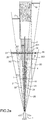
- the figures 2a and 2b illustrate the alignment method according to the invention.
- the figure 2a illustrates the case where the line of sight 10 of the radar is parallel to the axis 4 of the runway.
- the figure 2b illustrates the more general case where the line of sight 10 makes an angle ⁇ with the axis 4 of the track, this angle ⁇ being however small.
- This is indeed the case in practice, since the aircraft is in the final landing phase, having already initiated an alignment process with the runway.
- reference will be made to the particular case of the figure 2a (the calculations applied to case 2a being generalizable to case 2b due to the low value of a), mentioning where necessary the general case of figure 2b .
- the radar sensor makes it possible to fine-tune the alignment with the runway using the method according to the invention , based on relative weighing.
- radar beams 21, 22, 23, 24, 25 are formed, each having a given angular width.
- the beams have substantially the same width, the external beams however being a little wider in the case of using an antenna with electronic scanning.
- certain beams 23 intercept a portion 201 of the track, others 22, 24 intercept the 3D, 3G border of the track, and finally others 21, 25 intercept only the approaches 202 of the track ( typically a grassy area).
- the beams 23 which intercept only a portion of the track give a very low reference backscatter level of the track.
- the beams 21, 25 which intercept only the approaches to the runway give a higher level of backscatter reference.
- the beams 22, 24 which intercept the border give a level of backscatter corresponding to a weighted sum between the track and its surroundings. If the carrier is well aligned with the central axis 4 of the track, there must be symmetry between these beams.
- a differential imbalance appears between the beams which intercept the edges of the runway, this is the concept of relative weighing mentioned previously.
- a differential measurement then makes it possible to measure the positioning of the carrier relative to the axis of the runway. This measurement is only possible if the runway has a uniform backscatter coefficient and if the surrounding area also has a uniform backscatter coefficient over its entire surface. This assumption is reasonable for the current case first grassed.
- a correlation with the readjusted position of the inertial unit and the data thus obtained is made for decision-making.
- the figures 2a and 2b illustrate this principle in a five-beam example.
- These radar beams 21, 22, 23, 24, 25 are shown, and their intersection with the distance and angle resolution plane produces distance-angle boxes.
- Five of these boxes 51, 52, 53, 54, 55 are shown for a given distance. They are delimited angularly by the five radar beams.
- the central beam produces a distance box 53, denoted P, included in the track.
- the most lateral beams 21, 25 produce boxes 51, 55, denoted H, which intercept the surroundings 202 of the track (for example a grassy field).
- Boxes 52, 54 intercepting the left border 3G (box marked G) and the right 3D border (box marked D) of the runway each receives backscattered power for part of runway 2 and for part of the surrounding area 202.
- P (H) and P (P) are respectively the power backscattered per unit of length for the surroundings 202 of the runway (grassy area for example) and for runway 2.
- P (H) and P (P) are known elsewhere and can be easily defined by calibration methods.
- the boxes 53 only present in the track give a first reference level (lowest backscatter level) and the boxes 51, 52 only in the vicinity of the track give another reference level (the most backscatter level Student).
- Knowledge x of allows correcting the steering in order to rally the axis of the runway.
- This basic principle can be extended to several polarizations on transmission and on reception to improve the measurement accuracy.
- Knowing the width of the track makes it possible to know the positioning of the distance-angle boxes with respect to the edges of the track, which consolidates the calculations provided for the weighings (detection of left-right power symmetries).
- the evaluation of the alignment deviation in angle and in position between the carrier and the track can be carried out by a linear interpolation of the deviations x obtained for at least two pairs of distance-angle boxes. This interpolation will advantageously be carried out thanks to all the pairs of distance-angle boxes available in order to improve the precision of the process.
- the figures 2a and 2b give an example of weighing with five beams, in practice one can use a number N of beams, N being greater than 5 and not necessarily odd. The greater the number of beams, the more distance-angle boxes are obtained crossing the edges 3 of the track, making it possible to make a finer weighing.
- the figure 3 summarizes the main steps of the method according to the invention as described above.
- the radar equipping the aircraft forms a number N of beams illuminating said runway and part of the surroundings of said runway.
- the beams emitted have the same angular width.
- a second step 32 the area illuminated by said beams is cut into distance-angle boxes, said beams defining said boxes at an angle. This division is carried out by the radar processing means.
- the radar performs power measurements backscattered by distance-angle boxes, said measurements being carried out for a set of pairs of boxes 52, 54.
- Each couple is composed of two boxes of the same distance, one of which 54 crosses the right 3D edge of the track and the other 52 crosses the left 3G edge.
- a next step 34 performs the calculation, for each pair, of the difference in backscattered power between the right box 54 and the left box 52.
- the aircraft is aligned on the axis 4 when the difference is zero for each pair of boxes. At a minimum, it can be considered that the aircraft is aligned if the difference in backscattered power between the left and the right is zero for at least two pairs of distance-angle boxes.
- the power difference calculation gives the alignment difference x as described above.
- the trajectory of the aircraft is slaved so as to minimize this difference, in other words so that the difference in backscattered power received per pair of boxes 52, 54 tends towards the zero value.
- this difference is transmitted by the radar to the means for piloting the aircraft, these automatic or manual means (by the pilot).
- the threshold of the runway is precisely positioned in distance, by measuring the contrast between the runway and the surrounding area, or between the runway and the runway threshold lamps.
- Certain thresholds are offset from the edge of the runway.
- the positioning of the different recognizable structures (runway edge and runway threshold lamps) relative to the touchdown point can be obtained by learning the runway or injected by precise geometric knowledge of the runway.
- the width of the beams being known as well as that of the track (given in tables), it is also possible, for each beam 22, 24 crossing the track, to locate the distance boxes corresponding to the intersections I, J and K, M between the edges of the beam and the track by a gradient calculation of the backscattered power along the distance axis.
- This method refines the estimated difference between the line of sight of radar 10 and the axis of runway 4.
- the taking of images being carried out at a relatively high rate it may be appropriate to integrate the information over time in order to refine the estimates of alignment and precise positioning over time.
- the displacement of the carrier can be compensated for by taking into account its speed vector, in particular for taking into account the distance of the different boxes.
- filtering for example of the “alpha beta” type
Landscapes
- Engineering & Computer Science (AREA)
- Radar, Positioning & Navigation (AREA)
- Remote Sensing (AREA)
- Physics & Mathematics (AREA)
- Computer Networks & Wireless Communication (AREA)
- General Physics & Mathematics (AREA)
- Electromagnetism (AREA)
- Aviation & Aerospace Engineering (AREA)
- Radar Systems Or Details Thereof (AREA)
- Traffic Control Systems (AREA)
Applications Claiming Priority (1)
| Application Number | Priority Date | Filing Date | Title |
|---|---|---|---|
| FR1872814A FR3090175B1 (fr) | 2018-12-13 | 2018-12-13 | Procede et dispositif d’aide a l’atterrissage d’un aeronef pour aligner ledit aeronef sur une piste d’atterrissage |
Publications (2)
| Publication Number | Publication Date |
|---|---|
| EP3667366A1 true EP3667366A1 (de) | 2020-06-17 |
| EP3667366B1 EP3667366B1 (de) | 2021-10-27 |
Family
ID=67185103
Family Applications (1)
| Application Number | Title | Priority Date | Filing Date |
|---|---|---|---|
| EP19209747.5A Active EP3667366B1 (de) | 2018-12-13 | 2019-11-18 | Verfahren und vorrichtung zur landeunterstützung für luftfahrzeug zur ausrichtung des luftfahrzeugs auf die landebahn |
Country Status (4)
| Country | Link |
|---|---|
| US (1) | US11137492B2 (de) |
| EP (1) | EP3667366B1 (de) |
| CN (1) | CN111319779B (de) |
| FR (1) | FR3090175B1 (de) |
Citations (4)
| Publication number | Priority date | Publication date | Assignee | Title |
|---|---|---|---|---|
| US5640165A (en) * | 1995-06-07 | 1997-06-17 | Hughes Electronics | Range cell formation processing |
| US7619556B1 (en) * | 2008-02-28 | 2009-11-17 | Rockwell Collins, Inc. | System and method for synthesizing localizer and glide slope deviations from weather radar |
| EP3214461A1 (de) * | 2016-03-02 | 2017-09-06 | The Boeing Company | Flugzeuglandesysteme und -verfahren |
| US20180259641A1 (en) * | 2017-03-13 | 2018-09-13 | Honeywell International Inc. | Methods for a multi-function electronically steered weather radar |
Family Cites Families (6)
| Publication number | Priority date | Publication date | Assignee | Title |
|---|---|---|---|---|
| US20020017042A1 (en) * | 2000-06-23 | 2002-02-14 | Schieferstein Wesley E. | Reboundable retroreflective runway approach panels |
| CN101295021A (zh) * | 2007-04-24 | 2008-10-29 | 上海民航华东激光科技有限公司 | 激光引导飞机着陆系统及使用方法 |
| CN103043220B (zh) * | 2011-10-13 | 2015-07-01 | 王力丰 | 航空母舰舰载机起降系统及其起降方法 |
| FR3024127B1 (fr) * | 2014-07-25 | 2016-08-26 | Airbus Operations Sas | Procede et systeme d'atterrissage automatique autonome |
| EP3483802B1 (de) * | 2017-11-13 | 2025-01-01 | The Boeing Company | System und verfahren zur bestimmung der start- und landebahnkonfiguration eines flughafens |
| US11094210B2 (en) * | 2018-05-09 | 2021-08-17 | Simmonds Precision Products, Inc. | Airport surface navigation aid |
-
2018
- 2018-12-13 FR FR1872814A patent/FR3090175B1/fr not_active Expired - Fee Related
-
2019
- 2019-11-18 EP EP19209747.5A patent/EP3667366B1/de active Active
- 2019-11-21 US US16/691,005 patent/US11137492B2/en active Active
- 2019-12-13 CN CN201911280064.0A patent/CN111319779B/zh active Active
Patent Citations (4)
| Publication number | Priority date | Publication date | Assignee | Title |
|---|---|---|---|---|
| US5640165A (en) * | 1995-06-07 | 1997-06-17 | Hughes Electronics | Range cell formation processing |
| US7619556B1 (en) * | 2008-02-28 | 2009-11-17 | Rockwell Collins, Inc. | System and method for synthesizing localizer and glide slope deviations from weather radar |
| EP3214461A1 (de) * | 2016-03-02 | 2017-09-06 | The Boeing Company | Flugzeuglandesysteme und -verfahren |
| US20180259641A1 (en) * | 2017-03-13 | 2018-09-13 | Honeywell International Inc. | Methods for a multi-function electronically steered weather radar |
Non-Patent Citations (2)
| Title |
|---|
| BRAILOVSKY ALEXANDER ET AL: "REVS: a radar-based enhanced vision system for degraded visual environments", VISUAL COMMUNICATIONS AND IMAGE PROCESSING; 20-1-2004 - 20-1-2004; SAN JOSE,, vol. 9087, 19 June 2014 (2014-06-19), pages 908708 - 908708, XP060037250, ISBN: 978-1-62841-730-2, DOI: 10.1117/12.2053084 * |
| VAN CAEKENBERGHE K ET AL: "A 94 GHz OFDM Frequency Scanning Radar for Autonomous Landing Guidance", RADAR CONFERENCE, 2007 IEEE, IEEE, PI, 17 April 2007 (2007-04-17), pages 248 - 253, XP031214565, ISBN: 978-1-4244-0283-0 * |
Also Published As
| Publication number | Publication date |
|---|---|
| CN111319779A (zh) | 2020-06-23 |
| US20200191948A1 (en) | 2020-06-18 |
| CN111319779B (zh) | 2024-03-19 |
| EP3667366B1 (de) | 2021-10-27 |
| FR3090175A1 (fr) | 2020-06-19 |
| FR3090175B1 (fr) | 2020-11-13 |
| US11137492B2 (en) | 2021-10-05 |
Similar Documents
| Publication | Publication Date | Title |
|---|---|---|
| EP3657213B1 (de) | Lernverfahren eines neuronennetzes an bord eines luftfahrzeugs für die landehilfe dieses luftfahrzeugs, und server für die umsetzung eines solchen verfahrens | |
| EP0678841B1 (de) | Landungshilfevorrichtung | |
| EP4217761B1 (de) | Verfahren zur ortung eines flugzeugs im flug | |
| EP1870789B1 (de) | System zur Erfassung von Hindernissen in der Umgebung eines Landungspunktes | |
| FR3016222A1 (fr) | Procede et dispositif de guidage vertical d'un aeronef lors d'une approche d'une piste d'atterrissage le long d'une trajectoire laterale d'approche. | |
| EP2225622B1 (de) | Verfahren zur flugzeuglandeunterstützung mithilfe von gps und mls im falle einer berechneten axial-annäherung | |
| FR2638544A1 (fr) | Systeme pour determiner la position spatiale d'un objet en mouvement, applique notamment a l'atterrissage des avions | |
| FR2983799A1 (fr) | Procede et dispositif de commande de l'emission lumineuse d'un projecteur de vehicule | |
| FR2887065A1 (fr) | Procede et systeme d'aide au pilotage d'un aeronef volant a basse altitude | |
| EP3226062B1 (de) | Verfahren zur synthetischen darstellung von wichtigen elementen in einem visualisierungssystem eines luftfahrzeugs | |
| EP3656681A1 (de) | Vorrichtung und verfahren zur landungsunterstützung eines luftfahrzeugs bei eingeschränkten sichtbedingungen | |
| FR2887329A1 (fr) | Procede et dispositif d'affichage pour un aeronef qui suit un plan de vol | |
| FR2928021A1 (fr) | Procede et dispositif de detection d'un aeronef environnant. | |
| FR3077393A1 (fr) | Véhicules aériens à vision artificielle | |
| CA2160759C (fr) | Dispositif optoelectronique d'aide au pilotage d'un aeronef | |
| FR3103050A1 (fr) | Procede et dispositif d'aide a l'atterrissage d'aeronef en conditions de visibilite degradee | |
| FR3016224A1 (fr) | Procede et dispositif de guidage d'un aeronef lors d'un vol a basse hauteur. | |
| EP3667366B1 (de) | Verfahren und vorrichtung zur landeunterstützung für luftfahrzeug zur ausrichtung des luftfahrzeugs auf die landebahn | |
| EP2407953A1 (de) | Verbessertes Pilotenassistenzverfahren für Luftfahrzeug | |
| US20220155460A1 (en) | Remote airflow observation device, remote airflow observation method, and program | |
| EP1459979B1 (de) | Verfahren und Vorrichtung zur Bestimmung von mindestens einer Angabe bezüglich der vertikalen Position eines Luftfahrzeuges | |
| EP0539264B1 (de) | Verfahren und Vorrichtung zum Determinieren der Orientation eines Objektes | |
| US12504538B2 (en) | Distance-velocity disambiguation in hybrid light detection and ranging devices | |
| WO2023110206A1 (fr) | Système de mesure aéroporté comprenant une caméra spad | |
| EP3866136A1 (de) | Verfahren und system zur navigationshilfe für ein luftfahrzeug durch erkennung von maritimen objekten beim anflug, im stationären flugzustand oder bei der landung |
Legal Events
| Date | Code | Title | Description |
|---|---|---|---|
| PUAI | Public reference made under article 153(3) epc to a published international application that has entered the european phase |
Free format text: ORIGINAL CODE: 0009012 |
|
| STAA | Information on the status of an ep patent application or granted ep patent |
Free format text: STATUS: REQUEST FOR EXAMINATION WAS MADE |
|
| 17P | Request for examination filed |
Effective date: 20200414 |
|
| AK | Designated contracting states |
Kind code of ref document: A1 Designated state(s): AL AT BE BG CH CY CZ DE DK EE ES FI FR GB GR HR HU IE IS IT LI LT LU LV MC MK MT NL NO PL PT RO RS SE SI SK SM TR |
|
| AX | Request for extension of the european patent |
Extension state: BA ME |
|
| GRAP | Despatch of communication of intention to grant a patent |
Free format text: ORIGINAL CODE: EPIDOSNIGR1 |
|
| STAA | Information on the status of an ep patent application or granted ep patent |
Free format text: STATUS: GRANT OF PATENT IS INTENDED |
|
| INTG | Intention to grant announced |
Effective date: 20210608 |
|
| GRAS | Grant fee paid |
Free format text: ORIGINAL CODE: EPIDOSNIGR3 |
|
| GRAA | (expected) grant |
Free format text: ORIGINAL CODE: 0009210 |
|
| STAA | Information on the status of an ep patent application or granted ep patent |
Free format text: STATUS: THE PATENT HAS BEEN GRANTED |
|
| AK | Designated contracting states |
Kind code of ref document: B1 Designated state(s): AL AT BE BG CH CY CZ DE DK EE ES FI FR GB GR HR HU IE IS IT LI LT LU LV MC MK MT NL NO PL PT RO RS SE SI SK SM TR |
|
| REG | Reference to a national code |
Ref country code: GB Ref legal event code: FG4D Free format text: NOT ENGLISH |
|
| REG | Reference to a national code |
Ref country code: CH Ref legal event code: EP |
|
| REG | Reference to a national code |
Ref country code: DE Ref legal event code: R096 Ref document number: 602019008699 Country of ref document: DE |
|
| REG | Reference to a national code |
Ref country code: AT Ref legal event code: REF Ref document number: 1442273 Country of ref document: AT Kind code of ref document: T Effective date: 20211115 |
|
| REG | Reference to a national code |
Ref country code: IE Ref legal event code: FG4D Free format text: LANGUAGE OF EP DOCUMENT: FRENCH |
|
| REG | Reference to a national code |
Ref country code: LT Ref legal event code: MG9D |
|
| REG | Reference to a national code |
Ref country code: NL Ref legal event code: MP Effective date: 20211027 |
|
| REG | Reference to a national code |
Ref country code: AT Ref legal event code: MK05 Ref document number: 1442273 Country of ref document: AT Kind code of ref document: T Effective date: 20211027 |
|
| PG25 | Lapsed in a contracting state [announced via postgrant information from national office to epo] |
Ref country code: RS Free format text: LAPSE BECAUSE OF FAILURE TO SUBMIT A TRANSLATION OF THE DESCRIPTION OR TO PAY THE FEE WITHIN THE PRESCRIBED TIME-LIMIT Effective date: 20211027 Ref country code: LT Free format text: LAPSE BECAUSE OF FAILURE TO SUBMIT A TRANSLATION OF THE DESCRIPTION OR TO PAY THE FEE WITHIN THE PRESCRIBED TIME-LIMIT Effective date: 20211027 Ref country code: FI Free format text: LAPSE BECAUSE OF FAILURE TO SUBMIT A TRANSLATION OF THE DESCRIPTION OR TO PAY THE FEE WITHIN THE PRESCRIBED TIME-LIMIT Effective date: 20211027 Ref country code: BG Free format text: LAPSE BECAUSE OF FAILURE TO SUBMIT A TRANSLATION OF THE DESCRIPTION OR TO PAY THE FEE WITHIN THE PRESCRIBED TIME-LIMIT Effective date: 20220127 Ref country code: AT Free format text: LAPSE BECAUSE OF FAILURE TO SUBMIT A TRANSLATION OF THE DESCRIPTION OR TO PAY THE FEE WITHIN THE PRESCRIBED TIME-LIMIT Effective date: 20211027 |
|
| PG25 | Lapsed in a contracting state [announced via postgrant information from national office to epo] |
Ref country code: IS Free format text: LAPSE BECAUSE OF FAILURE TO SUBMIT A TRANSLATION OF THE DESCRIPTION OR TO PAY THE FEE WITHIN THE PRESCRIBED TIME-LIMIT Effective date: 20220227 Ref country code: SE Free format text: LAPSE BECAUSE OF FAILURE TO SUBMIT A TRANSLATION OF THE DESCRIPTION OR TO PAY THE FEE WITHIN THE PRESCRIBED TIME-LIMIT Effective date: 20211027 Ref country code: PT Free format text: LAPSE BECAUSE OF FAILURE TO SUBMIT A TRANSLATION OF THE DESCRIPTION OR TO PAY THE FEE WITHIN THE PRESCRIBED TIME-LIMIT Effective date: 20220228 Ref country code: PL Free format text: LAPSE BECAUSE OF FAILURE TO SUBMIT A TRANSLATION OF THE DESCRIPTION OR TO PAY THE FEE WITHIN THE PRESCRIBED TIME-LIMIT Effective date: 20211027 Ref country code: NO Free format text: LAPSE BECAUSE OF FAILURE TO SUBMIT A TRANSLATION OF THE DESCRIPTION OR TO PAY THE FEE WITHIN THE PRESCRIBED TIME-LIMIT Effective date: 20220127 Ref country code: NL Free format text: LAPSE BECAUSE OF FAILURE TO SUBMIT A TRANSLATION OF THE DESCRIPTION OR TO PAY THE FEE WITHIN THE PRESCRIBED TIME-LIMIT Effective date: 20211027 Ref country code: LV Free format text: LAPSE BECAUSE OF FAILURE TO SUBMIT A TRANSLATION OF THE DESCRIPTION OR TO PAY THE FEE WITHIN THE PRESCRIBED TIME-LIMIT Effective date: 20211027 Ref country code: HR Free format text: LAPSE BECAUSE OF FAILURE TO SUBMIT A TRANSLATION OF THE DESCRIPTION OR TO PAY THE FEE WITHIN THE PRESCRIBED TIME-LIMIT Effective date: 20211027 Ref country code: GR Free format text: LAPSE BECAUSE OF FAILURE TO SUBMIT A TRANSLATION OF THE DESCRIPTION OR TO PAY THE FEE WITHIN THE PRESCRIBED TIME-LIMIT Effective date: 20220128 Ref country code: ES Free format text: LAPSE BECAUSE OF FAILURE TO SUBMIT A TRANSLATION OF THE DESCRIPTION OR TO PAY THE FEE WITHIN THE PRESCRIBED TIME-LIMIT Effective date: 20211027 |
|
| REG | Reference to a national code |
Ref country code: DE Ref legal event code: R097 Ref document number: 602019008699 Country of ref document: DE |
|
| PG25 | Lapsed in a contracting state [announced via postgrant information from national office to epo] |
Ref country code: SM Free format text: LAPSE BECAUSE OF FAILURE TO SUBMIT A TRANSLATION OF THE DESCRIPTION OR TO PAY THE FEE WITHIN THE PRESCRIBED TIME-LIMIT Effective date: 20211027 Ref country code: SK Free format text: LAPSE BECAUSE OF FAILURE TO SUBMIT A TRANSLATION OF THE DESCRIPTION OR TO PAY THE FEE WITHIN THE PRESCRIBED TIME-LIMIT Effective date: 20211027 Ref country code: RO Free format text: LAPSE BECAUSE OF FAILURE TO SUBMIT A TRANSLATION OF THE DESCRIPTION OR TO PAY THE FEE WITHIN THE PRESCRIBED TIME-LIMIT Effective date: 20211027 Ref country code: MC Free format text: LAPSE BECAUSE OF FAILURE TO SUBMIT A TRANSLATION OF THE DESCRIPTION OR TO PAY THE FEE WITHIN THE PRESCRIBED TIME-LIMIT Effective date: 20211027 Ref country code: LU Free format text: LAPSE BECAUSE OF NON-PAYMENT OF DUE FEES Effective date: 20211118 Ref country code: EE Free format text: LAPSE BECAUSE OF FAILURE TO SUBMIT A TRANSLATION OF THE DESCRIPTION OR TO PAY THE FEE WITHIN THE PRESCRIBED TIME-LIMIT Effective date: 20211027 Ref country code: DK Free format text: LAPSE BECAUSE OF FAILURE TO SUBMIT A TRANSLATION OF THE DESCRIPTION OR TO PAY THE FEE WITHIN THE PRESCRIBED TIME-LIMIT Effective date: 20211027 Ref country code: CZ Free format text: LAPSE BECAUSE OF FAILURE TO SUBMIT A TRANSLATION OF THE DESCRIPTION OR TO PAY THE FEE WITHIN THE PRESCRIBED TIME-LIMIT Effective date: 20211027 Ref country code: BE Free format text: LAPSE BECAUSE OF NON-PAYMENT OF DUE FEES Effective date: 20211130 |
|
| REG | Reference to a national code |
Ref country code: BE Ref legal event code: MM Effective date: 20211130 |
|
| PLBE | No opposition filed within time limit |
Free format text: ORIGINAL CODE: 0009261 |
|
| STAA | Information on the status of an ep patent application or granted ep patent |
Free format text: STATUS: NO OPPOSITION FILED WITHIN TIME LIMIT |
|
| 26N | No opposition filed |
Effective date: 20220728 |
|
| PG25 | Lapsed in a contracting state [announced via postgrant information from national office to epo] |
Ref country code: IE Free format text: LAPSE BECAUSE OF NON-PAYMENT OF DUE FEES Effective date: 20211118 Ref country code: AL Free format text: LAPSE BECAUSE OF FAILURE TO SUBMIT A TRANSLATION OF THE DESCRIPTION OR TO PAY THE FEE WITHIN THE PRESCRIBED TIME-LIMIT Effective date: 20211027 |
|
| PG25 | Lapsed in a contracting state [announced via postgrant information from national office to epo] |
Ref country code: SI Free format text: LAPSE BECAUSE OF FAILURE TO SUBMIT A TRANSLATION OF THE DESCRIPTION OR TO PAY THE FEE WITHIN THE PRESCRIBED TIME-LIMIT Effective date: 20211027 |
|
| PG25 | Lapsed in a contracting state [announced via postgrant information from national office to epo] |
Ref country code: IT Free format text: LAPSE BECAUSE OF FAILURE TO SUBMIT A TRANSLATION OF THE DESCRIPTION OR TO PAY THE FEE WITHIN THE PRESCRIBED TIME-LIMIT Effective date: 20211027 |
|
| P01 | Opt-out of the competence of the unified patent court (upc) registered |
Effective date: 20230427 |
|
| PG25 | Lapsed in a contracting state [announced via postgrant information from national office to epo] |
Ref country code: CY Free format text: LAPSE BECAUSE OF FAILURE TO SUBMIT A TRANSLATION OF THE DESCRIPTION OR TO PAY THE FEE WITHIN THE PRESCRIBED TIME-LIMIT Effective date: 20211027 |
|
| REG | Reference to a national code |
Ref country code: CH Ref legal event code: PL |
|
| PG25 | Lapsed in a contracting state [announced via postgrant information from national office to epo] |
Ref country code: LI Free format text: LAPSE BECAUSE OF NON-PAYMENT OF DUE FEES Effective date: 20221130 Ref country code: HU Free format text: LAPSE BECAUSE OF FAILURE TO SUBMIT A TRANSLATION OF THE DESCRIPTION OR TO PAY THE FEE WITHIN THE PRESCRIBED TIME-LIMIT; INVALID AB INITIO Effective date: 20191118 Ref country code: CH Free format text: LAPSE BECAUSE OF NON-PAYMENT OF DUE FEES Effective date: 20221130 |
|
| PG25 | Lapsed in a contracting state [announced via postgrant information from national office to epo] |
Ref country code: MK Free format text: LAPSE BECAUSE OF FAILURE TO SUBMIT A TRANSLATION OF THE DESCRIPTION OR TO PAY THE FEE WITHIN THE PRESCRIBED TIME-LIMIT Effective date: 20211027 |
|
| GBPC | Gb: european patent ceased through non-payment of renewal fee |
Effective date: 20231118 |
|
| PG25 | Lapsed in a contracting state [announced via postgrant information from national office to epo] |
Ref country code: MT Free format text: LAPSE BECAUSE OF FAILURE TO SUBMIT A TRANSLATION OF THE DESCRIPTION OR TO PAY THE FEE WITHIN THE PRESCRIBED TIME-LIMIT Effective date: 20211027 |
|
| PG25 | Lapsed in a contracting state [announced via postgrant information from national office to epo] |
Ref country code: GB Free format text: LAPSE BECAUSE OF NON-PAYMENT OF DUE FEES Effective date: 20231118 |
|
| PG25 | Lapsed in a contracting state [announced via postgrant information from national office to epo] |
Ref country code: GB Free format text: LAPSE BECAUSE OF NON-PAYMENT OF DUE FEES Effective date: 20231118 |
|
| PG25 | Lapsed in a contracting state [announced via postgrant information from national office to epo] |
Ref country code: TR Free format text: LAPSE BECAUSE OF FAILURE TO SUBMIT A TRANSLATION OF THE DESCRIPTION OR TO PAY THE FEE WITHIN THE PRESCRIBED TIME-LIMIT Effective date: 20211027 |
|
| PGFP | Annual fee paid to national office [announced via postgrant information from national office to epo] |
Ref country code: DE Payment date: 20251014 Year of fee payment: 7 |
|
| PGFP | Annual fee paid to national office [announced via postgrant information from national office to epo] |
Ref country code: FR Payment date: 20251023 Year of fee payment: 7 |