EP3667390B1 - Procédé et générateur de signal destinés à entraîner un élément acousto-optique - Google Patents
Procédé et générateur de signal destinés à entraîner un élément acousto-optique Download PDFInfo
- Publication number
- EP3667390B1 EP3667390B1 EP19215791.5A EP19215791A EP3667390B1 EP 3667390 B1 EP3667390 B1 EP 3667390B1 EP 19215791 A EP19215791 A EP 19215791A EP 3667390 B1 EP3667390 B1 EP 3667390B1
- Authority
- EP
- European Patent Office
- Prior art keywords
- acousto
- optic
- crystal
- frequency
- driving
- Prior art date
- Legal status (The legal status is an assumption and is not a legal conclusion. Google has not performed a legal analysis and makes no representation as to the accuracy of the status listed.)
- Active
Links
Images


Classifications
-
- H—ELECTRICITY
- H03—ELECTRONIC CIRCUITRY
- H03K—PULSE TECHNIQUE
- H03K5/00—Manipulating of pulses not covered by one of the other main groups of this subclass
- H03K5/153—Arrangements in which a pulse is delivered at the instant when a predetermined characteristic of an input signal is present or at a fixed time interval after this instant
- H03K5/1534—Transition or edge detectors
-
- G—PHYSICS
- G02—OPTICS
- G02B—OPTICAL ELEMENTS, SYSTEMS OR APPARATUS
- G02B21/00—Microscopes
- G02B21/0004—Microscopes specially adapted for specific applications
- G02B21/002—Scanning microscopes
- G02B21/0024—Confocal scanning microscopes (CSOMs) or confocal "macroscopes"; Accessories which are not restricted to use with CSOMs, e.g. sample holders
- G02B21/0032—Optical details of illumination, e.g. light-sources, pinholes, beam splitters, slits, fibers
-
- G—PHYSICS
- G02—OPTICS
- G02F—OPTICAL DEVICES OR ARRANGEMENTS FOR THE CONTROL OF LIGHT BY MODIFICATION OF THE OPTICAL PROPERTIES OF THE MEDIA OF THE ELEMENTS INVOLVED THEREIN; NON-LINEAR OPTICS; FREQUENCY-CHANGING OF LIGHT; OPTICAL LOGIC ELEMENTS; OPTICAL ANALOGUE/DIGITAL CONVERTERS
- G02F1/00—Devices or arrangements for the control of the intensity, colour, phase, polarisation or direction of light arriving from an independent light source, e.g. switching, gating or modulating; Non-linear optics
- G02F1/29—Devices or arrangements for the control of the intensity, colour, phase, polarisation or direction of light arriving from an independent light source, e.g. switching, gating or modulating; Non-linear optics for the control of the position or the direction of light beams, i.e. deflection
- G02F1/33—Acousto-optical deflection devices
-
- G—PHYSICS
- G02—OPTICS
- G02B—OPTICAL ELEMENTS, SYSTEMS OR APPARATUS
- G02B21/00—Microscopes
- G02B21/0004—Microscopes specially adapted for specific applications
- G02B21/002—Scanning microscopes
- G02B21/0024—Confocal scanning microscopes (CSOMs) or confocal "macroscopes"; Accessories which are not restricted to use with CSOMs, e.g. sample holders
- G02B21/0052—Optical details of the image generation
- G02B21/0076—Optical details of the image generation arrangements using fluorescence or luminescence
-
- G—PHYSICS
- G02—OPTICS
- G02F—OPTICAL DEVICES OR ARRANGEMENTS FOR THE CONTROL OF LIGHT BY MODIFICATION OF THE OPTICAL PROPERTIES OF THE MEDIA OF THE ELEMENTS INVOLVED THEREIN; NON-LINEAR OPTICS; FREQUENCY-CHANGING OF LIGHT; OPTICAL LOGIC ELEMENTS; OPTICAL ANALOGUE/DIGITAL CONVERTERS
- G02F1/00—Devices or arrangements for the control of the intensity, colour, phase, polarisation or direction of light arriving from an independent light source, e.g. switching, gating or modulating; Non-linear optics
- G02F1/01—Devices or arrangements for the control of the intensity, colour, phase, polarisation or direction of light arriving from an independent light source, e.g. switching, gating or modulating; Non-linear optics for the control of the intensity, phase, polarisation or colour
- G02F1/11—Devices or arrangements for the control of the intensity, colour, phase, polarisation or direction of light arriving from an independent light source, e.g. switching, gating or modulating; Non-linear optics for the control of the intensity, phase, polarisation or colour based on acousto-optical elements, e.g. using variable diffraction by sound or like mechanical waves
- G02F1/113—Circuit or control arrangements
-
- H—ELECTRICITY
- H01—ELECTRIC ELEMENTS
- H01S—DEVICES USING THE PROCESS OF LIGHT AMPLIFICATION BY STIMULATED EMISSION OF RADIATION [LASER] TO AMPLIFY OR GENERATE LIGHT; DEVICES USING STIMULATED EMISSION OF ELECTROMAGNETIC RADIATION IN WAVE RANGES OTHER THAN OPTICAL
- H01S3/00—Lasers, i.e. devices using stimulated emission of electromagnetic radiation in the infrared, visible or ultraviolet wave range
- H01S3/005—Optical devices external to the laser cavity, specially adapted for lasers, e.g. for homogenisation of the beam or for manipulating laser pulses, e.g. pulse shaping
- H01S3/0057—Temporal shaping, e.g. pulse compression, frequency chirping
-
- G—PHYSICS
- G02—OPTICS
- G02B—OPTICAL ELEMENTS, SYSTEMS OR APPARATUS
- G02B21/00—Microscopes
- G02B21/0004—Microscopes specially adapted for specific applications
- G02B21/002—Scanning microscopes
- G02B21/0024—Confocal scanning microscopes (CSOMs) or confocal "macroscopes"; Accessories which are not restricted to use with CSOMs, e.g. sample holders
- G02B21/0052—Optical details of the image generation
- G02B21/0064—Optical details of the image generation multi-spectral or wavelength-selective arrangements, e.g. wavelength fan-out, chromatic profiling
Definitions
- the present invention relates to a method and a signal generator for controlling an acousto-optical element, an arrangement comprising such a signal generator and an acousto-optical element, and a microscope with such an arrangement.
- excitation light with one or more specified wavelengths.
- one or more excitation light beams which usually have to have specified spectral properties, may be necessary.
- wavelength-selective elements based on the acousto-optical effect can be used.
- acousto-optical elements usually have a so-called acousto-optical crystal, which is set into vibration by an acoustic signal generator, also known as a transducer.
- a transducer usually has a piezoelectric material and two or more electrodes that contact this material.
- the piezoelectric material is excited to vibrate, so that an acoustic wave can be created that passes through the crystal.
- Acousto-optical crystals are characterized by the fact that the resulting sound wave changes the optical properties of the crystal.
- acousto-optical elements which can also be used advantageously within the scope of the invention, are acousto-optical tunable filters (AOTF), acousto-optical modulators (AOM), acousto-optical deflectors (AOD), acousto-optical beam splitters (AOBS) and acousto-optical beam combiners (AOBM).
- AOTF acousto-optical tunable filters
- AOM acousto-optical modulators
- AOD acousto-optical deflectors
- AOBS acousto-optical beam splitters
- AOBM acousto-optical beam combiners
- the high-frequency electrical signals for the converter are usually generated in a frequency generator (for example a voltage-controlled oscillator (VCO), a phase-locked loop (PLL), or a synthesizer using the DDS method (direct digital synthesis)) and amplified using a high-frequency amplifier so that the amplitude is large enough to make the crystal oscillate.
- a frequency generator for example a voltage-controlled oscillator (VCO), a phase-locked loop (PLL), or a synthesizer using the DDS method (direct digital synthesis)
- VCO voltage-controlled oscillator
- PLL phase-locked loop
- DDS method direct digital synthesis
- the passband width of acousto-optical modulators can be varied by structural measures such as the design of the crystal geometry and/or the transducer and by the curve shape of the control signal.
- structural measures such as the design of the crystal geometry and/or the transducer and by the curve shape of the control signal.
- several closely spaced frequencies can be superimposed and fed into the crystal, which causes the individual passbands to overlap to form a larger passband.
- the disadvantage of these methods is that the broadening of the passband curve cannot be changed in the constructive solution. If different passband widths are required, the crystals must be exchanged. Furthermore, the passband widths in the entire spectral range of the crystal are predetermined by the geometry. With the superposition solution, high peak powers arise that must be processed by the RF amplifier used. To ensure that the amplifier does not produce mixed products due to non-linear behavior, its linear range must be very large. This means that the amplifier must deliver a significantly higher peak power compared to the average power. This makes the amplifier significantly more expensive. If the differences between the individual frequencies are unfavorable to one another, mixed products can arise, which, for example, when using a white light laser as a light source, leads to unwanted colors being switched on.
- GB 2 427 034 A discloses an acousto-optical crystal and a piezoelectric transducer for displacing the acousto-optical crystal in mechanical vibrations.
- the acousto-optical crystal is controlled with two different control frequencies, whereby the grating generated by density fluctuations can have different grating spacings at the same time.
- WO 2017/207664 A1 discloses the control of an acousto-optical crystal with two different frequencies. Different pulsed light beams can hit different excitation frequencies of the acousto-optical crystal.
- EN 10 2013 201 968 A1 discloses an acousto-optical deflector, whereby two oscillation frequencies can be generated simultaneously in the crystal.
- WO 2018/197546 A1 discloses a method for controlling an acousto-optical element with a control signal that is generated by means of a DDS method with a signal value sequence that is composed of at least two frequency components.
- JP 2000 149337 A shows an exposure device for optical disks in which laser beams are focused on a rotating exposure master disk on which a photoresist is applied in order to expose a row of pits or a groove.
- An acousto-optical element is arranged in the beam path.
- Several high-frequency signal generators are arranged, which apply drive signals with different frequencies to the acousto-optical element.
- a high-speed switching element and a pulse signal generator are provided, which sequentially and repeatedly apply one of the drive signals generated by the high-frequency signal generators to the acousto-optical element.
- the invention is based on the measure of exposing an acousto-optical crystal to a sound wave whose frequency varies so quickly over time that a lattice with several lattice constants is effectively formed.
- a sound wave in an acousto-optical crystal leads to a lattice structure whose lattice constant depends on the frequency of the sound and the speed of sound in the crystal. If a laser beam passes through this lattice structure and the dimensions of the structure and the wavelength of the light match, part of the laser light is deflected by a diffraction process. Some light is continuously deflected along the beam path in the sound field. If you look at the amount of deflected light along a small part of the beam path in the sound field, this is correlated with the sound power and thus the shape of the lattice created by the sound. The amplitude and thus the shape of the lattice thus determines the amount of deflected light. The maximum amount of deflected light is reached when all of the light that can be deflected in principle has been deflected at the point where the light beam leaves the sound field.
- the sound-generating frequency is not constant, but alternates between several different values around a center frequency, then a lattice structure is created with lattice constants that change in zones. These several different values are also referred to below as the center frequency spectrum.
- the center frequency itself can, but does not have to, be part of the center frequency spectrum.
- Each of these zones deflects light from a specific wavelength range. Since the light beam passes through several zones in succession, some light of a different wavelength is deflected in each zone. In order to deflect the same amount of light as in the monochromatic case, the grating intensity and thus the sound power can be somewhat higher. If the frequencies are switched quickly enough, there are always several zones with the same lattice constant in the crystal. This ensures that the spectrum of the deflected light is constant over time.
- the control frequency can alternately assume several different values around a center frequency during a passage of a mechanical oscillation wave through the acousto-optical crystal
- the switching takes place taking into account the crystal expansion and the speed of sound in the crystal.
- These values determine the time that a mechanical oscillation wave needs to pass through the crystal and during which the frequency of the control signal must assume at least two different values at least once. Preferably, however, it assumes the at least two different values several times during this time.
- control frequency takes on two to eight different values. This is practical because different wavelength ranges of light can be deflected in this way, but at the same time the switching can take place quickly enough so that the intensity of the deflected light is sufficiently high.
- the several different values are in a bandwidth of 50 kHz - 1 MHz around the center frequency.
- control signal has a constant amplitude for each control frequency.
- different amplitudes for the different control frequencies are also conceivable.
- it can be advantageous It may be necessary to apply a higher amplitude at higher frequencies due to the damping behavior.
- a suitable type of switching should be jump-free, i.e. the curve of the control signal for the sound generation should be continuous. Otherwise, undesirable harmonics would be generated. Furthermore, a frequency should be present for at least one complete period, preferably a plurality of complete periods, in order to build up a clear grid structure.
- the at least one control frequency is periodically changed so quickly that a light beam that enters the acousto-optical crystal - in particular not perpendicular to the mechanical oscillation wave - hits the same grating spacing at least twice. This ensures that the spectrum of the deflected light is constant over time.
- the at least one control frequency is periodically changed so quickly that the light beam hits the same grating spacing at least three or more times. In this way, the uniformity of the light deflection can be further improved.
- Figure 1 shows schematically an arrangement 100 according to a preferred embodiment of the invention.
- the arrangement 100 comprises a signal generator 101. This serves to control an acousto-optical element 200, which has an acousto-optical crystal 202 and a piezoelectric converter 201 for setting the crystal 202 into mechanical vibrations.
- the acousto-optical element serves to influence light in a desired manner, e.g. as an AOTF.
- the mechanical vibrations cause density fluctuations in the crystal, which function as an optical grating, as in Figure 3 indicated.
- the signal generator 101 is configured to control the piezoelectric transducer 201 with a control signal 300 having at least one control frequency f, wherein the at least one control frequency f alternately assumes several different values around a center frequency during a passage of a mechanical oscillation wave 301 through the acousto-optical crystal 202, so that a grating generated by density fluctuations in the acousto-optical crystal 202 simultaneously has different grating spacings.
- Figure 2 shows an example of such a control signal 300.
- the control frequency f alternately takes on two different values f 1 , f 2 .
- it takes on the value f 1 between time t 0 and time t 1 , the value f 2 between t 1 and t 2 , the value f 1 between t 2 and t 3 and the value f 2 between t 3 and t 4.
- the curve of the control signal 300 is nevertheless continuous and jump-free.
- the control frequency f of the control signal 300 is always constant for at least one oscillation period, more precisely in this example exactly four oscillation periods.
- FIG. 3 shows an acousto-optical element 200 which is controlled according to an embodiment of a method according to the invention.
- the acousto-optical element 200 has an acousto-optical crystal 202 and a piezoelectric transducer 201 for setting the crystal 202 into mechanical vibrations.
- the piezoelectric transducer 201 is controlled by a control signal 300 with at least one control frequency f, wherein the at least one control frequency f alternately assumes three different values during a passage of a mechanical oscillation wave through the acousto-optical crystal 202.
- a mechanical vibration wave 301 is formed, which continues through the acousto-optical crystal 202 as an acoustic sound wave.
- a lattice structure is created with zone-wise changing lattice constants, whereby Figure 3 the lattice structure is shown for a specific point in time.
- zones are marked with different hatching and are labelled z1, z2, z3, z4, z5, z6, z7, z8, z9, z10, z11 and z12.
- a lattice constant is repeated every three zones.
- zones z1, z4, z7 and z10 as well as zones z2, z5, z8 and z11 as well as zones z3, z6, z9 and z12 each have the same lattice constant. This is shown in the figure by the fact that zones with the same lattice constant each have the same hatching.
- the acousto-optical crystal is used to deflect light rays. If a light ray passes through this lattice structure and the dimensions of the structure and the wavelength of the light match, part of the light ray is deflected by a diffraction process. Each of these zones deflects light of a specific wavelength range. Since the light ray passes through several zones z1, ..., z12 in succession, some light of a different wavelength is deflected in each zone. An incident light ray is shown and labeled 401. A non-deflected light ray is labeled 402. A deflected light ray is labeled 403.
- the at least one control frequency 300 is periodically changed so quickly that a light beam 401 that is incident on the acousto-optical crystal 202 hits the same grating spacing at least twice. This is the case with the For the incident light beam 401 shown, this is the case for zones z6 and z9 or z7 and z10, for example.
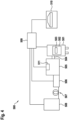
- FIG 4 shows a schematic of a confocal microscope with typical components.
- 500 denotes the overall system.
- the confocal scanning and detection unit is denoted by 505.
- the associated illumination device is denoted by 506.
- the 508 is a laser light source that is connected to the illumination device 506 via an illumination fiber 507. If desired, the laser light is influenced in the illumination device 506 by means of an acousto-optical element.
- a control unit 509 is connected to the individual components 508, 506, 505 and 501 via corresponding connecting lines.
- a computer with control and display programs is designated 510; it is also connected to the control unit 509.
- a classic confocal beam path is arranged within the confocal scanning and detection unit 505, which is constructed in a known manner with a single pinhole and a beam scanner, for example a mirror scanner.
- a beam path is located within the confocal scanning and detection unit 505, in which the sample is illuminated simultaneously with one or more illumination points or with illumination points extending in one direction. Accordingly, the photons to be detected For example, using a geometric arrangement of pinholes.
- the sample 503 to be examined is illuminated via a microscope optics and imaged via the same microscope optics in particular onto a sensor arrangement 511, which, depending on the embodiment of the confocal scanning and detection unit 505, consists of a photomultiplier or an array of photomultipliers.
- a sensor arrangement 511 which, depending on the embodiment of the confocal scanning and detection unit 505, consists of a photomultiplier or an array of photomultipliers.
- the functionality of a Figure 4 The system 500 shown is well known per se and will therefore not be explained here.
Landscapes
- Physics & Mathematics (AREA)
- Nonlinear Science (AREA)
- Optics & Photonics (AREA)
- General Physics & Mathematics (AREA)
- Electromagnetism (AREA)
- Chemical & Material Sciences (AREA)
- Analytical Chemistry (AREA)
- Engineering & Computer Science (AREA)
- Plasma & Fusion (AREA)
- Optical Modulation, Optical Deflection, Nonlinear Optics, Optical Demodulation, Optical Logic Elements (AREA)
- Microscoopes, Condenser (AREA)
Claims (9)
- Méthode de commande d'un élément acousto-optique (200) comprenant un cristal acousto-optique (202) et un transducteur piézoélectrique (201) pour faire vibrer mécaniquement le cristal acousto-optique (202),dans lequel le transducteur piézoélectrique (201) est commandé par un signal de commande (300) ayant au moins une fréquence de commande,l'au moins une fréquence de commande prenant alternativement plusieurs valeurs différentes (f1 , f2 ) autour d'une fréquence centrale pendant un passage d'une onde d'oscillation mécanique (301) à travers le cristal acousto-optique (202), de sorte qu'un réseau généré par des variations de densité dans le cristal acousto-optique (202) présente simultanément différentes distances de réseau,ladite au moins une fréquence de commande étant modifiée périodiquement et rapidement de telle sorte qu'il existe toujours plusieurs zones ayant le même espacement de réseau dans le cristal acousto-optique,dans lequel le cristal acousto-optique (202) est irradié par un faisceau lumineux (401),caractérisé en ce que le faisceau lumineux (401) qui est incident dans le cristal acousto-optique (202) rencontre au moins trois fois une zone ayant le même espacement de réseau.
- Méthode selon la revendication 1, dans lequel les multiples valeurs différentes (f1 , f2 ) se trouvent dans une largeur de bande de 50 kHz - 1 MHz autour de la fréquence centrale.
- Méthode selon l'une quelconque des revendications précédentes, dans lequel la pluralité de valeurs différentes (f1 , f2 ) autour de la fréquence centrale comprend un total de trois à dix valeurs.
- Méthode selon l'une quelconque des revendications précédentes, dans lequel la au moins une fréquence de commande est respectivement constante pour au moins une, de préférence pour plusieurs durées d'oscillation complètes de la fréquence de commande.
- Méthode selon l'une quelconque des revendications précédentes, dans lequel le signal de commande (300) présente simultanément plusieurs fréquences de commande qui prennent chacune des valeurs différentes autour d'une fréquence centrale respective.
- Méthode selon l'une des revendications précédentes, dans lequel un tracé de courbe du signal de commande (300) est continu et sans saut
- Ensemble (100) constitué d'au moins un générateur de signaux (101) pour la commande d'un élément acousto-optique (200), qui est adapté pour mettre en oeuvre un méthode selon l'une des revendications précédentes, d'un élément acousto-optique (200) et d'une source de lumière laser (508).
- Ensemble (100) selon la revendication 7, dans lequel l'élément acousto-optique (200) est choisi parmi un filtre accordable acousto-optique, un modulateur acousto-optique, un déflecteur acousto-optique, un séparateur de faisceau acousto-optique et un unificateur de faisceau acousto-optique.
- Microscope (500) avec un ensemble (100) selon la revendication 7 ou 8.
Applications Claiming Priority (1)
| Application Number | Priority Date | Filing Date | Title |
|---|---|---|---|
| DE102018132327.1A DE102018132327B4 (de) | 2018-12-14 | 2018-12-14 | Verfahren und Signalgenerator zum Ansteuern eines akustooptischen Elements sowie Anordnung und Mikroskop mit einem Signalgenerator |
Publications (2)
| Publication Number | Publication Date |
|---|---|
| EP3667390A1 EP3667390A1 (fr) | 2020-06-17 |
| EP3667390B1 true EP3667390B1 (fr) | 2024-07-17 |
Family
ID=68916245
Family Applications (1)
| Application Number | Title | Priority Date | Filing Date |
|---|---|---|---|
| EP19215791.5A Active EP3667390B1 (fr) | 2018-12-14 | 2019-12-12 | Procédé et générateur de signal destinés à entraîner un élément acousto-optique |
Country Status (5)
| Country | Link |
|---|---|
| US (1) | US11686994B2 (fr) |
| EP (1) | EP3667390B1 (fr) |
| JP (1) | JP7146730B2 (fr) |
| CN (1) | CN111327299B (fr) |
| DE (1) | DE102018132327B4 (fr) |
Families Citing this family (1)
| Publication number | Priority date | Publication date | Assignee | Title |
|---|---|---|---|---|
| DE102024128663A1 (de) * | 2024-10-02 | 2026-04-02 | Abberior Instruments Gmbh | Scanvorrichtung, lichtmikroskop und scanverfahren |
Citations (1)
| Publication number | Priority date | Publication date | Assignee | Title |
|---|---|---|---|---|
| JP2000149337A (ja) * | 1998-09-11 | 2000-05-30 | Ricoh Co Ltd | 光ディスク原盤露光装置 |
Family Cites Families (18)
| Publication number | Priority date | Publication date | Assignee | Title |
|---|---|---|---|---|
| US3531184A (en) * | 1968-06-17 | 1970-09-29 | Zenith Radio Corp | Monochromatic light beam deflection apparatus having two trains of frequency scanned acoustic waves for effecting bragg diffraction |
| US3783185A (en) | 1972-01-28 | 1974-01-01 | Eastman Kodak Co | Multi-color acoustooptic modulator |
| US3935566A (en) | 1973-10-26 | 1976-01-27 | Zenith Radio Corporation | Multiple-channel information translation system and method |
| FR2751095B1 (fr) | 1996-07-09 | 1998-10-30 | Thomson Csf | Dispositif de controle d'impulsions lumineuses par un dispositif programmable acousto-optique |
| US6154307A (en) | 1998-09-18 | 2000-11-28 | United Technologies Corporation | Method and apparatus to diffract multiple beams |
| GB2427034A (en) * | 2005-06-17 | 2006-12-13 | Thales Holdings Uk Plc | Acousto-optic deflection |
| CN100494887C (zh) | 2006-05-22 | 2009-06-03 | 北京航空航天大学 | 基于声光偏转器的正弦条纹结构光投射装置 |
| GB0617945D0 (en) * | 2006-09-12 | 2006-10-18 | Ucl Business Plc | Imaging apparatus and methods |
| US8681412B2 (en) | 2010-06-09 | 2014-03-25 | Leica Microsystems Cms Gmbh | Acousto-optical system, microscope and method of use of the acousto-optical system |
| GB201106787D0 (en) * | 2011-04-20 | 2011-06-01 | Ucl Business Plc | Methods and apparatus to control acousto-optic deflectors |
| CN102299472B (zh) * | 2011-07-12 | 2012-11-21 | 天津奇谱光电技术有限公司 | 光频率精密可调谐激光器 |
| DE102013201968B4 (de) * | 2013-02-07 | 2014-08-28 | BLZ Bayerisches Laserzentrum Gemeinnützige Forschungsgesellschaft mbH | Vorrichtung zur akustooptischen Umformung periodisch gepulster, elektromagnetischer Strahlung |
| DE102013227103B4 (de) * | 2013-09-03 | 2018-05-30 | Leica Microsystems Cms Gmbh | Mikroskop mit einer akustooptischen Vorrichtung |
| EP3145668A4 (fr) | 2014-05-22 | 2018-01-17 | Intel Corporation | Déflecteur acousto-optique à transducteurs multiples pour orientation de faisceau optique |
| US20190339500A1 (en) | 2016-05-31 | 2019-11-07 | Leica Microsystems Cms Gmbh | Optical arrangement for pulsed illumination, method for pulsed illumination and microscope |
| US12468186B2 (en) | 2017-04-25 | 2025-11-11 | Leica Microsystems Cms Gmbh | Method and signal generator for controlling an acousto-optic element |
| CN207217996U (zh) * | 2017-09-28 | 2018-04-10 | 上海濠润电子科技有限公司 | 一种新型声光晶体稳定激光器功率的装置 |
| DE102017223759B3 (de) | 2017-12-22 | 2018-11-22 | Leica Microsystems Cms Gmbh | Verfahren und Signalgenerator zum Ansteuern eines akustooptischen Elements, Mikroskop mit einer Anordnung, bestehend aus dem Signalgenerator und einem akustooptischen Element |
-
2018
- 2018-12-14 DE DE102018132327.1A patent/DE102018132327B4/de active Active
-
2019
- 2019-12-12 EP EP19215791.5A patent/EP3667390B1/fr active Active
- 2019-12-12 US US16/711,483 patent/US11686994B2/en active Active
- 2019-12-13 CN CN201911283769.8A patent/CN111327299B/zh active Active
- 2019-12-13 JP JP2019225433A patent/JP7146730B2/ja active Active
Patent Citations (1)
| Publication number | Priority date | Publication date | Assignee | Title |
|---|---|---|---|---|
| JP2000149337A (ja) * | 1998-09-11 | 2000-05-30 | Ricoh Co Ltd | 光ディスク原盤露光装置 |
Also Published As
| Publication number | Publication date |
|---|---|
| US11686994B2 (en) | 2023-06-27 |
| DE102018132327A1 (de) | 2020-06-18 |
| EP3667390A1 (fr) | 2020-06-17 |
| CN111327299B (zh) | 2023-09-01 |
| US20200192182A1 (en) | 2020-06-18 |
| DE102018132327B4 (de) | 2021-02-25 |
| JP7146730B2 (ja) | 2022-10-04 |
| CN111327299A (zh) | 2020-06-23 |
| JP2020095273A (ja) | 2020-06-18 |
Similar Documents
| Publication | Publication Date | Title |
|---|---|---|
| DE69115716T2 (de) | Vorrichtung zum eingravieren mit einem laserstrahl | |
| EP3042232B1 (fr) | Microscope à balayage et séparateur de faisceaux principaux pour microscope à balayage | |
| EP3042233B1 (fr) | Microscope doté d'un dispostiif acousto-optique | |
| WO2009060027A1 (fr) | Dispositif et procédé pour la commande d'un composant acousto-optique | |
| EP2195612A2 (fr) | Mesure en microscopie à fluorescence d'un échantillon avec des lignes de stokes décalées vers le rouge | |
| DE2901155A1 (de) | Anordnung zum uebertragen gepulster strahlung | |
| EP2095179B1 (fr) | Elément de construction acousto-optique | |
| DE602004007319T2 (de) | Schnelles multispektrales konfokales Rastermikroskop | |
| DE102015104084A1 (de) | Reduktion der Pulsrepetitionsfrequenz eines gepulsten Lasersystems | |
| EP3667390B1 (fr) | Procédé et générateur de signal destinés à entraîner un élément acousto-optique | |
| EP1920387B1 (fr) | Dispositif pour diviser et moduler optiquement un rayonnement electromagnetique | |
| CH644053A5 (de) | Verfahren und vorrichtung zur bildung mehrerer im abstand angeordneter reihen von im abstand angeordneten gleichfoermigen perforationen. | |
| EP3602189B1 (fr) | Procédé et générateur de signal pour commander un élément acousto-optique | |
| DE102021128556A1 (de) | STED-Mikroskop | |
| DE102006040843B4 (de) | Vorrichtung zur optischen Aufspaltung und Modulation von elektromagnetischer Strahlung | |
| EP3465317A1 (fr) | Disposition optique pour l'éclairage pulsé, procédé pour l'éclairage pulsé et microscope | |
| EP3704529B1 (fr) | Procédé et dispositif de balayage d'un échantillon | |
| EP1211553B1 (fr) | Procédé et dispositif pour la modulation de lumière non polarisée | |
| DE102022104988A1 (de) | Vorrichtung mit einem Operationsmikroskop | |
| DE3605468A1 (de) | Farbstofflaser |
Legal Events
| Date | Code | Title | Description |
|---|---|---|---|
| PUAI | Public reference made under article 153(3) epc to a published international application that has entered the european phase |
Free format text: ORIGINAL CODE: 0009012 |
|
| STAA | Information on the status of an ep patent application or granted ep patent |
Free format text: STATUS: THE APPLICATION HAS BEEN PUBLISHED |
|
| AK | Designated contracting states |
Kind code of ref document: A1 Designated state(s): AL AT BE BG CH CY CZ DE DK EE ES FI FR GB GR HR HU IE IS IT LI LT LU LV MC MK MT NL NO PL PT RO RS SE SI SK SM TR |
|
| STAA | Information on the status of an ep patent application or granted ep patent |
Free format text: STATUS: REQUEST FOR EXAMINATION WAS MADE |
|
| 17P | Request for examination filed |
Effective date: 20201216 |
|
| RBV | Designated contracting states (corrected) |
Designated state(s): AL AT BE BG CH CY CZ DE DK EE ES FI FR GB GR HR HU IE IS IT LI LT LU LV MC MK MT NL NO PL PT RO RS SE SI SK SM TR |
|
| STAA | Information on the status of an ep patent application or granted ep patent |
Free format text: STATUS: EXAMINATION IS IN PROGRESS |
|
| 17Q | First examination report despatched |
Effective date: 20220214 |
|
| P01 | Opt-out of the competence of the unified patent court (upc) registered |
Effective date: 20230414 |
|
| GRAP | Despatch of communication of intention to grant a patent |
Free format text: ORIGINAL CODE: EPIDOSNIGR1 |
|
| STAA | Information on the status of an ep patent application or granted ep patent |
Free format text: STATUS: GRANT OF PATENT IS INTENDED |
|
| INTG | Intention to grant announced |
Effective date: 20240209 |
|
| GRAS | Grant fee paid |
Free format text: ORIGINAL CODE: EPIDOSNIGR3 |
|
| GRAA | (expected) grant |
Free format text: ORIGINAL CODE: 0009210 |
|
| STAA | Information on the status of an ep patent application or granted ep patent |
Free format text: STATUS: THE PATENT HAS BEEN GRANTED |
|
| AK | Designated contracting states |
Kind code of ref document: B1 Designated state(s): AL AT BE BG CH CY CZ DE DK EE ES FI FR GB GR HR HU IE IS IT LI LT LU LV MC MK MT NL NO PL PT RO RS SE SI SK SM TR |
|
| REG | Reference to a national code |
Ref country code: CH Ref legal event code: EP |
|
| REG | Reference to a national code |
Ref country code: DE Ref legal event code: R096 Ref document number: 502019011689 Country of ref document: DE |
|
| REG | Reference to a national code |
Ref country code: IE Ref legal event code: FG4D Free format text: LANGUAGE OF EP DOCUMENT: GERMAN |
|
| REG | Reference to a national code |
Ref country code: LT Ref legal event code: MG9D |
|
| REG | Reference to a national code |
Ref country code: NL Ref legal event code: MP Effective date: 20240717 |
|
| PG25 | Lapsed in a contracting state [announced via postgrant information from national office to epo] |
Ref country code: PT Free format text: LAPSE BECAUSE OF FAILURE TO SUBMIT A TRANSLATION OF THE DESCRIPTION OR TO PAY THE FEE WITHIN THE PRESCRIBED TIME-LIMIT Effective date: 20241118 |
|
| PG25 | Lapsed in a contracting state [announced via postgrant information from national office to epo] |
Ref country code: NL Free format text: LAPSE BECAUSE OF FAILURE TO SUBMIT A TRANSLATION OF THE DESCRIPTION OR TO PAY THE FEE WITHIN THE PRESCRIBED TIME-LIMIT Effective date: 20240717 |
|
| PG25 | Lapsed in a contracting state [announced via postgrant information from national office to epo] |
Ref country code: PT Free format text: LAPSE BECAUSE OF FAILURE TO SUBMIT A TRANSLATION OF THE DESCRIPTION OR TO PAY THE FEE WITHIN THE PRESCRIBED TIME-LIMIT Effective date: 20241118 Ref country code: NL Free format text: LAPSE BECAUSE OF FAILURE TO SUBMIT A TRANSLATION OF THE DESCRIPTION OR TO PAY THE FEE WITHIN THE PRESCRIBED TIME-LIMIT Effective date: 20240717 |
|
| PG25 | Lapsed in a contracting state [announced via postgrant information from national office to epo] |
Ref country code: NO Free format text: LAPSE BECAUSE OF FAILURE TO SUBMIT A TRANSLATION OF THE DESCRIPTION OR TO PAY THE FEE WITHIN THE PRESCRIBED TIME-LIMIT Effective date: 20241017 |
|
| PG25 | Lapsed in a contracting state [announced via postgrant information from national office to epo] |
Ref country code: GR Free format text: LAPSE BECAUSE OF FAILURE TO SUBMIT A TRANSLATION OF THE DESCRIPTION OR TO PAY THE FEE WITHIN THE PRESCRIBED TIME-LIMIT Effective date: 20241018 Ref country code: FI Free format text: LAPSE BECAUSE OF FAILURE TO SUBMIT A TRANSLATION OF THE DESCRIPTION OR TO PAY THE FEE WITHIN THE PRESCRIBED TIME-LIMIT Effective date: 20240717 Ref country code: PL Free format text: LAPSE BECAUSE OF FAILURE TO SUBMIT A TRANSLATION OF THE DESCRIPTION OR TO PAY THE FEE WITHIN THE PRESCRIBED TIME-LIMIT Effective date: 20240717 |
|
| PG25 | Lapsed in a contracting state [announced via postgrant information from national office to epo] |
Ref country code: BG Free format text: LAPSE BECAUSE OF FAILURE TO SUBMIT A TRANSLATION OF THE DESCRIPTION OR TO PAY THE FEE WITHIN THE PRESCRIBED TIME-LIMIT Effective date: 20240717 |
|
| PG25 | Lapsed in a contracting state [announced via postgrant information from national office to epo] |
Ref country code: LV Free format text: LAPSE BECAUSE OF FAILURE TO SUBMIT A TRANSLATION OF THE DESCRIPTION OR TO PAY THE FEE WITHIN THE PRESCRIBED TIME-LIMIT Effective date: 20240717 |
|
| PG25 | Lapsed in a contracting state [announced via postgrant information from national office to epo] |
Ref country code: IS Free format text: LAPSE BECAUSE OF FAILURE TO SUBMIT A TRANSLATION OF THE DESCRIPTION OR TO PAY THE FEE WITHIN THE PRESCRIBED TIME-LIMIT Effective date: 20241117 |
|
| PG25 | Lapsed in a contracting state [announced via postgrant information from national office to epo] |
Ref country code: HR Free format text: LAPSE BECAUSE OF FAILURE TO SUBMIT A TRANSLATION OF THE DESCRIPTION OR TO PAY THE FEE WITHIN THE PRESCRIBED TIME-LIMIT Effective date: 20240717 |
|
| PG25 | Lapsed in a contracting state [announced via postgrant information from national office to epo] |
Ref country code: RS Free format text: LAPSE BECAUSE OF FAILURE TO SUBMIT A TRANSLATION OF THE DESCRIPTION OR TO PAY THE FEE WITHIN THE PRESCRIBED TIME-LIMIT Effective date: 20241017 Ref country code: ES Free format text: LAPSE BECAUSE OF FAILURE TO SUBMIT A TRANSLATION OF THE DESCRIPTION OR TO PAY THE FEE WITHIN THE PRESCRIBED TIME-LIMIT Effective date: 20240717 |
|
| PG25 | Lapsed in a contracting state [announced via postgrant information from national office to epo] |
Ref country code: RS Free format text: LAPSE BECAUSE OF FAILURE TO SUBMIT A TRANSLATION OF THE DESCRIPTION OR TO PAY THE FEE WITHIN THE PRESCRIBED TIME-LIMIT Effective date: 20241017 Ref country code: PL Free format text: LAPSE BECAUSE OF FAILURE TO SUBMIT A TRANSLATION OF THE DESCRIPTION OR TO PAY THE FEE WITHIN THE PRESCRIBED TIME-LIMIT Effective date: 20240717 Ref country code: NO Free format text: LAPSE BECAUSE OF FAILURE TO SUBMIT A TRANSLATION OF THE DESCRIPTION OR TO PAY THE FEE WITHIN THE PRESCRIBED TIME-LIMIT Effective date: 20241017 Ref country code: LV Free format text: LAPSE BECAUSE OF FAILURE TO SUBMIT A TRANSLATION OF THE DESCRIPTION OR TO PAY THE FEE WITHIN THE PRESCRIBED TIME-LIMIT Effective date: 20240717 Ref country code: IS Free format text: LAPSE BECAUSE OF FAILURE TO SUBMIT A TRANSLATION OF THE DESCRIPTION OR TO PAY THE FEE WITHIN THE PRESCRIBED TIME-LIMIT Effective date: 20241117 Ref country code: HR Free format text: LAPSE BECAUSE OF FAILURE TO SUBMIT A TRANSLATION OF THE DESCRIPTION OR TO PAY THE FEE WITHIN THE PRESCRIBED TIME-LIMIT Effective date: 20240717 Ref country code: GR Free format text: LAPSE BECAUSE OF FAILURE TO SUBMIT A TRANSLATION OF THE DESCRIPTION OR TO PAY THE FEE WITHIN THE PRESCRIBED TIME-LIMIT Effective date: 20241018 Ref country code: FI Free format text: LAPSE BECAUSE OF FAILURE TO SUBMIT A TRANSLATION OF THE DESCRIPTION OR TO PAY THE FEE WITHIN THE PRESCRIBED TIME-LIMIT Effective date: 20240717 Ref country code: ES Free format text: LAPSE BECAUSE OF FAILURE TO SUBMIT A TRANSLATION OF THE DESCRIPTION OR TO PAY THE FEE WITHIN THE PRESCRIBED TIME-LIMIT Effective date: 20240717 Ref country code: BG Free format text: LAPSE BECAUSE OF FAILURE TO SUBMIT A TRANSLATION OF THE DESCRIPTION OR TO PAY THE FEE WITHIN THE PRESCRIBED TIME-LIMIT Effective date: 20240717 |
|
| PG25 | Lapsed in a contracting state [announced via postgrant information from national office to epo] |
Ref country code: DK Free format text: LAPSE BECAUSE OF FAILURE TO SUBMIT A TRANSLATION OF THE DESCRIPTION OR TO PAY THE FEE WITHIN THE PRESCRIBED TIME-LIMIT Effective date: 20240717 Ref country code: RO Free format text: LAPSE BECAUSE OF FAILURE TO SUBMIT A TRANSLATION OF THE DESCRIPTION OR TO PAY THE FEE WITHIN THE PRESCRIBED TIME-LIMIT Effective date: 20240717 Ref country code: SM Free format text: LAPSE BECAUSE OF FAILURE TO SUBMIT A TRANSLATION OF THE DESCRIPTION OR TO PAY THE FEE WITHIN THE PRESCRIBED TIME-LIMIT Effective date: 20240717 |
|
| REG | Reference to a national code |
Ref country code: DE Ref legal event code: R097 Ref document number: 502019011689 Country of ref document: DE |
|
| PG25 | Lapsed in a contracting state [announced via postgrant information from national office to epo] |
Ref country code: EE Free format text: LAPSE BECAUSE OF FAILURE TO SUBMIT A TRANSLATION OF THE DESCRIPTION OR TO PAY THE FEE WITHIN THE PRESCRIBED TIME-LIMIT Effective date: 20240717 |
|
| PG25 | Lapsed in a contracting state [announced via postgrant information from national office to epo] |
Ref country code: CZ Free format text: LAPSE BECAUSE OF FAILURE TO SUBMIT A TRANSLATION OF THE DESCRIPTION OR TO PAY THE FEE WITHIN THE PRESCRIBED TIME-LIMIT Effective date: 20240717 |
|
| PG25 | Lapsed in a contracting state [announced via postgrant information from national office to epo] |
Ref country code: SK Free format text: LAPSE BECAUSE OF FAILURE TO SUBMIT A TRANSLATION OF THE DESCRIPTION OR TO PAY THE FEE WITHIN THE PRESCRIBED TIME-LIMIT Effective date: 20240717 |
|
| PLBE | No opposition filed within time limit |
Free format text: ORIGINAL CODE: 0009261 |
|
| STAA | Information on the status of an ep patent application or granted ep patent |
Free format text: STATUS: NO OPPOSITION FILED WITHIN TIME LIMIT |
|
| 26N | No opposition filed |
Effective date: 20250422 |
|
| PG25 | Lapsed in a contracting state [announced via postgrant information from national office to epo] |
Ref country code: MC Free format text: LAPSE BECAUSE OF FAILURE TO SUBMIT A TRANSLATION OF THE DESCRIPTION OR TO PAY THE FEE WITHIN THE PRESCRIBED TIME-LIMIT Effective date: 20240717 |
|
| REG | Reference to a national code |
Ref country code: CH Ref legal event code: PL |
|
| PG25 | Lapsed in a contracting state [announced via postgrant information from national office to epo] |
Ref country code: LU Free format text: LAPSE BECAUSE OF NON-PAYMENT OF DUE FEES Effective date: 20241212 |
|
| PG25 | Lapsed in a contracting state [announced via postgrant information from national office to epo] |
Ref country code: SE Free format text: LAPSE BECAUSE OF FAILURE TO SUBMIT A TRANSLATION OF THE DESCRIPTION OR TO PAY THE FEE WITHIN THE PRESCRIBED TIME-LIMIT Effective date: 20240717 |
|
| REG | Reference to a national code |
Ref country code: BE Ref legal event code: MM Effective date: 20241231 |
|
| PG25 | Lapsed in a contracting state [announced via postgrant information from national office to epo] |
Ref country code: BE Free format text: LAPSE BECAUSE OF NON-PAYMENT OF DUE FEES Effective date: 20241231 |
|
| PG25 | Lapsed in a contracting state [announced via postgrant information from national office to epo] |
Ref country code: CH Free format text: LAPSE BECAUSE OF NON-PAYMENT OF DUE FEES Effective date: 20241231 |
|
| PG25 | Lapsed in a contracting state [announced via postgrant information from national office to epo] |
Ref country code: IE Free format text: LAPSE BECAUSE OF NON-PAYMENT OF DUE FEES Effective date: 20241212 |
|
| PGFP | Annual fee paid to national office [announced via postgrant information from national office to epo] |
Ref country code: GB Payment date: 20251223 Year of fee payment: 7 |
|
| PGFP | Annual fee paid to national office [announced via postgrant information from national office to epo] |
Ref country code: FR Payment date: 20251230 Year of fee payment: 7 |
|
| PG25 | Lapsed in a contracting state [announced via postgrant information from national office to epo] |
Ref country code: IT Free format text: LAPSE BECAUSE OF FAILURE TO SUBMIT A TRANSLATION OF THE DESCRIPTION OR TO PAY THE FEE WITHIN THE PRESCRIBED TIME-LIMIT Effective date: 20240717 |
|
| REG | Reference to a national code |
Ref country code: AT Ref legal event code: MM01 Ref document number: 1704689 Country of ref document: AT Kind code of ref document: T Effective date: 20241212 |
|
| PGFP | Annual fee paid to national office [announced via postgrant information from national office to epo] |
Ref country code: DE Payment date: 20251229 Year of fee payment: 7 |
|
| PG25 | Lapsed in a contracting state [announced via postgrant information from national office to epo] |
Ref country code: AT Free format text: LAPSE BECAUSE OF NON-PAYMENT OF DUE FEES Effective date: 20241212 |