EP3667873A1 - Électronique de la pompe - Google Patents
Électronique de la pompe Download PDFInfo
- Publication number
- EP3667873A1 EP3667873A1 EP18020634.4A EP18020634A EP3667873A1 EP 3667873 A1 EP3667873 A1 EP 3667873A1 EP 18020634 A EP18020634 A EP 18020634A EP 3667873 A1 EP3667873 A1 EP 3667873A1
- Authority
- EP
- European Patent Office
- Prior art keywords
- electronics
- module housing
- circuit board
- components
- pump
- Prior art date
- Legal status (The legal status is an assumption and is not a legal conclusion. Google has not performed a legal analysis and makes no representation as to the accuracy of the status listed.)
- Granted
Links
Images


Classifications
-
- H—ELECTRICITY
- H02—GENERATION; CONVERSION OR DISTRIBUTION OF ELECTRIC POWER
- H02K—DYNAMO-ELECTRIC MACHINES
- H02K5/00—Casings; Enclosures; Supports
- H02K5/04—Casings or enclosures characterised by the shape, form or construction thereof
- H02K5/22—Auxiliary parts of casings not covered by groups H02K5/06-H02K5/20, e.g. shaped to form connection boxes or terminal boxes
- H02K5/225—Terminal boxes or connection arrangements
-
- F—MECHANICAL ENGINEERING; LIGHTING; HEATING; WEAPONS; BLASTING
- F04—POSITIVE - DISPLACEMENT MACHINES FOR LIQUIDS; PUMPS FOR LIQUIDS OR ELASTIC FLUIDS
- F04D—NON-POSITIVE-DISPLACEMENT PUMPS
- F04D13/00—Pumping installations or systems
- F04D13/02—Units comprising pumps and their driving means
- F04D13/06—Units comprising pumps and their driving means the pump being electrically driven
- F04D13/0686—Mechanical details of the pump control unit
-
- F—MECHANICAL ENGINEERING; LIGHTING; HEATING; WEAPONS; BLASTING
- F04—POSITIVE - DISPLACEMENT MACHINES FOR LIQUIDS; PUMPS FOR LIQUIDS OR ELASTIC FLUIDS
- F04D—NON-POSITIVE-DISPLACEMENT PUMPS
- F04D29/00—Details, component parts, or accessories
- F04D29/58—Cooling; Heating; Diminishing heat transfer
- F04D29/5813—Cooling the control unit
-
- H—ELECTRICITY
- H02—GENERATION; CONVERSION OR DISTRIBUTION OF ELECTRIC POWER
- H02K—DYNAMO-ELECTRIC MACHINES
- H02K11/00—Structural association of dynamo-electric machines with electric components or with devices for shielding, monitoring or protection
- H02K11/01—Structural association of dynamo-electric machines with electric components or with devices for shielding, monitoring or protection for shielding from electromagnetic fields, i.e. structural association with shields
- H02K11/014—Shields associated with stationary parts, e.g. stator cores
- H02K11/0141—Shields associated with casings, enclosures or brackets
-
- H—ELECTRICITY
- H02—GENERATION; CONVERSION OR DISTRIBUTION OF ELECTRIC POWER
- H02K—DYNAMO-ELECTRIC MACHINES
- H02K11/00—Structural association of dynamo-electric machines with electric components or with devices for shielding, monitoring or protection
- H02K11/02—Structural association of dynamo-electric machines with electric components or with devices for shielding, monitoring or protection for suppression of electromagnetic interference
-
- H—ELECTRICITY
- H02—GENERATION; CONVERSION OR DISTRIBUTION OF ELECTRIC POWER
- H02K—DYNAMO-ELECTRIC MACHINES
- H02K11/00—Structural association of dynamo-electric machines with electric components or with devices for shielding, monitoring or protection
- H02K11/30—Structural association with control circuits or drive circuits
- H02K11/33—Drive circuits, e.g. power electronics
-
- H—ELECTRICITY
- H02—GENERATION; CONVERSION OR DISTRIBUTION OF ELECTRIC POWER
- H02K—DYNAMO-ELECTRIC MACHINES
- H02K15/00—Processes or apparatus specially adapted for manufacturing, assembling, maintaining or repairing of dynamo-electric machines
- H02K15/14—Casings; Enclosures; Supports
-
- H—ELECTRICITY
- H02—GENERATION; CONVERSION OR DISTRIBUTION OF ELECTRIC POWER
- H02K—DYNAMO-ELECTRIC MACHINES
- H02K7/00—Arrangements for handling mechanical energy structurally associated with dynamo-electric machines, e.g. structural association with mechanical driving motors or auxiliary dynamo-electric machines
- H02K7/14—Structural association with mechanical loads, e.g. with hand-held machine tools or fans
-
- H—ELECTRICITY
- H02—GENERATION; CONVERSION OR DISTRIBUTION OF ELECTRIC POWER
- H02K—DYNAMO-ELECTRIC MACHINES
- H02K9/00—Arrangements for cooling or ventilating
- H02K9/22—Arrangements for cooling or ventilating by solid heat conducting material embedded in, or arranged in contact with, the stator or rotor, e.g. heat bridges
- H02K9/223—Heat bridges
-
- H—ELECTRICITY
- H05—ELECTRIC TECHNIQUES NOT OTHERWISE PROVIDED FOR
- H05K—PRINTED CIRCUITS; CASINGS OR CONSTRUCTIONAL DETAILS OF ELECTRIC APPARATUS; MANUFACTURE OF ASSEMBLAGES OF ELECTRICAL COMPONENTS
- H05K7/00—Constructional details common to different types of electric apparatus
- H05K7/14—Mounting supporting structure in casing or on frame or rack
- H05K7/1422—Printed circuit boards receptacles, e.g. stacked structures, electronic circuit modules or box like frames
- H05K7/1427—Housings
- H05K7/1432—Housings specially adapted for power drive units or power converters
- H05K7/14322—Housings specially adapted for power drive units or power converters wherein the control and power circuits of a power converter are arranged within the same casing
-
- H—ELECTRICITY
- H05—ELECTRIC TECHNIQUES NOT OTHERWISE PROVIDED FOR
- H05K—PRINTED CIRCUITS; CASINGS OR CONSTRUCTIONAL DETAILS OF ELECTRIC APPARATUS; MANUFACTURE OF ASSEMBLAGES OF ELECTRICAL COMPONENTS
- H05K7/00—Constructional details common to different types of electric apparatus
- H05K7/20—Modifications to facilitate cooling, ventilating, or heating
- H05K7/2039—Modifications to facilitate cooling, ventilating, or heating characterised by the heat transfer by conduction from the heat generating element to a dissipating body
- H05K7/20436—Inner thermal coupling elements in heat dissipating housings, e.g. protrusions or depressions integrally formed in the housing
- H05K7/20445—Inner thermal coupling elements in heat dissipating housings, e.g. protrusions or depressions integrally formed in the housing the coupling element being an additional piece, e.g. thermal standoff
- H05K7/20463—Filling compound, e.g. potted resin
-
- H—ELECTRICITY
- H05—ELECTRIC TECHNIQUES NOT OTHERWISE PROVIDED FOR
- H05K—PRINTED CIRCUITS; CASINGS OR CONSTRUCTIONAL DETAILS OF ELECTRIC APPARATUS; MANUFACTURE OF ASSEMBLAGES OF ELECTRICAL COMPONENTS
- H05K9/00—Screening of apparatus or components against electric or magnetic fields
- H05K9/0007—Casings
- H05K9/0047—Casings being rigid plastic containers having conductive particles, fibres or mesh embedded therein
Definitions
- the present invention relates to pump electronics of an electromotively driven centrifugal pump, with an electronics housing, in which control and / or regulating electronics with a frequency converter for regulating the speed of the centrifugal pump is arranged, the control and / or regulating electronics having at least one printed circuit board with electrical and / or has electronic components which comprise at least one inductor and semiconductor switch and are surrounded by an electromagnetic shield.
- Control and / or regulating electronics of speed-controlled centrifugal pumps are complex products today. They have electrical and electronic components such as chokes, diodes, transistors, which on the one hand generate electromagnetic interference and therefore have to be shielded for EMC reasons (electromagnetic compatibility), and on the other hand generate considerable waste heat that must be dissipated so that their performance is not impaired and they do not overheat, at worst they can be destroyed.
- Electromagnetic shields are implemented, for example, in the form of perforated or non-perforated metal sheets that cover the components. Cooling can take place actively via cooling elements such as fans, Peltiers or heat pipes, or passively via cooling elements. Gap-bridging contact pads or thermal paste are generally used for a good thermal connection. Screws and other metallic fastening elements are also required in order to mechanically fasten the components, shields and cooling elements locally and to connect them to one another. At the same time, the electrical connection between the components and other components of the control and / or Control electronics can be realized. A large number of individual development and manufacturing steps are therefore required to develop and manufacture pump electronics.
- a generic pump electronics such that the components, ie at least one choke and semiconductor switch, together with the circuit board in a thermally conductive and electrically insulating potting compound are embedded and together form a potting body which is arranged within the electronics housing, the shield being integrated in the potting body.
- An essential aspect of the invention is the spatial compression of the components that generate heat and interference. This makes the electronics more compact and a high degree of functional integration is achieved.
- the heat dissipation and interference shielding takes place directly at the place where they arise and is therefore particularly effective. It follows from this that the components may generate more electromagnetic interference, so that the number and size of the filter components can be reduced.
- installation space is saved, and on the other hand, the pump electronics can be made more compact.
- waste heat can be absorbed from all sides of the components and effectively dissipated.
- the improved cooling achieved in this way increases the efficiency of the components because they no longer have to be temperature-dependent power limitation. With conventional cooling, this is necessary to avoid overheating, whereby the output is limited when a limit temperature is reached.
- the potting body produced by embedding the components forms an assembly that is arranged within the pump electronics. It is therefore not intended to shed the entire pump electronics. Rather, only those or those components of the control and / or regulating electronics that emit heat and electromagnetic radiation to be dissipated are embedded.
- this relates to the power electronics of the pump electronics, such as components of the frequency converter, which adjusts the speed of the centrifugal pump, and / or the circuit for power factor correction (PFC Power Factor Control), which minimizes the system feedback.
- the semiconductor switches to be embedded can be, for example, those of the rectifier, for example diodes, and / or those of the inverter, for example MOSFETS.
- the choke can be the PFC choke of the PFC circuit.
- one or more semiconductor switches of the PFC circuit can also be embedded.
- it can be provided that one or more sensors are embedded in the casting compound, for example temperature sensors, in order to be able to monitor the temperature in the casting body.
- the potting body can have a cup-shaped module housing which is injection molded from a plastic and within which the components are potted with the potting compound.
- This plastic is preferably thermally conductive.
- the module housing thus forms a container which not only serves as a receptacle for the printed circuit board and its components, but also serves as a casting mold which remains connected to the casting compound and becomes part of the casting body.
- the module housing is manufactured in a first injection molding process, then the components are cast in a second step.
- the potting body may also have a module housing made of a thermally conductive plastic, but this plastic is molded onto the outside of the potting compound.
- the components are thus first embedded in the casting compound, for example by casting them in a mold of a tool, and then the module housing is sprayed around the hardened casting compound.
- This encapsulation can be carried out, for example, with the so-called two-component (2K) injection molding.
- the potting compound is preferably a thermoset.
- thermosets for example in the case of synthetic resins, can be comparatively liquid, so that they can be cast without pressure and do not have to be sprayed with pressure. Even the smallest gaps are filled, so that no air bubbles, which form heat barriers, remain in the sealing compound. To improve this, the casting can be carried out in a vacuum. Air bubbles are thereby driven out of the potting compound.
- the module housing can be made of a thermoplastic.
- a thermoplastic which has an EMC shielding can preferably be used. This means that additional shielding measures can be dispensed with. With the preferred wall thicknesses, a thermoplastic can be used to achieve shorter cycle times in the injection molding process.
- the casting compound is expediently electrically insulating, so that no electrical contact is made between the embedded components and the accessible electrical contact points of the components and printed circuit board do not have to be protected from the casting compound.
- the potting body can be designed without a housing. This means that the outside of the hardened casting compound also forms the outside of the casting body, ie it is exposed.
- the casting body can be produced in a casting mold or injection mold of a corresponding tool by casting or injection molding with the casting compound.
- the potting compound can also preferably be a thermoset here, ideally an electrically insulating plastic or synthetic resin.
- the electromagnetic shielding of the components can be done in different ways.
- the shield can be formed by a metallic fleece.
- the module housing can be molded onto the fleece, so that it rests on the inside or outside of the module housing.
- the fleece thus forms an insert which is inserted into the injection mold (cavity) for the production of the cup-shaped module housing is inserted, which is then filled with the plastic, whereby the plastic wets the fleece and, depending on the arrangement of the fleece, presses against the inner or outer cavity wall by the flow pressure.
- the fleece can be inserted into the module housing before the components are cast, so that it lies between the casting compound and the module housing. It is then pressed against the inner wall of the module housing by casting the components.
- the shielding can be formed by a metallic fleece. This is potted with the potting compound in such a way that it lies on the outside of the potting body.
- the fleece can be placed in the mold or injection mold of the tool, which then fills the mold with the sealing compound, which presses the fleece against the wall of the mold by the flow pressure.
- the shield in particular the fleece
- the shielding can be dispensed with on those surfaces of the module housing which bear against a metallic wall, for example the electronics housing, since this wall already provides a shielding.
- this leads to easier processing of the fleece, since the fleece then does not fold so easily, which in turn improves the process reliability.
- the processing of the fleece is particularly simple in the first variant if it lies folded in the module housing to simulate the shape and size of the interior of the module housing.
- the fleece is dimensionally stable due to the folding and can easily be inserted into the module housing, where it remains in position during the casting. Lateral flaps of surface sections can preferably be used of the fleece overlap other surface sections of the fleece. This has the advantage that no electromagnetic radiation emerges at the edges of the fleece.
- the nonwoven in the embodiment variant in which the nonwoven is injected or overmolded by the plastic of the module housing, the nonwoven can be put on a core forming the cavity in the module housing (internal variant) or inserted into the cavity for forming the module housing (external variant).
- the fleece in the embodiment variant in which the components are cast, the fleece can be inserted into the module housing or into the cavity that delimits the casting space. This is the same with overmolding.
- the shield can be formed by an electrically conductive coating.
- This can e.g. be metallic. It can be applied to the module housing on the inside or outside or to the sealing compound on the outside. The application can take place, for example, by spraying, dipping or depositing the coating on the module housing or the sealing compound.
- the shielding can be formed by conductor tracks, in particular a network of conductor tracks. These can also be applied on the inside or outside of the module housing. The application can take place, for example, with the so-called IMKS process (integrated metal plastic injection molding).
- IMKS process integrated metal plastic injection molding
- the shielding can be formed by a metallic insert.
- the insert can be in the form of a grid, perforated plate, mesh or fabric and in particular be dimensionally stable.
- the insert can be embedded in the plastic forming the module housing, so that it becomes and is in one piece with a module housing.
- the insert can be embedded in the potting compound by potting the components, so that it becomes one piece with the potting compound.
- a section of the insert part from the potting body i.e. protrudes from the module housing or from the sealing compound.
- This section forms a connection lug with which the potting body can be connected electrically or thermally in a conductive manner to a further component of the electronics housing.
- the insert is made of metal, it has a very high coefficient of thermal conductivity so that it can optimally transport the heat out of the casting compound. In this case, the plastic of the module housing need not be thermally conductive.
- the insert is thermally conductively connected, preferably screwed, to a heat sink, in particular to a metallic wall of the electronics housing.
- the insert can be electrically connected to ground via the section.
- the plastic which forms the module housing can contain particles which bring about the electromagnetic shielding.
- These can be steel fibers, for example, or carbon-based fillers (so-called conductivity carbon black).
- the circuit board can preferably be arranged at right angles to an opening in the module housing through which the circuit board is inserted into the module housing.
- the circuit board is thus in the casting direction. Free spaces are formed on both sides of the circuit board, which can be filled easily and completely with the sealing compound.
- the circuit board does not block or hinder the potting compound.
- the choke is ideally formed by a toroidal core choke. This is preferably mounted horizontally on the circuit board so that its diameter runs parallel to the circuit board. The choke is therefore not on the circuit board, which results in a compact design of the potting body. The necessary Dimensions of the potting body are furthermore kept small by the components being arranged on both sides of the printed circuit board.
- the choke can be arranged on a first side of the printed circuit board and the semiconductor switches on the other side of the printed circuit board.
- the potting body In order to achieve particularly good heat dissipation from the potting body, it is advantageous if it rests in a thermally conductive manner on at least one metallic wall of the electronics housing. The wall then serves as a heat sink and absorbs the heat of the potting body, so that the potting body is effectively cooled.
- the printed circuit board can have passage openings for the potting compound to pass through when the components are potted.
- the liquid potting compound can flow through the circuit board from the side to the other side of the circuit board. In the hardened state, the potting compound is therefore also in the passage openings.
- the insert for embedding in the potting compound is held stationary relative to the circuit board and its position and / or orientation during casting or Injection molding of the potting compound does not change, the insert can be held mechanically on the circuit board.
- holding openings can be provided in the printed circuit board, into which the insert part with corresponding fastening sections lies firmly.
- the potting body can also contain molded-in holding elements for the stationary mounting of the printed circuit board in the mold or injection mold of a mold.
- These brackets can, for example, be pin-shaped and extend through holding openings, so that the holding elements protrude on one or on both sides of the printed circuit board, so that the latter is supported on the walls of the mold or injection mold.
- the casting compound it also encloses the holding elements, so that they remain permanently in the casting body.
- EMI Electromagnetic Interference
- these components comprise the choke 6 belonging to the PFC circuit ( Fig. 2 ) and semiconductor switches 7, 8 ( Fig. 6 ) in the form of diodes 7 and transistors 8 (MOSFETS).
- the invention provides that the components 6, 7, 8 together with the printed circuit board 5 are embedded in a thermally conductive casting compound 4 and together form a casting body 3.
- This potting body 3 is arranged within the electronics housing 3 and has an integrated shield 8.
- the potting body 3 thus forms a highly integrated functional assembly which, on the one hand, simplifies the manufacture of the pump electronics and, on the other hand, effects effective cooling and EMI shielding. Due to the full-surface covering of the components 6, 7, 8 by the thermally conductive casting compound, the heat generated is absorbed directly by the casting compound and dissipated by the components. The components are virtually encapsulated by the integrated electromagnetic shielding. Interference is limited to the place of origin and cannot spread to the rest of the pump electronics 1.
- the potting compound 4 is electrically insulating, so that the live parts of the components that are freely accessible before assembly can safely come into contact with the potting compound.
- the potting compound 4 also protects the components from moisture and fixes them in place so that they cannot move as a result of vibrations and shocks, which occur primarily when the pump is being transported to the customer, but also during operation.
- the potting body 3 has a cup-shaped module housing 9, while the potting body 3 in the embodiment variant Fig. 3 is caseless, so that the hardened casting compound is exposed to the outside.
- the module housing 9 is injection molded from a thermally conductive, thermoplastic. It is cuboid in its basic form, but can also be shaped differently. However, it is advantageous if the shape has at least one flat wall in order to be able to place the module housing on a heat sink, the cooling surfaces of which are usually also flat.
- the circuit board 5 provides electrical connections in the form of contact surfaces 17 on this part.
- the connections 17 are comb-like in that there are recesses in the printed circuit board 5 between two adjacent contact surfaces.
- the production of the casting body 3 according to 1 and 2 takes place in such a way that the module housing 9 is first produced in an injection molding machine, preferably from a thermoplastic material, which ideally is also thermally conductive and EMC shielding.
- the circuit board 5 is assembled with the components 6, 7, 8, the inductor 6 being arranged on one side of the circuit board 5 and the diodes 7 and transistors 8 on the other side.
- the choke 6 is designed in the form of a toroidal core coil and lies flat on the circuit board 5, so that a compact arrangement is achieved.
- the assembled circuit board 5 is then inserted through the opening 15 into the module housing 9 and potted therein with the potting compound 4, the potting compound 4 being poured into the module housing 9 without pressure through the opening 15.
- the module housing 9 thus also forms the casting mold for the casting compound.
- the production of the casting body 3 according to Fig. 3 takes place in such a way that the printed circuit board 5 is first assembled with the components 6, 7, 8, the choke 6 being arranged on one side and the diodes 7 and transistors 8 on the other side of the printed circuit board 5.
- the choke 6 is also designed here in the form of a toroidal core coil and lies flat on the printed circuit board 5, so that a compact arrangement is achieved.
- the assembled circuit board 5 inserted into the mold or injection mold of a casting or injection molding tool, which then fills the casting compound 4 without pressure or with an appropriate injection pressure, depending on the viscosity of the casting compound 4, into the casting mold or injection mold.
- the casting or injection mold also has a cuboid shape here, so that the potting body 3 ultimately also becomes cuboid.
- the sprayed-on plastic can be a thermoplastic, preferably with thermal conductivity.
- a potting body 3 with a housing can also be produced in such a way that, as described, the potting body 3 is first produced in the mold or injection mold of a casting or injection molding tool and then after the potting compound 4 has solidified, another plastic around the potting compound 4 is injected, which forms the module housing 9. This can be achieved with the so-called two-component injection molding process (two-component).
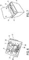
- FIGS 4 to 7 show a further embodiment of the casting body 3, in which the shield is formed by a metallic fleece 10.
- the fleece 10 is inserted into the module housing 9 in a folded form before the components 6, 7, 8 are cast, as shown in FIG Fig. 5 can be seen.
- the potting compound 4 presses the fleece 10 against the inside of the module housing 9, so that after the potting compound it lies between the potting compound 4 and the module housing 9, but is wetted by the potting compound 4.
- the fleece 10 it is possible to insert the fleece 10 into the injection mold for the module housing 9 and to spray the module housing 9 onto the fleece 10.
- the fleece can rest on the inside or outside of the module housing 9. If it lies on the inside, the fleece 10 in the final state of the potting body 3 is also arranged between the potting compound 4 and the module housing 9, but the fleece 10 is not wetted by the potting compound 4, but by the plastic of the module housing 9.
- the fleece 10 into the casting or injection mold for producing the housing-free potting body 3. Since the fleece 10 is not or hardly penetrated by the potting compound 4, it is pressed against the wall of the mold and then lies on the potting body 3 on the outside in the hardened state of the potting compound 4.
- Fig. 4 shows the metallic fleece 10 as a flat structure, which is cut according to the inner shape of the module housing. It is formed from coherent surface sections 11, each of which corresponds in size and shape to an inner wall of the module housing 9 and merges into one another at a fold on which the fleece 10 is later folded. A further surface section 11 extends from a central surface section 11 a, which comes to rest on the bottom of the module housing 9, on each of the four sides 9 lying state overlap the adjacent surface sections 11. This prevents electromagnetic radiation from emerging at the side edges of the casting body 3. A surface section 11 is adjoined by a further surface section 19 which, as intended, protrudes from the module housing 9, as in FIG Fig. 5 can be seen.
- This protruding surface section 19 can be folded over after the insertion of the printed circuit board 5 together with the components 6, 7, 8 in order to at least partially close the opening 15 of the module housing, so that no electromagnetic radiation emerges from the opening 15. The folding takes place after the components 6, 7, 8 are cast. In the same way, a tab 12 can protrude from the module housing 9 on the opposite side, which tab is also intended to close part of the opening 15.
- Fig. 6 shows the circuit board 5 equipped with the components 7, 8, which is to be inserted into the module housing 9, as is also the case with the Figures 1 and 2 the case is.
- the circuit board 5 comprises a printed circuit (PCB) with conductor tracks which connect at least some of the components to one another.
- PCB printed circuit
- Holding elements 21 for holding the throttle 9 engage in corresponding holding openings by means of locking lugs.
- the printed circuit board 5 is inserted in the module housing 9 at right angles to the opening 15, the edge-side connection contacts 17 protruding from the module housing 9. In this state, the circuit board 5 and the components 6, 7, 8 are cast.
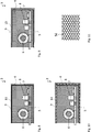
- FIGS 8 to 16 show different implementation variants for electromagnetic shielding using a potting body, which is only shown as a schematic diagram.
- a choke 6 and semiconductor components 7, 8, in particular semiconductor switches, are arranged here on a printed circuit board 5.
- Fig. 8 corresponds essentially to that in the Figures 5 and 6 shown embodiment variant, in which the shielding is formed by a metallic fleece 10.
- the potting body 3 is here provided with a module housing 9, the fleece 10 being located between the potting compound 4 and the module housing 9.
- the fleece 10 can either have become an integral part of the manufacture of the module housing 9 or, as in FIG Fig. 5 , have been embedded in the casting body 3 when the components have been cast.
- the potting compound 4 is made of an electrically insulating, thermally conductive plastic polymer, in particular a thermoset.
- the plastic of the module housing 9 is also thermally conductive, in particular a thermoplastic.
- the fleece 10 can rest on the outside of the module housing 9.
- the shield is formed by an electrically conductive, in particular metallic coating 13 on the inside of the module housing 9. Alternatively, it can also be applied to the outside of the module housing 9. Otherwise, this variant corresponds to that in Fig. 8 .
- the shielding is formed by a metallic insert 14 which is embedded in the plastic of the module housing 9. It is only in this plastic, so it does not extend into the interior of the module housing 9, so that it is not in contact with the sealing compound 4. Nevertheless, this can also be possible in an embodiment variant, so that it is partially embedded in the plastic of the module housing 9 and partially in the casting compound.
- the insert 14 can be, for example, a grid, a perforated plate, a net or a fabric. It is preferably dimensionally stable and has meshes through which the plastic can penetrate.
- Fig. 11 shows an example of the insert 14 in the form of a honeycomb network.
- Fig. 12 shows a housing-free potting body 3 according to Fig. 3 , which, however, is provided on the outside with a fleece 10 as an electromagnetic shield.
- Fig. 13 also shows a housing-free potting body 3 according to Fig. 3 , which is provided here on the outside with an electrically conductive, in particular metallic coating 13 as an electromagnetic shield.
- Fig. 14 shows a potting body 3 with module housing 9 which has particles which cause electromagnetic shielding.
- the potting compound 4 consists of an electrically insulating and thermally conductive plastic polymer, in particular a thermoset. However, it has no shielding properties.
- the plastic of the module housing 9 is thermally conductive, in particular a thermoplastic, in addition to the shielding property.
- Fig. 15 shows a housing-free potting body 3 according to Fig. 3 , in which the shield is also formed by a metallic insert 14. This is embedded in the sealing compound 4, as is also the case in Fig. 1 is the case in which the potting body 3 has a module housing 9.
- the insert 14 can be, for example, a grid, a perforated plate, a net or a fabric. It is preferably dimensionally stable and has meshes through which the sealing compound 4 can penetrate.
- the insert 14 can also form here.
- Fig. 16 shows a module housing 9, in which conductor tracks are applied on the outside as a shield. These form a network-like structure.
- the conductor tracks can be manufactured using the so-called IMKS technology. Alternatively, these conductor tracks can also be applied to the inside of the module housing 9. Further alternatively, the conductor tracks can be applied on the outside to the housing-free casting compound 4.
- the conductor tracks on the module housing 9 or on the potting compound can also be used for heat conduction.
- the insert 14 protrudes from the casting body 3 with a section 16, as shown in FIG Fig. 1 the case is.
- the insert 14 serves both to conduct the heat out of the potting body 3 and also as a mechanical fastening option and electrical connection option.
- the insert 14 can be connected to ground. This can preferably be done by screwing to the wall 18 of the electronics housing 2, which then serves not only as a heat sink, but also as grounding.
- the printed circuit board 5 with contacts 17, such as contact pads, protrude from the sealing compound 4 or the sealing body 3.
- contacts such as pin-shaped contacts are used, which protrude from the sealing compound 4 and contact the circuit board 5, while the circuit board 5 is completely potted. So that the contacts are not wetted by the plastic, it is advantageous to seal them with a sealing element during the casting or overmolding of the components 6, 7, 8.
- the potting compound 4 should be injected in such a way that the spray jet is not directed directly at the components 6, 7, 8.
- the spray jet is suitably directed onto the printed circuit board or the cavity or module housing inner wall.
- the present invention provides an electromagnetically shielded, thermally conductive, polytronic assembly with integrated coils, winding materials, Semiconductors and / or sensors, in particular with components of the power electronics of a pump, such as the PFC circuit, are provided.
- the assembly can include the PFC choke and semiconductor switch on a printed circuit board, coated with thermally conductive casting compound, and with integrated EMC shielding, which may also be used for heat dissipation, for example, by the shield being an insert (perforated plate) with a flag to the outside . This results in fewer assembly steps.
- a prefabrication of the throttle 6 is omitted, so that the production is simplified.
- Design loops for EMC-compliant design can be saved. Additional components, some of which would be necessary for an EMC-compliant design, can be saved.
- Another advantage is that the solution according to the invention is scalable, so that more or fewer components can be accommodated in the casting body 3 as required.
Landscapes
- Engineering & Computer Science (AREA)
- Power Engineering (AREA)
- Microelectronics & Electronic Packaging (AREA)
- Physics & Mathematics (AREA)
- Electromagnetism (AREA)
- Thermal Sciences (AREA)
- Mechanical Engineering (AREA)
- General Engineering & Computer Science (AREA)
- Manufacturing & Machinery (AREA)
- Shielding Devices Or Components To Electric Or Magnetic Fields (AREA)
Priority Applications (1)
| Application Number | Priority Date | Filing Date | Title |
|---|---|---|---|
| EP18020634.4A EP3667873B1 (fr) | 2018-12-10 | 2018-12-10 | Électronique de la pompe |
Applications Claiming Priority (1)
| Application Number | Priority Date | Filing Date | Title |
|---|---|---|---|
| EP18020634.4A EP3667873B1 (fr) | 2018-12-10 | 2018-12-10 | Électronique de la pompe |
Publications (2)
| Publication Number | Publication Date |
|---|---|
| EP3667873A1 true EP3667873A1 (fr) | 2020-06-17 |
| EP3667873B1 EP3667873B1 (fr) | 2022-03-23 |
Family
ID=64899152
Family Applications (1)
| Application Number | Title | Priority Date | Filing Date |
|---|---|---|---|
| EP18020634.4A Active EP3667873B1 (fr) | 2018-12-10 | 2018-12-10 | Électronique de la pompe |
Country Status (1)
| Country | Link |
|---|---|
| EP (1) | EP3667873B1 (fr) |
Cited By (3)
| Publication number | Priority date | Publication date | Assignee | Title |
|---|---|---|---|---|
| LU500868B1 (de) * | 2021-11-17 | 2023-05-23 | Wilo Se | Kreiselpumpe |
| LU102976B1 (de) * | 2022-07-05 | 2024-01-09 | Wilo Se | Kreiselpumpe mit einem Gehäuse |
| FR3149464A1 (fr) * | 2023-06-01 | 2024-12-06 | Psa Automobiles Sa | Boîtier de reception pour batterie ou carte electronique dans un vehicule automobile |
Families Citing this family (1)
| Publication number | Priority date | Publication date | Assignee | Title |
|---|---|---|---|---|
| DE102024116175A1 (de) * | 2024-06-10 | 2025-12-11 | Semikron Danfoss GmbH | Verfahren zur Herstellung eines Rahmens eines Leistungsmoduls, Rahmen und Leistungsmodul |
Citations (6)
| Publication number | Priority date | Publication date | Assignee | Title |
|---|---|---|---|---|
| US5285619A (en) * | 1992-10-06 | 1994-02-15 | Williams International Corporation | Self tooling, molded electronics packaging |
| EP1643818A1 (fr) * | 2003-07-03 | 2006-04-05 | Hitachi, Ltd. | Module et procede de fabrication de celui-ci |
| US20100176534A1 (en) * | 2009-01-13 | 2010-07-15 | Enphase Energy, Inc. | Method and apparatus for potting an electronic device |
| US20120057388A1 (en) * | 2011-03-22 | 2012-03-08 | Paul Garrity | Solar Photovoltaic Inverters |
| EP2618004A1 (fr) * | 2010-09-29 | 2013-07-24 | Aisin Seiki Kabushiki Kaisha | Pompe électrique |
| US20170027058A1 (en) * | 2015-07-21 | 2017-01-26 | Apple Inc. | Packaged Electrical Components With Supplemental Conductive Structures |
Family Cites Families (3)
| Publication number | Priority date | Publication date | Assignee | Title |
|---|---|---|---|---|
| KR20150023710A (ko) * | 2012-06-15 | 2015-03-05 | 가부시키가이샤 가네카 | 방열 구조체 |
| EP2750267B1 (fr) * | 2012-12-27 | 2018-01-24 | Grundfos Holding A/S | Groupe motopompe |
| EP2905888A1 (fr) * | 2014-02-05 | 2015-08-12 | Grundfos Holding A/S | Onduleur |
-
2018
- 2018-12-10 EP EP18020634.4A patent/EP3667873B1/fr active Active
Patent Citations (6)
| Publication number | Priority date | Publication date | Assignee | Title |
|---|---|---|---|---|
| US5285619A (en) * | 1992-10-06 | 1994-02-15 | Williams International Corporation | Self tooling, molded electronics packaging |
| EP1643818A1 (fr) * | 2003-07-03 | 2006-04-05 | Hitachi, Ltd. | Module et procede de fabrication de celui-ci |
| US20100176534A1 (en) * | 2009-01-13 | 2010-07-15 | Enphase Energy, Inc. | Method and apparatus for potting an electronic device |
| EP2618004A1 (fr) * | 2010-09-29 | 2013-07-24 | Aisin Seiki Kabushiki Kaisha | Pompe électrique |
| US20120057388A1 (en) * | 2011-03-22 | 2012-03-08 | Paul Garrity | Solar Photovoltaic Inverters |
| US20170027058A1 (en) * | 2015-07-21 | 2017-01-26 | Apple Inc. | Packaged Electrical Components With Supplemental Conductive Structures |
Cited By (4)
| Publication number | Priority date | Publication date | Assignee | Title |
|---|---|---|---|---|
| LU500868B1 (de) * | 2021-11-17 | 2023-05-23 | Wilo Se | Kreiselpumpe |
| LU102976B1 (de) * | 2022-07-05 | 2024-01-09 | Wilo Se | Kreiselpumpe mit einem Gehäuse |
| EP4303444A1 (fr) * | 2022-07-05 | 2024-01-10 | Wilo Se | Pompe centrifuge avec carter |
| FR3149464A1 (fr) * | 2023-06-01 | 2024-12-06 | Psa Automobiles Sa | Boîtier de reception pour batterie ou carte electronique dans un vehicule automobile |
Also Published As
| Publication number | Publication date |
|---|---|
| EP3667873B1 (fr) | 2022-03-23 |
Similar Documents
| Publication | Publication Date | Title |
|---|---|---|
| DE112015003987B4 (de) | Schaltungsbaugruppe, elektrischer Verteiler und Herstellungsverfahren für eine Schaltungsbaugruppe | |
| DE102014112330B4 (de) | Überspritzte Substrat-Chip-Anordnung mit Wärmesenke, Motorsteuermodul und zugehöriges Herstellverfahren | |
| EP3667873B1 (fr) | Électronique de la pompe | |
| EP2166230B1 (fr) | Groupe motopompe | |
| DE112015005727T5 (de) | Schaltungsanordnung und elektrischer Verteiler | |
| DE102015001148B4 (de) | Anordnung und Verfahren zur elektromagnetischen Abschirmung | |
| DE112015004024T5 (de) | Schaltungsbaugruppe und elektrischer Verteiler | |
| WO2012104017A1 (fr) | Appareil électrique | |
| DE102008023711A1 (de) | Halbleitermodul und Verfahren zur Herstellung eines Halbleitermoduls | |
| EP2607707A1 (fr) | Moteur électrique | |
| WO2012000736A1 (fr) | Module d'appareil de commande | |
| DE102016208029A1 (de) | Halbleitervorrichtung | |
| DE102013002629A1 (de) | Deckelelement und Gehäusevorrichtung zur Verwendung des Deckelelements | |
| EP3479663B1 (fr) | Unité appareil de commande, en particulier pour un véhicule automobile | |
| EP2607708B1 (fr) | Moteur électrique | |
| DE102014209185A1 (de) | Elektronikmodul für eine Zündeinheit | |
| DE4435510C1 (de) | Frequenzumrichtergespeistes Pumpenaggregat | |
| WO2021105028A1 (fr) | Module de puissance à semi-conducteurs de puissance logés pour l'alimentation électrique commandable d'un consommateur, et son procédé de production | |
| WO2011141234A1 (fr) | Dispositif électronique de puissance | |
| EP4002968B1 (fr) | Onduleur et son procédé de fabrication | |
| DE102011075308A1 (de) | Elektronische Schaltungsanordnung | |
| DE19904279B4 (de) | Halbleitervorrichtung | |
| WO2006024626A2 (fr) | Module electrique | |
| DE102017220211B4 (de) | Halbleitervorrichtung und verfahren zur fertigung derselben | |
| WO2022228619A1 (fr) | Dispositif de filtre cem ayant une structure conductrice montée dans un boîtier ; et module électronique de puissance |
Legal Events
| Date | Code | Title | Description |
|---|---|---|---|
| STAA | Information on the status of an ep patent application or granted ep patent |
Free format text: STATUS: EXAMINATION IS IN PROGRESS |
|
| PUAI | Public reference made under article 153(3) epc to a published international application that has entered the european phase |
Free format text: ORIGINAL CODE: 0009012 |
|
| 17P | Request for examination filed |
Effective date: 20190611 |
|
| AK | Designated contracting states |
Kind code of ref document: A1 Designated state(s): AL AT BE BG CH CY CZ DE DK EE ES FI FR GB GR HR HU IE IS IT LI LT LU LV MC MK MT NL NO PL PT RO RS SE SI SK SM TR |
|
| AX | Request for extension of the european patent |
Extension state: BA ME |
|
| RIC1 | Information provided on ipc code assigned before grant |
Ipc: F04D 29/58 20060101ALI20200821BHEP Ipc: H02K 15/14 20060101ALI20200821BHEP Ipc: F04D 13/06 20060101ALI20200821BHEP Ipc: H05K 5/00 20060101ALI20200821BHEP Ipc: H02K 11/22 20160101AFI20200821BHEP Ipc: H02K 9/22 20060101ALI20200821BHEP Ipc: H02K 11/33 20160101ALI20200821BHEP Ipc: H05K 9/00 20060101ALI20200821BHEP Ipc: H05K 7/20 20060101ALI20200821BHEP Ipc: H05K 7/14 20060101ALI20200821BHEP Ipc: H02K 5/22 20060101ALI20200821BHEP Ipc: H02K 7/14 20060101ALI20200821BHEP |
|
| GRAP | Despatch of communication of intention to grant a patent |
Free format text: ORIGINAL CODE: EPIDOSNIGR1 |
|
| STAA | Information on the status of an ep patent application or granted ep patent |
Free format text: STATUS: GRANT OF PATENT IS INTENDED |
|
| RIC1 | Information provided on ipc code assigned before grant |
Ipc: H02K 11/02 20160101ALI20211020BHEP Ipc: H02K 11/01 20160101ALI20211020BHEP Ipc: H05K 7/20 20060101ALI20211020BHEP Ipc: F04D 29/58 20060101ALI20211020BHEP Ipc: F04D 13/06 20060101ALI20211020BHEP Ipc: H05K 7/14 20060101ALI20211020BHEP Ipc: H05K 9/00 20060101ALI20211020BHEP Ipc: H02K 11/33 20160101ALI20211020BHEP Ipc: H02K 15/14 20060101ALI20211020BHEP Ipc: H02K 9/22 20060101ALI20211020BHEP Ipc: H02K 7/14 20060101ALI20211020BHEP Ipc: H05K 5/00 20060101ALI20211020BHEP Ipc: H02K 11/22 20160101ALI20211020BHEP Ipc: H01L 23/552 20060101ALI20211020BHEP Ipc: H01L 23/373 20060101ALI20211020BHEP Ipc: H01L 23/31 20060101ALI20211020BHEP Ipc: H02K 5/22 20060101AFI20211020BHEP |
|
| INTG | Intention to grant announced |
Effective date: 20211118 |
|
| GRAS | Grant fee paid |
Free format text: ORIGINAL CODE: EPIDOSNIGR3 |
|
| GRAA | (expected) grant |
Free format text: ORIGINAL CODE: 0009210 |
|
| STAA | Information on the status of an ep patent application or granted ep patent |
Free format text: STATUS: THE PATENT HAS BEEN GRANTED |
|
| AK | Designated contracting states |
Kind code of ref document: B1 Designated state(s): AL AT BE BG CH CY CZ DE DK EE ES FI FR GB GR HR HU IE IS IT LI LT LU LV MC MK MT NL NO PL PT RO RS SE SI SK SM TR |
|
| RAP3 | Party data changed (applicant data changed or rights of an application transferred) |
Owner name: WILO SE |
|
| REG | Reference to a national code |
Ref country code: GB Ref legal event code: FG4D Free format text: NOT ENGLISH |
|
| REG | Reference to a national code |
Ref country code: CH Ref legal event code: EP |
|
| REG | Reference to a national code |
Ref country code: IE Ref legal event code: FG4D Free format text: LANGUAGE OF EP DOCUMENT: GERMAN |
|
| REG | Reference to a national code |
Ref country code: DE Ref legal event code: R096 Ref document number: 502018009145 Country of ref document: DE |
|
| REG | Reference to a national code |
Ref country code: AT Ref legal event code: REF Ref document number: 1478121 Country of ref document: AT Kind code of ref document: T Effective date: 20220415 |
|
| REG | Reference to a national code |
Ref country code: LT Ref legal event code: MG9D |
|
| REG | Reference to a national code |
Ref country code: NL Ref legal event code: MP Effective date: 20220323 |
|
| PG25 | Lapsed in a contracting state [announced via postgrant information from national office to epo] |
Ref country code: SE Free format text: LAPSE BECAUSE OF FAILURE TO SUBMIT A TRANSLATION OF THE DESCRIPTION OR TO PAY THE FEE WITHIN THE PRESCRIBED TIME-LIMIT Effective date: 20220323 Ref country code: RS Free format text: LAPSE BECAUSE OF FAILURE TO SUBMIT A TRANSLATION OF THE DESCRIPTION OR TO PAY THE FEE WITHIN THE PRESCRIBED TIME-LIMIT Effective date: 20220323 Ref country code: NO Free format text: LAPSE BECAUSE OF FAILURE TO SUBMIT A TRANSLATION OF THE DESCRIPTION OR TO PAY THE FEE WITHIN THE PRESCRIBED TIME-LIMIT Effective date: 20220623 Ref country code: LT Free format text: LAPSE BECAUSE OF FAILURE TO SUBMIT A TRANSLATION OF THE DESCRIPTION OR TO PAY THE FEE WITHIN THE PRESCRIBED TIME-LIMIT Effective date: 20220323 Ref country code: HR Free format text: LAPSE BECAUSE OF FAILURE TO SUBMIT A TRANSLATION OF THE DESCRIPTION OR TO PAY THE FEE WITHIN THE PRESCRIBED TIME-LIMIT Effective date: 20220323 Ref country code: BG Free format text: LAPSE BECAUSE OF FAILURE TO SUBMIT A TRANSLATION OF THE DESCRIPTION OR TO PAY THE FEE WITHIN THE PRESCRIBED TIME-LIMIT Effective date: 20220623 |
|
| PG25 | Lapsed in a contracting state [announced via postgrant information from national office to epo] |
Ref country code: LV Free format text: LAPSE BECAUSE OF FAILURE TO SUBMIT A TRANSLATION OF THE DESCRIPTION OR TO PAY THE FEE WITHIN THE PRESCRIBED TIME-LIMIT Effective date: 20220323 Ref country code: GR Free format text: LAPSE BECAUSE OF FAILURE TO SUBMIT A TRANSLATION OF THE DESCRIPTION OR TO PAY THE FEE WITHIN THE PRESCRIBED TIME-LIMIT Effective date: 20220624 Ref country code: FI Free format text: LAPSE BECAUSE OF FAILURE TO SUBMIT A TRANSLATION OF THE DESCRIPTION OR TO PAY THE FEE WITHIN THE PRESCRIBED TIME-LIMIT Effective date: 20220323 |
|
| PG25 | Lapsed in a contracting state [announced via postgrant information from national office to epo] |
Ref country code: NL Free format text: LAPSE BECAUSE OF FAILURE TO SUBMIT A TRANSLATION OF THE DESCRIPTION OR TO PAY THE FEE WITHIN THE PRESCRIBED TIME-LIMIT Effective date: 20220323 |
|
| PG25 | Lapsed in a contracting state [announced via postgrant information from national office to epo] |
Ref country code: SM Free format text: LAPSE BECAUSE OF FAILURE TO SUBMIT A TRANSLATION OF THE DESCRIPTION OR TO PAY THE FEE WITHIN THE PRESCRIBED TIME-LIMIT Effective date: 20220323 Ref country code: SK Free format text: LAPSE BECAUSE OF FAILURE TO SUBMIT A TRANSLATION OF THE DESCRIPTION OR TO PAY THE FEE WITHIN THE PRESCRIBED TIME-LIMIT Effective date: 20220323 Ref country code: RO Free format text: LAPSE BECAUSE OF FAILURE TO SUBMIT A TRANSLATION OF THE DESCRIPTION OR TO PAY THE FEE WITHIN THE PRESCRIBED TIME-LIMIT Effective date: 20220323 Ref country code: PT Free format text: LAPSE BECAUSE OF FAILURE TO SUBMIT A TRANSLATION OF THE DESCRIPTION OR TO PAY THE FEE WITHIN THE PRESCRIBED TIME-LIMIT Effective date: 20220725 Ref country code: ES Free format text: LAPSE BECAUSE OF FAILURE TO SUBMIT A TRANSLATION OF THE DESCRIPTION OR TO PAY THE FEE WITHIN THE PRESCRIBED TIME-LIMIT Effective date: 20220323 Ref country code: EE Free format text: LAPSE BECAUSE OF FAILURE TO SUBMIT A TRANSLATION OF THE DESCRIPTION OR TO PAY THE FEE WITHIN THE PRESCRIBED TIME-LIMIT Effective date: 20220323 Ref country code: CZ Free format text: LAPSE BECAUSE OF FAILURE TO SUBMIT A TRANSLATION OF THE DESCRIPTION OR TO PAY THE FEE WITHIN THE PRESCRIBED TIME-LIMIT Effective date: 20220323 |
|
| PG25 | Lapsed in a contracting state [announced via postgrant information from national office to epo] |
Ref country code: PL Free format text: LAPSE BECAUSE OF FAILURE TO SUBMIT A TRANSLATION OF THE DESCRIPTION OR TO PAY THE FEE WITHIN THE PRESCRIBED TIME-LIMIT Effective date: 20220323 Ref country code: IS Free format text: LAPSE BECAUSE OF FAILURE TO SUBMIT A TRANSLATION OF THE DESCRIPTION OR TO PAY THE FEE WITHIN THE PRESCRIBED TIME-LIMIT Effective date: 20220723 Ref country code: AL Free format text: LAPSE BECAUSE OF FAILURE TO SUBMIT A TRANSLATION OF THE DESCRIPTION OR TO PAY THE FEE WITHIN THE PRESCRIBED TIME-LIMIT Effective date: 20220323 |
|
| REG | Reference to a national code |
Ref country code: DE Ref legal event code: R097 Ref document number: 502018009145 Country of ref document: DE |
|
| PLBE | No opposition filed within time limit |
Free format text: ORIGINAL CODE: 0009261 |
|
| STAA | Information on the status of an ep patent application or granted ep patent |
Free format text: STATUS: NO OPPOSITION FILED WITHIN TIME LIMIT |
|
| PG25 | Lapsed in a contracting state [announced via postgrant information from national office to epo] |
Ref country code: DK Free format text: LAPSE BECAUSE OF FAILURE TO SUBMIT A TRANSLATION OF THE DESCRIPTION OR TO PAY THE FEE WITHIN THE PRESCRIBED TIME-LIMIT Effective date: 20220323 |
|
| 26N | No opposition filed |
Effective date: 20230102 |
|
| PG25 | Lapsed in a contracting state [announced via postgrant information from national office to epo] |
Ref country code: SI Free format text: LAPSE BECAUSE OF FAILURE TO SUBMIT A TRANSLATION OF THE DESCRIPTION OR TO PAY THE FEE WITHIN THE PRESCRIBED TIME-LIMIT Effective date: 20220323 |
|
| P01 | Opt-out of the competence of the unified patent court (upc) registered |
Effective date: 20230615 |
|
| REG | Reference to a national code |
Ref country code: CH Ref legal event code: PL |
|
| REG | Reference to a national code |
Ref country code: BE Ref legal event code: MM Effective date: 20221231 |
|
| PG25 | Lapsed in a contracting state [announced via postgrant information from national office to epo] |
Ref country code: LU Free format text: LAPSE BECAUSE OF NON-PAYMENT OF DUE FEES Effective date: 20221210 |
|
| PG25 | Lapsed in a contracting state [announced via postgrant information from national office to epo] |
Ref country code: LI Free format text: LAPSE BECAUSE OF NON-PAYMENT OF DUE FEES Effective date: 20221231 Ref country code: IE Free format text: LAPSE BECAUSE OF NON-PAYMENT OF DUE FEES Effective date: 20221210 Ref country code: CH Free format text: LAPSE BECAUSE OF NON-PAYMENT OF DUE FEES Effective date: 20221231 |
|
| PG25 | Lapsed in a contracting state [announced via postgrant information from national office to epo] |
Ref country code: BE Free format text: LAPSE BECAUSE OF NON-PAYMENT OF DUE FEES Effective date: 20221231 |
|
| PGFP | Annual fee paid to national office [announced via postgrant information from national office to epo] |
Ref country code: GB Payment date: 20231121 Year of fee payment: 6 |
|
| PG25 | Lapsed in a contracting state [announced via postgrant information from national office to epo] |
Ref country code: HU Free format text: LAPSE BECAUSE OF FAILURE TO SUBMIT A TRANSLATION OF THE DESCRIPTION OR TO PAY THE FEE WITHIN THE PRESCRIBED TIME-LIMIT; INVALID AB INITIO Effective date: 20181210 |
|
| PG25 | Lapsed in a contracting state [announced via postgrant information from national office to epo] |
Ref country code: CY Free format text: LAPSE BECAUSE OF FAILURE TO SUBMIT A TRANSLATION OF THE DESCRIPTION OR TO PAY THE FEE WITHIN THE PRESCRIBED TIME-LIMIT Effective date: 20220323 |
|
| PG25 | Lapsed in a contracting state [announced via postgrant information from national office to epo] |
Ref country code: MK Free format text: LAPSE BECAUSE OF FAILURE TO SUBMIT A TRANSLATION OF THE DESCRIPTION OR TO PAY THE FEE WITHIN THE PRESCRIBED TIME-LIMIT Effective date: 20220323 |
|
| PG25 | Lapsed in a contracting state [announced via postgrant information from national office to epo] |
Ref country code: MC Free format text: LAPSE BECAUSE OF FAILURE TO SUBMIT A TRANSLATION OF THE DESCRIPTION OR TO PAY THE FEE WITHIN THE PRESCRIBED TIME-LIMIT Effective date: 20220323 |
|
| PG25 | Lapsed in a contracting state [announced via postgrant information from national office to epo] |
Ref country code: MC Free format text: LAPSE BECAUSE OF FAILURE TO SUBMIT A TRANSLATION OF THE DESCRIPTION OR TO PAY THE FEE WITHIN THE PRESCRIBED TIME-LIMIT Effective date: 20220323 |
|
| REG | Reference to a national code |
Ref country code: DE Ref legal event code: R084 Ref document number: 502018009145 Country of ref document: DE |
|
| PG25 | Lapsed in a contracting state [announced via postgrant information from national office to epo] |
Ref country code: MT Free format text: LAPSE BECAUSE OF FAILURE TO SUBMIT A TRANSLATION OF THE DESCRIPTION OR TO PAY THE FEE WITHIN THE PRESCRIBED TIME-LIMIT Effective date: 20220323 |
|
| REG | Reference to a national code |
Ref country code: AT Ref legal event code: MM01 Ref document number: 1478121 Country of ref document: AT Kind code of ref document: T Effective date: 20231210 |
|
| PG25 | Lapsed in a contracting state [announced via postgrant information from national office to epo] |
Ref country code: AT Free format text: LAPSE BECAUSE OF NON-PAYMENT OF DUE FEES Effective date: 20231210 |
|
| GBPC | Gb: european patent ceased through non-payment of renewal fee |
Effective date: 20241210 |
|
| PGFP | Annual fee paid to national office [announced via postgrant information from national office to epo] |
Ref country code: IT Payment date: 20231121 Year of fee payment: 6 |
|
| PG25 | Lapsed in a contracting state [announced via postgrant information from national office to epo] |
Ref country code: GB Free format text: LAPSE BECAUSE OF NON-PAYMENT OF DUE FEES Effective date: 20241210 |
|
| PG25 | Lapsed in a contracting state [announced via postgrant information from national office to epo] |
Ref country code: TR Free format text: LAPSE BECAUSE OF FAILURE TO SUBMIT A TRANSLATION OF THE DESCRIPTION OR TO PAY THE FEE WITHIN THE PRESCRIBED TIME-LIMIT Effective date: 20220323 |
|
| PGFP | Annual fee paid to national office [announced via postgrant information from national office to epo] |
Ref country code: DE Payment date: 20251126 Year of fee payment: 8 |
|
| PGFP | Annual fee paid to national office [announced via postgrant information from national office to epo] |
Ref country code: FR Payment date: 20251120 Year of fee payment: 8 |
|
| PGFP | Annual fee paid to national office [announced via postgrant information from national office to epo] |
Ref country code: AT Payment date: 20260410 Year of fee payment: 5 |