EP3667986B1 - Verfahren und vorrichtung für informationsübertragung und -empfang - Google Patents
Verfahren und vorrichtung für informationsübertragung und -empfang Download PDFInfo
- Publication number
- EP3667986B1 EP3667986B1 EP18843882.4A EP18843882A EP3667986B1 EP 3667986 B1 EP3667986 B1 EP 3667986B1 EP 18843882 A EP18843882 A EP 18843882A EP 3667986 B1 EP3667986 B1 EP 3667986B1
- Authority
- EP
- European Patent Office
- Prior art keywords
- period
- pbch
- rmsi
- information
- tti
- Prior art date
- Legal status (The legal status is an assumption and is not a legal conclusion. Google has not performed a legal analysis and makes no representation as to the accuracy of the status listed.)
- Active
Links
Images




Classifications
-
- H—ELECTRICITY
- H04—ELECTRIC COMMUNICATION TECHNIQUE
- H04L—TRANSMISSION OF DIGITAL INFORMATION, e.g. TELEGRAPHIC COMMUNICATION
- H04L5/00—Arrangements affording multiple use of the transmission path
- H04L5/003—Arrangements for allocating sub-channels of the transmission path
- H04L5/0053—Allocation of signalling, i.e. of overhead other than pilot signals
-
- H—ELECTRICITY
- H04—ELECTRIC COMMUNICATION TECHNIQUE
- H04L—TRANSMISSION OF DIGITAL INFORMATION, e.g. TELEGRAPHIC COMMUNICATION
- H04L5/00—Arrangements affording multiple use of the transmission path
- H04L5/003—Arrangements for allocating sub-channels of the transmission path
- H04L5/0078—Timing of allocation
- H04L5/0082—Timing of allocation at predetermined intervals
-
- H—ELECTRICITY
- H04—ELECTRIC COMMUNICATION TECHNIQUE
- H04W—WIRELESS COMMUNICATION NETWORKS
- H04W72/00—Local resource management
- H04W72/04—Wireless resource allocation
- H04W72/044—Wireless resource allocation based on the type of the allocated resource
- H04W72/0446—Resources in time domain, e.g. slots or frames
-
- H—ELECTRICITY
- H04—ELECTRIC COMMUNICATION TECHNIQUE
- H04L—TRANSMISSION OF DIGITAL INFORMATION, e.g. TELEGRAPHIC COMMUNICATION
- H04L1/00—Arrangements for detecting or preventing errors in the information received
- H04L1/0001—Systems modifying transmission characteristics according to link quality, e.g. power backoff
- H04L1/0023—Systems modifying transmission characteristics according to link quality, e.g. power backoff characterised by the signalling
- H04L1/0027—Scheduling of signalling, e.g. occurrence thereof
-
- H—ELECTRICITY
- H04—ELECTRIC COMMUNICATION TECHNIQUE
- H04L—TRANSMISSION OF DIGITAL INFORMATION, e.g. TELEGRAPHIC COMMUNICATION
- H04L1/00—Arrangements for detecting or preventing errors in the information received
- H04L1/12—Arrangements for detecting or preventing errors in the information received by using return channel
- H04L1/16—Arrangements for detecting or preventing errors in the information received by using return channel in which the return channel carries supervisory signals, e.g. repetition request signals
- H04L1/18—Automatic repetition systems, e.g. Van Duuren systems
-
- H—ELECTRICITY
- H04—ELECTRIC COMMUNICATION TECHNIQUE
- H04L—TRANSMISSION OF DIGITAL INFORMATION, e.g. TELEGRAPHIC COMMUNICATION
- H04L12/00—Data switching networks
- H04L12/28—Data switching networks characterised by path configuration, e.g. LAN [Local Area Networks] or WAN [Wide Area Networks]
- H04L12/40—Bus networks
- H04L12/40143—Bus networks involving priority mechanisms
- H04L12/4015—Bus networks involving priority mechanisms by scheduling the transmission of messages at the communication node
-
- H—ELECTRICITY
- H04—ELECTRIC COMMUNICATION TECHNIQUE
- H04L—TRANSMISSION OF DIGITAL INFORMATION, e.g. TELEGRAPHIC COMMUNICATION
- H04L5/00—Arrangements affording multiple use of the transmission path
- H04L5/0091—Signalling for the administration of the divided path, e.g. signalling of configuration information
- H04L5/0094—Indication of how sub-channels of the path are allocated
-
- H—ELECTRICITY
- H04—ELECTRIC COMMUNICATION TECHNIQUE
- H04W—WIRELESS COMMUNICATION NETWORKS
- H04W16/00—Network planning, e.g. coverage or traffic planning tools; Network deployment, e.g. resource partitioning or cells structures
- H04W16/24—Cell structures
- H04W16/28—Cell structures using beam steering
-
- H—ELECTRICITY
- H04—ELECTRIC COMMUNICATION TECHNIQUE
- H04W—WIRELESS COMMUNICATION NETWORKS
- H04W52/00—Power management, e.g. Transmission Power Control [TPC] or power classes
- H04W52/02—Power saving arrangements
- H04W52/0209—Power saving arrangements in terminal devices
- H04W52/0212—Power saving arrangements in terminal devices managed by the network, e.g. network or access point is leader and terminal is follower
- H04W52/0216—Power saving arrangements in terminal devices managed by the network, e.g. network or access point is leader and terminal is follower using a pre-established activity schedule, e.g. traffic indication frame
-
- H—ELECTRICITY
- H04—ELECTRIC COMMUNICATION TECHNIQUE
- H04W—WIRELESS COMMUNICATION NETWORKS
- H04W56/00—Synchronisation arrangements
- H04W56/001—Synchronization between nodes
-
- H—ELECTRICITY
- H04—ELECTRIC COMMUNICATION TECHNIQUE
- H04W—WIRELESS COMMUNICATION NETWORKS
- H04W72/00—Local resource management
- H04W72/12—Wireless traffic scheduling
- H04W72/1263—Mapping of traffic onto schedule, e.g. scheduled allocation or multiplexing of flows
-
- H—ELECTRICITY
- H04—ELECTRIC COMMUNICATION TECHNIQUE
- H04W—WIRELESS COMMUNICATION NETWORKS
- H04W72/00—Local resource management
- H04W72/20—Control channels or signalling for resource management
- H04W72/23—Control channels or signalling for resource management in the downlink direction of a wireless link, i.e. towards a terminal
-
- H—ELECTRICITY
- H04—ELECTRIC COMMUNICATION TECHNIQUE
- H04W—WIRELESS COMMUNICATION NETWORKS
- H04W72/00—Local resource management
- H04W72/30—Resource management for broadcast services
-
- H—ELECTRICITY
- H04—ELECTRIC COMMUNICATION TECHNIQUE
- H04L—TRANSMISSION OF DIGITAL INFORMATION, e.g. TELEGRAPHIC COMMUNICATION
- H04L5/00—Arrangements affording multiple use of the transmission path
- H04L5/0001—Arrangements for dividing the transmission path
- H04L5/0014—Three-dimensional division
- H04L5/0023—Time-frequency-space
-
- H—ELECTRICITY
- H04—ELECTRIC COMMUNICATION TECHNIQUE
- H04N—PICTORIAL COMMUNICATION, e.g. TELEVISION
- H04N21/00—Selective content distribution, e.g. interactive television or video on demand [VOD]
- H04N21/60—Network structure or processes for video distribution between server and client or between remote clients; Control signalling between clients, server and network components; Transmission of management data between server and client, e.g. sending from server to client commands for recording incoming content stream; Communication details between server and client
- H04N21/63—Control signaling related to video distribution between client, server and network components; Network processes for video distribution between server and clients or between remote clients, e.g. transmitting basic layer and enhancement layers over different transmission paths, setting up a peer-to-peer communication via Internet between remote STB's; Communication protocols; Addressing
- H04N21/637—Control signals issued by the client directed to the server or network components
- H04N21/6375—Control signals issued by the client directed to the server or network components for requesting retransmission, e.g. of data packets lost or corrupted during transmission from server
-
- H—ELECTRICITY
- H04—ELECTRIC COMMUNICATION TECHNIQUE
- H04W—WIRELESS COMMUNICATION NETWORKS
- H04W52/00—Power management, e.g. Transmission Power Control [TPC] or power classes
- H04W52/04—Transmission power control [TPC]
- H04W52/06—TPC algorithms
- H04W52/14—Separate analysis of uplink or downlink
-
- H—ELECTRICITY
- H04—ELECTRIC COMMUNICATION TECHNIQUE
- H04W—WIRELESS COMMUNICATION NETWORKS
- H04W74/00—Wireless channel access
- H04W74/08—Non-scheduled access, e.g. ALOHA
Definitions
- the present invention relates to the field of network communications, and in particular, to an information sending and receiving method and apparatus.
- a carrier frequency such as 6 GHz, higher than that in long term evolution (LTE) is used to implement wireless communication with larger bandwidth and a higher transmission rate.
- LTE long term evolution
- a beamforming (beamforming) technology is used to obtain a beam with good directivity, so as to increase power in a transmit direction, thereby improving a signal to interference plus noise ratio (SINR) at the receive end.
- SINR signal to interference plus noise ratio
- the beamforming technology is also used on a terminal device side to generate analog beams in different directions, so as to receive and send data.
- a beam pair between the base station and the terminal device is determined in a beam sweeping (Beam sweeping) process in new radio (NR).
- Beam sweeping Beam sweeping
- a synchronization signal block is a combination of PSS-PBCH-SSS-PBCH.
- the SSS is a secondary synchronization signal (SSS)
- the PSS is a primary synchronization signal (PSS)
- the PBCH is a physical broadcast channel (PBCH).
- FIG. 1 is a schematic structural diagram of a synchronization signal block burst set (SS block burst set) according to this application.
- a plurality of synchronization signal blocks further constitute a synchronization signal block burst SS block burst, and a plurality of SS block bursts further constitute a synchronization signal block burst set SS block burst set.
- MIB master information block
- RMSI remaining minimum system information
- PDSCH physical downlink shared channel
- NOKIA "Repetition Period of System Information Blocks in Cell Selection and Reselection Scenario", 3GPP DRAFT; R4S0000XX-SIB_SCHEDULING; Mobile Competence Center; 650, Route des Lucioles; F-06921 Sophia-Antipolis CEDEX, FRANCE, vol. RAN WG4, no.malm ⁇ ; 2000-07-19, XP050180776 , discloses that the position of the system information blocks (SIB) is determined by the repetition period and the position within this period; the repetition period can be 4, 8, 16, ...,2048 frames, i.e. the information blocks are repeated every 40, 80, 160, ..., 20480 ms.
- SIB system information blocks
- the MTC SI transmission block includes a MTC Master Information Block (MIB) and a number of MTC System Information Blocks (SIBs). Two consecutive transmissions of the MTC SI are separated by N number of frames, and N is an integer number.
- MIB MTC Master Information Block
- SIBs MTC System Information Blocks
- ERICSSON "NR delivery of remaining system information", 3GPP DRAFT; R1-1708723; Mobile Competence Center; 650, Route des Lucioles; F-06921 Sophia-Antipolis CEDEX, FRANCE, vol. RAN WG4, no. Hangzhou; 20170515-20170519, 2017-05-07, XP051263290 , discloses that ND-PDSCH carrying the remaining minimum system information is transmitted with a certain periodicity (e.g. 80 ms) with different redundancy versions if multiple transmissions within the TTI, and the TTI for the remaining minimum system information is up to RAN2.
- a certain periodicity e.g. 80 ms
- a component may be, but is not limited to, a process that runs on a processor, a processor, an object, an executable file, a thread of execution, a program, and/or a computer.
- a computing device and an application that runs on a computing device may be components.
- One or more components may reside within a process and/or a thread of execution, and a component may be located on one computer and/or distributed between two or more computers.
- these components may be executed from various computer readable media that store various data structures.
- the components may perform, by using a local and/or remote process, communication based on a signal having one or more data packets (for example, data from two components interacting with another component in a local system, a distributed system, and/or across a network such as the Internet interacting with other systems by using a signal).
- a signal having one or more data packets (for example, data from two components interacting with another component in a local system, a distributed system, and/or across a network such as the Internet interacting with other systems by using a signal).
- FIG. 2 is a schematic structural diagram of a channel according to an embodiment of the present invention.
- Logical channels are classified into two types: a logical control channel and a logical traffic channel.
- the logical control channel is used to transmit control plane information, and may include a PCCH (Paging Control Channel), a CCCH (Common Control Channel), and a DCCH (Dedicated Control Channel).
- the logical traffic channel is used to transmit user plane information, and may include a DTCH (Dedicated Traffic Channel), and an MTCH (Multicast Traffic Channel).
- Transmission channel The transmission channel describes a transmission mode of information, to be specific, defining how information is transmitted.
- An interface between a physical layer (PHY) and a media access control (MAC) layer is a transmission channel.
- the PHY layer provides a service for the MAC layer through the transmission channel.
- Transmission channels may be generally classified based on a manner in which a signal is transmitted on a radio interface, for example, a channel coding policy, a modulation method, and an antenna mapping manner.
- a transmission channel may include a DL-SCH (Downlink Shared Channel), a BCH (Broadcast Channel), an MCH (Multicast Channel), a PCH (Paging Channel), a UL-SCH (Uplink Shared Channel), and a RACH (Random Access Channel).
- DL-SCH Downlink Shared Channel
- BCH Broadcast Channel
- MCH Multicast Channel
- PCH Policy Channel
- UL-SCH Uplink Shared Channel
- RACH Random Access Channel
- the physical channel is used to transmit a specific signal at a physical layer.
- the physical channel corresponds to a set of resource elements (RE) that carry higher layer information.
- Basic entities included in the physical channel include a resource element (RE) and a resource block (RB).
- a physical channel may include a PDCCH (Physical Downlink Control Channel), a PDSCH (Physical Downlink Shared Channel), a PBCH (Physical Broadcast Channel), a PMCH (Physical Multicast Channel), a PHICH (Physical Hybrid ARQ Indicator Channel), a PCFICH (Physical Control Format Indicator Channel), a PUCCH (Physical Uplink Control Channel), a PUSCH (Physical Uplink Shared Channel), and a PRACH (Physical Random Access Channel).
- PDCCH Physical Downlink Control Channel
- PDSCH Physical Downlink Shared Channel
- PBCH Physical Broadcast Channel
- PMCH Physical Multicast Channel
- PHICH Physical Hybrid ARQ Indicator Channel
- PCFICH Physical Control Format Indicator Channel
- PUCCH Physical Uplink Control Channel
- PUSCH Physical Uplink Shared Channel
- PRACH Physical Random Access Channel
- a terminal device before accessing a cell, a terminal device needs to first obtain system information of the cell, so as to know a configuration of the cell, so that the terminal device can correctly work in the cell.
- the cell sends the system information to all terminal devices in the cell through a logical channel BCCH.
- LTE system broadcast information (namely, a logical channel BCCH) is divided into a master information block (MIB) and a system information block (SIB).
- MIB master information block
- SIB system information block
- FIG. 2 LTE system broadcast information
- the logical channel BCCH is mapped to transmission channels BCH and DL-SCH.
- the BCH is only used to transmit MIB information, and is mapped to a fixed physical resource of a physical channel PBCH for transmission.
- the DL-SCH is used to transmit various SIB information, and is mapped to a physical channel PDSCH for scheduling transmission.
- the master information block (MIB) information is basic configuration information of a system.
- the MIB includes at least one type of the following information: downlink system bandwidth, a system frame number (SFN), PHICH indication information, antenna configuration information, and the like.
- the MIB information is carried on the BCCH ⁇ BCH ⁇ BCH, where a PBCH period is 40 ms, same content is repeatedly transmitted (or a different redundancy version RV may be repeatedly transmitted) every 10 ms in one period, and transmission of the same content is fixed at a subframe 0 of each radio frame.
- a terminal needs to perform blind detection and demodulation. To be specific, the terminal may receive and demodulate the BCH at any one of the four times of blind detection and demodulation.
- the system information block includes a SIB 1 to a SIB 12.
- the SIB is carried on the BCCH ⁇ DL-SCH ⁇ PDSCH, where a PDSCH period is 80 ms, and same content is repeatedly transmitted every 20 ms in one period, and transmission of the same content is fixed at a subframe 5 of each radio frame.
- the SIB 1 includes a PLMN ID, a cell global ID, a cell barring state, a cell selection parameter, and SI information.
- the SIB 2 includes common radio resource configuration and uplink bandwidth.
- the SIB 3 includes cell reselection information (serving cell information).
- the SIB 4 includes neighboring cell information.
- the SIB 5 includes neighboring cell information.
- the SIB 6 includes neighboring cell information.
- the SIB 7 includes neighboring cell information.
- the SIB 8 includes neighboring cell information.
- the SIB 9 includes an HeNB ID.
- the SIB 10 includes ETWS primary notification information.
- the SIB 11 includes ETWS secondary notification information.
- the SIB 12 includes MBSFN area list information and MBSFN information.
- system information is formed by using system information blocks (SIB).
- SIB system information blocks
- Each SIB includes a parameter related to a function.
- MSI Minimum SI
- the MSI further includes EMSI (for example, located in an SS block as described above and carried by using a PBCH) and RMSI.
- EMSI for example, located in an SS block as described above and carried by using a PBCH
- RMSI RMSI
- the RMSI is carried by using a PDSCH in some fixed slots (for example, one or more subframes/slots), and is scheduled by using a PDCCH.
- the EMSI and the RMSI are sent through periodic broadcasting, and may have different transmission periods.
- PBCH period (the PBCH period may also be referred to as an SS block burst set period in this application) is flexible, and beam scanning is used, overheads of broadcast information is determined based on a quantity of beams, an increased quantity of beams leads to increased overheads of the broadcast information, and an RMSI period may need to be increased to reduce the overheads.
- RMSI period may be used to reduce an access time. In other words, if a manner in which a transmission period and a transmission time position of an SIB 1 are fixed in LTE is used, flexibility is poor, and the manner is not applicable to an NR application scenario.
- the terminal device after obtaining the MIB information, the terminal device further needs to obtain the RMSI, so as to obtain the complete MSI information, so that the terminal device may perform basic cell access. Therefore, correctly and effectively obtaining the MIB and the RMSI can improve efficiency of accessing a cell by the terminal device. Therefore, the to-be-resolved technical problem in this application is how to define an RMSI period in an NR system, so that the RMSI period can be more flexibly applicable to the NR application scenario and the terminal device can conveniently obtain the RMSI.
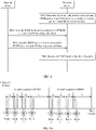
- the RMSI period may be a scheduling period of the RMSI. As shown in FIG.
- the RMSI may be repeatedly transmitted, or may not be repeatedly transmitted.
- Different repeated transmission may be performed in different scheduling manners, for example, repeated transmission performed by using different redundancy versions (RV) or in different scrambling manners, or repeated transmission performed by a base station based on a quantity of synchronization signal blocks (SS block), or repeated transmission performed by using different antenna ports, or repeated transmission performed by using different beams, or repeated transmission performed based on a purpose that the base station covers different areas.
- RV redundancy versions
- SS block synchronization signal blocks
- the scheduling period of the RMSI may also be referred to as a transmission time interval (TTI) period.
- TTI transmission time interval
- next generation communications system for example, a 5G new radio (NR) system, which is referred to as a 5G NR system for short.
- NR 5G new radio
- FIG. 3 is an architectural diagram of a communications system according to an embodiment of the present invention.
- the architecture of the communications system includes a core network, a network device, and a terminal device.
- the core network provides a related service for an entire communication process
- the network device indicates MIB information and RMSI for the accessed terminal device
- the terminal device performs cell access by using MSI information indicated by the network device.
- the terminal device is a device that has a wireless transceiving function.
- the terminal device may be deployed on land, including an indoor, outdoor, handheld, wearable, or vehicle-mounted device; or may be deployed on a water surface (for example, on a steamboat); or may be deployed in the air (for example, on a plane, a balloon, or a satellite).
- the terminal device may be a mobile phone (mobile phone), a tablet computer (Pad), a computer with a wireless transceiving function, a virtual reality (VR) terminal device, an augmented reality (AR) terminal device, a wireless terminal in industrial control (industrial control), a wireless terminal in self driving (self driving), a wireless terminal in remote medical (remote medical), or a wireless terminal in smart grid (smart grid), a wireless terminal in transportation safety (transportation safety), a wireless terminal in a smart city (smart city), a wireless terminal in a smart home (smart home), or the like.
- An application scenario is not limited in the embodiments of this application.
- the terminal device may also be sometimes referred to as user equipment (UE), an access terminal device, a UE unit, a UE station, a mobile station, a mobile console, a remote station, a remote terminal device, a mobile device, a UE terminal device, a terminal device, a wireless communications device, a UE proxy, a UE apparatus, or the like.
- UE user equipment
- the network device may be a network element on a network side in a 5G communications system, for example, may be a gNB in the 5G communications system.
- the network device supports determining, of a beam pair between the network device and the terminal device, which is performed by using a beam sweeping process, and monitors a plurality of beam pairs in a communication process, so as to improve robustness of a communication link.
- the network device further supports periodic broadcasting of the information.
- the network device may be a device, such as a network device, configured to communicate with a mobile device.
- the network device may be an access point (AP) in a WLAN, a relay node or an access point, a vehicle-mounted device, a wearable device, a network device (next generation NodeB, "gNB” or “gNodeB”) in a future 5G network, a network device in a future evolved PLMN, or the like.
- AP access point
- gNB next generation NodeB
- gNodeB next generation NodeB
- the network device serves a cell
- the terminal device communicates with the network device by using a transmission resource (for example, a frequency domain resource or a spectrum resource) used by the cell.
- the cell may be a cell corresponding to the network device (for example, a base station).
- the cell may belong to a macro base station, or may belong to a base station corresponding to a small cell (small cell).
- the small cell herein may include a metro cell (Metro cell), a micro cell (Micro cell), a pico cell (Pico cell), a femto cell (Femto cell), and the like. These small cells are characterized by a small coverage area and a low transmit power, and are applicable to providing a high-rate data transmission service.
- architecture of the communications system in FIG. 3 is only an example implementation in the embodiments of the present invention, and architectures of the communications system in the embodiments of the present invention include but are not limited to the foregoing architecture of the communications system.
- FIG. 4 is a schematic flowchart of an information sending and receiving method according to an embodiment of the present invention.
- the method may be applied to the communications system in FIG. 3 .
- the following performs description from a perspective of an interaction between a network device and a terminal device with reference to FIG. 4 .
- the method may include the following step S401 to step S403.
- Step S401 The terminal device determines, based on a physical broadcast channel PBCH period or an SS block burst set period, a first time point at which RMSI is to be received, where the RMSI is RMSI sent by the network device to the terminal device by using X as a period, and X is a multiple of the PBCH period, or X and the PBCH period or the SS block burst set period are in a one-to-one correspondence or a one-to-many relationship, and in a process in which the RMSI is sent once, the network device sends at least one piece of RMSI by using at least one beam or antenna port.
- Step S402 The network device sends the remaining minimum system information RMSI to the terminal device by using X as the period, where X is a multiple of the PBCH period or the SS block burst set period, or X and the PBCH period or the SS block burst set period are in a one-to-one correspondence or a one-to-many relationship, and in the process in which the RMSI is sent once, the network device sends the at least one piece of RMSI by using the at least one beam or antenna port.
- Step S403 The terminal device receives the RMSI based on the first time point.
- sending the RMSI in this application refers to sending the RMSI once.
- the network device sends the at least one piece of RMSI by using the at least one beam or antenna port.
- the network device schedules the RMSI once every X time by using L (greater than or equal to 1) beams or antenna ports, where the RMSI is carried by a physical downlink shared channel PDSCH, the PDSCH is scheduled by using a physical downlink control channel PDCCH, and the X time may be understood as an RMSI period.
- L greater than or equal to 1
- the RMSI is carried by a physical downlink shared channel PDSCH
- the PDSCH is scheduled by using a physical downlink control channel PDCCH
- the X time may be understood as an RMSI period.
- the network device repeatedly transmits the RMSI by using different RVs and/or repeatedly transmits the RMSI in different data scrambling manners every X time, where a quantity of repetition times is less than or equal to M, M is an integer greater than or equal to 1, and M ⁇ X is a scheduling period of the RMSI (which may also be referred to as a repetition rate).
- a beam/port used to send the RMSI is a beam/port of an SS block, and a quantity of beams/ports used to send the RMSI may be less than or equal to a quantity of beams/ports of the SS block).
- the antenna port used to transmit the RMSI and the SS block are in a quasi co-located QCL relationship.
- N beams used by the network device may be the same as or quasi co-located (QCL) with transmit beams of SS blocks included in a synchronization signal block set SS block burst set, where QCL parameters include at least one of the following items: an average gain, an average delay, a delay spread, a Doppler shift, a Doppler spread, and a Spatial Tx/Rx parameter.
- QCL parameters include at least one of the following items: an average gain, an average delay, a delay spread, a Doppler shift, a Doppler spread, and a Spatial Tx/Rx parameter.
- the spatial Tx/Rx parameter includes an angle of arrival (AoA)/angle of departure (AoD), a dominant AoA/AoD, an average AoA/AoD, a power angular spectrum (PAS) of AoA/AoD, transmit/receive channel correlation, transmit/receive beamforming, spatial channel correlation, and the like.
- AoA angle of arrival
- AoD angle of departure
- AoD average AoA/AoD
- PAS power angular spectrum
- the RMSI may include one or more of configuration information of a random access channel, configuration information of a paging channel, configuration information of a downlink shared channel, configuration information of an uplink shared channel, a public land mobile network identity list PLMN-Identity List, a tracking area code, cell barring access information, scheduling information of other system information OSI, scheduling information of a system information block SIB 1, a system information value tag (SI Value Tag), bandwidth indication information, and cell reselection information.
- SIB system information value tag
- bandwidth indication information bandwidth indication information
- cell reselection information may include one or more of configuration information of a random access channel, configuration information of a paging channel, configuration information of a downlink shared channel, configuration information of an uplink shared channel, a public land mobile network identity list PLMN-Identity List, a tracking area code, cell barring access information, scheduling information of other system information OSI, scheduling information of a system information block SIB 1, a system information value tag (SI Value Tag), bandwidth indication information,
- the network device or the terminal device may pre-store information about an association relationship (for example, an integral multiple or a fractional multiple relationship) between the PBCH period or the SS block burst set period and the RMSI period (namely, the X time).
- the terminal device may first learn of the PBCH period or the SS block burst set period by using the MIB information, and then finally determine the RMSI period based on the information about the relationship between the RMSI period and the PBCH period.
- the information about the association relationship between the PBCH period or the SS block burst set period and the RMSI period may further be sent by the network device to the terminal device.
- the network device may further send indication information to the terminal device, where the indication information is used to indicate the PBCH period or the SS block burst set period.
- the network device may indicate the PBCH period or the SS block burst set period to the terminal device in the MIB information on a PBCH in an explicit or implicit manner.
- the indication information may be the MIB information.
- the terminal device may learn of the PBCH period, and then determine, based on the pre-specified association relationship (for example, a multiple relationship) between the PBCH period and the RMSI period, the first time point at which the RMSI is to be received.
- the network device may also add the indication information to information on the PBCH or another channel. This is not specifically limited in this application. It may be further understood that, because the RMSI on the PDSCH is a periodically broadcast system message, the first time point may be one time point, or may be a plurality of periodic time points. For example, the first time point is a 5 th ms, a 10 th ms, a 15 th ms, or the like.
- the network device side may send the RMSI to the terminal device on the physical downlink shared channel PDSCH every X time based on the preconfigured or pre-stored information about the association relationship between the PBCH period and the RMSI period. For example, the network device sends the RMSI to the terminal device every X time through PDSCH, where X is equal to 5 ms, 10 ms, 20 ms, 40 ms, 80 ms, or 160 ms.
- the terminal device monitors the RMSI on the PDSCH at the first time point (which may be one time point or a plurality of time points).
- the RMSI period is related to the PBCH period. Therefore, the RMSI period and the PBCH period may be both learned provided that any one of the periods is notified or indicated, thereby saving overheads and simplifying an indication process.
- the following describes how to specify the association relationship between the PBCH period and the RMSI period in this application.
- X is a multiple of the PBCH period or the SS block burst set period, and there may specifically be an integer multiple relationship or a fractional multiple relationship between X and the PBCH period or the SS block burst set period.
- Manner 1 and Manner 2 performs description by using Manner 1 and Manner 2 as examples.
- the network device indicates the PBCH period or the SS block burst set period by using the MIB information on the PBCH.
- the PBCH period or the SS block burst set period may be 5 ms, 10 ms, 20 ms, 40 ms, 80 ms, or 160 ms. 3.
- the terminal device learns of the PBCH period or the SS block burst set period, and may determine, based on information that is about the relationship between the PBCH period and the RMSI period and that is pre-stored based on a protocol or received from the network device, the period in which the RMSI is to be received, to be specific, the first time point at which the RMSI is to be received. Details are shown in the following Table 1.
- Table 1 PBCH period (or SS block burst set period) RMSI period (X time) Association relationship 5 ms 10 ms 2 times 10 ms 20 ms 2 times 20 ms 40 ms 2 times 40 ms 80 ms 2 times 80 ms 160 ms 2 times 160 ms 320 ms 2 times ⁇ ⁇ ⁇
- a specific implementation may be as follows: 1.
- the RMSI period is N times the PBCH period or the SS block burst set period. There may be a plurality of values of N. In other words, a corresponding value of N may vary with the PBCH period.
- the RMSI period is always four times the PBCH period.
- the RMSI period is always twice the PBCH period or the SS block burst set period.
- the network device indicates the PBCH period or the SS block burst set period by using the MIB information on the PBCH.
- the PBCH period may be 5 ms, 10 ms, 20 ms, 40 ms, 80 ms, or 160 ms. 3.
- the terminal device After receiving the MIB information added by the network device to the PBCH, the terminal device learns of the PBCH period or the SS block burst set period, and may determine, based on information that is about the relationship between the PBCH period and the RMSI period and that is pre-stored based on a protocol or received from the network device, the period in which the RMSI is to be received, to be specific, the first time point at which the RMSI is to be received. Details are shown in the following Table 2.
- Table 2 PBCH period (or SS block burst set period) RMSI period (X time) Association relationship 5 ms 20 ms 4 times 10 ms 40 ms 4 times 20 ms 80 ms 4 times 40 ms 80 ms 2 times 80 ms 160 ms 2 times 160 ms 320 ms 2 times ⁇ ⁇ ⁇
- values of the PBCH period and the RMSI period may also be directly specified, for example, the values are shown in the following Table 3.
- RMSI period (X time) Association relationship 5 ms 40 ms None 10 ms 40 ms None 20 ms 40 ms None 40 ms 40 ms None 80 ms 40 ms None 160 ms 40 ms None ⁇ ⁇ ⁇
- X and the PBCH period or the SS block burst set period are in a one-to-one correspondence or a one-to-many relationship.
- the following performs description by using Manner 3 and Manner 4 as examples.
- Manner 3 In Manner 3, a table of a mapping relationship between the RMSI period and the PBCH period or the SS block burst set period is preconfigured.
- the RMSI period and the PBCH period may be in a one-to-one correspondence, and a specific implementation may be as follows: 1.
- a direct mapping relationship between the RMSI period and the PBCH period or the SS block burst set period may be a one-to-one mapping relationship. For example, in the one-to-one relationship, when the PBCH period is 5 ms, the RMSI period is 10 ms, or when the PBCH period is 10 ms, the RMSI period is 20 ms. 2.
- the network device indicates the PBCH period or the SS block burst set period by using the MIB information on the PBCH.
- the PBCH period may be 5 ms, 10 ms, 20 ms, 40 ms, 80 ms, or 160 ms. 3.
- the terminal device learns of the PBCH period or the SS block burst set period, and may determine, based on information that is about the relationship between the PBCH period and the RMSI period and that is pre-stored based on a protocol or received from the network device, the period in which the RMSI is to be received, to be specific, the first time point at which the RMSI is to be received.
- the terminal device determines the PBCH period based on the RMSI period. Details are shown in the following Table 4. Table 4 PBCH period (or SS block burst set period) RMSI period (X time) Association relationship 5 ms 10 ms One-to-one correspondence 10 ms 20 ms One-to-one correspondence 20 ms 30 ms One-to-one correspondence 40 ms 40 ms One-to-one correspondence 80 ms 60 ms One-to-one correspondence 160 ms 80 ms One-to-one correspondence
- Manner 4 In Manner 4, a table of a mapping relationship between the RMSI period and the PBCH period or the SS block burst set period is preconfigured.
- the PBCH period and the RMSI period may be in a one-to-many relationship, and a specific implementation may be as follows:
- FIG. 5 is a schematic flowchart of another information sending and receiving method according to an embodiment of the present invention.
- the method may be applied to the communications system in FIG. 3 .
- the following performs description from a perspective of an interaction between a network device and a terminal device with reference to FIG. 5 .
- the method may include the following step S501 to step S503.
- Step S501 The terminal device determines, based on a physical broadcast channel PBCH period or an SS block burst set period, a first time point at which RMSI is to be received.
- Step S502 The network device sends the remaining minimum system information RMSI to the terminal device by using X as a period in one transmission time interval TTI period.
- Step S503 The terminal device receives the RMSI based on the first time point.
- step S501 and step S503 refer to related descriptions of step S401 and step S403 corresponding to FIG. 4 . Details are not described herein again.
- step S502 and step S402 corresponding to FIG. 4 lie in that, in step S402 corresponding to FIG. 4 , there is no concept of a TTI, in other words, there is no repeated transmission of the RMSI.
- the TTI period of the RMSI is a scheduling period of the RMSI.
- the RMSI may be repeatedly transmitted, or may not be repeatedly transmitted. Different repeated transmission may be performed in different scheduling manners, for example, repeated transmission performed by using different RVs or in different scrambling manners, or repeated transmission performed by a base station based on a quantity of SS blocks.
- the scheduling period of the RMSI may also be referred to as the TTI period of the RMSI.
- the network device repeatedly transmits the RMSI every X time, where the RMSI is repeatedly transmitted a plurality of times. Therefore, the terminal device needs to know a specific period of repeated transmission and a quantity of times of repeated transmission of the RMSI, so as to receive the RMSI at a correct first time point.
- FIG. 6 is a schematic diagram of repeatedly transmitting RMSI in a TTI according to an embodiment of the present invention.
- a TTI period is 80 ms
- RMSI is repeatedly transmitted four times in one TTI period
- the RMSI is repeatedly transmitted on a PDSCH every 20 ms.
- new RMSI is repeatedly transmitted. The following performs description by using two types of association modes.
- the TTI period is a preset value
- X is associated with the PBCH period.
- the network device and the terminal device agree on that the TTI is a fixed period, and then agree on an association relationship between a period X and the PBCH period or the SS block burst set period, where the period X is a period in which the repeated RMSI is to be transmitted in one TTI.
- the terminal device may determine the first time point at which the RMSI is to be received each time, provided that the terminal device learns of the PBCH period. The following describes how to specify an association relationship between X and the PBCH period in this application.
- X is a multiple of the PBCH period or the SS block burst set period, and there may specifically be an integer multiple relationship or a fractional multiple relationship between X and the PBCH period or the SS block burst set period.
- Manner 5 performs description by using Manner 5 as an example.
- the TTI period of the RMSI namely, the scheduling period of the RMSI
- the TTI period of the RMSI is a preset value, to be specific, a preset fixed value, for example, 160 ms or 80 ms
- the association relationship between the transmission period X and the PBCH period or the SS block burst set period is a multiple relationship, where the transmission period X is a period in which the repeated RMSI is to be transmitted in the TTI period.
- a specific implementation may be as follows: 1.
- the TTI period of the RMSI is fixed.
- X is N times the PBCH period or the SS block burst set period.
- the TTI is fixed at 160 ms
- a value of N is fixed at 1.
- the network device indicates the PBCH period, the SS block burst set period, or the RMSI period by using MIB information on a PBCH.
- the PBCH period may be 5 ms, 10 ms, 20 ms, 40 ms, 80 ms, or 160 ms. 3.
- the terminal device learns of the PBCH period, and may determine, based on information that is about the relationship between the PBCH period and X and that is pre-stored based on a protocol or received from the network device, the first time point at which the RMSI is to be received. Alternatively, the terminal device may also directly obtain the RMSI period, and obtain the PBCH period based on the RMSI period. Details are shown in the following Table 6.
- Table 6 PBCH period (or SS block burst set period) TTI period A quantity of times of repeated transmission Period X of repeated transmission Association relationship 5 ms 160 ms 32 5 ms X is one time the PBCH period 10 ms 16 10 ms X is one time the PBCH period 20 ms 8 20 ms X is one time the PBCH period 40 ms 4 40 ms X is one time the PBCH period 80 ms 2 80 ms X is one time the PBCH period 160 ms 1 160 ms X is one time the PBCH period ⁇ ⁇ ⁇ ⁇
- X and the PBCH period are in a one-to-one correspondence.
- the following performs description by using Manner 6 as an example.
- the TTI period is a preset value, to be specific, a preset fixed value, for example, 160 ms or 80 ms
- the association relationship between the transmission period X and the PBCH period or the SS block burst set period is a one-to-one correspondence, where the transmission period X is a period in which the repeated RMSI is to be transmitted in the TTI period.
- a specific implementation may be as follows: 1.
- the TTI period is fixed.
- a direct mapping relationship between the period of repeated transmission and the PBCH period or the SS block burst set period may be a one-to-one mapping relationship, where the period of repeated transmission is a period in which the repeated RMSI is to be transmitted in one TTI.
- the network device indicates the PBCH period, the SS block burst set period, or the RMSI period by using MIB information on a PBCH.
- the PBCH period may be 5 ms, 10 ms, 20 ms, 40 ms, 80 ms, or 160 ms. 3.
- the terminal device After receiving the MIB information added by the network device to the PBCH, the terminal device learns of the PBCH period, and may determine, based on information that is about the relationship between the PBCH period or the SS block burst set period and the RMSI period and that is pre-stored based on a protocol or received from the network device, the period in which the RMSI is to be received, to be specific, the first time point at which the RMSI is to be received, and information about the PBCH period. Details are shown in the following Table 7.
- Table 7 PBCH period (or SS block burst set period) TTI period A quantity of times of repeated transmission Period X of repeated transmission Association relationship 5 ms 160 ms 16 10 ms One-to-one correspondence 10 ms 8 20 ms One-to-one correspondence 20 ms 5 32 ms One-to-one correspondence 40 ms 4 40 ms One-to-one correspondence 80 ms 2 80 ms One-to-one correspondence 160 ms 1 160 ms One-to-one correspondence ⁇ ⁇ ⁇ ⁇
- X and the PBCH period or the SS block burst set period are in a one-to-many relationship.
- the following performs description by using Manner 7 as an example.
- the TTI period is a preset value, to be specific, a preset fixed value, for example, 160 ms or 80 ms
- the association relationship between the transmission period X and the PBCH period or the SS block burst set period is a one-to-many correspondence, where the transmission period X is a period in which the repeated RMSI is to be transmitted in the TTI period.
- a specific implementation may be as follows: 1.
- the TTI period is fixed.
- a direct mapping relationship between the period of repeated transmission and the PBCH period or the SS block burst set period may be a one-to-many mapping relationship, where the period of repeated transmission is a period in which the repeated RMSI is to be transmitted in one TTI.
- the network device indicates the PBCH period or the SS block burst set period by using MIB information on a PBCH.
- the PBCH period may be 5 ms, 10 ms, 20 ms, 40 ms, 80 ms, or 160 ms. 3.
- the terminal device After receiving the MIB information added by the network device to the PBCH, the terminal device learns of the PBCH period or the SS block burst set period or the RMSI period, and may determine, based on information that is about the relationship between the PBCH period and the RMSI period and that is pre-stored based on a protocol or received from the network device, the period in which the RMSI is to be received, to be specific, the first time point at which the RMSI is to be received, or the PBCH period. Details are shown in the following Table 8.
- Table 8 PBCH period (or SS block burst set period) TTI period A quantity of times of repeated transmission Period X of repeated transmission Association relationship 5 ms 80 ms 2 40 ms One-to-many correspondence 10 ms 20 ms 4 20 ms One-to-many correspondence 40 ms 80 ms 8 10 ms One-to-many correspondence 160 ms ⁇ ⁇ ⁇ ⁇
- X is a preset value
- the TTI period is associated with the PBCH period.
- the network device and the terminal device agree on that a period, of repeated transmission, in which the repeated RMSI is to be transmitted in one TTI is fixed, and then agree on an association relationship between one TTI period and the PBCH period.
- the terminal device may simultaneously determine the RMSI period or information about the PBCH period and the first time point at which the RMSI is to be received each time, provided that the terminal learns of any one of the PBCH period and the RMSI period. The following describes how to specify an association relationship between the TTI period and the PBCH period in this application.
- the TTI period is a multiple of the PBCH period, and there may specifically be an integer multiple relationship or a fractional multiple relationship between the TTI period and the PBCH period.
- the following performs description by using Manner 8 as an example.
- Manner 8 In Manner 8, the period X, of repeated transmission, in which the repeated RMSI is to be transmitted in one TTI is a preset value, to be specific, a preset fixed value, and the association relationship between the TTI period and the PBCH period or the SS block burst set period is a multiple relationship.
- a specific implementation may be as follows: 1. X is fixed, and the TTI period is N times the PBCH period or the SS block burst set period. For example, X is fixed at 10 ms, and a value of N is fixed at 4.
- the network device indicates the PBCH period, the SS block burst set period, or the RMSI period by using MIB information on the PBCH. 3.
- the terminal device After receiving the MIB information added by the network device to the PBCH, the terminal device learns of the PBCH period or the SS block burst set period, and may simultaneously determine, based on information that is about the relationship between the PBCH period and X and that is pre-stored based on a protocol or received from the network device, the period in which the RMSI is to be received, to be specific, the first time point at which the RMSI is to be received, and information about the PBCH period. Details are not shown in the following Table 9.
- Table 9 PBCH period (or SS block burst set period) TTI period A quantity of times of repeated transmission Transmission period X Association relationship 5 ms 20 ms 2 10 ms TTI period is four times the PBCH period 10 ms 40 ms 4 10 ms TTI period is four times the PBCH period 20 ms 80 ms 8 10 ms TTI period is four times the PBCH period 40 ms 160 ms 16 10 ms TTI period is four times the PBCH period 80 ms 320 ms 32 10 ms TTI period is four times the PBCH period 160 ms 640 ms 64 10 ms TTI period is four times the PBCH period ⁇ ⁇ ⁇ ⁇
- the TTI period and the PBCH period are in a one-to-one correspondence.
- the following performs description by using Manner 9 as an example.
- Manner 9 In Manner 9, the period X, of repeated transmission, in which the repeated RMSI is to be transmitted in one TTI is a preset value, to be specific, a preset fixed value, and the association relationship between the TTI period and the PBCH period or the SS block burst set period is a one-to-one correspondence.
- a specific implementation may be as follows: 1. X is fixed, and a direct mapping relationship between the TTI period and the PBCH period or the SS block burst set period may be a one-to-one mapping relationship.
- the network device indicates the PBCH period, the SS block burst set period, or the TTI period by using MIB information on a PBCH.
- the PBCH period may be 5 ms, 10 ms, 20 ms, 40 ms, 80 ms, or 160 ms. 3.
- the terminal device After receiving the MIB information added by the network device to the PBCH, the terminal device learns of the PBCH period or the SS block burst set period or information about the TTI period of the RMSI, and may determine, based on information that is about a relationship between the PBCH period and the RMSI period and that is pre-stored based on a protocol or received from the network device, the information about the TTI period in which the RMSI is to be received. Details are shown in the following Table 10.
- Table 10 PBCH period (or SS block burst set period) TTI period A quantity of times of repeated transmission Transmission period X Association relationship 5 ms 20 ms 2 10 ms One-to-one correspondence 10 ms 30 ms 3 One-to-one correspondence 20 ms 40 ms 4 One-to-one correspondence 40 ms 50 ms 5 One-to-one correspondence 80 ms 60 ms 6 One-to-one correspondence 160 ms 70 ms 7 One-to-one correspondence ⁇ ⁇ ⁇
- the TTI period and the PBCH period are in a one-to-many relationship.
- the following performs description by using Manner 10 as an example.
- Manner 10 In Manner 10, X is a preset value, to be specific, a preset fixed value, and the association relationship between the TTI period and the PBCH period or the SS block burst set period is a one-to-many correspondence, where the transmission period X is a period in which the repeated RMSI is to be transmitted in the TTI period.
- a specific implementation may be as follows: 1. A value of X is fixed, and it is specified that a correspondence between the TTI period and the PBCH period or the SS block burst set period may be a one-to-many correspondence.
- the network device indicates the PBCH period, the SS block burst set period, or information about the RMSI period by using MIB information on the PBCH.
- the PBCH period may be 5 ms, 10 ms, 20 ms, 40 ms, 80 ms, or 160 ms. 3.
- the terminal device After receiving the MIB information added by the network device to the PBCH, the terminal device learns of information about the PBCH period or information about the RMSI period, and may simultaneously determine, based on information that is about a relationship between the PBCH period or the SS block burst set period and the RMSI period and that is pre-stored based on a protocol or received from the network device, some or all information about the period in which the RMSI is to be received, or some or all of information about the PBCH period.
- Table 11 The relationship is shown in the following Table 11.
- Table 11 PBCH period (or SS block burst set period) TTI period A quantity of times of repeated transmission Period X of repeated transmission Association relationship 5 ms 20 ms 2 10 ms One-to-many correspondence 10 ms 20 ms 40 ms 4 One-to-many 40 ms correspondence 80 ms 80 ms 8 One-to-many correspondence 160 ms ⁇ ⁇ ⁇
- FIG. 7 is a schematic flowchart of still another information sending and receiving method according to an embodiment of the present invention.
- the method may be applied to the communications system in FIG. 3 .
- the following performs description from a perspective of an interaction between a network device and a terminal device with reference to FIG. 7 .
- the method may include the following step S701 to step S703.
- Step S701 The terminal device determines, based on a physical broadcast channel PBCH period or an SS block burst set period, a first time point at which RMSI is to be received.
- Step S702 The network device sends the RMSI to the terminal device X times in one TTI period.
- Step S703 The terminal device receives the RMSI based on the first time point.
- step S701 and step S703 refer to related descriptions of step S401 and step S403 corresponding to FIG. 4 . Details are not described herein again.
- the TTI period is a preset value
- X is a multiple of the PBCH period or the SS block burst set period
- X and the PBCH period are in a one-to-one correspondence or a one-to-many relationship, and in a process in which the RMSI is sent once, the network device sends at least one piece of RMSI by using at least one beam or antenna port.
- step S702 and step S402 corresponding to FIG. 4 lie in that, in step S402 corresponding to FIG. 4 , there is no concept of a TTI, in other words, there is no repeated transmission of the RMSI.
- that the network device sends the RMSI to the terminal device X times means that the RMSI is repeatedly transmitted X times in one TTI. Repeated transmission performed X times may be periodic repeated transmission, or may be non-periodic repeated transmission. Therefore, the terminal device needs to know the TTI period of the RMSI and a specific transmission interval for repeatedly transmitting the RMSI in the TTI period, so as to receive the RMSI at a correct first time.
- FIG. 6 is a schematic diagram of repeatedly transmitting RMSI in a TTI according to an embodiment of the present invention.
- a TTI period is 80 ms
- RMSI is repeatedly transmitted four times in one TTI period
- a transmission time interval may be a periodic transmission interval of 20 ms, or may be non-periodic transmission intervals of 10 ms, 20 ms, and 30 ms. The following performs description by using two types of association modes.
- the TTI period is a preset value
- a value of X is associated with the PBCH period or the SS block burst set period, where X is a quantity of times of repeated transmission in one TTI.
- the network device and the terminal device agree on that the TTI is a fixed period, and then agree on an association relationship between X and the PBCH period or the SS block burst set period, where X is the quantity of times of repeatedly transmitting the RMSI in one TTI.
- the terminal device may determine the first time at which the RMSI is to be received each time, provided that the terminal device learns of the PBCH period or the SS block burst set period. The following describes how to specify an association relationship between X and the PBCH period in this application.
- the TTI period is a multiple of the PBCH period or the SS block burst set period, and there may specifically be an integer multiple relationship or a fractional multiple relationship between the TTI period and the PBCH period or the SS block burst set period.
- Manner 11 performs description by using Manner 11 as an example.
- Manner 11 In Manner 11, the TTI period is a preset value, to be specific, a preset fixed value, and the association relationship between X and the PBCH period or the SS block burst set period is a multiple relationship, where X is the quantity of times of repeatedly transmitting the RMSI in the TTI period.
- a specific implementation may be as follows: 1.
- the TTI period of the RMSI is fixed, and it is specified that X is N times the PBCH period or the SS block burst set period. For example, the TTI is fixed at 160 ms, and a value of N is fixed at 2/5.
- the network device indicates the PBCH period or the SS block burst set period by using MIB information on a PBCH.
- the PBCH period may be 5 ms, 10 ms, 20 ms, 40 ms, 80 ms, or 160 ms. 3.
- the terminal device After receiving the MIB information added by the network device to the PBCH, the terminal device learns of the PBCH period or the SS block burst set period or information about an RMSI period, and may simultaneously determine, based on information that is about the relationship between the PBCH period and X and that is pre-stored based on a protocol or received from the network device, the period in which the RMSI is to be received and the PBCH period. Details are shown in the following Table 12.
- Table 12 PBCH period (or SS block burst set period) TTI period
- a quantity X of times of repeated transmission Transmission period Association relationship 5 ms 160 ms 2 160 ms X is 2/5 times the PBCH period 10 ms 4
- 80 ms X is 2/5 times the PBCH period 20 ms 8
- 40 ms X is 2/5 times the PBCH period 40 ms 16
- 20 ms X is 2/5 times the PBCH period 80 ms 32
- 10 ms X is 2/5 times the PBCH period 160 ms 64 5 ms X is 2/5 times the PBCH period ⁇ ⁇ ⁇ ⁇
- X and the PBCH period or the SS block burst set period are in a one-to-one correspondence.
- Manner 12 performs description by using Manner 12 as an example.
- the TTI period is a preset value, to be specific, a preset fixed value, and the association relationship between X and the PBCH period or the SS block burst set period is a one-to-one correspondence, where X is the quantity of times of repeatedly transmitting the RMSI in the TTI period.
- a specific implementation may be as follows:
- a direct mapping relationship between X and the PBCH period or the SS block burst set period may be a one-to-one mapping relationship.
- the TTI is fixed at 160 ms.
- the network device indicates the PBCH period, the SS block burst set period, or information about the RMSI period by using MIB information on a PBCH.
- the PBCH period may be 5 ms, 10 ms, 20 ms, 40 ms, 80 ms, or 160 ms. 3.
- the terminal device learns of the PBCH period or the SS block burst set period or the RMSI period, and may determine, based on information that is about a relationship between the PBCH period and the RMSI period and that is pre-stored based on a protocol or received from the network device, the period in which the RMSI is to be received, to be specific, the first time point, or the PBCH period. Details are shown in the following Table 13.
- Table 13 PBCH period (or SS block burst set period) TTI period A quantity X of times of repeated transmission Transmission period Association relationship 5 ms 160 ms 64 5 ms One-to-one correspondence 10 ms 32 10 ms One-to-one correspondence 20 ms 16 20 ms One-to-one correspondence 40 ms 8 40 ms One-to-one correspondence 80 ms 5 64 ms One-to-one correspondence 160 ms 4 80 ms One-to-one correspondence ⁇ ⁇ ⁇ ⁇
- X and the PBCH period are in a one-to-many relationship, where X is the quantity of times of repeatedly transmitting the RMSI in one TTI.
- the following performs description by using Manner 13 as an example.
- the TTI period is a preset value, to be specific, a preset fixed value
- the association relationship between X and the PBCH period or the SS block burst set period is a one-to-many correspondence, where X is the quantity of times of repeatedly transmitting the RMSI in the TTI period.
- a specific implementation may be as follows: 1.
- the TTI period is fixed, and it is specified that a direct mapping relationship between X and the PBCH period or the SS block burst set period may be a one-to-many mapping relationship, where X is the quantity of times of repeatedly transmitting the RMSI in one TTI.
- the TTI period is fixed at 160 ms.
- the quantity X of times of repeated transmission is equal to 4, and a period of repeated transmission is 80 ms; or when the PBCH period is 20 ms and 40 ms, the quantity X of times of repeated transmission is equal to 8, and a period of repeated transmission is 40 ms.
- the network device indicates the PBCH period, the SS block burst set period, or information about the RMSI period by using MIB information on a PBCH.
- the PBCH period may be 5 ms, 10 ms, 20 ms, 40 ms, 80 ms, or 160 ms. 3.
- the terminal device After receiving the MIB information added by the network device to the PBCH, the terminal device learns of the PBCH period or the SS block burst set period, and may determine, based on information that is about a relationship between the PBCH period and the quantity of times of repeated transmission and that is pre-stored based on a protocol or received from the network device, all or some of the information about the period in which the RMSI is to be received, or all or some of information about the PBCH period. Details are shown in the following Table 14.
- Table 14 PBCH period (or SS block burst set period) TTI period A quantity X of times of repeated transmission Transmission period Association relationship 5 ms 160 ms 4 80 ms One-to-many correspondence 10 ms 20 ms 8 40 ms One-to-many correspondence 40 ms 80 ms 16 20 ms One-to-many correspondence 160 ms ⁇ ⁇ ⁇ ⁇
- a quantity X of times of repeatedly transmitting the RMSI in one TTI is a preset value.
- the network device indicates a value of X by using signaling.
- the signaling may specifically be RRC signaling, DCI signaling, or a MAC CE.
- the TTI period is associated with the PBCH period.
- the network device and the terminal device agree on that the quantity X of times of repeatedly transmitting the RMSI in one TTI is fixed. Then, the network device and the terminal device agree on an association relationship between one TTI period and the PBCH period.
- the terminal device may determine a period in which the RMSI is to be received each time, to be specific, the first time, provided that the terminal device learns of the PBCH period.
- the following describes how to specify an association relationship between the TTI period and the PBCH period in this application.
- the TTI period is a multiple of the PBCH period, and there may specifically be an integer multiple relationship or a fractional multiple relationship between the TTI period and the PBCH period.
- the following performs description by using Manner 14 as an example.
- Manner 14 In Manner 14, the quantity X of times of repeatedly transmitting the RMSI in one TTI is a preset value, to be specific, a preset fixed value, and the association relationship between the TTI period and the PBCH period or the SS block burst set period is a multiple relationship.
- a specific implementation may be as follows: 1.
- the quantity of times of repeatedly transmitting the RMSI in the TTI period is fixed.
- the quantity of times of repeated transmission is always X regardless of the PBCH period.
- the quantity X of times of repeated transmission in one TTI period is equal to 4.
- the TTI period is associated with the PBCH period.
- the TTI period When the PBCH period is 20 ms, the TTI period is 80 ms, and the quantity X of times of repeated transmission is fixed at 4, and in this case, the period of repeated transmission is 20 ms.
- the TTI period When the PBCH period is 40 ms, the TTI period is 160 ms, the quantity X of times of repeated transmission is fixed at 4, and the period of repeated transmission is 40 ms. 3.
- the network device indicates the PBCH period, the SS block burst set period, or information about the RMSI period by using MIB information on a PBCH.
- the PBCH period may be 5 ms, 10 ms, 20 ms, 40 ms, 80 ms, or 160 ms. 4.
- the terminal device After receiving the MIB information added by the network device to the PBCH, the terminal device learns of the PBCH period or the SS block burst set period, and may simultaneously determine, based on information that is about a relationship between the PBCH period and the RMSI period and that is pre-stored based on a protocol or received from the network device, all or some of the information about the period in which the RMSI is to be received and some or all of information about the PBCH period. Details are shown in the following Table 15.
- TTI period A quantity X of times of repeated transmission Transmission period Association relationship 5 ms 20 ms 4 5 ms
- the TTI period is four times the PBCH period 10 ms 40 ms 10 ms
- the TTI period is four times the PBCH period 20 ms 80 ms 20 ms
- the TTI period is four times the PBCH period 40 ms 160 ms 40 ms
- the TTI period is four times the PBCH period 80 ms 320 ms 80 ms
- the TTI period is four times the PBCH period 160 ms 640 ms 160 ms
- the TTI period is four times the PBCH period ⁇ ⁇ ⁇ ⁇
- the TTI period and the PBCH period are in a one-to-one correspondence.
- the following performs description by using Manner 15 as an example.
- Manner 15 In Manner 15, the quantity X of times of repeatedly transmitting the RMSI in one TTI is a preset value, to be specific, a preset fixed value, and the association relationship between the TTI period and the PBCH period or the SS block burst set period is a one-to-one correspondence.
- a specific implementation may be as follows: 1. A value of X is fixed, and a direct mapping relationship between the TTI period and the PBCH period or the SS block burst set period may be a one-to-one mapping relationship.
- the network device indicates the PBCH period, the SS block burst set period, or information about the RMSI period by using MIB information on a PBCH.
- the PBCH period may be 5 ms, 10 ms, 20 ms, 40 ms, 80 ms, or 160 ms. 3.
- the terminal device After receiving the MIB information added by the network device to the PBCH, the terminal device learns of the PBCH period, and may simultaneously determine, based on information that is about a relationship between the PBCH period or the SS block burst set period and the RMSI period and that is pre-stored based on a protocol or received from the network device, all or some of the information about the period in which the RMSI is to be received and some or all of information about the PBCH period. Details are shown in the following Table 16.
- Table 16 PBCH period (or SS block burst set period) TTI period A quantity X of times of repeated transmission Transmission period Association relationship 5 ms 20 ms 4 5 ms One-to-one correspondence 10 ms 40 ms 10 ms One-to-one correspondence 20 ms 80 ms 20 ms One-to-one correspondence 40 ms 120 ms 30 ms One-to-one correspondence 80 ms 160 ms 40 ms One-to-one correspondence 160 ms 240 ms 60 ms One-to-one correspondence ⁇ ⁇
- the TTI period and the PBCH period are in a one-to-many relationship.
- the following performs description by using Manner 16 as an example.
- Manner 16 In Manner 16, X is a preset value, to be specific, a preset fixed value, and the association relationship between the TTI period and the PBCH period or the SS block burst set period is a one-to-many correspondence, where X is the quantity of times of repeatedly transmitting the RMSI in the TTI period.
- a specific implementation may be as follows: 1. A value of X is fixed, and a correspondence between the TTI period and the PBCH period or the SS block burst set period may be a one-to-many correspondence.
- the network device indicates the PBCH period or the SS block burst set period or information about the RMSI period by using MIB information on a PBCH.
- the PBCH period or the SS block burst set period may be 5 ms, 10 ms, 20 ms, 40 ms, 80 ms, or 160 ms. 3.
- the terminal device After receiving the MIB information added by the network device to the PBCH, the terminal device learns of the PBCH period or the SS block burst set period, and may simultaneously determine, based on information that is about a relationship between the PBCH period and the RMSI period and that is pre-stored based on a protocol or received from the network device, all or some of the information about the period in which the RMSI is to be received and some or all information about the PBCH period. Details are shown in the following Table 17.
- Table 17 PBCH period (or SS block burst set period) TTI period A quantity X of times of repeated transmission Transmission period Association relationship 5 ms 20 ms 4 5 ms One-to-many correspondence 10 ms 20 ms 40 ms 10 ms One-to-many correspondence 40 ms 80 ms 80 ms 20 ms One-to-many correspondence 160 ms ⁇ ⁇
- This application further provides Manner 17:
- the terminal device may learn of the quantity of times of repeated transmission by using the PBCH period. Further, because the transmission interval in one TTI is fixed, the terminal device may finally determine a complete TTI period based on the PBCH period. Details are shown in the following Table 18.
- Table 18 PBCH period (or SS block burst set period) TTI period A quantity X of times of repeated transmission Transmission interval Association relationship 5 ms 30 ms 2 10 ms One-to-many correspondence 10 ms 30 ms 2 10 ms One-to-many correspondence 20 ms 80 ms 3 10 ms and 20 ms One-to-many correspondence 40 ms 80 ms 3 10 ms and 20 ms One-to-many correspondence 80 ms 160 ms 4 10 ms, 20 ms, and 50 ms One-to-many correspondence 160 ms 160 ms 4 10 ms, 20 ms, and 40 ms One-to-many correspondence ⁇ ⁇ ⁇ ⁇
- the terminal device may learn of the quantity of times of repeated transmission by using the PBCH period or the SS block burst set period. Further, because the transmission interval in one TTI is fixed, the terminal device may finally determine a complete TTI period based on the PBCH period. Details are shown in the following Table 19.
- TTI period A quantity X of times of repeated transmission Transmission interval 5 ms 80 ms 4 10 ms, 20 ms, 50 ms, and 80 ms 10 ms 80 ms 4 10 ms, 20 ms, 50 ms, and 80 ms 20 ms 80 ms 4 10 ms, 20 ms, 50 ms, and 80 ms 40 ms 160 ms 5 10 ms, 20 ms, 50 ms, and 80 ms 80 ms 160 ms 5 10 ms, 20 ms, 50 ms, and 80 ms 160 ms 160 ms 5 10 ms, 20 ms, 50 ms, and 80 ms 160 ms 160 ms 5 10 ms, 20 ms, 40 ms, and 80 ms ⁇ ⁇ ⁇ ⁇ ⁇
- This application further provides Manner 19: When a plurality of times of repeated transmissions in one TTI are non-periodic, assuming that the transmission interval is agreed on in advance, and it is specified that the TTI period and the quantity of times of repeated transmission are also fixed, in this case, the terminal device may directly learn of the first time. Details are shown in the following Table 20.
- Table 20 PBCH period (or SS block burst set period) TTI period A quantity X of times of repeated transmission Transmission interval 5 ms 80 ms 4 10 ms, 20 ms, and 40 ms 10 ms 10 ms, 20 ms, and 40 ms 20 ms 10 ms, 20 ms, and 40 ms 40 ms 10 ms, 20 ms, and 40 ms 80 ms 10 ms, 20 ms, and 40 ms 160 ms 10 ms, 20 ms, and 40 ms ⁇ ⁇
- This application further provides Manner 20:
- the scheduling period of the RMSI is 80 ms or 160 ms
- the quantity of repetitions based on different RVs or other scheduling manners are agreed on in advance, for example, 4 or 1, or configured by using an MIB.
- the period of the RMSI of different RVs is 20 ms or 40 ms.
- a minimum value of the RMSI period and/or a minimum value of the transmission time interval TTI period are constrained by using a protocol or configured by the network device.
- the minimum value of the RMSI period is 160 ms. If the network device configures the RMSI period as N times the SS block burst set period/PBCH period by using an MIB, an actual RMSI period is a larger value of 160 ms and N times the PBCH period. The minimum value of the transmission time interval TTI period is 160 ms. If the network device configures the transmission time interval TTI period as N times the SS block burst set period/PBCH period by using an MIB, an actual transmission time interval TTI period is a larger value of 160 ms and N times the PBCH period.
- FIG. 8 is a schematic flowchart of still another information sending and receiving method according to an embodiment of the present invention.
- the method may be applied to the communications system in FIG. 3 .
- the following performs description from a perspective of an interaction between a network device and a terminal device with reference to FIG. 8 .
- the method may include the following step S801 to step S803.
- Step S801 The terminal device determines, based on a physical broadcast channel PBCH period or an SS block burst set period, a first time point at which RMSI is to be received.
- Step S802 The network device sends the RMSI to the terminal device on a PDSCH at a time point T1 by using a first beam.
- Step S803 The network device sends the RMSI to the terminal device on the PDSCH at a time point T2 by using a second beam, where the RMSI includes at least one of the following information: configuration information of a random access channel, configuration information of a paging channel, configuration information of a downlink shared channel, configuration information of an uplink shared channel, a public land mobile network identifier list, a tracking area code, cell barring access information, scheduling information of an open systems interconnection OSI or a system information block SIB, a system information value tag, bandwidth indication information, and cell reselection information.
- the RMSI includes at least one of the following information: configuration information of a random access channel, configuration information of a paging channel, configuration information of a downlink shared channel, configuration information of an uplink shared channel, a public land mobile network identifier list, a tracking area code, cell barring access information, scheduling information of an open systems interconnection OSI or a system information block SIB, a system information value tag, bandwidth indication
- Step S804 The terminal device receives the RMSI based on the first time point.
- different beams are also periodic in each time interval X, or may not be periodic and have a time offset relative to a period location.
- the period or the time offset may be configured by using an MIB.
- the different beams may be periodic, or a combination of a plurality of beams may be periodic.
- the different beams may be different antenna ports, or time-frequency resources of corresponding SS blocks, or time-frequency resources that are QCL with SS blocks, or may be time-frequency resources used by the base station to transmit same content to different areas of a coverage cell, or different antenna ports are periodic.
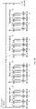
- FIG. 9A is a schematic diagram of a period in which RMSI is transmitted by using different beams according to an embodiment of the present invention.
- a beam 1, a beam 2, a beam 3, and a beam 4 respectively correspond to transmission periods t1, t2, t3, and t4.
- FIG. 9B is a schematic diagram of a period in which RMSI is transmitted by using different beams in one TTI.
- FIG. 9C is a schematic diagram of transmission performed by using different beams that have a time offset relative to a period location. An example is used for description.
- a period in which repeated RMSI is transmitted by using a different beam is 10 ms, and a period location of the period of repeated transmission is a subframe 5 of each frame, to be specific, the RMSI is transmitted in a subframe 5 of a frame 0, the RMSI is transmitted in a subframe 5 of a frame 1, and the RMSI is transmitted in a subframe 5 of a frame 2.
- a time offset of a first beam is -1 subframe
- a time offset of a second beam is 1 subframe
- a time offset of a third beam is 0, a location at which the RMSI is transmitted in the frame 0 is a subframe 4, a transmission location of the RMSI in the frame 1 is a subframe 6, a transmission location of the RMSI in the frame 2 is the subframe 5.
- function modules of a transmit end device or a receive end device may be divided based on the foregoing method examples.
- function modules may be divided based on functions, or two or more functions may be integrated into one processing module.
- the integrated module may be implemented in a form of hardware, or may be implemented in a form of a software function module.
- the module division in the embodiments of this application is an example, and is merely logical function division. There may be another division manner in an actual implementation. The following performs description by using an example in which function modules are divided based on functions.
- FIG. 10 is a schematic structural diagram of an information sending apparatus 10 according to an embodiment of the present invention.
- the information sending apparatus 10 may be a network device or a chip.
- the information sending apparatus 10 may include a processing unit 102 and a sending unit 101. Detailed descriptions of the units are as follows:
- the sending unit 101 is further configured to send indication information to the terminal device, where the indication information is used to indicate the PBCH period.
- FIG. 11 is a schematic structural diagram of another information sending apparatus 20 according to an embodiment of the present invention.
- the information sending apparatus 20 may be a network device or a chip.
- the information sending apparatus 20 may include a processing unit 202 and a sending unit 201. Detailed descriptions of the units are as follows:
- the sending unit 201 is further configured to send indication information to the terminal device, where the indication information is used to indicate the PBCH period.
- FIG. 12 is a schematic structural diagram of an information sending apparatus 30 according to an embodiment of the present invention.
- the information sending apparatus 30 may be a network device or a chip.
- the information sending apparatus 30 may include a processing unit 302 and a sending unit 301. Detailed descriptions of the units are as follows:
- the sending unit 301 is further configured to send indication information to the terminal device, where the indication information is used to indicate the PBCH period.
- the sending unit 301 is further configured to indicate a value of X by using signaling.
- FIG. 13 is a schematic structural diagram of an information sending apparatus 40 according to an embodiment of the present invention.
- the information sending apparatus 40 may be a network device or a chip.
- the information sending apparatus 40 may include a processing unit 402 and a sending unit 401. Detailed descriptions of the units are as follows:
- the sending unit 401 is further configured to send indication information to the terminal device, where the indication information is used to indicate the PBCH period.
- FIG. 14 is a schematic structural diagram of an information receiving apparatus 50 according to an embodiment of the present invention.
- the information receiving apparatus 50 may be a terminal device or a chip.
- the information receiving apparatus 50 may include a processing unit 501 and a receiving unit 502. Detailed descriptions of the units are as follows:
- the receiving unit 502 is further configured to receive indication information sent by the network device, where the indication information is used to indicate the PBCH period.
- FIG. 15 is a schematic structural diagram of an information receiving apparatus 60 according to an embodiment of the present invention.
- the information receiving apparatus 60 may be a terminal device or a chip.
- the information receiving apparatus 60 may include a processing unit 601 and a receiving unit 602. Detailed descriptions of the units are as follows:
- the receiving unit 602 is further configured to receive indication information sent by the network device, where the indication information is used to indicate the PBCH period.
- FIG. 16 is a schematic structural diagram of an information receiving apparatus 70 according to an embodiment of the present invention.
- the information receiving apparatus 70 may be a terminal device or a chip.
- the information receiving apparatus 70 may include a processing unit 701 and a receiving unit 702. Detailed descriptions of the units are as follows:
- the receiving unit 702 is further configured to receive indication information sent by the network device, where the indication information is used to indicate the PBCH period.
- FIG. 17 is a schematic structural diagram of an information receiving apparatus 80 according to an embodiment of the present invention.
- the information receiving apparatus 80 may be a terminal device or a chip.
- the information receiving apparatus 80 may include a processing unit 801 and a receiving unit 802. Detailed descriptions of the units are as follows:
- the receiving unit 802 is further configured to receive indication information sent by the network device, where the indication information is used to indicate the PBCH period.
- FIG. 18 is a simplified schematic structural diagram of a terminal device.
- the terminal device includes a processor, a memory, a radio frequency circuit, an antenna, and an input/output apparatus.
- the processor is mainly configured to: process a communication protocol and communication data, control the terminal device, execute a software program, process data of the software program, and the like.
- the memory is mainly configured to store the software program and the data.
- the radio frequency circuit is mainly configured to: perform conversion between a baseband signal and a radio frequency signal, and process the radio frequency signal.
- the antenna is mainly configured to receive and transmit a radio frequency signal in a form of an electromagnetic wave.
- the input/output apparatus such as a touchscreen, a display screen, or a keyboard, is mainly configured to: receive data entered by a user, and output data to the user. It should be noted that some types of terminal devices may not have the input/output apparatus.
- the processor When data needs to be sent, the processor performs baseband processing on the to-be-sent data, and then outputs a baseband signal to the radio frequency circuit.
- the radio frequency circuit performs radio frequency processing on the baseband signal, and then sends the radio frequency signal in a form of an electromagnetic wave by using the antenna.
- the radio frequency circuit receives a radio frequency signal by using the antenna, converts the radio frequency signal into a baseband signal, and outputs the baseband signal to the processor.
- the processor converts the baseband signal into data, and processes the data.
- FIG. 18 shows only one memory and one processor. In an actual terminal product, there may be one or more processors and one or more memories.
- the memory may also be referred to as a storage medium, a storage device, or the like.
- the memory may be disposed independent of the processor, or may be integrated with the processor. This is not limited in this embodiment of this application.
- the antenna and the radio frequency circuit that have a transceiving function may be considered as a transceiver unit of the terminal device, and the processor that has a processing function may be considered as a processing unit of the terminal device.
- the terminal device includes a transceiver unit 1801 and a processing unit 1802.
- the transceiver unit may also be referred to as a transceiver, a transceiver apparatus, or the like.
- the processing unit may also be referred to as a processor, a processing board, a processing module, a processing apparatus, or the like.
- the processing unit may be a central processing unit (CPU), a network processor (NP), or a combination of a CPU and an NP.
- the processing unit may further include a hardware chip.
- the hardware chip may be an application-specific integrated circuit ASIC), a programmable logic device (PLD), or a combination thereof.
- the PLD may be a complex programmable logic device (CPLD), a field-programmable gate array (FPGA), generic array logic (GAL), or any combination thereof.
- CPLD complex programmable logic device
- FPGA field-programmable gate array
- GAL generic array logic
- a component for implementing a receiving function in the transceiver unit 1801 may be considered as a receiving unit
- a component for implementing a sending function in the transceiver unit 1801 may be considered as a sending unit.
- the transceiver unit 1801 includes the receiving unit and the sending unit.
- the transceiver unit may also be sometimes referred to as a transceiver, a transceiver circuit, or the like.
- the receiving unit may also be sometimes referred to as a receiver, a receiver circuit, or the like.
- the sending unit may also be sometimes referred to as a transmitter, a transmitter circuit, or the like.
- the information receiving apparatus is a chip
- the chip includes a transceiver unit and a processing unit.
- the transceiver unit may be an input/output circuit or a communications interface.
- the processing unit is a processor, a microprocessor, or an integrated circuit integrated on the chip.
- FIG. 19 is a simplified schematic structural diagram of a base station.
- the base station includes a part 1901 and a part 1902.
- the part 1901 is mainly configured to: send and receive a radio frequency signal, and convert the radio frequency signal and a baseband signal.
- the part 1902 is mainly configured to: perform baseband processing, control the base station, and the like.
- the part 1901 may be generally referred to as a transceiver unit, a transceiver, a transceiver circuit, or the like.
- the part 1902 is generally a control center of the base station, and may be generally referred to as a processing unit, configured to control the base station to perform steps performed by a transmit end device in the foregoing figures. For details, refer to descriptions of the foregoing related parts.
- a transceiver unit in the part 1901 may also be referred to as a transceiver, a transceiver, or the like, and includes an antenna and a radio frequency unit.
- the radio frequency unit is mainly configured to perform radio frequency processing.
- a component for implementing a receiving function in the part 1901 may be considered as a receiving unit, and a component for implementing a sending function may be considered as a sending unit.
- the part 1901 includes the receiving unit and the sending unit.
- the receiving unit may also be referred to as a receiver, a receiver circuit, or the like.
- the sending unit may also be referred to as a transmitter, a transmitter circuit, or the like.
- the part 1902 may include one or more boards. Each board may include one or more processors and one or more memories.
- the processor is configured to read and execute a program in the memory, to implement a baseband processing function and controlling of the base station. If there are a plurality of boards, the boards may be interconnected to improve a processing capability.
- a plurality of boards may share one or more processors, or a plurality of boards share one or more memories, or a plurality of boards simultaneously share one or more processors.
- the information sending apparatus may be a chip, and the chip includes a transceiver unit and a processing unit.
- the transceiver unit may be an input/output circuit or a communications interface of the chip.
- the processing unit is a processor, a microprocessor, or an integrated circuit integrated on the chip.
- the chip may be applied to the foregoing network device, and supports the network device in performing the foregoing methods.
- All or some of the foregoing embodiments may be implemented by using software, hardware, firmware, or any combination thereof.
- a software program is used to implement the embodiments, the embodiments may be all or partially implemented in a form of a computer program product.
- the computer program product includes one or more computer instructions.
- the computer program instructions When the computer program instructions are loaded and executed on a computer, the procedures or functions according to the embodiments of this application are all or partially generated.
- the computer may be a general-purpose computer, a dedicated computer, a computer network, or another programmable apparatus.
- the computer instructions may be stored in a computer readable storage medium or may be transmitted from a computer readable storage medium to another computer readable storage medium.
- the computer instructions may be transmitted from a website, computer, server, or data center to another website, computer, server, or data center in a wired (for example, a coaxial cable, an optical fiber, or a digital subscriber line (DSL)) or wireless (for example, infrared, radio, or microwave) manner.
- the computer readable storage medium may be any usable medium accessible by a computer, or a data storage device, such as a server or a data center, integrating one or more usable media.
- the usable medium may be a magnetic medium (for example, a floppy disk, a hard disk, or a magnetic tape), an optical medium (for example, a DVD), a semiconductor medium (for example, a solid state disk (SSD)), or the like.
- An embodiment of the present invention further provides a chip.
- the chip includes a communications interface and a processor.
- the processor is configured to control the communications interface to receive or send a signal, and is configured to process a signal received by the communications interface or generate a signal to be sent by the communications interface.
- the processor is configured to perform procedures or steps on a terminal side in the information sending and receiving methods provided in the foregoing method embodiments, or the processor is configured to perform procedures or steps on a network device side in the information sending and receiving methods provided in the foregoing method embodiments.
- the chip further includes a storage module, and the storage module stores an instruction.
- the processor reads the instruction stored in the storage module to execute a related operation, and control the communications interface to perform a related transmitting and receiving operation.
- sequence numbers of the foregoing processes do not mean execution sequences.
- the execution sequences of the processes should be determined based on functions and internal logic of the processes, and should not be construed as any limitation on the implementation processes of the embodiments of the present invention.
- the disclosed system, apparatus, and method may be implemented in other manners.
- the described apparatus embodiment is merely an example.
- the unit division is merely logical function division and may be other division in actual implementation.
- a plurality of units or components may be combined or integrated into another system, or some features may be ignored or not performed.
- the displayed or discussed mutual couplings or direct couplings or communication connections may be implemented by using some interfaces.
- the indirect couplings or communication connections between the apparatuses or units may be implemented in electronic, mechanical, or other forms.
- the units described as separate parts may or may not be physically separate, and parts displayed as units may or may not be physical units, may be located in one position, or may be distributed on a plurality of network units. Some or all of the units may be selected based on actual requirements to achieve the objectives of the solutions of the embodiments.
- All or some of the foregoing embodiments may be implemented by using software, hardware, firmware, or any combination thereof.
- the embodiments may be all or partially implemented in a form of a computer program product.
- the computer program product includes one or more computer instructions.
- the computer program instructions When the computer program instructions are loaded and executed on a computer, the procedures or functions according to the embodiments of the present invention are all or partially generated.
- the computer may be a general-purpose computer, a dedicated computer, a computer network, or another programmable apparatus.
- the computer instructions may be stored in a computer readable storage medium, or may be transmitted by using the computer readable storage medium.
- the computer instructions may be transmitted from a website, computer, server, or data center to another website, computer, server, or data center in a wired (for example, a coaxial cable, an optical fiber, or a digital subscriber line (DSL)) or wireless (for example, infrared, radio, or microwave) manner.
- the computer readable storage medium may be any usable medium accessible by a computer, or a data storage device, such as a server or a data center, integrating one or more usable media.
- the usable medium may be a magnetic medium (for example, a floppy disk, a hard disk, or a magnetic tape), an optical medium (for example, a digital versatile disc (DVD)), a semiconductor medium (for example, a solid state disk (SSD)), or the like.
- a magnetic medium for example, a floppy disk, a hard disk, or a magnetic tape
- an optical medium for example, a digital versatile disc (DVD)
- DVD digital versatile disc
- semiconductor medium for example, a solid state disk (SSD)
- the program may be stored in a computer readable storage medium. When the program runs, the procedures of the foregoing method embodiments may be performed.
- the foregoing storage medium includes any medium that can store program code, such as a read-only memory (ROM), a random access memory (RAM), a magnetic disk, or an optical disc.
Landscapes
- Engineering & Computer Science (AREA)
- Signal Processing (AREA)
- Computer Networks & Wireless Communication (AREA)
- Quality & Reliability (AREA)
- Mobile Radio Communication Systems (AREA)
Claims (15)
- Informationssendeeinrichtung (20), die Folgendes umfasst:eine Verarbeitungseinheit (202), die konfiguriert ist, um basierend auf einer Periode eines physischen Broadcast-Kanals (physical broadcast channel - PBCH), wobei die Periode des PBCH eine Periode eines
Synchronisationsblocksignalbündelsatzes (synchronization block burst set - SS block burst set) ist, eine Periode X zum Senden eines Systeminformationsblocks SIB1 zu bestimmen; undeine Sendeeinheit (201), die konfiguriert ist, um wenigstens einen SIB1 innerhalb einer Übertragungszeitintervall(transmission time interval - TTI)-Periode durch Verwenden des X als eine Periode an ein Endgerät zu senden, wobei die TTI-Periode ein voreingestellter Wert von 160 ms ist, und die Periode X die gleiche wie eine Periode des PBCH ist, wobei die Periode des PBCH ein voreingestellter Wert von 5 ms, 10 ms, 20 ms, 40 ms oder 80 ms ist. - Einrichtung (20) nach Anspruch 1, wobei die Sendeeinheit (201) konfiguriert ist, um die wenigstens eine SIB1 durch Verwenden wenigstens eines Strahl- oder Antennenanschlusses an das Endgerät zu senden; und eine Anzahl des wenigstens einen Strahl- oder Antennenanschlusses die gleiche wie eine Anzahl von Strahl- oder Antennenanschlüssen zum Senden des wenigstens einen Synchronisationssignalblocks (synchronization signal block - SS-Block) ist.
- Einrichtung (20) nach Anspruch 2, wobei der wenigstens eine Antennenanschluss, der den wenigstens einen SIB1 sendet, und der wenigstens eine SS-Block eine quasikolokalisierte (quasi co-located - QCL-)Beziehung aufweisen.
- Einrichtung (20) nach Anspruch 2 oder 3, wobei in jeder Periode X die Sendeeinheit (201) konfiguriert ist, um den wenigstens einen SIB1, der den Zeit-Frequenz-Ressourcen der verschiedenen SS-Blöcke in dem wenigstens einen SS-Block entspricht, periodisch zu senden; in einer gleichen Periode X Zeitintervalle, in denen SIB1s gesendet werden, die den Zeit-Frequenz-Ressourcen angrenzender SS-Blöcke entsprechen, gleich sind, und eine Startposition des Zeitintervalls durch Verwenden eines Mastersignalblocks MIB konfiguriert wird.
- Einrichtung (20) nach Anspruch 2 oder 3, wobei es in jeder Periode X einen Zeitversatz zwischen einer Zeitposition eines SIB1, der der Zeit-Frequenz-Ressource jedes SS-Blocks in dem wenigstens einen SS-Block entspricht, in Bezug auf die Startposition des Zeitintervalls, in dem das SIB1 gesendet wird, gibt.
- Einrichtung (20) nach einem der Ansprüche 1 bis 5, wobei SIB1-Kombinationen, die Zeit-Frequenz-Ressourcen von mehreren SS-Blöcken in dem wenigstens einen SS-Block entsprechen, die gleiche Startposition des Zeitintervalls aufweisen.
- Einrichtung (20) nach einem der Ansprüche 1 bis 6, wobei die Sendeeinheit (201) ferner konfiguriert ist, um einen Wert der Periode X durch Verwenden einer Signalisierung anzuzeigen.
- Informationsempfangseinrichtung, die Folgendes umfasst:eine Verarbeitungseinheit (601), die konfiguriert ist, um ein erstes Mal zu bestimmen, um einen oder mehrere Systeminformationsblöcke (SIB1s) gemäß einer Periode eines physischen Broadcast-Kanals (PBCH) (S501) zu empfangen, wobei der eine oder die mehreren SIB1s sind, die von einer Netzwerkvorrichtung in einer Übertragungszeitintervall(TTI)-Periode durch Verwenden von X als eine Periode (S502) empfangen werden; die TTI-Periode ein voreingestellter Wert von 160 ms ist und die Periode X die gleiche ist wie die Periode des PBCH, wobei die Periode des PBCH ein voreingestellter Wert von 5 ms, 10 ms, 20 ms, 40 ms oder 80 ms ist; undeine Empfangseinheit (602), die konfiguriert ist, um den einen oder die mehreren SIB1s gemäß der ersten Zeit zu empfangen (S503).
- Einrichtung (60) nach Anspruch 8, wobei die Empfangseinheit (602) konfiguriert ist, um den einen oder die mehreren SIB1s in wenigstens einem SIB1 zu empfangen, der durch die Netzwerkvorrichtung durch Verwenden wenigstens eines Strahl- oder Antennenanschlusses gesendet wird.
- Einrichtung (60) nach Anspruch 9, wobei die Empfangseinheit (602) konfiguriert ist, um den einen oder die mehreren SIB1s basierend auf wenigstens einem Synchronisationssignalblock (SS-Block) zu empfangen, der der ersten Zeit entspricht; eine Anzahl von Strahl- oder Antennenanschlüssen des wenigstens einen Synchronisationssignalblocks (SS-Blocks) in der PBCH-Periode die gleiche wie eine Anzahl des wenigstens einen Strahl- oder Antennenanschlusses ist, die dem wenigstens einen SIB1 in der X-Periode entspricht.
- Einrichtung (60) nach Anspruch 9 oder 10, wobei in einer gleichen Periode X, wobei Zeitintervalle von SIB1s, die den Zeit-Frequenz-Ressourcen angrenzender SS-Blöcke in dem wenigstens einen SS-Block gleich sind, und eine Startposition des Zeitintervalls durch Verwenden eines Mastersignalblocks (MIB) konfiguriert wird.
- Einrichtung (60) nach Anspruch 2 oder 3, wobei es in jeder Periode X einen Zeitversatz zwischen einer Zeitposition eines SIB1, der der Zeit-Frequenz-Ressource jedes SS-Blocks in dem wenigstens einen SS-Block entspricht, in Bezug auf die Startposition des Zeitintervalls des SIB1 in der Periode X gibt.
- Einrichtung (60) nach einem der Ansprüche 8 bis 12, wobei SIB1-Kombinationen, die Zeit-Frequenz-Ressourcen von mehreren SS-Blöcken in dem wenigstens einen SS-Block entsprechen, die gleiche Startposition des Zeitintervalls aufweisen.
- Einrichtung (60) nach einem der Ansprüche 8 bis 13, wobei die Empfangseinheit (602) ferner konfiguriert ist, um einen Wert der Periode X durch Empfangen der Signalisierung zu bestimmen.
- Informationsempfangsverfahren, das Folgendes umfasst:Bestimmen, durch ein Endgerät, eines ersten Mals, um einen oder mehrere Systeminformationsblöcke (SIB1s) gemäß einer Periode eines physischen Broadcast-Kanals (PBCH) (S501) zu empfangen, wobei der eine oder die mehreren SIB1s sind, die von einer Netzwerkvorrichtung in einer Übertragungszeitintervall(TTI)-Periode durch Verwenden von X als eine Periode (S502) empfangen werden; die TTI-Periode ein voreingestellter Wert von 160 ms ist und die Periode X die gleiche ist wie die Periode des PBCH, wobei die Periode des PBCH ein voreingestellter Wert von 5 ms, 10 ms, 20 ms, 40 ms oder 80 ms ist; undEmpfangen, durch ein Endgerät, des einen oder der mehreren SIB1s gemäß der ersten Zeit (S503).
Priority Applications (1)
| Application Number | Priority Date | Filing Date | Title |
|---|---|---|---|
| EP22166016.0A EP4087172A1 (de) | 2017-08-11 | 2018-08-09 | Verfahren und vorrichtungen zum senden und empfangen von informationen |
Applications Claiming Priority (2)
| Application Number | Priority Date | Filing Date | Title |
|---|---|---|---|
| CN201710690892.6A CN109391454B (zh) | 2017-08-11 | 2017-08-11 | 一种信息发送、接收方法及装置 |
| PCT/CN2018/099624 WO2019029621A1 (zh) | 2017-08-11 | 2018-08-09 | 一种信息发送、接收方法及装置 |
Related Child Applications (2)
| Application Number | Title | Priority Date | Filing Date |
|---|---|---|---|
| EP22166016.0A Division EP4087172A1 (de) | 2017-08-11 | 2018-08-09 | Verfahren und vorrichtungen zum senden und empfangen von informationen |
| EP22166016.0A Division-Into EP4087172A1 (de) | 2017-08-11 | 2018-08-09 | Verfahren und vorrichtungen zum senden und empfangen von informationen |
Publications (3)
| Publication Number | Publication Date |
|---|---|
| EP3667986A1 EP3667986A1 (de) | 2020-06-17 |
| EP3667986A4 EP3667986A4 (de) | 2020-08-12 |
| EP3667986B1 true EP3667986B1 (de) | 2022-05-04 |
Family
ID=65270905
Family Applications (2)
| Application Number | Title | Priority Date | Filing Date |
|---|---|---|---|
| EP18843882.4A Active EP3667986B1 (de) | 2017-08-11 | 2018-08-09 | Verfahren und vorrichtung für informationsübertragung und -empfang |
| EP22166016.0A Pending EP4087172A1 (de) | 2017-08-11 | 2018-08-09 | Verfahren und vorrichtungen zum senden und empfangen von informationen |
Family Applications After (1)
| Application Number | Title | Priority Date | Filing Date |
|---|---|---|---|
| EP22166016.0A Pending EP4087172A1 (de) | 2017-08-11 | 2018-08-09 | Verfahren und vorrichtungen zum senden und empfangen von informationen |
Country Status (4)
| Country | Link |
|---|---|
| US (1) | US11659527B2 (de) |
| EP (2) | EP3667986B1 (de) |
| CN (2) | CN109391454B (de) |
| WO (1) | WO2019029621A1 (de) |
Families Citing this family (17)
| Publication number | Priority date | Publication date | Assignee | Title |
|---|---|---|---|---|
| CN109787730B (zh) * | 2017-11-14 | 2020-07-03 | 电信科学技术研究院 | 一种资源配置方法及装置、计算机存储介质 |
| AU2017440250B2 (en) | 2017-11-14 | 2022-10-06 | Guangdong Oppo Mobile Telecommunications Corp., Ltd. | Wireless communication method and device |
| EP3713327B8 (de) | 2017-11-14 | 2023-05-10 | Beijing Xiaomi Mobile Software Co., Ltd. | Verfahren zur anzeige der frequenzdomäneninformation eines gemeinsamen steuerressourcensatzes von verbleibenden minimalen systeminformationen |
| US11770781B2 (en) * | 2017-11-15 | 2023-09-26 | Koninklijke Philips N.V. | Method and device for indicating period information of common control resource set of remaining key system information |
| CN109451799B (zh) | 2017-11-16 | 2021-07-06 | 北京小米移动软件有限公司 | 剩余关键系统信息的公共控制资源集合的时域信息指示方法 |
| ES2956333T3 (es) * | 2018-01-02 | 2023-12-19 | Ericsson Telefon Ab L M | Método, dispositivo de red y dispositivo terminal para la información mínima restante del sistema |
| US10912047B2 (en) * | 2018-03-29 | 2021-02-02 | Lg Electronics Inc. | Method and apparatus for transmitting and receiving system information |
| KR102484056B1 (ko) * | 2018-09-28 | 2023-01-02 | 지티이 코포레이션 | 비-지상 위성 네트워크들에 대한 추적 영역 업데이트 및 페이징 방법 |
| CN113596877B (zh) * | 2019-02-15 | 2024-09-06 | 维沃移动通信有限公司 | 一种测量处理方法、参数配置方法、终端和网络设备 |
| JP7216186B2 (ja) | 2019-03-12 | 2023-01-31 | 株式会社Nttドコモ | 端末、無線通信方法、基地局及びシステム |
| CN111918392B (zh) * | 2019-05-08 | 2023-06-27 | 中国移动通信有限公司研究院 | 信息的指示方法、检测方法、网络设备及终端 |
| CN114902741B (zh) * | 2019-12-31 | 2025-05-06 | 华为技术有限公司 | 一种系统信息的传递方法和装置 |
| WO2021142692A1 (en) * | 2020-01-16 | 2021-07-22 | Qualcomm Incorporated | Bandwidth part assignment in wireless communication systems |
| US12413279B2 (en) * | 2020-07-31 | 2025-09-09 | Qualcomm Incorporated | Beam specific RMSI transmission |
| CN114827942B (zh) * | 2021-01-29 | 2026-01-23 | 伊姆西Ip控股有限责任公司 | 数据传输的方法、电子设备和计算机程序产品 |
| US12413340B2 (en) * | 2022-09-14 | 2025-09-09 | AT&T Technical Services Company, Inc. | Repeating system information messages delivery in advanced networks |
| US12538181B2 (en) | 2022-09-14 | 2026-01-27 | AT&T Technical Services Company, Inc. | Optional requesting of system information delivery in advanced networks |
Family Cites Families (19)
| Publication number | Priority date | Publication date | Assignee | Title |
|---|---|---|---|---|
| CN101651988B (zh) * | 2008-08-14 | 2013-08-14 | 华为技术有限公司 | 一种系统信息获取方法、通信系统以及移动终端 |
| WO2012042295A1 (en) * | 2010-09-27 | 2012-04-05 | Nokia Corporation | Audio scene apparatuses and methods |
| US9107186B2 (en) * | 2011-02-23 | 2015-08-11 | Qualcomm Incorporated | Carrier aggregation for evolved multimedia broadcast multicast service enhancement |
| CN104782185A (zh) * | 2012-09-13 | 2015-07-15 | Lg电子株式会社 | 在无线通信系统中获取系统信息的操作方法及支持该方法的设备 |
| CN105745848B (zh) * | 2013-11-01 | 2019-07-05 | 三星电子株式会社 | 用于lte先进的增强覆盖发送的方法和装置 |
| CN105723765B (zh) * | 2014-10-20 | 2019-12-06 | 华为技术有限公司 | 一种系统信息的传输方法、装置及系统 |
| WO2016119130A1 (zh) * | 2015-01-27 | 2016-08-04 | 华为技术有限公司 | 一种系统信息获取方法、发送方法、ue及基站 |
| JP2018041995A (ja) * | 2015-01-28 | 2018-03-15 | シャープ株式会社 | 端末装置、基地局装置および方法 |
| CN106879040B (zh) * | 2015-12-10 | 2021-03-16 | 上海诺基亚贝尔股份有限公司 | 无线网络中提供和获取小区系统信息的方法、装置及设备 |
| CN106921468B (zh) * | 2015-12-28 | 2020-05-22 | 中兴通讯股份有限公司 | 一种信息传输方法及装置 |
| US11296837B2 (en) | 2016-01-28 | 2022-04-05 | Qualcomm Incorporated | Physical broadcast channel (PBCH) transmission and reception on a shared communication medium |
| US10757707B2 (en) * | 2016-06-03 | 2020-08-25 | Samsung Electronics Co., Ltd. | Method and apparatus for communicating in wireless communication system |
| WO2018016907A1 (ko) * | 2016-07-21 | 2018-01-25 | 엘지전자 주식회사 | 무선 통신 시스템에서 하향링크 제어 정보를 송신 또는 수신하는 방법 및 이를 위한 장치 |
| EP3618506B1 (de) * | 2017-04-28 | 2022-08-17 | NTT DoCoMo, Inc. | Benutzerendgerät und drahtloskommunikationsverfahren |
| WO2018203672A1 (en) * | 2017-05-02 | 2018-11-08 | Samsung Electronics Co., Ltd. | Method and apparatus of initial access in next generation cellular networks |
| CN110603863B (zh) * | 2017-05-02 | 2023-03-21 | 株式会社Ntt都科摩 | 终端、基站装置和通信方法 |
| US10856332B2 (en) * | 2017-06-23 | 2020-12-01 | Mediatek Inc. | Method and apparatus for random access channel procedure in wireless communication system |
| US11395338B2 (en) * | 2017-07-12 | 2022-07-19 | Samsung Electronics Co., Ltd. | Method and apparatus for control resource set configuration for 5G next radio system |
| US10880927B2 (en) * | 2017-11-17 | 2020-12-29 | Qualcomm Incorporated | Mapping rules between synchronization signal blocks and random access channel resources |
-
2017
- 2017-08-11 CN CN201710690892.6A patent/CN109391454B/zh active Active
- 2017-08-11 CN CN202111082978.3A patent/CN113890706B/zh active Active
-
2018
- 2018-08-09 WO PCT/CN2018/099624 patent/WO2019029621A1/zh not_active Ceased
- 2018-08-09 EP EP18843882.4A patent/EP3667986B1/de active Active
- 2018-08-09 EP EP22166016.0A patent/EP4087172A1/de active Pending
-
2020
- 2020-02-10 US US16/786,535 patent/US11659527B2/en active Active
Also Published As
| Publication number | Publication date |
|---|---|
| US11659527B2 (en) | 2023-05-23 |
| EP3667986A1 (de) | 2020-06-17 |
| WO2019029621A1 (zh) | 2019-02-14 |
| EP4087172A1 (de) | 2022-11-09 |
| CN113890706B (zh) | 2022-09-09 |
| CN109391454B (zh) | 2021-09-14 |
| US20200178253A1 (en) | 2020-06-04 |
| CN109391454A (zh) | 2019-02-26 |
| CN113890706A (zh) | 2022-01-04 |
| EP3667986A4 (de) | 2020-08-12 |
Similar Documents
| Publication | Publication Date | Title |
|---|---|---|
| US11659527B2 (en) | Apparatus for sending information regarding RMSI period | |
| US11751166B2 (en) | Quasi co-location of antenna ports used to transmit paging message and synchronization signals | |
| US10849166B2 (en) | Random access procedures in Next Gen networks | |
| KR102586209B1 (ko) | 진보된 무선 시스템의 re 매핑 및 레이트 매칭 방법 및 장치 | |
| CN110168945B (zh) | 在寻呼指示与寻呼信息的传输之间提供寻呼响应 | |
| US10764909B2 (en) | System and method for sectorized transmission in a wireless network | |
| CN109565808B (zh) | 用于各种dl-ul对应关系状态的dl同步波束信息的rach传达 | |
| US9717094B2 (en) | Method and apparatus for device-to-device communication | |
| CN118369963A (zh) | 用于唤醒小区的信令 | |
| US20160338110A1 (en) | Method for configuring physical channel, base station and user equipment | |
| US20210135734A1 (en) | Systems and methods for joint beam sweep configuration in 5g networks | |
| CN110301159A (zh) | 用于共享频谱的发现和随机接入 | |
| CN110199538A (zh) | 基站波束扫掠期间的数据传输 | |
| CN111684862A (zh) | Nr-u上的prach配置 | |
| CN118337347A (zh) | 确定寻呼时机资源 | |
| CN110999504A (zh) | 利用广播/多播接收的空间lbt | |
| CN114667705A (zh) | 用于两步随机接入信道(rach)的物理上行链路共享信道(pusch)时机验证的系统和方法 | |
| WO2018188652A1 (zh) | 随机接入及响应方法、终端设备、网络设备 | |
| EP3566501B1 (de) | Explizite konfiguration von funkruf und steuerkanal in systeminformationen | |
| WO2024032227A1 (zh) | 一种通信方法及装置 | |
| US20250365057A1 (en) | Method and apparatus for sidelink communication | |
| US20250106817A1 (en) | Transmitting and receiving a paging notification or alert | |
| US20250219707A1 (en) | Method, network controlled repeater, and access network node | |
| US20240146592A1 (en) | Synchronization Signal Block Enhancement For Additional Numerologies | |
| TWI924746B (zh) | 用於非地面通訊的同步信號區塊監測時機設計 |
Legal Events
| Date | Code | Title | Description |
|---|---|---|---|
| STAA | Information on the status of an ep patent application or granted ep patent |
Free format text: STATUS: THE INTERNATIONAL PUBLICATION HAS BEEN MADE |
|
| PUAI | Public reference made under article 153(3) epc to a published international application that has entered the european phase |
Free format text: ORIGINAL CODE: 0009012 |
|
| STAA | Information on the status of an ep patent application or granted ep patent |
Free format text: STATUS: REQUEST FOR EXAMINATION WAS MADE |
|
| 17P | Request for examination filed |
Effective date: 20200310 |
|
| AK | Designated contracting states |
Kind code of ref document: A1 Designated state(s): AL AT BE BG CH CY CZ DE DK EE ES FI FR GB GR HR HU IE IS IT LI LT LU LV MC MK MT NL NO PL PT RO RS SE SI SK SM TR |
|
| AX | Request for extension of the european patent |
Extension state: BA ME |
|
| A4 | Supplementary search report drawn up and despatched |
Effective date: 20200713 |
|
| RIC1 | Information provided on ipc code assigned before grant |
Ipc: H04L 5/00 20060101AFI20200707BHEP Ipc: H04W 72/04 20090101ALI20200707BHEP |
|
| DAV | Request for validation of the european patent (deleted) | ||
| DAX | Request for extension of the european patent (deleted) | ||
| RIC1 | Information provided on ipc code assigned before grant |
Ipc: H04W 72/04 20090101ALI20211019BHEP Ipc: H04L 5/00 20060101AFI20211019BHEP |
|
| GRAP | Despatch of communication of intention to grant a patent |
Free format text: ORIGINAL CODE: EPIDOSNIGR1 |
|
| STAA | Information on the status of an ep patent application or granted ep patent |
Free format text: STATUS: GRANT OF PATENT IS INTENDED |
|
| INTG | Intention to grant announced |
Effective date: 20211126 |
|
| GRAS | Grant fee paid |
Free format text: ORIGINAL CODE: EPIDOSNIGR3 |
|
| GRAA | (expected) grant |
Free format text: ORIGINAL CODE: 0009210 |
|
| STAA | Information on the status of an ep patent application or granted ep patent |
Free format text: STATUS: THE PATENT HAS BEEN GRANTED |
|
| AK | Designated contracting states |
Kind code of ref document: B1 Designated state(s): AL AT BE BG CH CY CZ DE DK EE ES FI FR GB GR HR HU IE IS IT LI LT LU LV MC MK MT NL NO PL PT RO RS SE SI SK SM TR |
|
| REG | Reference to a national code |
Ref country code: GB Ref legal event code: FG4D |
|
| REG | Reference to a national code |
Ref country code: CH Ref legal event code: EP |
|
| REG | Reference to a national code |
Ref country code: AT Ref legal event code: REF Ref document number: 1490311 Country of ref document: AT Kind code of ref document: T Effective date: 20220515 |
|
| REG | Reference to a national code |
Ref country code: IE Ref legal event code: FG4D Ref country code: DE Ref legal event code: R096 Ref document number: 602018035150 Country of ref document: DE |
|
| REG | Reference to a national code |
Ref country code: LT Ref legal event code: MG9D |
|
| REG | Reference to a national code |
Ref country code: NL Ref legal event code: MP Effective date: 20220504 |
|
| REG | Reference to a national code |
Ref country code: AT Ref legal event code: MK05 Ref document number: 1490311 Country of ref document: AT Kind code of ref document: T Effective date: 20220504 |
|
| PG25 | Lapsed in a contracting state [announced via postgrant information from national office to epo] |
Ref country code: SE Free format text: LAPSE BECAUSE OF FAILURE TO SUBMIT A TRANSLATION OF THE DESCRIPTION OR TO PAY THE FEE WITHIN THE PRESCRIBED TIME-LIMIT Effective date: 20220504 Ref country code: PT Free format text: LAPSE BECAUSE OF FAILURE TO SUBMIT A TRANSLATION OF THE DESCRIPTION OR TO PAY THE FEE WITHIN THE PRESCRIBED TIME-LIMIT Effective date: 20220905 Ref country code: NO Free format text: LAPSE BECAUSE OF FAILURE TO SUBMIT A TRANSLATION OF THE DESCRIPTION OR TO PAY THE FEE WITHIN THE PRESCRIBED TIME-LIMIT Effective date: 20220804 Ref country code: NL Free format text: LAPSE BECAUSE OF FAILURE TO SUBMIT A TRANSLATION OF THE DESCRIPTION OR TO PAY THE FEE WITHIN THE PRESCRIBED TIME-LIMIT Effective date: 20220504 Ref country code: LT Free format text: LAPSE BECAUSE OF FAILURE TO SUBMIT A TRANSLATION OF THE DESCRIPTION OR TO PAY THE FEE WITHIN THE PRESCRIBED TIME-LIMIT Effective date: 20220504 Ref country code: HR Free format text: LAPSE BECAUSE OF FAILURE TO SUBMIT A TRANSLATION OF THE DESCRIPTION OR TO PAY THE FEE WITHIN THE PRESCRIBED TIME-LIMIT Effective date: 20220504 Ref country code: GR Free format text: LAPSE BECAUSE OF FAILURE TO SUBMIT A TRANSLATION OF THE DESCRIPTION OR TO PAY THE FEE WITHIN THE PRESCRIBED TIME-LIMIT Effective date: 20220805 Ref country code: FI Free format text: LAPSE BECAUSE OF FAILURE TO SUBMIT A TRANSLATION OF THE DESCRIPTION OR TO PAY THE FEE WITHIN THE PRESCRIBED TIME-LIMIT Effective date: 20220504 Ref country code: ES Free format text: LAPSE BECAUSE OF FAILURE TO SUBMIT A TRANSLATION OF THE DESCRIPTION OR TO PAY THE FEE WITHIN THE PRESCRIBED TIME-LIMIT Effective date: 20220504 Ref country code: BG Free format text: LAPSE BECAUSE OF FAILURE TO SUBMIT A TRANSLATION OF THE DESCRIPTION OR TO PAY THE FEE WITHIN THE PRESCRIBED TIME-LIMIT Effective date: 20220804 Ref country code: AT Free format text: LAPSE BECAUSE OF FAILURE TO SUBMIT A TRANSLATION OF THE DESCRIPTION OR TO PAY THE FEE WITHIN THE PRESCRIBED TIME-LIMIT Effective date: 20220504 |
|
| PG25 | Lapsed in a contracting state [announced via postgrant information from national office to epo] |
Ref country code: RS Free format text: LAPSE BECAUSE OF FAILURE TO SUBMIT A TRANSLATION OF THE DESCRIPTION OR TO PAY THE FEE WITHIN THE PRESCRIBED TIME-LIMIT Effective date: 20220504 Ref country code: PL Free format text: LAPSE BECAUSE OF FAILURE TO SUBMIT A TRANSLATION OF THE DESCRIPTION OR TO PAY THE FEE WITHIN THE PRESCRIBED TIME-LIMIT Effective date: 20220504 Ref country code: LV Free format text: LAPSE BECAUSE OF FAILURE TO SUBMIT A TRANSLATION OF THE DESCRIPTION OR TO PAY THE FEE WITHIN THE PRESCRIBED TIME-LIMIT Effective date: 20220504 Ref country code: IS Free format text: LAPSE BECAUSE OF FAILURE TO SUBMIT A TRANSLATION OF THE DESCRIPTION OR TO PAY THE FEE WITHIN THE PRESCRIBED TIME-LIMIT Effective date: 20220904 |
|
| PG25 | Lapsed in a contracting state [announced via postgrant information from national office to epo] |
Ref country code: SM Free format text: LAPSE BECAUSE OF FAILURE TO SUBMIT A TRANSLATION OF THE DESCRIPTION OR TO PAY THE FEE WITHIN THE PRESCRIBED TIME-LIMIT Effective date: 20220504 Ref country code: SK Free format text: LAPSE BECAUSE OF FAILURE TO SUBMIT A TRANSLATION OF THE DESCRIPTION OR TO PAY THE FEE WITHIN THE PRESCRIBED TIME-LIMIT Effective date: 20220504 Ref country code: RO Free format text: LAPSE BECAUSE OF FAILURE TO SUBMIT A TRANSLATION OF THE DESCRIPTION OR TO PAY THE FEE WITHIN THE PRESCRIBED TIME-LIMIT Effective date: 20220504 Ref country code: EE Free format text: LAPSE BECAUSE OF FAILURE TO SUBMIT A TRANSLATION OF THE DESCRIPTION OR TO PAY THE FEE WITHIN THE PRESCRIBED TIME-LIMIT Effective date: 20220504 Ref country code: DK Free format text: LAPSE BECAUSE OF FAILURE TO SUBMIT A TRANSLATION OF THE DESCRIPTION OR TO PAY THE FEE WITHIN THE PRESCRIBED TIME-LIMIT Effective date: 20220504 Ref country code: CZ Free format text: LAPSE BECAUSE OF FAILURE TO SUBMIT A TRANSLATION OF THE DESCRIPTION OR TO PAY THE FEE WITHIN THE PRESCRIBED TIME-LIMIT Effective date: 20220504 |
|
| REG | Reference to a national code |
Ref country code: DE Ref legal event code: R097 Ref document number: 602018035150 Country of ref document: DE |
|
| PLBE | No opposition filed within time limit |
Free format text: ORIGINAL CODE: 0009261 |
|
| STAA | Information on the status of an ep patent application or granted ep patent |
Free format text: STATUS: NO OPPOSITION FILED WITHIN TIME LIMIT |
|
| PG25 | Lapsed in a contracting state [announced via postgrant information from national office to epo] |
Ref country code: MC Free format text: LAPSE BECAUSE OF FAILURE TO SUBMIT A TRANSLATION OF THE DESCRIPTION OR TO PAY THE FEE WITHIN THE PRESCRIBED TIME-LIMIT Effective date: 20220504 Ref country code: AL Free format text: LAPSE BECAUSE OF FAILURE TO SUBMIT A TRANSLATION OF THE DESCRIPTION OR TO PAY THE FEE WITHIN THE PRESCRIBED TIME-LIMIT Effective date: 20220504 |
|
| REG | Reference to a national code |
Ref country code: CH Ref legal event code: PL |
|
| 26N | No opposition filed |
Effective date: 20230207 |
|
| GBPC | Gb: european patent ceased through non-payment of renewal fee |
Effective date: 20220809 |
|
| PG25 | Lapsed in a contracting state [announced via postgrant information from national office to epo] |
Ref country code: LU Free format text: LAPSE BECAUSE OF NON-PAYMENT OF DUE FEES Effective date: 20220809 Ref country code: LI Free format text: LAPSE BECAUSE OF NON-PAYMENT OF DUE FEES Effective date: 20220831 Ref country code: CH Free format text: LAPSE BECAUSE OF NON-PAYMENT OF DUE FEES Effective date: 20220831 |
|
| REG | Reference to a national code |
Ref country code: BE Ref legal event code: MM Effective date: 20220831 |
|
| PG25 | Lapsed in a contracting state [announced via postgrant information from national office to epo] |
Ref country code: SI Free format text: LAPSE BECAUSE OF FAILURE TO SUBMIT A TRANSLATION OF THE DESCRIPTION OR TO PAY THE FEE WITHIN THE PRESCRIBED TIME-LIMIT Effective date: 20220504 |
|
| P01 | Opt-out of the competence of the unified patent court (upc) registered |
Effective date: 20230524 |
|
| PG25 | Lapsed in a contracting state [announced via postgrant information from national office to epo] |
Ref country code: IE Free format text: LAPSE BECAUSE OF NON-PAYMENT OF DUE FEES Effective date: 20220809 |
|
| PG25 | Lapsed in a contracting state [announced via postgrant information from national office to epo] |
Ref country code: BE Free format text: LAPSE BECAUSE OF NON-PAYMENT OF DUE FEES Effective date: 20220831 |
|
| PG25 | Lapsed in a contracting state [announced via postgrant information from national office to epo] |
Ref country code: GB Free format text: LAPSE BECAUSE OF NON-PAYMENT OF DUE FEES Effective date: 20220809 |
|
| PG25 | Lapsed in a contracting state [announced via postgrant information from national office to epo] |
Ref country code: IT Free format text: LAPSE BECAUSE OF FAILURE TO SUBMIT A TRANSLATION OF THE DESCRIPTION OR TO PAY THE FEE WITHIN THE PRESCRIBED TIME-LIMIT Effective date: 20220504 |
|
| PG25 | Lapsed in a contracting state [announced via postgrant information from national office to epo] |
Ref country code: CY Free format text: LAPSE BECAUSE OF FAILURE TO SUBMIT A TRANSLATION OF THE DESCRIPTION OR TO PAY THE FEE WITHIN THE PRESCRIBED TIME-LIMIT Effective date: 20220504 |
|
| PG25 | Lapsed in a contracting state [announced via postgrant information from national office to epo] |
Ref country code: MK Free format text: LAPSE BECAUSE OF FAILURE TO SUBMIT A TRANSLATION OF THE DESCRIPTION OR TO PAY THE FEE WITHIN THE PRESCRIBED TIME-LIMIT Effective date: 20220504 Ref country code: HU Free format text: LAPSE BECAUSE OF FAILURE TO SUBMIT A TRANSLATION OF THE DESCRIPTION OR TO PAY THE FEE WITHIN THE PRESCRIBED TIME-LIMIT; INVALID AB INITIO Effective date: 20180809 |
|
| PG25 | Lapsed in a contracting state [announced via postgrant information from national office to epo] |
Ref country code: TR Free format text: LAPSE BECAUSE OF FAILURE TO SUBMIT A TRANSLATION OF THE DESCRIPTION OR TO PAY THE FEE WITHIN THE PRESCRIBED TIME-LIMIT Effective date: 20220504 |
|
| PG25 | Lapsed in a contracting state [announced via postgrant information from national office to epo] |
Ref country code: MT Free format text: LAPSE BECAUSE OF FAILURE TO SUBMIT A TRANSLATION OF THE DESCRIPTION OR TO PAY THE FEE WITHIN THE PRESCRIBED TIME-LIMIT Effective date: 20220504 |
|
| PG25 | Lapsed in a contracting state [announced via postgrant information from national office to epo] |
Ref country code: BG Free format text: LAPSE BECAUSE OF FAILURE TO SUBMIT A TRANSLATION OF THE DESCRIPTION OR TO PAY THE FEE WITHIN THE PRESCRIBED TIME-LIMIT Effective date: 20220504 |
|
| PG25 | Lapsed in a contracting state [announced via postgrant information from national office to epo] |
Ref country code: BG Free format text: LAPSE BECAUSE OF FAILURE TO SUBMIT A TRANSLATION OF THE DESCRIPTION OR TO PAY THE FEE WITHIN THE PRESCRIBED TIME-LIMIT Effective date: 20220504 |
|
| PGFP | Annual fee paid to national office [announced via postgrant information from national office to epo] |
Ref country code: DE Payment date: 20250702 Year of fee payment: 8 |
|
| PGFP | Annual fee paid to national office [announced via postgrant information from national office to epo] |
Ref country code: FR Payment date: 20250703 Year of fee payment: 8 |