EP3668082A1 - Capteur optoélectronique et procédé de mise au point - Google Patents
Capteur optoélectronique et procédé de mise au point Download PDFInfo
- Publication number
- EP3668082A1 EP3668082A1 EP19210046.9A EP19210046A EP3668082A1 EP 3668082 A1 EP3668082 A1 EP 3668082A1 EP 19210046 A EP19210046 A EP 19210046A EP 3668082 A1 EP3668082 A1 EP 3668082A1
- Authority
- EP
- European Patent Office
- Prior art keywords
- focal length
- sensor
- focusing time
- temperature
- function
- Prior art date
- Legal status (The legal status is an assumption and is not a legal conclusion. Google has not performed a legal analysis and makes no representation as to the accuracy of the status listed.)
- Ceased
Links
Images

Classifications
-
- G—PHYSICS
- G02—OPTICS
- G02B—OPTICAL ELEMENTS, SYSTEMS OR APPARATUS
- G02B3/00—Simple or compound lenses
- G02B3/12—Fluid-filled or evacuated lenses
- G02B3/14—Fluid-filled or evacuated lenses of variable focal length
-
- H—ELECTRICITY
- H04—ELECTRIC COMMUNICATION TECHNIQUE
- H04N—PICTORIAL COMMUNICATION, e.g. TELEVISION
- H04N23/00—Cameras or camera modules comprising electronic image sensors; Control thereof
- H04N23/60—Control of cameras or camera modules
- H04N23/67—Focus control based on electronic image sensor signals
-
- G—PHYSICS
- G02—OPTICS
- G02B—OPTICAL ELEMENTS, SYSTEMS OR APPARATUS
- G02B26/00—Optical devices or arrangements for the control of light using movable or deformable optical elements
- G02B26/004—Optical devices or arrangements for the control of light using movable or deformable optical elements based on a displacement or a deformation of a fluid
-
- G—PHYSICS
- G02—OPTICS
- G02B—OPTICAL ELEMENTS, SYSTEMS OR APPARATUS
- G02B7/00—Mountings, adjusting means, or light-tight connections, for optical elements
- G02B7/02—Mountings, adjusting means, or light-tight connections, for optical elements for lenses
- G02B7/028—Mountings, adjusting means, or light-tight connections, for optical elements for lenses with means for compensating for changes in temperature or for controlling the temperature; thermal stabilisation
-
- G—PHYSICS
- G02—OPTICS
- G02B—OPTICAL ELEMENTS, SYSTEMS OR APPARATUS
- G02B7/00—Mountings, adjusting means, or light-tight connections, for optical elements
- G02B7/02—Mountings, adjusting means, or light-tight connections, for optical elements for lenses
- G02B7/04—Mountings, adjusting means, or light-tight connections, for optical elements for lenses with mechanism for focusing or varying magnification
- G02B7/08—Mountings, adjusting means, or light-tight connections, for optical elements for lenses with mechanism for focusing or varying magnification adapted to co-operate with a remote control mechanism
-
- H—ELECTRICITY
- H04—ELECTRIC COMMUNICATION TECHNIQUE
- H04N—PICTORIAL COMMUNICATION, e.g. TELEVISION
- H04N23/00—Cameras or camera modules comprising electronic image sensors; Control thereof
- H04N23/56—Cameras or camera modules comprising electronic image sensors; Control thereof provided with illuminating means
-
- H—ELECTRICITY
- H04—ELECTRIC COMMUNICATION TECHNIQUE
- H04N—PICTORIAL COMMUNICATION, e.g. TELEVISION
- H04N23/00—Cameras or camera modules comprising electronic image sensors; Control thereof
- H04N23/60—Control of cameras or camera modules
- H04N23/69—Control of means for changing angle of the field of view, e.g. optical zoom objectives or electronic zooming
-
- H—ELECTRICITY
- H04—ELECTRIC COMMUNICATION TECHNIQUE
- H04N—PICTORIAL COMMUNICATION, e.g. TELEVISION
- H04N23/00—Cameras or camera modules comprising electronic image sensors; Control thereof
- H04N23/60—Control of cameras or camera modules
- H04N23/67—Focus control based on electronic image sensor signals
- H04N23/673—Focus control based on electronic image sensor signals based on contrast or high frequency components of image signals, e.g. hill climbing method
Definitions
- the invention relates to an optoelectronic sensor and a method for focusing the optics of an optoelectronic sensor according to the preamble of claims 1 and 12, respectively.
- Transmitting or receiving optics are provided in almost every optical sensor. Often this optics is sharply adjusted to a certain distance or distance range by means of a focus adjustment, by electromechanically or optomechanically adjusting the position of the lenses and thus the focal length of the transmitting or receiving optics, for example with stepping motors or moving coils.
- Such solutions require a lot of installation space and also place high demands on the mechanical structure for precise adjustability, so that a predetermined focus position is actually assumed.
- optics in which not the focal length, but rather the shape and thus the focal length of the lens itself is varied by means of a voltage control.
- gel or liquid lenses are used for this.
- a silicone-like liquid is mechanically deformed by means of piezoelectric or inductive actuators.
- Liquid lenses take advantage of the so-called electro-wetting effect, in that two immiscible liquids, preferably of similar density, but with different refractive indices and electrical properties, are arranged one above the other in a chamber. When a control voltage is applied, the two liquids change their surface tension in different ways, so that the inner interface of the liquids changes their curvature depending on the voltage.
- Liquid lenses have a much larger coefficient of thermal expansion than glass lenses, and therefore thermal influences are particularly great.
- Various approaches are known to counteract or compensate for deviations between the desired and actual focus position caused by temperature drifts.
- the temperature of the liquid lens is measured and stabilized by a heating element and a control loop. But that is relatively complex. It is conceivable to at least dispense with the heating element by adapting the control voltages as a function of the measured temperature of the liquid lens using a correction matrix.
- the EP 2 924 974 A1 uses a special adaptive lens that can also be tilted and thus varies the direction of the optical axis. An image feature is monitored and a drift correction is determined from a comparison of its target and actual positions. This is an indirect approach that does not only use information from the adaptive lens. It is necessary to tilt the adaptive lens and to capture the image feature appropriately.
- the sensor uses optics with an adaptive lens as the transmission optics of a light transmitter and / or as the reception optics of a light receiver.
- the focal length of the adaptive lens is changed by applying a control signal.
- a control and evaluation unit thus sets a desired focus position. It also determines a focus time, how long it takes for refocusing to complete, i.e. H. the adaptive lens has set the new focal length. After the focusing time, the sensor is fully operational again with the new focus position.
- the invention is based on the basic idea that refocusing takes different lengths of time. Therefore, the focus time depends on how big the change in focal length is. In other words, the focus time is a function of the difference between the new and previous focal lengths. For this reason, a focusing time is determined, which is preferably not a constant, and if so, then focusing times for the conceivable changes in the focal length were determined and estimated upwards as closely as possible in order to obtain this constant.
- the focussing time is not a measured value, the focal length is not checked for its determination, even if this would be conceivable in addition.
- the determination of the focussing time is based on assumptions that have been derived or learned from a model or a simulation, for example.
- the invention has the advantage that variable response times of the adaptive lens can be taken into account. This does not overcome inertia, but reduces its impact to the minimum necessary.
- the acquisition with the sensor is faster and, because there is no need to work with a controlled but not yet taken focus position, it is also more accurate.
- the consideration of the focusing time according to the invention can be easily reconciled with the treatment of temperature effects, as will be explained in the following.
- the control and evaluation unit is preferably designed to signal the expiry of the focusing time and / or to delay the further sensor function until the expiry of the focusing time.
- the sensor function can be blocked completely until the focusing time has expired, i.e. only then can it be triggered again.
- the focus time is used as a delayed trigger point for the further sensor function. This ensures that the sensor continues to function not perceive before the desired focus is actually achieved. However, the sensor function does not have to be blocked either, the sensor then operates, for example, in a mode that assumes larger errors due to insufficient focusing.
- the control signal is preferably a voltage signal.
- the focal length of the adaptive lens is thus adjusted by applying the voltage specified with the voltage signal, or in other words with a voltage jump from the previously applied voltage to the new voltage specified by the voltage signal.
- the focusing time is therefore a function of the voltage jump ⁇ V.
- the control and evaluation unit is preferred for determining the focusing time as a function of the current and the focal length to be set. This is based on the knowledge that the focusing time can depend not only on the extent of the change in the focal length, but also on which specific previous focal length is thus changed to which new focal length. In fact, two new parameters are not introduced, but only one is added, i.e. the current focal length or the focal length to be set. The second parameter focal length to be set or the current focal length is thereby also determined by forming the difference with the extent of the change in the focal length which is already taken into account according to the invention.
- the focusing time is now a function of the current and new focal length, or equivalent of the current focal length and the extent of the change or of the extent of the change and the new focal length.
- the sensor preferably has a temperature measuring unit for determining the temperature of the adaptive lens. This is used, for example, for temperature compensation of the control signals.
- the control and evaluation unit is preferably designed to determine the focusing time as a function of the temperature.
- the focusing time is thus determined even more precisely and receives an additional temperature dependency. Accordingly, the focusing time is now a function of the extent of the change in the focal length and the temperature, or the previous focal length, the new focal length and the temperature.
- the focusing time With a voltage signal as a control signal, the focusing time becomes a function of ⁇ V and T or of V1, V2 and T.
- the sensor preferably has a temperature change element. This involves heating, cooling or both, in particular a Peltier element. Together with a temperature measuring unit, a control circuit for temperature stabilization can be set up, the temperature dependency of both the control signals and the focusing time is thus eliminated. However, it may even be sensible to simply heat the adaptive lens with a fixed or any, in any case not regulated, heating output without control, since it then assumes a new focus position more quickly.
- the temperature is preferably measured in order to be able to determine and use the shorter focusing time achieved thereby.
- the sensor preferably has a memory with a look-up table (LUT) for focusing times.
- This memory is part of the control and evaluation unit, for example, in any case it has access to it.
- the table When refocusing, depending on the execution unit, the table then reads for the desired change in the focal length, the previous and new focal length and possibly the current temperature, the focusing time and thus the minimum waiting time until the adaptive lens actually takes on the desired shape for the new focus position Has.
- a lookup table a function or an algorithm can also be stored for the focusing time.
- the dependence of the focusing time on possible changes in the focal length is preferably determined in advance by carrying out a respective change, evaluating the focus position with a quality measure during the change and determining the associated focusing time as the duration until a minimum quality measure is reached, the quality measure in particular is a contrast measure and / or the minimum quality measure is a percentage of a maximum quality measure after a long waiting time.
- the possible refocusing is therefore carried out one or more times, possibly also at different temperatures.
- the intermediate positions of the focal length are evaluated, preferably via the contrast.
- the adaptive lens is preferably a liquid or gel lens and in particular has two immiscible media, the mutual interface of which has a curvature corresponding to the voltage when a voltage is applied.
- Such lenses offer the desired adjustment options for the focus position and are very compact and inexpensive. They react relatively strongly to temperature fluctuations and show a rather complex delay behavior when refocusing, so that the invention is particularly advantageous for this.
- the sensor is preferably designed as a camera with an image sensor as a light receiver, and after refocusing by setting a new focal length of the adaptive lens, a picture is only triggered after the focusing time has expired.
- the adaptive lens is inserted in the lens of the camera or is the lens. The camera blocks the release of pictures during the focusing time or delays the release until after the focusing time.
- Figure 1 shows a schematic sectional view of an optoelectronic sensor 10 for detecting object information from a monitoring area 12.
- An image sensor 16 for example a CCD or CMOS chip, generates images of the monitoring area 12 via a receiving optics 14. The image data of these images are sent to a control and Evaluation unit 18 passed on.
- the receiving optics 14 have an adaptive lens, the focal length of which can be changed by electronic control of the control and evaluation unit 18.
- FIG. 1 shows, by way of example, an alternative focal length setting with dashed lines, and the functional principle of a conceivable design of the adaptive lens will be explained later with reference to FIG Figure 3 explained in more detail.
- the control and evaluation unit 18 is able to determine the focusing time which the adaptive lens requires in order to set the focal length desired therewith after actuation with a corresponding voltage. As a result, the further sensor function can be blocked or delayed until the transient phase of changing the focal length is completed. The determination of the focus time will be described later with reference to the Figures 4 and 5 explained in more detail.
- a temperature unit 20 is arranged so that it is in thermal connection with the adaptive lens.
- the temperature unit 20 has a temperature sensor for measuring the temperature of the adaptive lens and / or a heating or cooling element for influencing this temperature, for example a Peltier element which can be designed as a ring.
- adaptive lenses designed as liquid lenses do not work reliably and are then heated. Regardless of the application, this also shortens the response or focusing time until the adaptive lens has adopted a new focal length.
- An efficient heating element is sufficient for this.
- a Peltier element is more suitable for regulating or stabilizing the temperature, since it changes the temperature in both directions, but only over a limited temperature difference.
- FIG. 2 shows a further embodiment of the optoelectronic sensor 10. This embodiment differs from that in FIG Figure 1 Embodiment shown by a light transmitter 22 with a transmission optics 24.
- the adaptive lens is now part of the transmission optics 24, the receiving optics 14 has a fixed focus position.
- a temperature unit 20 as in Figure 1 is also in the embodiment of the Figure 2 possible for the adaptive lens of the transmission optics 24.
- Mixed forms of the embodiments according to FIGS. 1 and 2 are also Figure 2 conceivable in which the receiving optics 14 and transmitting optics 24 have an adaptive lens or a common optic with an adaptive lens is provided for the image sensor 16 and the light transmitter 22, wherein the adaptive lens can in turn have a temperature unit 20.
- a light transmitter 22 with a transmission optics without an adaptive lens can also be added, for example in order to illuminate the monitoring area 12 or to generate a light signal whose light propagation time is determined for distance measurement.
- the Figures 1 and 2 are schematic representations that represent a large number of sensors.
- the sensor 10 according to Figure 1 is, for example, a camera with a variable focus, which is suitable, among other things, for a variety of applications for the inspection and measurement of objects, preferably in a stationary mounting on a conveyor system, which moves the objects through the monitoring area 12.
- a barcode scanner or a camera-based code reader is created by using known signal or image processing for reading codes.
- the image sensor 16 can have a row or a matrix arrangement of pixels.
- another light receiver is used instead of the image sensor 16, for example a photodiode or an APD (avalanche photodiode). The latter is used, for example, in an in particular distance-measuring light scanner or a laser scanner.
- the light transmitter 22 can also perform a variety of functions.
- a certain illuminated monitoring area 12 is set with the aid of the transmitting optics 24, a sharp contrast pattern, a sharp target pattern for identifying a recording or reading area or a sharp light spot at a certain distance projected.
- Sensors 10 as different as a camera-based code reader, a code scanner or a 3D camera are thus conceivable.
- Figure 3 shows the adaptive lens of the receiving optics 14 or the transmitting optics 24 in an exemplary embodiment as a liquid lens 26 after the electro-wetting effect.
- the mode of operation is explained with the aid of this liquid lens 26, but the invention also encompasses other adaptive lenses, for example those with a liquid chamber and a membrane covering the latter, the curvature of which is changed by pressure on the liquid, or lenses with a gel-like optically transparent material that through an actuator is mechanically deformed.
- the actively tunable liquid lens 26 has two transparent, immiscible liquids 28, 30 with different refractive indices and the same density.
- the shape of the liquid boundary layer 32 between the two liquids 28, 30 is used for the optical function.
- the actuation is based on the principle of electrical wetting, which shows a dependence of the surface or interfacial tension on the applied electric field. It is therefore possible to change the shape of the boundary layer 32 and thus the optical properties of the liquid lens 26 by electrical control at a connection 34, as a result of which corresponding voltages are present at an electrode 36.
- a tilt is also conceivable, for which purpose at least one further electrode is provided on the liquid lens 26.
- a determination of the focusing time by the control and evaluation unit 18, that is to say the response time of the liquid lens 26, is now described until after it has actually been actuated with a voltage for a desired new focus position, it has taken the form for this focal length.
- the focusing time is considered here as a function F (V1, V2, T) of the temperature T of the liquid lens 26, the voltage V1 previously applied and the newly applied voltage V2.
- the function F can be stored as such or as a look-up table in a memory of the sensor 10.
- the control and evaluation unit 18 knows the voltages V1 and V2, since it is responsible for adjusting the liquid lens 26, and determines the temperature via the temperature unit. This allows the associated focus time to be read from the lookup table.
- the focusing time F is measured for a large number of tuples (V1, V2, T). Intermediate values can be modeled or interpolated. During operation, it makes sense to correct the voltage V2 with a temperature-dependent compensation function. In the following, however, this does not happen in a simplified manner.
- Figure 4 illustrates the measurement of a single focus time.
- the liquid lens 26 has a focal length corresponding to the voltage V1.
- the liquid lens 26 is now driven with a voltage jump ⁇ V to V2 and then reaches the new focal length to V2 after the focusing time.
- images of a high-contrast object are recorded at short intervals of, for example, 100 ⁇ s at a distance corresponding to the new focal length at V2, and the contrast of these images is determined.
- the contrast curve over the images and thus the time is the in Figure 4 curve shown.
- the contrast is not high at the beginning because the liquid lens 26 has not yet reacted quickly enough because of its inertia.
- the contrast then increases and reaches a maximum after a sufficiently long time. A portion of this maximum of, for example, 90% is marked with a dashed line, and the time required until then is used as the focusing time for this voltage jump.
- Such measurements are now carried out for a large number of tuples (V1, V2, T), and multiple measurements with averaging for the same tuple are also possible.
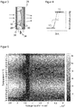
- Figure 5 shows the result of such measurements for a fixed value of V2, the numerical value for V2 being 34 V purely by way of example.
- the varied voltage V1 is plotted on the X-axis, the varied temperature on the Y-axis, the scale not being ordered here, but corresponding to the series of measurements of the temperatures actually set for the measurement.
- the corresponding Figure 4 measured focusing time is color or gray value coded.
- the entire function F (V1 V2, T) would have a further dimension with varying V2 and would not be representable, but can certainly be determined and im Memory of the sensor 10 are stored.
- the focus time increases accordingly Figure 5 with the temperature. At 6 ° C it is still a maximum of 60 ms, at 65 ° degrees only 20 ms.
- V1 and V2 approach each other, the focusing time becomes very short with ⁇ 5 ms.
- the voltage V1 at which the Response time is minimized is close to the focusing voltage V2, but has slight temperature dependencies. The latter could be an artifact of the partially indirect determination of the voltages and temperatures in the acquisition of the data for Figure 5 be.
- the function F (V1, V2, T) obtained in this way can now be used for a passive system without temperature regulation. After the focusing time has expired, it is ensured that the inertia of the liquid lens 26 is overcome and the desired focus position is set. F (V1, V2, T) ensures that there is no unnecessarily long wait for it, but rather that the sensor 10 is available again as quickly as possible after each individual refocusing.
- the function F ( ⁇ V, T) can of course also be obtained from F (V1, V2, T) by simplification.
Landscapes
- Physics & Mathematics (AREA)
- General Physics & Mathematics (AREA)
- Optics & Photonics (AREA)
- Engineering & Computer Science (AREA)
- Multimedia (AREA)
- Signal Processing (AREA)
- Automatic Focus Adjustment (AREA)
- Studio Devices (AREA)
Applications Claiming Priority (1)
| Application Number | Priority Date | Filing Date | Title |
|---|---|---|---|
| DE102018132015.9A DE102018132015B4 (de) | 2018-12-13 | 2018-12-13 | Optoelektronischer Sensor und Verfahren zum Fokussieren |
Publications (1)
| Publication Number | Publication Date |
|---|---|
| EP3668082A1 true EP3668082A1 (fr) | 2020-06-17 |
Family
ID=68731663
Family Applications (1)
| Application Number | Title | Priority Date | Filing Date |
|---|---|---|---|
| EP19210046.9A Ceased EP3668082A1 (fr) | 2018-12-13 | 2019-11-19 | Capteur optoélectronique et procédé de mise au point |
Country Status (4)
| Country | Link |
|---|---|
| US (1) | US20200192006A1 (fr) |
| EP (1) | EP3668082A1 (fr) |
| CN (1) | CN111327815A (fr) |
| DE (1) | DE102018132015B4 (fr) |
Cited By (2)
| Publication number | Priority date | Publication date | Assignee | Title |
|---|---|---|---|---|
| DE102021119680A1 (de) | 2021-07-29 | 2023-02-02 | Sick Ag | Optoelektronische sensoranordnung |
| EP4184224A1 (fr) * | 2021-11-22 | 2023-05-24 | Hexagon Technology Center GmbH | Compensation de température pour lentille liquide |
Families Citing this family (6)
| Publication number | Priority date | Publication date | Assignee | Title |
|---|---|---|---|---|
| DE102020122410B3 (de) * | 2020-08-27 | 2021-11-04 | Trumpf Laser- Und Systemtechnik Gmbh | Fokussiervorrichtung und Verfahren zum Fokussieren einer Objektivlinse |
| EP4105682B1 (fr) * | 2021-06-18 | 2023-08-02 | Sick Ag | Capteur optoélectronique et procédé de détection des objets |
| CN115793172B (zh) * | 2022-12-16 | 2026-03-17 | 太原理工大学 | 一种具有长焦距的热学透镜 |
| CN116320709A (zh) * | 2023-03-22 | 2023-06-23 | 维沃移动通信有限公司 | 摄像组件、测距方法、测距装置、电子设备及介质 |
| US20250291152A1 (en) * | 2024-03-15 | 2025-09-18 | Zebra Technologies Corporation | Method for Tuning an Imaging Assembly via a Focus Triggering Marker |
| CN119291818B (zh) * | 2024-10-11 | 2025-09-23 | 广州大学 | 光控色素微流透镜及其动态形状调整系统及方法 |
Citations (7)
| Publication number | Priority date | Publication date | Assignee | Title |
|---|---|---|---|---|
| WO2006051437A1 (fr) | 2004-11-10 | 2006-05-18 | Koninklijke Philips Electronics N.V. | Appareil electronique muni d'un dispositif optique a base de liquide, et procede de commande de l'appareil |
| US20070279365A1 (en) * | 2006-05-31 | 2007-12-06 | Citizen Holdings Co., Ltd. | Automatic focusing apparatus |
| US20100259833A1 (en) * | 2009-04-10 | 2010-10-14 | Blackeye Optics, Llc. | Variable power optical system |
| US20110200314A1 (en) | 2008-08-12 | 2011-08-18 | Optoelectronics Co. Ltd. | Liquid lens with temperature compensated focus time |
| EP2924974A1 (fr) | 2014-03-24 | 2015-09-30 | Sick Ag | Dispositif opto-électronique et procédé pour capturer des images nettes |
| US9575221B2 (en) | 2013-12-31 | 2017-02-21 | Cognex Corporation | Systems and methods reduce temperature induced drift effects on a liquid lens |
| DE102017119517A1 (de) * | 2016-08-30 | 2018-03-01 | Cognex Corporation | Systeme und Verfahren zur Reduzierung temperaturbedingter Drifteffekte bei einer Flüssiglinse |
Family Cites Families (2)
| Publication number | Priority date | Publication date | Assignee | Title |
|---|---|---|---|---|
| CN204065445U (zh) * | 2014-07-22 | 2014-12-31 | 联想(北京)有限公司 | 镜头模组和摄像头模组 |
| CN106226975B (zh) * | 2016-07-20 | 2019-03-19 | 成都微晶景泰科技有限公司 | 自动对焦方法、设备及成像装置 |
-
2018
- 2018-12-13 DE DE102018132015.9A patent/DE102018132015B4/de active Active
-
2019
- 2019-11-19 EP EP19210046.9A patent/EP3668082A1/fr not_active Ceased
- 2019-12-04 CN CN201911224974.7A patent/CN111327815A/zh active Pending
- 2019-12-12 US US16/712,389 patent/US20200192006A1/en not_active Abandoned
Patent Citations (7)
| Publication number | Priority date | Publication date | Assignee | Title |
|---|---|---|---|---|
| WO2006051437A1 (fr) | 2004-11-10 | 2006-05-18 | Koninklijke Philips Electronics N.V. | Appareil electronique muni d'un dispositif optique a base de liquide, et procede de commande de l'appareil |
| US20070279365A1 (en) * | 2006-05-31 | 2007-12-06 | Citizen Holdings Co., Ltd. | Automatic focusing apparatus |
| US20110200314A1 (en) | 2008-08-12 | 2011-08-18 | Optoelectronics Co. Ltd. | Liquid lens with temperature compensated focus time |
| US20100259833A1 (en) * | 2009-04-10 | 2010-10-14 | Blackeye Optics, Llc. | Variable power optical system |
| US9575221B2 (en) | 2013-12-31 | 2017-02-21 | Cognex Corporation | Systems and methods reduce temperature induced drift effects on a liquid lens |
| EP2924974A1 (fr) | 2014-03-24 | 2015-09-30 | Sick Ag | Dispositif opto-électronique et procédé pour capturer des images nettes |
| DE102017119517A1 (de) * | 2016-08-30 | 2018-03-01 | Cognex Corporation | Systeme und Verfahren zur Reduzierung temperaturbedingter Drifteffekte bei einer Flüssiglinse |
Cited By (3)
| Publication number | Priority date | Publication date | Assignee | Title |
|---|---|---|---|---|
| DE102021119680A1 (de) | 2021-07-29 | 2023-02-02 | Sick Ag | Optoelektronische sensoranordnung |
| EP4184224A1 (fr) * | 2021-11-22 | 2023-05-24 | Hexagon Technology Center GmbH | Compensation de température pour lentille liquide |
| US12578512B2 (en) | 2021-11-22 | 2026-03-17 | Hexagon Technology Center Gmbh | Temperature compensation for liquid lens |
Also Published As
| Publication number | Publication date |
|---|---|
| US20200192006A1 (en) | 2020-06-18 |
| DE102018132015A1 (de) | 2020-06-18 |
| CN111327815A (zh) | 2020-06-23 |
| DE102018132015B4 (de) | 2024-11-14 |
Similar Documents
| Publication | Publication Date | Title |
|---|---|---|
| DE102018132015B4 (de) | Optoelektronischer Sensor und Verfahren zum Fokussieren | |
| EP2924974B1 (fr) | Dispositif opto-électronique et procédé pour capturer des images nettes | |
| DE102014114931B4 (de) | System zum Verringern von temperaturbedingten Drifterscheinungen auf einer Flüssiglinse | |
| DE102014104028B4 (de) | Optoelektronische Vorrichtung und Verfahren zum Justieren | |
| EP2924477B1 (fr) | Dispositif optoélectronique et procédé de détection d'informations d'objets | |
| DE102017119517B4 (de) | Systeme und Verfahren zur Reduzierung temperaturbedingter Drifteffekte bei einer Flüssiglinse | |
| EP3338131B1 (fr) | Dispositif de reproduction à multiples ouvertures avec possibilité de réglage individuel des canaux | |
| EP2701380B1 (fr) | Caméra et procédé pour la prise des images nettes | |
| DE602004008360T2 (de) | Digitale Kamera mit entfernungsabhängigem Fokussierungsverfahren | |
| DE102020109929B3 (de) | Erfassung von Bilddaten eines bewegten Objekts | |
| DE112021001751T5 (de) | Intelligentes verfahren zur verfolgung eines fokus in maschinellen sichtanwendungen | |
| DE69128437T2 (de) | Apparat zur Kontrolle eines optischen Systems | |
| EP2112540A1 (fr) | Dispositif d'identification pour l'acquisition linéaire d'un code dans un plan d'objet | |
| DE102014114471B4 (de) | Mikroskop mit sich automatisch anpassender Irisblende | |
| DE202018107124U1 (de) | Optoelektronischer Sensor | |
| WO2014147257A1 (fr) | Procédé par microscopie optique de localisation d'objets ponctuels | |
| DE112004000126T5 (de) | Mikroskopvorrichtung | |
| EP2823254B1 (fr) | Procédé de détermination de la distance entre une caméra et un objet et système permettant la mise en uvre dudit procédé | |
| EP3974878B1 (fr) | Module de lentille | |
| DE19502045A1 (de) | Kompensation von Bildverwaschungen | |
| DE102023100922A1 (de) | OIS-System und Verfahren zur Steuerung des OIS-Systems | |
| EP2187242B2 (fr) | Capteur optoélectronique et méthode pour la mise au point du premier | |
| DE102012002853A1 (de) | Fokussiervorrichtung | |
| DE102019132003A1 (de) | Optische Einheit und Verfahren zum Betreiben einer optischen Einheit | |
| DE102018215601A1 (de) | Anordnung von Mikrospiegeln, Mikrospiegelvorrichtung, Verwendung einer Mikro-spiegelvorrichtung, Abbildungssystem, Verfahren und Computerprogrammprodukt zur Aufweitung eines Schärfebereichs des Abbildungssystems und/oder zur Erzeugung eines Tiefenbildes |
Legal Events
| Date | Code | Title | Description |
|---|---|---|---|
| PUAI | Public reference made under article 153(3) epc to a published international application that has entered the european phase |
Free format text: ORIGINAL CODE: 0009012 |
|
| 17P | Request for examination filed |
Effective date: 20200430 |
|
| AK | Designated contracting states |
Kind code of ref document: A1 Designated state(s): AL AT BE BG CH CY CZ DE DK EE ES FI FR GB GR HR HU IE IS IT LI LT LU LV MC MK MT NL NO PL PT RO RS SE SI SK SM TR |
|
| AX | Request for extension of the european patent |
Extension state: BA ME |
|
| 17Q | First examination report despatched |
Effective date: 20200602 |
|
| 18R | Application refused |
Effective date: 20201024 |