EP3668096A1 - Verfahren und vorrichtung zur codierung einer sequenz von bildern unter verwendung eines ersten und eines zweiten codierers - Google Patents
Verfahren und vorrichtung zur codierung einer sequenz von bildern unter verwendung eines ersten und eines zweiten codierers Download PDFInfo
- Publication number
- EP3668096A1 EP3668096A1 EP18211477.7A EP18211477A EP3668096A1 EP 3668096 A1 EP3668096 A1 EP 3668096A1 EP 18211477 A EP18211477 A EP 18211477A EP 3668096 A1 EP3668096 A1 EP 3668096A1
- Authority
- EP
- European Patent Office
- Prior art keywords
- image
- motion
- image data
- sequence
- encoded
- Prior art date
- Legal status (The legal status is an assumption and is not a legal conclusion. Google has not performed a legal analysis and makes no representation as to the accuracy of the status listed.)
- Granted
Links
Images


Classifications
-
- H—ELECTRICITY
- H04—ELECTRIC COMMUNICATION TECHNIQUE
- H04N—PICTORIAL COMMUNICATION, e.g. TELEVISION
- H04N19/00—Methods or arrangements for coding, decoding, compressing or decompressing digital video signals
- H04N19/50—Methods or arrangements for coding, decoding, compressing or decompressing digital video signals using predictive coding
- H04N19/503—Methods or arrangements for coding, decoding, compressing or decompressing digital video signals using predictive coding involving temporal prediction
- H04N19/51—Motion estimation or motion compensation
- H04N19/513—Processing of motion vectors
- H04N19/517—Processing of motion vectors by encoding
-
- H—ELECTRICITY
- H04—ELECTRIC COMMUNICATION TECHNIQUE
- H04N—PICTORIAL COMMUNICATION, e.g. TELEVISION
- H04N19/00—Methods or arrangements for coding, decoding, compressing or decompressing digital video signals
- H04N19/10—Methods or arrangements for coding, decoding, compressing or decompressing digital video signals using adaptive coding
- H04N19/134—Methods or arrangements for coding, decoding, compressing or decompressing digital video signals using adaptive coding characterised by the element, parameter or criterion affecting or controlling the adaptive coding
- H04N19/167—Position within a video image, e.g. region of interest [ROI]
-
- H—ELECTRICITY
- H04—ELECTRIC COMMUNICATION TECHNIQUE
- H04N—PICTORIAL COMMUNICATION, e.g. TELEVISION
- H04N19/00—Methods or arrangements for coding, decoding, compressing or decompressing digital video signals
- H04N19/10—Methods or arrangements for coding, decoding, compressing or decompressing digital video signals using adaptive coding
- H04N19/102—Methods or arrangements for coding, decoding, compressing or decompressing digital video signals using adaptive coding characterised by the element, parameter or selection affected or controlled by the adaptive coding
- H04N19/124—Quantisation
-
- H—ELECTRICITY
- H04—ELECTRIC COMMUNICATION TECHNIQUE
- H04N—PICTORIAL COMMUNICATION, e.g. TELEVISION
- H04N19/00—Methods or arrangements for coding, decoding, compressing or decompressing digital video signals
- H04N19/10—Methods or arrangements for coding, decoding, compressing or decompressing digital video signals using adaptive coding
- H04N19/102—Methods or arrangements for coding, decoding, compressing or decompressing digital video signals using adaptive coding characterised by the element, parameter or selection affected or controlled by the adaptive coding
- H04N19/119—Adaptive subdivision aspects, e.g. subdivision of a picture into rectangular or non-rectangular coding blocks
-
- H—ELECTRICITY
- H04—ELECTRIC COMMUNICATION TECHNIQUE
- H04N—PICTORIAL COMMUNICATION, e.g. TELEVISION
- H04N19/00—Methods or arrangements for coding, decoding, compressing or decompressing digital video signals
- H04N19/10—Methods or arrangements for coding, decoding, compressing or decompressing digital video signals using adaptive coding
- H04N19/102—Methods or arrangements for coding, decoding, compressing or decompressing digital video signals using adaptive coding characterised by the element, parameter or selection affected or controlled by the adaptive coding
- H04N19/127—Prioritisation of hardware or computational resources
-
- H—ELECTRICITY
- H04—ELECTRIC COMMUNICATION TECHNIQUE
- H04N—PICTORIAL COMMUNICATION, e.g. TELEVISION
- H04N19/00—Methods or arrangements for coding, decoding, compressing or decompressing digital video signals
- H04N19/10—Methods or arrangements for coding, decoding, compressing or decompressing digital video signals using adaptive coding
- H04N19/134—Methods or arrangements for coding, decoding, compressing or decompressing digital video signals using adaptive coding characterised by the element, parameter or criterion affecting or controlling the adaptive coding
- H04N19/136—Incoming video signal characteristics or properties
- H04N19/137—Motion inside a coding unit, e.g. average field, frame or block difference
- H04N19/139—Analysis of motion vectors, e.g. their magnitude, direction, variance or reliability
-
- H—ELECTRICITY
- H04—ELECTRIC COMMUNICATION TECHNIQUE
- H04N—PICTORIAL COMMUNICATION, e.g. TELEVISION
- H04N19/00—Methods or arrangements for coding, decoding, compressing or decompressing digital video signals
- H04N19/10—Methods or arrangements for coding, decoding, compressing or decompressing digital video signals using adaptive coding
- H04N19/134—Methods or arrangements for coding, decoding, compressing or decompressing digital video signals using adaptive coding characterised by the element, parameter or criterion affecting or controlling the adaptive coding
- H04N19/157—Assigned coding mode, i.e. the coding mode being predefined or preselected to be further used for selection of another element or parameter
- H04N19/159—Prediction type, e.g. intra-frame, inter-frame or bidirectional frame prediction
-
- H—ELECTRICITY
- H04—ELECTRIC COMMUNICATION TECHNIQUE
- H04N—PICTORIAL COMMUNICATION, e.g. TELEVISION
- H04N19/00—Methods or arrangements for coding, decoding, compressing or decompressing digital video signals
- H04N19/10—Methods or arrangements for coding, decoding, compressing or decompressing digital video signals using adaptive coding
- H04N19/169—Methods or arrangements for coding, decoding, compressing or decompressing digital video signals using adaptive coding characterised by the coding unit, i.e. the structural portion or semantic portion of the video signal being the object or the subject of the adaptive coding
- H04N19/17—Methods or arrangements for coding, decoding, compressing or decompressing digital video signals using adaptive coding characterised by the coding unit, i.e. the structural portion or semantic portion of the video signal being the object or the subject of the adaptive coding the unit being an image region, e.g. an object
- H04N19/172—Methods or arrangements for coding, decoding, compressing or decompressing digital video signals using adaptive coding characterised by the coding unit, i.e. the structural portion or semantic portion of the video signal being the object or the subject of the adaptive coding the unit being an image region, e.g. an object the region being a picture, frame or field
-
- H—ELECTRICITY
- H04—ELECTRIC COMMUNICATION TECHNIQUE
- H04N—PICTORIAL COMMUNICATION, e.g. TELEVISION
- H04N19/00—Methods or arrangements for coding, decoding, compressing or decompressing digital video signals
- H04N19/10—Methods or arrangements for coding, decoding, compressing or decompressing digital video signals using adaptive coding
- H04N19/169—Methods or arrangements for coding, decoding, compressing or decompressing digital video signals using adaptive coding characterised by the coding unit, i.e. the structural portion or semantic portion of the video signal being the object or the subject of the adaptive coding
- H04N19/17—Methods or arrangements for coding, decoding, compressing or decompressing digital video signals using adaptive coding characterised by the coding unit, i.e. the structural portion or semantic portion of the video signal being the object or the subject of the adaptive coding the unit being an image region, e.g. an object
- H04N19/174—Methods or arrangements for coding, decoding, compressing or decompressing digital video signals using adaptive coding characterised by the coding unit, i.e. the structural portion or semantic portion of the video signal being the object or the subject of the adaptive coding the unit being an image region, e.g. an object the region being a slice, e.g. a line of blocks or a group of blocks
-
- H—ELECTRICITY
- H04—ELECTRIC COMMUNICATION TECHNIQUE
- H04N—PICTORIAL COMMUNICATION, e.g. TELEVISION
- H04N19/00—Methods or arrangements for coding, decoding, compressing or decompressing digital video signals
- H04N19/10—Methods or arrangements for coding, decoding, compressing or decompressing digital video signals using adaptive coding
- H04N19/169—Methods or arrangements for coding, decoding, compressing or decompressing digital video signals using adaptive coding characterised by the coding unit, i.e. the structural portion or semantic portion of the video signal being the object or the subject of the adaptive coding
- H04N19/17—Methods or arrangements for coding, decoding, compressing or decompressing digital video signals using adaptive coding characterised by the coding unit, i.e. the structural portion or semantic portion of the video signal being the object or the subject of the adaptive coding the unit being an image region, e.g. an object
- H04N19/176—Methods or arrangements for coding, decoding, compressing or decompressing digital video signals using adaptive coding characterised by the coding unit, i.e. the structural portion or semantic portion of the video signal being the object or the subject of the adaptive coding the unit being an image region, e.g. an object the region being a block, e.g. a macroblock
-
- H—ELECTRICITY
- H04—ELECTRIC COMMUNICATION TECHNIQUE
- H04N—PICTORIAL COMMUNICATION, e.g. TELEVISION
- H04N19/00—Methods or arrangements for coding, decoding, compressing or decompressing digital video signals
- H04N19/10—Methods or arrangements for coding, decoding, compressing or decompressing digital video signals using adaptive coding
- H04N19/169—Methods or arrangements for coding, decoding, compressing or decompressing digital video signals using adaptive coding characterised by the coding unit, i.e. the structural portion or semantic portion of the video signal being the object or the subject of the adaptive coding
- H04N19/177—Methods or arrangements for coding, decoding, compressing or decompressing digital video signals using adaptive coding characterised by the coding unit, i.e. the structural portion or semantic portion of the video signal being the object or the subject of the adaptive coding the unit being a group of pictures [GOP]
-
- H—ELECTRICITY
- H04—ELECTRIC COMMUNICATION TECHNIQUE
- H04N—PICTORIAL COMMUNICATION, e.g. TELEVISION
- H04N19/00—Methods or arrangements for coding, decoding, compressing or decompressing digital video signals
- H04N19/42—Methods or arrangements for coding, decoding, compressing or decompressing digital video signals characterised by implementation details or hardware specially adapted for video compression or decompression, e.g. dedicated software implementation
- H04N19/43—Hardware specially adapted for motion estimation or compensation
-
- H—ELECTRICITY
- H04—ELECTRIC COMMUNICATION TECHNIQUE
- H04N—PICTORIAL COMMUNICATION, e.g. TELEVISION
- H04N19/00—Methods or arrangements for coding, decoding, compressing or decompressing digital video signals
- H04N19/42—Methods or arrangements for coding, decoding, compressing or decompressing digital video signals characterised by implementation details or hardware specially adapted for video compression or decompression, e.g. dedicated software implementation
- H04N19/436—Methods or arrangements for coding, decoding, compressing or decompressing digital video signals characterised by implementation details or hardware specially adapted for video compression or decompression, e.g. dedicated software implementation using parallelised computational arrangements
-
- H—ELECTRICITY
- H04—ELECTRIC COMMUNICATION TECHNIQUE
- H04N—PICTORIAL COMMUNICATION, e.g. TELEVISION
- H04N19/00—Methods or arrangements for coding, decoding, compressing or decompressing digital video signals
- H04N19/44—Decoders specially adapted therefor, e.g. video decoders which are asymmetric with respect to the encoder
-
- H—ELECTRICITY
- H04—ELECTRIC COMMUNICATION TECHNIQUE
- H04N—PICTORIAL COMMUNICATION, e.g. TELEVISION
- H04N19/00—Methods or arrangements for coding, decoding, compressing or decompressing digital video signals
- H04N19/70—Methods or arrangements for coding, decoding, compressing or decompressing digital video signals characterised by syntax aspects related to video coding, e.g. related to compression standards
Definitions
- the present invention relates to the field of image encoding.
- it relates to a method and device for encoding a plurality of image frames using two separate encoders, where each image frame is divided into two portions to each be encoded by one of the two encoders.
- the number of monitoring cameras e.g., network camera monitoring systems
- the possible image resolution of an image captured by an image sensor of a monitoring camera has increased. This is advantageous from a monitoring perspective, since more details in the monitored scene may be captured.
- this development has resulted in that an image captured by a high-resolution image sensor may be too large for one encoder (encoder chip) to encode at an acceptable frame rate.
- the concept of tiles/slices in, e.g. H.265 encoding may be employed to produce a single encoded image from image data encoded by a plurality of encoders, such as two encoders.
- image data of an image frame can be divided into at least a first and a second portion of image data, where the first portion is encoded by a first encoder, and the second portion is encoded by a second encoder, wherein the two encoders have separate buffer memories (reference buffers) for reference encoding.
- motion vector search is not performed in the entire reference frame, though, but in a limited search window, in order for the search to be finished in a short enough time to maintain a desired frame rate. Therefore, it will not be necessary to copy the whole reference frame slice or tile from one encoder to the other, but only a sufficiently large portion to accommodate the search window.
- the search window for the motion vector search may be restricted.
- the encoders may be restricted to not search for motion vectors in reference frames produced by the other encoder. This may be achieved in a system that allows for using different search windows for different parts of the image by setting the motion search window at the boundary between the portions of the image data such that motion search will not be performed over the boundary.
- a drawback of that approach is that it may be costlier (require more bitrate) to encode image data near the boundary, due to motion in the image data between image frames.
- the motion prediction using a block matching algorithm
- image content may move from the image data encoded by the first encoder in a first image frame to the image data encoded by the second encoder for a subsequent image frame.
- This may result in that these block of pixels will be encoded I-blocks, or encoded as P-blocks with much residual data to be encoded, thus increasing the bit rate.
- the above object is achieved by a method for encoding a sequence of image frames using a first and a second encoder which operate independently of each other, the method comprising:
- first and second encoder which operate independently of each other generally means that no transfer of data is necessary between the first and second encoder for encoding purposes.
- each of the first and the second encoder only refers to reference frames produced by itself when performing inter-coding.
- image data which has been encoded by the first encoder will be stored (in a decoded version) in the reference buffer of the first encoder and used for inter-coding purposes (as reference data for block matching of the first portion of image data of a particular image frame).
- image data which has been encoded by the second encoder will be stored (in a decoded version) in the reference buffer of the second encoder and used for inter-coding purposes (as reference data for block matching of the second portion of image data of a particular image frame).
- the dividing of the image data results in (at least) two coherent portions of image data wherein the first portion of image data may represent a first tile or slice and wherein the second portion of image data may represent a second tile or slice. Consequently, the boundary may be both straight or stepped.
- some of the macroblocks may be part of the first portion of image data, and the remaining macroblocks may be part of the second portion of image data.
- the inventors have realized that by estimating motion in the sequence of image frames, the image data of each image frame can be divided into at least a first and a second portion to minimize the (estimated) motion across the boundary between the first and second portion.
- the bitrate may not be substantially increased because of the use of separate encoder with separate buffer memories, where no copying of reference data is performed between the two encoders. Since dividing the image data according to the above is done, the motion prediction will generally work better for more block of pixels (macroblocks, coding units [CU], coding tree units [CTU]), even though no data is copied between the first and second encoder. In other words, by positioning the boundary according to the above, the problem of high bit rate cost for additional I-blocks, or P-blocks with a high cost for encoding the residual, may be reduced.
- first and second encoders which operate independently of each other are that the synchronization requirement between the two encoders is reduced or removed. Since no data is required to be copied between the first and second encoder, the encoders can encode their respective portions of image data for a plurality of image frames without having to wait for the other encoder to complete encoding of e.g. data to be used for inter-encoding purposes.
- the motion in the sequence of image frames may be estimated in many different ways.
- a separate motion estimator may analyze previous image frames (e.g. image frames corresponding to a time span of a second, three seconds, etc., of a captured video sequence), to estimate motion in the sequence of image frames. Such estimation may be performed on a down sampled version of the image frames for reducing computational complexity.
- motion vectors of previously encoded image frames are analyzed to estimate the motion in the sequence of image frames.
- pan-tilt motion of a video capturing device capturing the sequence of image frames may be analyzed to determine the estimated motion.
- the estimated motion may be used to determine a predominant direction of motion in the image frames, i.e. determine if the motion is generally horizontal or vertical in the sequence of image frames. In other embodiments, the estimated motion may be used to determine positions in the image frames where motion is present, for example if motion is mostly present in the upper corner of image frames of the sequence the image frames, or in a section in the middle of image frames of the sequence of image frames, etc.,.
- the boundary between the first and the second portion is positioned in a same location and direction for a plurality of image frames of the sequence.
- the computational complexity of the method is reduced.
- the first and second portions occupy the same spatial region over all of the plurality of image frames.
- the encoders thus restrict motion estimation to the same spatial area in the previous frame (reference frame).
- both the first and the second encoder restricts its search window for block matching of a block of pixels in the first portion and the second portion of image data, respectively, to a reference frame produced by itself.
- the plurality of image frames of the sequence forms a first group of pictures, GOP.
- the motion estimation may thus be done for only the first image frame of the GOP, which will reduce the computational complexity of the encoding method, and the dividing of image data determined for the first image frame may be similarly performed for the rest of image frames of the GOP.
- the boundary between the first and the second portion is positioned in a first position and direction for the first GOP and in a second position and direction for a second GOP.
- a sequence of image frames capturing a dynamic scene (or captured by a camera which moves, pan-tilt, differently between the first and second GOP, etc.,) may be efficiently encoded.
- the direction of the boundary is kept between the first and second GOP, but the position is adjusted, e.g. to divide the computational burden of encoding between the first and second encoder in a different way, or in view of a new privacy mask (see further below), etc.,.
- the direction of the boundary is horizontal.
- the direction of the boundary is vertical.
- a low complexity method may be achieved. For example, if there is a lot of vertical motion in the image, the image is divided vertically (tiling) and the left and the right part are encoded separately in different encoders. If there is a lot of horizontal motion in the image, the image is divided horizontally (slicing), and the top and the bottom part of the image are encoded separately in different encoders.
- the dividing of image data of each image frame of the sequence into at least a first and a second portion of image data further is based on a map of quantization parameters used when encoding the sequence of image frames, the map of quantization parameters specifying quantization parameters used when compressing different regions of image data of the image frames of the sequence, wherein the quantization parameters are weighted in to favor positioning the boundary in a region of image data encoded with a higher quantization parameter over a region of image data encoded with a lower quantization parameter.
- the bitrate may be further reduced, since by placing boundary between the first and second portions in an image region which often have a relatively higher quantization parameter (e.g. QP value), even if motion exist in this image region, the resulting intra encoded block of pixels will be more compressed due to the higher quantization parameter.
- a relatively higher quantization parameter e.g. QP value
- the dividing of image data of each image frame of the sequence into at least a first and a second portion of image data further is based on at least one privacy mask applied to the sequence of image frames, wherein a position and size of each of the at least one privacy masks is weighted in to favor positioning the boundary in a region of image data corresponding to a privacy mask over a region of image data not corresponding to a privacy mask.
- the bitrate may be further reduced, since by placing the boundary between the first and second portions in an image region part of a privacy mask zone, even if motion over the boundary exist in this image region, the block of pixels in the privacy mask zone will anyway be e.g. encoded as a single color block of pixels and thus not require much bitrate.
- the step of estimating motion comprises receiving data indicative of a pan-tilt, PT, motion of a video capturing device capturing the sequence of image frames, wherein upon the received data indicating a panning motion, the direction of the boundary is horizontal; wherein upon the received data indicating a tilting motion, the direction of the boundary is vertical.
- This embodiment represents a low complexity functionality of determining a predominant direction of motion in the image frames.
- image data of an image frame in the sequence is divided into at least a first and a second portion of image data based on motion which is estimated from previous image frames in the sequence. This allows for parallel processing of the task of estimating the motion and the task of encoding of the image frames.
- the step of estimating motion comprises receiving data indicating motion present in the previous image frames in the sequence, and using the received data for estimating motion from the previous image frames.
- the data indicating motion may be determined by a motion estimating unit separate from the two encoders, advantageously allowing for dividing tasks of the encoding method described herein between different units to further improve efficiency of the method.
- the received data may take any suitable form, from a very simple data (e.g. a Boolean value describing if the predominant direction of motion in the image frames is vertical or horizontal) to more complex data (e.g. a map of values or motion vectors describing motion in separate parts of the image frames).
- the step of estimating motion comprises analyzing motion vectors calculated by the first and the second encoder when encoding the first and the second portions, respectively, of the previous image frames.
- data already produced by the encoders may be used for estimating motion. For example, an absolute value of the x-values of all motion vectors may be averaged to estimate motion in a horizontal direction, and compare this with an average of the absolute values of the y-values of all motion vectors, to determine a predominant direction of motion in the image frames.
- the method further comprises the steps of: for each image frame in the sequence, receiving, by a stream multiplexer, the first portion of image data encoded by the first encoder and the second portion of image data encoded by the second encoder, and forming an encoded image, the encoded image comprising the encoded first portion of image data as a first tile or a first slice and the encoded second portion of image data as a second tile or a second slice.
- the data encoded by the separate encoders are multiplexed into a single encoded stream.
- the encoded data from the first encoder, and the encoded data from the second encoder is sent to a separate stream multiplexer for forming (multiplexing) an encoded image stream.
- one of the two encoders are functioning as the stream multiplexer.
- a computer program product comprising a computer-readable medium with computer code instructions adapted to carry out the method of the first aspect when executed by a device having processing capability.
- a device for encoding a sequence of image frames comprising:
- the device further comprises a stream multiplexer; wherein the stream multiplexer is arranged to receive the first portion of image data encoded by the first encoder and the second portion of image data encoded by the second encoder, and to form an encoded image, the encoded image comprising the encoded first portion of image data as a first tile or a first slice and the encoded second portion of image data as a second tile or a second slice.
- the stream multiplexer is arranged to receive the first portion of image data encoded by the first encoder and the second portion of image data encoded by the second encoder, and to form an encoded image, the encoded image comprising the encoded first portion of image data as a first tile or a first slice and the encoded second portion of image data as a second tile or a second slice.
- the second and third aspects may generally have the same features and advantages as the first aspect. It is further noted that the invention relates to all possible combinations of features unless explicitly stated otherwise.
- AVC Advanced Video Coding
- HEVC High Efficiency Video Coding
- Tiles and slices allow for the image to be divided into a grid of rectangular (or substantially rectangular, as will be described below in conjunction with figure 4 ) regions that can be decoded/encoded in parallel. In other words, this concept may be used for parallel processing purposes, to let separate encoders or cores of an encoder encode an image frame in parallel.
- separate encoders (a first and second encoder), having separate buffer memory for reference encoding (inter encoding, P-frame encoding, B-frame encoding), are employed, using the concept of tiles/slices to encode an image frame.
- inter encoding, P-frame encoding, B-frame encoding inter encoding, P-frame encoding, B-frame encoding
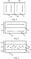
- Figure 1 shows by way of example a way of dividing image data of an image frame 102 into a first 104 and second 106 portion.
- motion 110 represented in figures 1-5 by arrows
- a position of the boundary 108 is in this case chosen to achieve equal size of the first 104 and second 106 portion of image data.
- This will advantageously result in similar computational burden for the two encoders that will independently encode the two portions 104, 106.
- the boundary 108 may be placed differently to better take advantage of available computational resources.
- a scene 800 comprising two vertically moving objects 802, 804 are shown.
- the scene 800 is captured by a video camera 700, which produces a sequence of image frames 102 comprising a first 102a and second 102b image frame.
- the motion of the image frames 102 are estimated (as will be further described below), and the estimation results in that a predominant direction of motion in the image frames 102a-b is determined to be vertical.
- image data of the image frames 102a-b in the sequence is divided into at least a first 104 a-b and a second (not shown in figure 8 ) portion of image data.
- the first portions 104a-b are sent to a first encoder 706 for encoding.
- the second portions are sent to a second encoder for encoding, but this is omitted from figure 8 for ease of description.
- the encoder 706 For a first 104a of the first portions 104a-b (i.e. image data of the first image frame 102a), the encoder 706 in this case performs intra-encoding into encoded data 714a.
- the encoder For a second 104b of the first portions 104a-b (i.e. image data of the second image frame 102b), the encoder in this case performs inter encoding. Since the first and second encoders operate independently of each other as defined above, the first encoder 706 only has data corresponding to (i.e.
- the block matching 806 of image data corresponding to (depicting) the first object 802 of the captured scene 802 will find similar image data between the portions of image data encoded by the first encoder 706 as illustrated in figure 8 by the dashed squares. Bitrate may thus be kept low. Compare this to dividing the image data of the image frames 102a-b in a horizontal direction, where block matching for the image data corresponding to (depicting) the first object 802 of the captured scene 802 would fail, resulting in an increased bit rate.
- the boundary between the first and the second portion is positioned in a same location and direction for a plurality of image frames 102a, 102b of the sequence.
- the plurality of image frames of the sequence forms a GOP, which means that image data is divided in a same way for all image frames of the GOP.
- a new motion estimation may be performed, resulting in that the boundary between the first and the second portion of image data is positioned in a first position and direction for the first GOP and in a second position and direction for a second GOP.
- the step of motion estimation is performed less frequent, for example based on a time of day, such that motion estimation is e.g. performed less frequent during night time compared to during day time.
- the boundary between the first and the second portion is positioned in a same location and direction for a plurality of GOPs.
- Figures 2-6 shows other ways of dividing image data of an image frame 102 based on estimated motion in the image frame.
- the above description of figure 2 and 8 applies to the embodiments of figure 2-6 , mutatis mutandis.
- Figure 2 shows by way of example another way of dividing image data of an image frame 102 into a first 104 and second 106 part.
- Figure 2 is similar to figure 1 .
- motion 110 in the image data of the image frame 102 have been estimated to have a predominant direction which is horizontal, which means that also a direction of a boundary 108 between the first 104 and the second portion 106 is horizontal.
- Figure 3 shows by way of example another way of dividing image data of an image frame 102.
- motion 110 in the image data of the image frame 102 has been used to estimate positions in the image frame 102 where motion is present.
- motion 110 is (mainly) present in a middle part of the image frame 102.
- the image frame 102 may for example depict a scene with a busy street in the middle (a lot of motion), and houses on both side of the street (little motion). Consequently, the image data of the image frame 102 is divided such that image data 106 containing most of the motion is encoded by one encoder.
- the image data is divided into three portions 104a,104b,106, where one of the encoders encodes the portion 106 with motion, and the other encoder encodes the remaining of the image data, i.e. the upper portion 104a and the lower portion 104b.
- one of the encoders would encode both the portion 106 with the motion, and one of the other portions 104a, 104b, e.g. the lower portion 104b while the other encoder would encode the upper portion 104a.
- the image frame 102 may, in a similar way as described above, be divided into more areas based on the estimated motion. For example, more areas with or without motion may be determined, where the encoding of these areas can be performed by the different encoders to e.g. facilitate similar computational burden for the encoders.
- FIG. 4 the boundaries between the portions of image data encoded by the first and second encoder are shown as straight boundaries. However, it should be noted that a stepped boundary is equally possible, which is shown in figure 4 . H.264 and H.265 support such shaped slices/tiles, and consequently, a portion of image data as described herein is not restricted to a shape of a rectangle.
- CU macroblocks/coding units
- FIG. 4 for a specific row of macroblocks/coding units (CU, CTU) (shown as squares in figure 4 ) in the image data of an image frame 102, some of the macroblocks may be part of the first portion 104 of image data, and the remaining macroblocks may be part of the second portion 106 of image data.
- the macroblocks of the third row are divided between the first portion 104 of image data and the second portion 106 of the image data.
- the dividing of the image data of an image frame may be based on other data than the estimated motion. Since there is a larger risk that macroblocks close to the boundary may require more bits to be encoded compared to macroblocks further from the border, it may be advantageous to place to boundary to mitigate this risk.
- Figures 5 and 6 shows such embodiments.
- Privacy masks to be applied to the sequence of image frames may advantageously be weigh in to further reduce the bit rate.
- Privacy masking is a feature which is used to protect personal privacy by concealing parts of the image frame from view with a masked area. This is shown in figure 5 where a privacy mask 502 is positioned to the right in the image frame 102.
- a privacy mask 502 is positioned to the right in the image frame 102.
- the dividing of image data of each image frame of the sequence into at least a first 104 and a second 106 portion of image data further is based on at least one privacy mask 502 applied to the sequence of image frames, wherein a position and size of each of the at least one privacy masks 502 is weighted in to favor positioning the boundary 108 in a region of image data corresponding to a privacy mask 502 over a region of image data not corresponding to a privacy mask.
- a boundary is positioned based on quntization parameter values.
- the quantization parameters controls the amount of compression for every Macroblock/CU in a frame. Large values mean that there will be higher quantization, more compression, and lower quality. Lower values mean the opposite.
- Figure 6 schamtically shows a map 602 of quantization parameters used when encoding a particular image frame 102. The map 602 is thus specifying quantization parameters used when compressing different regions of image data of the image frames of the sequence.
- the quantization parameters are weighted in to favor positioning the boundary 108 in a region of image data encoded with a higher quantization parameter over a region of image data encoded with a lower quantization parameter.
- Figure 7 schematically shows a video capturing device 700 comprising a device 702 for encoding a sequence of image frames 102.
- the encoding device 702 is thus implemented in the video capturing device 700 but it is equally suitable to implement the encoding device 702 separately from the video capturing device 700, where the encoder device 702 is connected (wireless or wired) to the video capturing device 700 to receive the sequence of image frames 102.
- the video capturing device 700 comprises an image sensor 720 for capturing a sequence of image frames 102 depicting a scene.
- the encoding device 702 is adapted to receive the sequence of image frames 102 captured by the image sensor 720.
- the encoding device 702 comprises a processor 704 configure to estimate S802 motion in the sequence of image frames 102 to determine at least one of: a predominant direction of motion in the image frames, and positions in the image frames where motion is present. Based on the estimated motion, the processor is configured to divide S810 image data of each image frame 102 in the sequence into at least a first 104 and a second 106 portion of image data, wherein a boundary between the first 104 and the second 106 portion is positioned to minimize the estimated motion across the boundary as described above.
- the estimation S802 of motion may be done in many ways and will be exemplified below.
- the step of estimating motion may comprise receiving S808 data 722 indicative of a pan-tilt, PT, motion of the video capturing device 700 capturing the sequence of image frames 102.
- the video capturing device 700 may comprise a sensor 724 for sensing such motion (e.g. a gyro, or a sensor connected to a PT motor of the camera and receiving control signals from e.g. a control unit controlling the PT motor) and to send data 722 indicative of the PT motion to the processor 704.
- the processor 704 may then, upon the received data 722 indicating a panning motion, determining the direction of the boundary to be horizontal. In the case of the received data 722 indicating a tilting motion, the direction of the boundary may be determined to be vertical.
- image data of an image frame 102 in the sequence is divided into at least a first 104 and a second 106 portion of image data based on motion which is estimated from previous image frames in the sequence.
- the processor 704 may be configured to estimate motion using received S804 data 718 indicating motion present in the previous image frames in the sequence, and using the received data for estimating motion from the previous image frames.
- the encoding device 702 is connected to a motion analysing unit 710 which also receives the sequence of image frames 102 and analyse their respective image content for determining the motion present in the image frames 102 using any suitable method.
- the motion analysing unit 710 sends motion vectors calculated for the image frames 102 which it receives (in some embodiments using a down sampled version of them to reduce computational complexity), and send these as data 718 to the processor 704 to be used for estimating S802 motion.
- the step of estimating motion comprises analysing S806 motion vectors calculated by the first and the second encoder when encoding the first and the second portions, respectively, of the previous image frames.
- the length and position of the motion vectors may be used to estimate positions in the image frames where motion is mostly present (e.g. as described in conjunction with figure 3 )
- the motion vectors (e.g. received from the motion analysing unit 710 or from the encodes 706, 708), from one or several from several previous image frames, are averaged to find a predominant direction of motion.
- the average value of the absolute value of each motion vector is calculated, to e.g. determine if the predominant direction of motion is vertical or horizontal.
- motion vectors close to the boundary of a previous image may not accurately estimate motion in the image frame 102, since the motion vectors in this area is restricted from crossing the boundary.
- motion vectors close to the boundary are disregarded when estimating the motion.
- the size of the residuals of the macroblocks near the boundary may be used to determine if the estimated motion in a previous image frame was incorrect.
- the direction of the boundary may be changed from e.g. horizontal to vertical or vice versa.
- a plurality of boundaries may be tested using the motion vectors, to determine, based on how many motion vectors that will extend over respective boundary position and direction, a best position and direction for the boundary such that estimated motion across the boundary is minimized.
- the length of the respective motion vectors is used as a weight, such that a shorter motion vector crossing the boundary is preferred over a longer motion vector.
- the motion vectors are accumulated over time to build a model of the motion over time. For example, for each macroblock/CU, a normal distribution (average value and standard deviation) is held, and updated for each new image frame which becomes part of the model.
- each macroblocks holds a plurality of normal distributions, which each defines different types of motion that may take place in the scene corresponding to the macroblock. For example, if a macroblock represents a road, the motion will be zero if no one is moving on the road, the motion will be fast in one direction when a car passes, and the motion will be slower in another direction when a person crosses the road.
- the model is to be updated with motion in a new image frame, the plurality of normal distributions are considered, and the normal distribution which "fits" to the motion of the new image frame is updated.
- a weight parameter of each normal distribution is updated, the weight parameter defining how often the motion corresponding to a specific normal distribution is happening in the scene (e.g. 40% cars passing, 50% nothing happening and 10% persons crossing the street).
- the weights for the respective normal distributions are used for estimating a motion for the particular macroblock.
- This model may thus be used to determine, by the processor 704, a best position and direction of the boundary, or in other words, to divide S810 image data of each image frame in the sequence into at least a first 104 and a second 106 portion of image data. It should be noted that such a model may be held and updated by either the processor 704 or the motion analysing unit 710. If the model is held by the motion analysing unit 710, the data 718 received S804 by the processor may comprise such model. In other embodiments, the motion analysing unit 710 both hold the model and determine a suitable position for the boundary. In this embodiment, the data 718 received S804 by the processor may comprise one or more suitable positions and direction for a boundary.
- the processor When the motion has been estimated S802, the processor thus, based on the estimated motion, divides S810 image data of image frame(s) 102 in the sequence into at least a first 104 and a second 106 portion of image data, wherein a boundary between the first 104 and the second 106 portion is positioned to minimize the estimated motion across the boundary.
- the boundary may be dynamically updated during the sequence of image frames, e.g. for each image frame, for every n-th image frame, for every GOP etc.,.
- a position of the boundary may optionally also be set S812 based on a map of quantization parameters and/or set S814 based on at least one privacy mask.
- the first portion 104 of image data is sent to a first encoder 706, and the second portion 106 of image data is sent to a second encoder 708.
- the first portion 104 of image data of each image frame 102 in the sequence is thus encoded S816 using the first encoder 706, and the second portion 106 of image data of each image frame 102 in the sequence is thus encoded S818 using the second encoder 708.
- the first 706 and second 708 encoder operate independently of each other, in that no data is transmitted/copied between the encoders for inter encoding purposes.
- the only data used for block matching of a block of pixels of a first portion of an image frame 102 (encoded by the first encoder) is thus (a decoded version of) pixel data of a first portion of an image frame 102 that has already been encoded by the first encoder, and similar for the second encoder.
- the encoders 706, 708 thus each comprise a separate buffer memory (not shown) where image data used for reference encoding (inter encoding, P-frame, B-frame etc.) is stored and continuously replaced.
- the video capturing device 700 further comprises a separate stream multiplexer 712, which for each image frame in the sequence, receives the first portion of image data encoded by the first encoder and the second portion of image data encoded by the second encoder, forms S820 an encoded image 722, the encoded image comprising the encoded first portion of image data 714 as a first tile or a first slice and the encoded second portion of image data 716 as a second tile or a second slice.
- the stream multiplexer may in some embodiments be unit separate from the video capturing device 700, and in other embodiments implemented in one of the first 706 and second 708 encoders.
Landscapes
- Engineering & Computer Science (AREA)
- Multimedia (AREA)
- Signal Processing (AREA)
- Computing Systems (AREA)
- Theoretical Computer Science (AREA)
- Compression Or Coding Systems Of Tv Signals (AREA)
Priority Applications (3)
| Application Number | Priority Date | Filing Date | Title |
|---|---|---|---|
| EP18211477.7A EP3668096B1 (de) | 2018-12-11 | 2018-12-11 | Verfahren und vorrichtung zur codierung einer sequenz von bildern unter verwendung eines ersten und eines zweiten codierers |
| CN201911239728.9A CN111314696B (zh) | 2018-12-11 | 2019-12-06 | 用于对图像帧的序列进行编码的方法和设备 |
| US16/708,338 US11234014B2 (en) | 2018-12-11 | 2019-12-09 | Method and device for encoding a sequence of image frames using a first and a second encoder |
Applications Claiming Priority (1)
| Application Number | Priority Date | Filing Date | Title |
|---|---|---|---|
| EP18211477.7A EP3668096B1 (de) | 2018-12-11 | 2018-12-11 | Verfahren und vorrichtung zur codierung einer sequenz von bildern unter verwendung eines ersten und eines zweiten codierers |
Publications (3)
| Publication Number | Publication Date |
|---|---|
| EP3668096A1 true EP3668096A1 (de) | 2020-06-17 |
| EP3668096B1 EP3668096B1 (de) | 2025-05-14 |
| EP3668096C0 EP3668096C0 (de) | 2025-05-14 |
Family
ID=64900733
Family Applications (1)
| Application Number | Title | Priority Date | Filing Date |
|---|---|---|---|
| EP18211477.7A Active EP3668096B1 (de) | 2018-12-11 | 2018-12-11 | Verfahren und vorrichtung zur codierung einer sequenz von bildern unter verwendung eines ersten und eines zweiten codierers |
Country Status (3)
| Country | Link |
|---|---|
| US (1) | US11234014B2 (de) |
| EP (1) | EP3668096B1 (de) |
| CN (1) | CN111314696B (de) |
Cited By (2)
| Publication number | Priority date | Publication date | Assignee | Title |
|---|---|---|---|---|
| EP4017001A1 (de) * | 2020-12-17 | 2022-06-22 | Axis AB | Verfahren und digitale videokamera zur bildung eines kombinierten bildrahmens eines kombinierten videostreams |
| CN117876969A (zh) * | 2024-03-11 | 2024-04-12 | 贵州省公路建设养护集团有限公司 | 一种用于实现桥梁施工下的安全监测方法及系统 |
Families Citing this family (4)
| Publication number | Priority date | Publication date | Assignee | Title |
|---|---|---|---|---|
| EP3664451B1 (de) * | 2018-12-06 | 2020-10-21 | Axis AB | Verfahren und vorrichtung zur codierung mehrerer bilder |
| EP3985976B1 (de) * | 2020-10-16 | 2022-09-28 | Axis AB | Verfahren zur codierung eines bildes mit einer privatsphärenmaske |
| US20250024035A1 (en) * | 2022-10-27 | 2025-01-16 | Sumitomo Electric Industries, Ltd. | Image compression device and image compression method |
| EP4557726A1 (de) * | 2023-11-20 | 2025-05-21 | Axis AB | System, verfahren und nichttransitorisches computerlesbares speichermedium für pre-event-aufzeichnungen |
Citations (3)
| Publication number | Priority date | Publication date | Assignee | Title |
|---|---|---|---|---|
| US20080151997A1 (en) * | 2006-12-22 | 2008-06-26 | Qualcomm Incorporated | Techniques for content adaptive video frame slicing and non-uniform access unit coding |
| EP3220642A1 (de) * | 2016-03-15 | 2017-09-20 | Axis AB | Verfahren und system zur videokodierung durch definition von bereichen in einem zweiten bild die bilddaten beinhalten die mit einem ersten bild gemein sind |
| US20170269709A1 (en) * | 2016-03-15 | 2017-09-21 | Fujitsu Limited | Apparatus, method for image processing, and non-transitory medium storing program |
Family Cites Families (9)
| Publication number | Priority date | Publication date | Assignee | Title |
|---|---|---|---|---|
| CN101150719B (zh) * | 2006-09-20 | 2010-08-11 | 华为技术有限公司 | 并行视频编码的方法及装置 |
| JP5286805B2 (ja) | 2008-01-31 | 2013-09-11 | 沖電気工業株式会社 | 動きベクトル検出装置及び方法、動画像符号化装置及び方法、並びに、動画像復号化装置及び方法 |
| US8615039B2 (en) | 2009-05-21 | 2013-12-24 | Microsoft Corporation | Optimized allocation of multi-core computation for video encoding |
| EP2557791A4 (de) | 2010-04-07 | 2016-09-07 | Jvc Kenwood Corp | Vorrichtung zur verschlüsselung bewegter bilder, verfahren zur verschlüsselung bewegter bilder, programm zur verschlüsselung bewegter bilder, vorrichtung zur entschlüsselung bewegter bilder, verfahren zur entschlüsselung bewegter bilder und programm zur entschlüsselung bewegter bilder |
| US9300976B2 (en) | 2011-01-14 | 2016-03-29 | Cisco Technology, Inc. | Video encoder/decoder, method and computer program product that process tiles of video data |
| WO2014047134A1 (en) * | 2012-09-18 | 2014-03-27 | Vid Scale, Inc. | Region of interest video coding using tiles and tile groups |
| US20140153635A1 (en) | 2012-12-05 | 2014-06-05 | Nvidia Corporation | Method, computer program product, and system for multi-threaded video encoding |
| US20140165125A1 (en) * | 2012-12-11 | 2014-06-12 | Electronics And Telecommunications Research Institute | Broadcasting system and broadcasting method of providing multi-picture |
| FI20165114A7 (fi) | 2016-02-17 | 2017-08-18 | Nokia Technologies Oy | Laitteisto, menetelmä ja tietokoneohjelma videokoodausta ja videokoodauksen purkua varten |
-
2018
- 2018-12-11 EP EP18211477.7A patent/EP3668096B1/de active Active
-
2019
- 2019-12-06 CN CN201911239728.9A patent/CN111314696B/zh active Active
- 2019-12-09 US US16/708,338 patent/US11234014B2/en active Active
Patent Citations (3)
| Publication number | Priority date | Publication date | Assignee | Title |
|---|---|---|---|---|
| US20080151997A1 (en) * | 2006-12-22 | 2008-06-26 | Qualcomm Incorporated | Techniques for content adaptive video frame slicing and non-uniform access unit coding |
| EP3220642A1 (de) * | 2016-03-15 | 2017-09-20 | Axis AB | Verfahren und system zur videokodierung durch definition von bereichen in einem zweiten bild die bilddaten beinhalten die mit einem ersten bild gemein sind |
| US20170269709A1 (en) * | 2016-03-15 | 2017-09-21 | Fujitsu Limited | Apparatus, method for image processing, and non-transitory medium storing program |
Cited By (4)
| Publication number | Priority date | Publication date | Assignee | Title |
|---|---|---|---|---|
| EP4017001A1 (de) * | 2020-12-17 | 2022-06-22 | Axis AB | Verfahren und digitale videokamera zur bildung eines kombinierten bildrahmens eines kombinierten videostreams |
| US11722697B2 (en) | 2020-12-17 | 2023-08-08 | Axis Ab | Method and digital video camera for forming a combined image frame of a combined video stream |
| CN117876969A (zh) * | 2024-03-11 | 2024-04-12 | 贵州省公路建设养护集团有限公司 | 一种用于实现桥梁施工下的安全监测方法及系统 |
| CN117876969B (zh) * | 2024-03-11 | 2024-06-04 | 贵州省公路建设养护集团有限公司 | 一种用于实现桥梁施工下的安全监测方法及系统 |
Also Published As
| Publication number | Publication date |
|---|---|
| EP3668096B1 (de) | 2025-05-14 |
| US20200186822A1 (en) | 2020-06-11 |
| EP3668096C0 (de) | 2025-05-14 |
| US11234014B2 (en) | 2022-01-25 |
| CN111314696A (zh) | 2020-06-19 |
| CN111314696B (zh) | 2023-03-24 |
Similar Documents
| Publication | Publication Date | Title |
|---|---|---|
| US11234014B2 (en) | Method and device for encoding a sequence of image frames using a first and a second encoder | |
| US8208716B2 (en) | Stereo vision system and stereo vision processing method | |
| KR100539923B1 (ko) | 화상통화시 화자의 영상을 구분하여 차등적 부호화할 수있는 비디오 엔코더 및 이를 이용한 비디오신호의 압축방법 | |
| US9936217B2 (en) | Method and encoder for video encoding of a sequence of frames | |
| US20100027622A1 (en) | Methods and apparatus for efficient first-pass encoding in a multi-pass encoder | |
| JPWO2009037828A1 (ja) | 画像符号化装置および画像復号化装置 | |
| US10820010B2 (en) | Methods and devices for encoding a video stream using a first and a second encoder | |
| KR20170107377A (ko) | 비디오 스트림을 인코딩하는 방법 및 시스템 | |
| US11025906B2 (en) | Method for intra refresh encoding of a plurality of image frames | |
| KR20140042860A (ko) | 비디오 신호를 리프레이밍 및 인코딩하는 방법 및 장치 | |
| US10382780B2 (en) | Method, a video encoder, and a video camera for encoding a video stream | |
| CN104754337B (zh) | 视频编码方法 | |
| KR102525246B1 (ko) | 프라이버시 마스크를 포함하는 이미지를 인코딩하는 방법 | |
| JP5100572B2 (ja) | 符号化装置 | |
| JP4253276B2 (ja) | 画像符号化方法 | |
| US10904560B2 (en) | Method and device for encoding a plurality of image frames | |
| CN106162196B (zh) | 一种面向智能分析的视频编码系统及方法 | |
| Bedat et al. | Low bit-rate codec based on LAR method for video surveillance via internet | |
| KR20260048168A (ko) | 복호화기측 인트라 모드 유도를 위한 템플릿 기술 방법 및 장치 | |
| KR100926608B1 (ko) | 압축 부호화 장치, 신장 복호화 장치 | |
| JP2026008171A (ja) | 映像復号装置および映像復号方法 | |
| JP2014135552A (ja) | 動画像符号化装置、動画像復号装置、動画像符号化方法および動画像復号方法 | |
| KR20000067651A (ko) | 화상회의 시스템의 화상 부호화 방법 |
Legal Events
| Date | Code | Title | Description |
|---|---|---|---|
| PUAI | Public reference made under article 153(3) epc to a published international application that has entered the european phase |
Free format text: ORIGINAL CODE: 0009012 |
|
| STAA | Information on the status of an ep patent application or granted ep patent |
Free format text: STATUS: REQUEST FOR EXAMINATION WAS MADE |
|
| 17P | Request for examination filed |
Effective date: 20190927 |
|
| AK | Designated contracting states |
Kind code of ref document: A1 Designated state(s): AL AT BE BG CH CY CZ DE DK EE ES FI FR GB GR HR HU IE IS IT LI LT LU LV MC MK MT NL NO PL PT RO RS SE SI SK SM TR |
|
| AX | Request for extension of the european patent |
Extension state: BA ME |
|
| RAP1 | Party data changed (applicant data changed or rights of an application transferred) |
Owner name: AXIS AB |
|
| STAA | Information on the status of an ep patent application or granted ep patent |
Free format text: STATUS: EXAMINATION IS IN PROGRESS |
|
| 17Q | First examination report despatched |
Effective date: 20230317 |
|
| GRAP | Despatch of communication of intention to grant a patent |
Free format text: ORIGINAL CODE: EPIDOSNIGR1 |
|
| STAA | Information on the status of an ep patent application or granted ep patent |
Free format text: STATUS: GRANT OF PATENT IS INTENDED |
|
| INTG | Intention to grant announced |
Effective date: 20250228 |
|
| GRAS | Grant fee paid |
Free format text: ORIGINAL CODE: EPIDOSNIGR3 |
|
| GRAA | (expected) grant |
Free format text: ORIGINAL CODE: 0009210 |
|
| STAA | Information on the status of an ep patent application or granted ep patent |
Free format text: STATUS: THE PATENT HAS BEEN GRANTED |
|
| AK | Designated contracting states |
Kind code of ref document: B1 Designated state(s): AL AT BE BG CH CY CZ DE DK EE ES FI FR GB GR HR HU IE IS IT LI LT LU LV MC MK MT NL NO PL PT RO RS SE SI SK SM TR |
|
| REG | Reference to a national code |
Ref country code: GB Ref legal event code: FG4D |
|
| REG | Reference to a national code |
Ref country code: CH Ref legal event code: EP |
|
| REG | Reference to a national code |
Ref country code: IE Ref legal event code: FG4D |
|
| U01 | Request for unitary effect filed |
Effective date: 20250514 |
|
| U07 | Unitary effect registered |
Designated state(s): AT BE BG DE DK EE FI FR IT LT LU LV MT NL PT RO SE SI Effective date: 20250520 |
|
| PG25 | Lapsed in a contracting state [announced via postgrant information from national office to epo] |
Ref country code: ES Free format text: LAPSE BECAUSE OF FAILURE TO SUBMIT A TRANSLATION OF THE DESCRIPTION OR TO PAY THE FEE WITHIN THE PRESCRIBED TIME-LIMIT Effective date: 20250514 |
|
| PG25 | Lapsed in a contracting state [announced via postgrant information from national office to epo] |
Ref country code: NO Free format text: LAPSE BECAUSE OF FAILURE TO SUBMIT A TRANSLATION OF THE DESCRIPTION OR TO PAY THE FEE WITHIN THE PRESCRIBED TIME-LIMIT Effective date: 20250814 Ref country code: GR Free format text: LAPSE BECAUSE OF FAILURE TO SUBMIT A TRANSLATION OF THE DESCRIPTION OR TO PAY THE FEE WITHIN THE PRESCRIBED TIME-LIMIT Effective date: 20250815 |
|
| PG25 | Lapsed in a contracting state [announced via postgrant information from national office to epo] |
Ref country code: PL Free format text: LAPSE BECAUSE OF FAILURE TO SUBMIT A TRANSLATION OF THE DESCRIPTION OR TO PAY THE FEE WITHIN THE PRESCRIBED TIME-LIMIT Effective date: 20250514 |
|
| PG25 | Lapsed in a contracting state [announced via postgrant information from national office to epo] |
Ref country code: HR Free format text: LAPSE BECAUSE OF FAILURE TO SUBMIT A TRANSLATION OF THE DESCRIPTION OR TO PAY THE FEE WITHIN THE PRESCRIBED TIME-LIMIT Effective date: 20250514 |
|
| PG25 | Lapsed in a contracting state [announced via postgrant information from national office to epo] |
Ref country code: RS Free format text: LAPSE BECAUSE OF FAILURE TO SUBMIT A TRANSLATION OF THE DESCRIPTION OR TO PAY THE FEE WITHIN THE PRESCRIBED TIME-LIMIT Effective date: 20250814 |
|
| PG25 | Lapsed in a contracting state [announced via postgrant information from national office to epo] |
Ref country code: IS Free format text: LAPSE BECAUSE OF FAILURE TO SUBMIT A TRANSLATION OF THE DESCRIPTION OR TO PAY THE FEE WITHIN THE PRESCRIBED TIME-LIMIT Effective date: 20250914 |
|
| U20 | Renewal fee for the european patent with unitary effect paid |
Year of fee payment: 8 Effective date: 20251119 |
|
| PGFP | Annual fee paid to national office [announced via postgrant information from national office to epo] |
Ref country code: GB Payment date: 20251119 Year of fee payment: 8 |
|
| PG25 | Lapsed in a contracting state [announced via postgrant information from national office to epo] |
Ref country code: SM Free format text: LAPSE BECAUSE OF FAILURE TO SUBMIT A TRANSLATION OF THE DESCRIPTION OR TO PAY THE FEE WITHIN THE PRESCRIBED TIME-LIMIT Effective date: 20250514 |
|
| PG25 | Lapsed in a contracting state [announced via postgrant information from national office to epo] |
Ref country code: CZ Free format text: LAPSE BECAUSE OF FAILURE TO SUBMIT A TRANSLATION OF THE DESCRIPTION OR TO PAY THE FEE WITHIN THE PRESCRIBED TIME-LIMIT Effective date: 20250514 |
|
| PG25 | Lapsed in a contracting state [announced via postgrant information from national office to epo] |
Ref country code: SK Free format text: LAPSE BECAUSE OF FAILURE TO SUBMIT A TRANSLATION OF THE DESCRIPTION OR TO PAY THE FEE WITHIN THE PRESCRIBED TIME-LIMIT Effective date: 20250514 |
|
| PLBE | No opposition filed within time limit |
Free format text: ORIGINAL CODE: 0009261 |
|
| STAA | Information on the status of an ep patent application or granted ep patent |
Free format text: STATUS: NO OPPOSITION FILED WITHIN TIME LIMIT |
|
| REG | Reference to a national code |
Ref country code: CH Ref legal event code: L10 Free format text: ST27 STATUS EVENT CODE: U-0-0-L10-L00 (AS PROVIDED BY THE NATIONAL OFFICE) Effective date: 20260325 |
|
| 26N | No opposition filed |
Effective date: 20260217 |