EP3668217A1 - Procédé de configuration de partie de bande passante, équipement de réseau et terminal - Google Patents
Procédé de configuration de partie de bande passante, équipement de réseau et terminal Download PDFInfo
- Publication number
- EP3668217A1 EP3668217A1 EP18843866.7A EP18843866A EP3668217A1 EP 3668217 A1 EP3668217 A1 EP 3668217A1 EP 18843866 A EP18843866 A EP 18843866A EP 3668217 A1 EP3668217 A1 EP 3668217A1
- Authority
- EP
- European Patent Office
- Prior art keywords
- bwp
- information
- bwps
- air interface
- uplink
- Prior art date
- Legal status (The legal status is an assumption and is not a legal conclusion. Google has not performed a legal analysis and makes no representation as to the accuracy of the status listed.)
- Granted
Links
Images

Classifications
-
- H—ELECTRICITY
- H04—ELECTRIC COMMUNICATION TECHNIQUE
- H04L—TRANSMISSION OF DIGITAL INFORMATION, e.g. TELEGRAPHIC COMMUNICATION
- H04L41/00—Arrangements for maintenance, administration or management of data switching networks, e.g. of packet switching networks
- H04L41/08—Configuration management of networks or network elements
- H04L41/085—Retrieval of network configuration; Tracking network configuration history
- H04L41/0853—Retrieval of network configuration; Tracking network configuration history by actively collecting configuration information or by backing up configuration information
-
- H—ELECTRICITY
- H04—ELECTRIC COMMUNICATION TECHNIQUE
- H04L—TRANSMISSION OF DIGITAL INFORMATION, e.g. TELEGRAPHIC COMMUNICATION
- H04L43/00—Arrangements for monitoring or testing data switching networks
- H04L43/08—Monitoring or testing based on specific metrics, e.g. QoS, energy consumption or environmental parameters
- H04L43/0876—Network utilisation, e.g. volume of load or congestion level
-
- H—ELECTRICITY
- H04—ELECTRIC COMMUNICATION TECHNIQUE
- H04L—TRANSMISSION OF DIGITAL INFORMATION, e.g. TELEGRAPHIC COMMUNICATION
- H04L5/00—Arrangements affording multiple use of the transmission path
- H04L5/0091—Signalling for the administration of the divided path, e.g. signalling of configuration information
- H04L5/0092—Indication of how the channel is divided
-
- H—ELECTRICITY
- H04—ELECTRIC COMMUNICATION TECHNIQUE
- H04W—WIRELESS COMMUNICATION NETWORKS
- H04W24/00—Supervisory, monitoring or testing arrangements
- H04W24/02—Arrangements for optimising operational condition
-
- H—ELECTRICITY
- H04—ELECTRIC COMMUNICATION TECHNIQUE
- H04W—WIRELESS COMMUNICATION NETWORKS
- H04W72/00—Local resource management
- H04W72/04—Wireless resource allocation
-
- H—ELECTRICITY
- H04—ELECTRIC COMMUNICATION TECHNIQUE
- H04W—WIRELESS COMMUNICATION NETWORKS
- H04W72/00—Local resource management
- H04W72/04—Wireless resource allocation
- H04W72/044—Wireless resource allocation based on the type of the allocated resource
- H04W72/0453—Resources in frequency domain, e.g. a carrier in FDMA
-
- H—ELECTRICITY
- H04—ELECTRIC COMMUNICATION TECHNIQUE
- H04W—WIRELESS COMMUNICATION NETWORKS
- H04W76/00—Connection management
- H04W76/10—Connection setup
- H04W76/15—Setup of multiple wireless link connections
-
- H—ELECTRICITY
- H04—ELECTRIC COMMUNICATION TECHNIQUE
- H04W—WIRELESS COMMUNICATION NETWORKS
- H04W8/00—Network data management
- H04W8/22—Processing or transfer of terminal data, e.g. status or physical capabilities
- H04W8/24—Transfer of terminal data
-
- H—ELECTRICITY
- H04—ELECTRIC COMMUNICATION TECHNIQUE
- H04W—WIRELESS COMMUNICATION NETWORKS
- H04W92/00—Interfaces specially adapted for wireless communication networks
- H04W92/04—Interfaces between hierarchically different network devices
- H04W92/10—Interfaces between hierarchically different network devices between terminal device and access point, i.e. wireless air interface
Definitions
- the present disclosure relates to the field of communication technology, in particular to a Bandwidth Part (BWP) configuration method, a network device and a User Equipment (UE).
- BWP Bandwidth Part
- UE User Equipment
- a 5 th -Generation (5G) mobile communication system also called as a New Radio (NR) system
- 5G 5 th -Generation
- NR New Radio
- a cell covered by a network device may support a relatively large bandwidth (e.g., 100MHz), but a UE may merely support a relatively small operating bandwidth (e.g., 5MHz).
- the operating bandwidth for the UE may be considered as a BWP of the larger bandwidth.
- the BWP refers to the division of a carrier with a large bandwidth into several parts, and each part has a relatively small bandwidth.
- one or more BWPs may be allocated or activated for the UE for the transmission of data and control. Because this is an operation made on the carrier with a large bandwidth, it is different from that in conventional carrier aggregation.
- the present disclosure provides in some embodiments a BWP configuration method applied for a network device, including: receiving UE capability information carrying BWP capability information reported by a UE; and configuring an air interface parameter set of at least one BWP for the UE in accordance with the UE capability information, the air interface parameter set including at least one air interface parameter of the BWP.
- the present disclosure provides in some embodiments a network device, including: a first reception module configured to receive UE capability information carrying BWP capability information reported by a UE; and a configuration module configured to configure an air interface parameter set of at least one BWP for the UE in accordance with the UE capability information, the air interface parameter set including at least one air interface parameter of the BWP.
- the present disclosure provides in some embodiments a network device, including a processor, a memory, and a program stored in e memory and executed by the processor.
- the processor is configured to implement the above-mentioned BWP configuration method.
- the present disclosure provides in some embodiments a computer-readable storage medium storing therein a program.
- the program is executed by a processor so as to implement the above-mentioned BWP configuration method.
- the present disclosure provides in some embodiments a BWP configuration method for a UE, including: reporting UE capability information carrying BWP capability information to a network device; and receiving an air interface parameter set of at least one BWP configured by the network device in accordance with the UE capability information, the air interface parameter set including at least one air interface parameter of the BWP.
- the present disclosure provides in some embodiments a UE, including: a reporting module configured to report UE capability information carrying BWP capability information to a network device; and a fourth reception module configured to receive an air interface parameter set of at least one BWP configured by the network device in accordance with the UE capability information, the air interface parameter set including at least one air interface parameter of the BWP.
- the present disclosure provides in some embodiments a UE, including a processor, a memory, and a program stored in the memory and executed by the processor.
- the processor is configured to execute the program so as to implement the above-mentioned BWP configuration method.
- the present disclosure provides in some embodiments a computer-readable storage medium storing therein a program.
- the program is executed by a processor so as to implement the above-mentioned BWP configuration method.
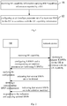
- the present disclosure provides in some embodiments a BWP configuration method applied for a network device which, as shown in Fig.1 , includes Steps 11 and 12.
- Step 11 receiving UE capability information carrying BWP capability information reported by a UE.
- the UE capability information may be used to indicate a UE air interface capability, especially the UE air interface capability based on BWPs.
- Step 12 configuring an air interface parameter set of at least one BWP for the UE in accordance with the UE capability information.
- the air interface parameter set may include at least one air interface parameter of the BWP.
- the UE may notify the network device of its own BWP-related capability through reporting UE capability, e.g., the capability of at most supporting X BWPs.
- the network device may decide to configure X BWPs for the UE in accordance with the UE capability, and further configure the X BWPs and a corresponding air interface parameter set for the UE.
- the network device may simultaneously indicate that Y of the X BWPs are to be activated, where Y is smaller than or equal to X.
- the UE may use the above-mentioned configuration.
- the BWP configuration method may further include: when it is necessary to add or modify the BWPs for the UE, transmitting information about the to-be-added or to-be-modified BWPs to the UE; and when it is necessary to delete the BWPs for the UE, transmitting information about a list of the to-be-deleted BWPs to the UE.
- the network device may further add the BWPs or modify or delete some BWPS in accordance with a real-time network communication state, a UE service requirement or a resource scheduling situation.
- the UE may delete corresponding BWP configurations.
- the UE may respond to this indication and use the updated BWPs.
- the information about the BWPs may include at least one of index information about each to-be-added or to-be-modified BWP, central frequency point information about each to-be-added or to-be-modified BWP, bandwidth information about each to-be-added or to-be-modified BWP, antenna configuration information about each to-be-added or to-be-modified BWP, numerology information about each to-be-added or to-be-modified BWP, uplink/downlink BWP configuration information corresponding to each to-be-added or to-be-modified BWP when there is a correspondence between the uplink and downlink BWPs, configuration information about a Random Access Channel (RACH) for the UE with respect to each to-be-added or to-be-modified BWP, information about a power control parameter of the UE with respect to each to-be-added or to-be-modified BWP, cross-BWP scheduling configuration information, and configuration information about
- the configuration information about the physical channel may include at least one of configuration-related information about a Physical Downlink Control Channel (PDCCH), configuration-related information about a Physical Downlink Shared Channel (PDSCH), configuration-related information about a Physical Uplink Shared Channel (PUSCH), configuration-related information about a Physical Uplink Control Channel (PUCCH), configuration-related information about a Sounding Reference Signal (SRS), configuration-related information about a Physical Random Access Channel (PRACH), configuration-related information about a Physical Broadcast Channel (PBCH), configuration-related information about a Scheduling Request (SR), configuration-related information about a reference signal such as Channel State Information Reference Signal (CSI-RS)/Tracking Reference Signal (TRS)/Phase Tracking Reference Signal (PTRS)/Demodulation Reference Signal (DMRS), and configuration-related information about a channel state report.
- CSI-RS Channel State Information Reference Signal
- TRS Tracking Reference Signal
- DMRS Demodulation Reference Signal
- the UE capability information may include at least one of: capability information about the maximum quantity of BWPs capable of being configured for the UE simultaneously for uplink or downlink transmission and a bandwidth; capability information about the maximum quantity of BWPs capable of being activated by the UE simultaneously for the uplink or downlink transmission and a bandwidth; capability information about the quantity of consecutive or inconsecutive BWPs in a same carrier capable of being configured for the UE simultaneously and a bandwidth; capability information about the quantity of consecutive or inconsecutive BWPs in a same carrier capable of being activated by the UE simultaneously and a bandwidth; capability information about the quantity of BWPs capable of being configured for the UE simultaneously in different carriers and a bandwidth in the case of Carrier Aggregation (CA); capability information about the quantity of BWPs capable of being configured for the UE simultaneously in different carriers and a bandwidth in the case of Dual Connectivity (DC); capability information about the quantity of BWPs capable of being activated by the UE simultaneously in different carriers and a bandwidth in the
- the UE capability information may be reported to the network device through joint bandwidth.
- the measurement items in the third indication information, the fourth indication information and the fifth indication information may include at least one of Reference Signal Received Power (RSRP), Reference Signal Received Quality (RSRQ), a Signal to Interference plus Noise Ratio (SINR), Received Signal Strength Indication (RSSI) and Channel Quality Indication (CQI).
- RSRP Reference Signal Received Power
- RSRQ Reference Signal Received Quality
- SINR Signal to Interference plus Noise Ratio
- RSSI Received Signal Strength Indication
- CQI Channel Quality Indication
- the UE capability in an LTE system may be X-A+Y-C, where A represents one carrier, and C represents that the UE has a capability of performing carrier aggregation on two inconsecutive carriers at a certain band.
- one carrier may be provided with a plurality of BWPs, and at this time, it is necessary to define different BWP combination types. To be specific, there may also exist a plurality of BWP combinations in a supported large-bandwidth carrier.
- the air interface parameter set may include an air interface parameter type of each BWP.
- the air interface parameter type may include at least one of: a first air interface parameter indicating that merely one BWP is capable of being configured or activated in a current carrier, i.e., merely one BWP is capable of being configured or activated in each carrier; a second air interface parameter indicating that at least two BWPs at consecutive positions are capable of being configured or activated in the current carrier, i.e., two or more BWPs at consecutive positions are capable of being configured or activated in each carrier; a third air interface parameter indicating that at least two BWPs at inconsecutive positions are capable of being configured or activated in the current carrier, i.e., two or more BWPs at inconsecutive positions are capable of being configured or activated in each carrier; a fourth air interface parameter indicating that at least three BWPs at consecutive positions and inconsecutive positions are capable of being configured or activated in the current carrier, i
- Step 12 may include: configuring, by the network device, at least one BWP and the air interface parameter set of the at least one BWP for the UE in accordance with the UE capability information; and transmitting the air interface parameter set of the at least one BWP to the UE through a broadcast message or preset signaling.
- the network device may transmit the air interface parameter set of the at least one BWP to the UE through the broadcast message or the preset signaling.
- the transmitting the air interface parameter set of the at least one BWP to the UE through the broadcast message or the preset signaling may include transmitting information about the correspondence between the uplink and downlink BWPs in the air interface parameter set of the at least one BWP to the UE through the broadcast message or the preset signaling.
- the correspondence between the uplink and downlink BWPs may be determined through the broadcast message or dedicated signaling.
- the uplink and downlink BWPs may be a BWP pair consisting of an uplink BWP and a downlink BWP.
- the information about the correspondence between the uplink and downlink BWPs may include at least one of information about a feedback relationship between the uplink and downlink BWPs, scheduling information about the uplink and downlink BWPs, information about Timing Advance (TA) of the uplink and downlink BWPs, and path loss information about the uplink and downlink BWPs.
- the information about the feedback relationship between the uplink and downlink BWPs may include the feedback relationship such as Hybrid Automatic Repeat reQuest (HARQ) feedback and a channel state.
- HARQ Hybrid Automatic Repeat reQuest
- the transmitting the information about the correspondence between the uplink and downlink BWPs in the air interface parameter set of the at least one BWP to the UE may be implemented in the following modes.
- the BWP configuration method may further include: when the information about the correspondence between the uplink and downlink BWPs indicates that one downlink BWP corresponds to a plurality of uplink feedback BWPs, modifying an uplink feedback BWP adopted by the UE for the uplink transmission through the preset signaling.
- the used BWP feedback may be modified through signaling.
- the BWP configuration method may further include: receiving request information for requesting On-demand System Information (or other System Information, OSI) from the UE; and transmitting the OSI requested by the request information to the UE in accordance with the UE capability information through the at least one BWP configured for the UE.
- OSI System Information
- the request information may carry the UE capability information about the UE.
- a procedure of requesting the OSI may include receiving the request information for requesting the OSI from the UE through a message 1 (MSG1) or a message 3 (MSG3).
- MSG1 message 1
- MSG3 message 3
- the network device When no default BWP has been indicated for the requesting of the SI and the transmission of a corresponding broadcast message and the network device does not acquire the UE capability, it is necessary to carry the BWP-related UE capability or the BWP for receiving the broadcast message in the request information for requesting the OSI included in the MSG1 or MSG3, so that the network device may determine the BWP for the transmission of the downlink broadcast message in accordance with the BWP-related UE capability.
- the UE may receive the corresponding broadcast message, and monitor the OSI.
- the BWP configuration method may further include: transmitting L1/L2/L3 measurement configuration information at a designated BWP of the at least one BWP to the UE in accordance with the air interface parameter set of the at least one BWP; receiving measurement report information reported by the UE after the measurement in accordance with the measurement configuration information; and updating the air interface parameter set for the UE in accordance with the measurement report information.
- LI represents a physical layer
- L2 represents a high layer
- L3 represents a Radio Resource Control (RRC) layer.
- RRC Radio Resource Control
- the updating the air interface parameter set for the UE in accordance with the measurement report information may include: when the measurement report information indicates that it is necessary to perform BWP switching, configuring indication information indicating whether or not to configure a measurement gap in the air interface parameter set.
- the network device wants the UE to provide the measurement item of the other BWP in a same carrier, so that the network device may determine how to switch to the other BWP.
- the BWP switching is a procedure performed at the physical layer, so an additional LI measurement item needs to be provided, and a new measurement gap corresponding to the LI measurement item needs to be configured.
- the measurement gap may be used to measure such LI measurement items as SINR/CQI.
- the network device may flexibly configure at least one BWP for the UE and the air interface parameter set of the at least one BWP in accordance with the UE capability information. As a result, it is able to configure the air interface parameters in accordance with the BWPs which cannot be solved in the related art.
- the present disclosure further provides in some embodiments a network device 400 capable of implementing the above-mentioned BWP configuration method, i.e., receiving UE capability information carrying BWP capability information reported by a UE, and configuring an air interface parameter set of at least one BWP for the UE in accordance with the UE capability information, with a same technical effect.
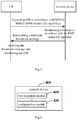
- the network device 400 includes: a first reception module 410 configured to receive the UE capability information carrying the BWP capability information reported by the UE; and a configuration module 420 configured to configure the air interface parameter set of the at least one BWP for the UE in accordance with the UE capability information.
- the air interface parameter set may include at least one air interface parameter of the BWP.
- the UE capability information may include at least one of: capability information about the maximum quantity of BWPs capable of being configured for the UE simultaneously for uplink or downlink transmission and a bandwidth; capability information about the maximum quantity of BWPs capable of being activated by the UE simultaneously for the uplink or downlink transmission and a bandwidth; capability information about the quantity of consecutive or inconsecutive BWPs in a same carrier capable of being configured for the UE simultaneously and a bandwidth; capability information about the quantity of consecutive or inconsecutive BWPs in a same carrier capable of being activated by the UE simultaneously and a bandwidth; capability information about the quantity of BWPs capable of being configured for the UE simultaneously in different carriers and a bandwidth in the case of Carrier Aggregation (CA); capability information about the quantity of BWPs capable of being configured for the UE simultaneously in different carriers and a bandwidth in the case of Dual Connectivity (DC); capability information about the quantity of BWPs capable of being activated by the UE simultaneously in different carriers and a bandwidth in the
- the measurement items may include at least one of RSRP, RSRQ, an SINR, RSSI and CQI.
- the air interface parameter set may include an air interface parameter type.
- the air interface parameter type may include at least one of: a first air interface parameter indicating that merely one BWP is capable of being configured or activated in a current carrier,; a second air interface parameter indicating that at least two BWPs at consecutive positions are capable of being configured or activated in the current carrier; a third air interface parameter indicating that at least two BWPs at inconsecutive positions are capable of being configured or activated in the current carrier; a fourth air interface parameter indicating that at least three BWPs at consecutive positions and inconsecutive positions are capable of being configured or activated in the current carrier; and a fifth air interface parameter indicating that at least one BWP at a predetermined position is capable of being configured or activated in the other carrier, the other carrier being a carrier other than the current carrier.
- the configuration module 420 may include: a configuration sub-module configured to configure at least one BWP and the air interface parameter set of the at least one BWP for the UE in accordance with the UE capability information; and a first transmission sub-module configured to transmit the air interface parameter set of the at least one BWP to the UE through a broadcast message or preset signaling.
- the first transmission sub-module may include a first transmission unit configured to transmit information about the correspondence between the uplink and downlink BWPs in the air interface parameter set of the at least one BWP to the UE through the broadcast message or the preset signaling.
- the uplink and downlink BWPs may be a BWP pair consisting of an uplink BWP and a downlink BWP.
- the information about the correspondence between the uplink and downlink BWPs may include at least one of information about a feedback relationship between the uplink and downlink BWPs, scheduling information about the uplink and downlink BWPs, information about TA of the uplink and downlink BWPs, and path loss information about the uplink and downlink BWPs.
- the first transmission unit may include: a first transmission sub-unit configured to transmit the information about the correspondence between the uplink and downlink BWPs in the air interface parameter set of the at least one BWP to the UE through carrying a configuration of one of the uplink and downlink BWPs in a configuration of the other one of the uplink and downlink BWPs; or a second transmission sub-unit configured to transmit the information about the correspondence between the uplink and downlink BWPs in the air interface parameter set of the at least one BWP to the UE through providing the uplink and downlink BWPs with a same configuration; or a third transmission sub-unit configured to transmit the information about the correspondence between the uplink and downlink BWPs in the air interface parameter set of the at least one BWP to the UE through configuring a predetermined variable.
- the first transmission sub-module may further include an indication unit configured to, when the information about the correspondence between the uplink and downlink BWPs indicates that one downlink BWP corresponds to a plurality of uplink feedback BWPs, modify an uplink feedback BWP adopted by the UE for the uplink transmission through the preset signaling.
- the network device 400 may further include: a second reception module configured to receive request information for requesting OSI from the UE, the request information carrying the UE capability information about the UE; and a first transmission module configured to transmit the OSI requested by the request information to the UE in accordance with the UE capability information through the at least one BWP configured for the UE.
- the second reception module may include a first reception sub-module configured to receive the request information for requesting the OSI from the UE through MSG1 or MSG3.
- the network device 400 may further include: a second transmission module configured to transmit L1/L2/L3 measurement configuration information at a designated BWP of the at least one BWP to the UE in accordance with the air interface parameter set of the at least one BWP; a third reception module configured to receive measurement report information reported by the UE after the measurement in accordance with the measurement configuration information; and an updating module configured to update the air interface parameter set for the UE in accordance with the measurement report information.
- a second transmission module configured to transmit L1/L2/L3 measurement configuration information at a designated BWP of the at least one BWP to the UE in accordance with the air interface parameter set of the at least one BWP
- a third reception module configured to receive measurement report information reported by the UE after the measurement in accordance with the measurement configuration information
- an updating module configured to update the air interface parameter set for the UE in accordance with the measurement report information.
- the updating module may include a first updating sub-module configured to, when the measurement report information indicates that it is necessary to perform BWP switching, configure indication information indicating whether or not to configure a measurement gap in the air interface parameter set.
- the network device 400 may further include a third transmission module configured to, when it is necessary to add or modify the BWPs for the UE, transmit information about the to-be-added or to-be-modified BWPs to the UE.
- the information about the BWPs may include at least one of index information about each to-be-added or to-be-modified BWP, central frequency point information about each to-be-added or to-be-modified BWP, bandwidth information about each to-be-added or to-be-modified BWP, antenna configuration information about each to-be-added or to-be-modified BWP, numerology information about each to-be-added or to-be-modified BWP, uplink/downlink BWP configuration information corresponding to each to-be-added or to-be-modified BWP, configuration information about an RACH for the UE with respect to each to-be-added or to-be-modified BWP, information about a power control parameter of
- the network device 400 may further include a fourth transmission module configured to, when it is necessary to delete the BWPs for the UE, transmit information about a list of the to-be-deleted BWPs to the UE.
- the network device may flexibly configure at least one BWP for the UE and the air interface parameter set of the at least one BWP in accordance with the UE capability information. As a result, it is able to configure the air interface parameters in accordance with the BWPs which cannot be solved in the related art.
- the present disclosure further provides in some embodiments a network device, including a processor, a memory, and a computer program stored in the memory and executed by the processor.
- the processor is configured to execute the computer program, so as to implement the above-mentioned BWP configuration method.
- the present disclosure further provides in some embodiments a computer-readable storage medium storing therein a computer program. The computer program is executed by a processor so as to implement the above-mentioned BWP configuration method.
- the present disclosure further provides in some embodiments a network device 500 which, as shown in Fig.5 , includes an antenna 51, a Radio Frequency (RF) unit 52, and a baseband unit 53.
- the antenna 51 is connected to the RF unit 52.
- the RF unit 52 is configured to receive information via the antenna 51, and transmit the received information to the baseband unit 53 for processing.
- the baseband unit 53 is configured to process to-be-transmitted information, and transmit the processed information to the RF unit 52.
- the RF unit 52 is configured to process the received information and transmit the processed information via the antenna 51.
- a frequency band processing unit may be located within the baseband unit 53, so that the above method for the network device may be implemented within the baseband unit 53.
- the baseband unit 53 may include a processor 54 and a memory 55.
- the baseband unit 53 may, e.g., include at least one baseband board on which a plurality of chips is located, as shown in Fig.5 .
- One chip may be, e.g., the processor 54 connected to the memory 55 and configured to call a program stored in the memory 55 so as to perform operations for the network device in the above-mentioned method embodiments.
- the baseband unit 53 may further include a network interface 56 configured to exchange information with the RF unit 52.
- the network interface may be, e.g., a Common Public Radio Interface (CPRI).
- CPRI Common Public Radio Interface
- the processor may include merely one processor, or a plurality of processing elements.
- the processor may be a CPU, an ASIC, or one or more ICs configured to implement the above-mentioned method for the network device, e.g., one or more DSPs, or one or more FPGAs.
- the memory may include merely one memory, or a plurality of storage elements.
- the memory 55 may be a volatile memory, a nonvolatile memory or both.
- the nonvolatile memory may be a Read-Only Memory (ROM), a Programmable ROM (PROM), an Erasable PROM (EPROM), an electrically EPROM (EEPROM) or a flash memory.
- the volatile memory may be a Random Access Memory (RAM) which serves as an external high-speed cache.
- the RAM may include Static RAM (SRAM), Dynamic RAM (DRAM), Synchronous DRAM (SDRAM), Double Data Rate SDRAM (DDRSDRAM), Enhanced SDRAM (ESDRAM), Synchronous Link DRAM (SLDRAM) or Direct Rambus RAM (DRRAM).
- SRAM Static RAM
- DRAM Dynamic RAM
- SDRAM Synchronous DRAM
- DDRSDRAM Double Data Rate SDRAM
- ESDRAM Enhanced SDRAM
- SLDRAM Synchronous Link DRAM
- DRRAM Direct Rambus RAM
- the memory 55 intends to include, but not limited to, the above-mentione
- the network device may further include a computer program stored in the memory 55 and executed by the processor 54.
- the processor 54 is configured to call the computer program in the memory 55 so as to implement the method executed by the modules in Fig.4 .
- the processor 54 is further configured to call the computer program, so as to: receive the UE capability information carrying the BWP capability information reported by the UE; and configure the air interface parameter set of the at least one BWP for the UE in accordance with the UE capability information.
- the air interface parameter set may include at least one air interface parameter of the BWP.
- the UE capability information may include at least one of: capability information about the maximum quantity of BWPs capable of being configured for the UE simultaneously for uplink or downlink transmission and a bandwidth; capability information about the maximum quantity of BWPs capable of being activated by the UE simultaneously for the uplink or downlink transmission and a bandwidth; capability information about the quantity of consecutive or inconsecutive BWPs in a same carrier capable of being configured for the UE simultaneously and a bandwidth; capability information about the quantity of consecutive or inconsecutive BWPs in a same carrier capable of being activated by the UE simultaneously and a bandwidth; capability information about the quantity of BWPs capable of being configured for the UE simultaneously in different carriers and a bandwidth in the case of Carrier Aggregation (CA); capability information about the quantity of BWPs capable of being configured for the UE simultaneously in different carriers and a bandwidth in the case of Dual Connectivity (DC); capability information about the quantity of BWPs capable of being activated by the UE simultaneously in different carriers and a
- CA
- the measurement items may include at least one of RSRP, RSRQ, an SINR, RSSI and CQI.
- the air interface parameter set may include an air interface parameter type.
- the air interface parameter type may include at least one of: a first air interface parameter indicating that merely one BWP is capable of being configured or activated in a current carrier; a second air interface parameter indicating that at least two BWPs at consecutive positions are capable of being configured or activated in the current carrier; a third air interface parameter indicating that at least two BWPs at inconsecutive positions are capable of being configured or activated in the current carrier; a fourth air interface parameter indicating that at least three BWPs at consecutive positions and inconsecutive positions are capable of being configured or activated in the current carrier; and a fifth air interface parameter indicating that at least one BWP at a predetermined position is capable of being configured or activated in the other carrier, the other carrier being a carrier other than the current carrier.
- the processor 54 is further configured to call the computer program so as to: configure at least one BWP and the air interface parameter set of the at least one BWP for the UE in accordance with the UE capability information; and transmit the air interface parameter set of the at least one BWP to the UE through a broadcast message or preset signaling.
- the processor 54 is further configured to call the computer program, so as to transmit information about the correspondence between the uplink and downlink BWPs in the air interface parameter set of the at least one BWP to the UE through the broadcast message or the preset signaling.
- the uplink and downlink BWPs may be a BWP pair consisting of an uplink BWP and a downlink BWP.
- the information about the correspondence between the uplink and downlink BWPs may include at least one of information about a feedback relationship between the uplink and downlink BWPs, scheduling information about the uplink and downlink BWPs, information about TA of the uplink and downlink BWPs, and path loss information about the uplink and downlink BWPs.
- the processor 54 is further configured to call the computer program so as to: transmit the information about the correspondence between the uplink and downlink BWPs in the air interface parameter set of the at least one BWP to the UE through carrying a configuration of one of the uplink and downlink BWPs in a configuration of the other one of the uplink and downlink BWPs; or transmit the information about the correspondence between the uplink and downlink BWPs in the air interface parameter set of the at least one BWP to the UE through providing the uplink and downlink BWPs with a same configuration; or transmit the information about the correspondence between the uplink and downlink BWPs in the air interface parameter set of the at least one BWP to the UE through configuring a predetermined variable.
- the processor 54 is further configured to call the computer program, so as to, when the information about the correspondence between the uplink and downlink BWPs indicates that one downlink BWP corresponds to a plurality of uplink feedback BWPs, modify an uplink feedback BWP adopted by the UE for the uplink transmission through the preset signaling.
- the processor 54 is further configured to call the computer program, so as to: receive request information for requesting OSI from the UE, the request information carrying the UE capability information about the UE; and transmit the OSI requested by the request information to the UE in accordance with the UE capability information through the at least one BWP configured for the UE.
- the processor 54 is further configured to call the computer program, so as to receive the request information for requesting the OSI from the UE through MSG1 or MSG3.
- the processor 54 is further configured to call the computer program, so as to: transmit L1/L2/L3 measurement configuration information at a designated BWP of the at least one BWP to the UE in accordance with the air interface parameter set of the at least one BWP; receive measurement report information reported by the UE after the measurement in accordance with the measurement configuration information; and update the air interface parameter set for the UE in accordance with the measurement report information.
- the processor 54 is further configured to call the computer program, so as to, when the measurement report information indicates that it is necessary to perform BWP switching, configure indication information indicating whether or not to configure a measurement gap in the air interface parameter set.
- the processor 54 is further configured to call the computer program, so as to, when it is necessary to add or modify the BWPs for the UE, transmit information about the to-be-added or to-be-modified BWPs to the UE.
- the information about the BWPs may include at least one of index information about each to-be-added or to-be-modified BWP, central frequency point information about each to-be-added or to-be-modified BWP, bandwidth information about each to-be-added or to-be-modified BWP, antenna configuration information about each to-be-added or to-be-modified BWP, numerology information about each to-be-added or to-be-modified BWP, uplink/downlink BWP configuration information corresponding to each to-be-added or to-be-modified BWP, configuration information about an RACH for the UE with respect to each to-be-added or to-be-modified BWP, information about a power control parameter of the UE with respect to each to-be-added or to-be-modified BWP, cross-BWP scheduling configuration information, and configuration information about a physical channel for the UE with respect to each to-be-added or to-be-mod
- the processor 54 is further configured to call the computer program, so as to, when it is necessary to delete the BWPs for the UE, transmit information about a list of the to-be-deleted BWPs to the UE.
- the network device may be a Base Transceiver Station (BTS) in a Global System of Mobile Communication (GSM) system or a Code Division Multiple Access (CDMA) system, a Node B (NB) in a Wideband Code Division Multiple Access (WCDMA) system, an Evolved Node B (eNB, or eNodeB) in an LTE system, a relay or an access point, or a base station in a 5G network, which will not be particularly defined herein.
- BTS Base Transceiver Station
- GSM Global System of Mobile Communication
- CDMA Code Division Multiple Access
- NB Node B
- WCDMA Wideband Code Division Multiple Access
- eNB Evolved Node B
- LTE Long Term Evolution
- relay or an access point or a base station in a 5G network
- the network device may flexibly configure at least one BWP for the UE and the air interface parameter set of the at least one BWP in accordance with the UE capability information. As a result, it is able to configure the air interface parameters in accordance with the BWPs which cannot be solved in related art.
- the present disclosure further provides in some embodiments a BWP configuration method applied for a UE, which includes the following Steps 61 and 62.
- Step 61 reporting UE capability information carrying BWP capability information to a network device.
- the UE capability information may be used to indicate a UE air interface capability, especially the UE air interface capability based on BWPs.
- Step 62 receiving an air interface parameter set of at least one BWP configured by the network device in accordance with the UE capability information.
- the air interface parameter set may include at least one air interface parameter of the BWP.
- the BWP configuration method may further include: receiving information about to-be-added or to-be-modified BWPs from the network device; and receiving information about a list of to-be-deleted BWPs from the network device.
- the network device may transmit the information about the to-be-added or to-be-modified BWPs to the UE, and when it is necessary to delete the BWPs for the UE, the network device may transmit the information about the list of the to-be-deleted BWPs to the UE.
- the information about the BWPs may include at least one of index information about each to-be-added or to-be-modified BWP, central frequency point information about each to-be-added or to-be-modified BWP, bandwidth information about each to-be-added or to-be-modified BWP, antenna configuration information about each to-be-added or to-be-modified BWP, numerology information about each to-be-added or to-be-modified BWP, uplink/downlink BWP configuration information corresponding to each to-be-added or to-be-modified BWP, configuration information about a Random Access Channel (RACH) for the UE with respect to each to-be-added or to-be-modified BWP, information about a power control parameter of the UE with respect to each to-be-added or to-be-modified BWP, cross-BWP scheduling configuration information, and configuration information about a physical channel for the UE with respect to each to-be-added
- the measurement items in the third indication information, the fourth indication information and the fifth indication information may include at least one of RSRP, RSRQ, an SINR, RSSI and CQI.
- the air interface parameter set may include an air interface parameter type.
- the air interface parameter type may include at least one of: a first air interface parameter indicating that merely one BWP is capable of being configured or activated in a current carrier,; a second air interface parameter indicating that at least two BWPs at consecutive positions are capable of being configured or activated in the current carrier; a third air interface parameter indicating that at least two BWPs at inconsecutive positions are capable of being configured or activated in the current carrier; a fourth air interface parameter indicating that at least two BWPs at different positions are capable of being configured or activated in the current carrier; and a fifth air interface parameter indicating that at least one BWP at a predetermined position is capable of being configured or activated in the other carrier, the other carrier being a carrier other than the current carrier.
- Step 62 may include receiving at least one BWP and the air interface parameter set of the at least one BWP configuredconfigured by the network device in accordance with the UE capability information through a broadcast message or preset signaling.
- Step 62 may include receiving information about a correspondence between uplink and downlink BWPs in the air interface parameter set of the at least one BWP configuredconfigured by the network device in accordance with the UE capability information.
- the uplink and downlink BWPs may be a BWP pair consisting of an uplink BWP and a downlink BWP.
- the information about the correspondence between the uplink and downlink BWPs may include at least one of information about a feedback relationship between the uplink and downlink BWPs, scheduling information about the uplink and downlink BWPs, information about TA of the uplink and downlink BWPs, and path loss information about the uplink and downlink BWPs.
- the information about the feedback relationship between the uplink and downlink BWPs may include the feedback relationship such as HARQ feedback and a channel state.
- the receiving the information about the correspondence between the uplink and downlink BWPs in the air interface parameter set of the at least one BWP configured by the network device in accordance with the UE capability information may include, but not limited to: receiving the information about the correspondence between the uplink and downlink BWPs in the air interface parameter set of the at least one BWP configured by the network device in accordance with the UE capability information through carrying a configuration of one of the uplink and downlink BWPs in a configuration of the other one of the uplink and downlink BWPs; or receiving the information about the correspondence between the uplink and downlink BWPs in the air interface parameter set of the at least one BWP configured by the network device in accordance with the UE capability information through providing the uplink and downlink BWPs with a same configuration; or receiving the information about the correspondence between the uplink and downlink BWPs in the air interface parameter set of the at least one BWP configured by the network device in accordance with the UE capability information through configuring a pre
- the BWP configuration method may further include: transmitting request information for requesting OSI to the network device in accordance with the air interface parameter set; and receiving the OSI requested by the request information from the network device through the at least one BWP configured for the UE.
- the transmitting the request information for requesting the OSI may include transmitting the request information for requesting the OSI to the network device through MSG1 or MSG3.
- the transmitting the request information for requesting the OSI may include transmitting the request information for requesting the OSI to the network device through MSG1 or MSG3.
- the network device When no default BWP has been indicated for the requesting of the SI and the transmission of a corresponding broadcast message and the network device does not acquire the UE capability, it is necessary to carry the BWP-related UE capability or the BWP for receiving the broadcast message in the request information for requesting the OSI included in at least one of the MSG1 or MSG3, so that the network device may determine the BWP for the transmission of the downlink broadcast message.
- the BWP configuration method may further include: receiving L1/L2/L3 measurement configuration information at a designated BWP of the at least one BWP from the network device; and performing measurement in accordance with the measurement configuration information to acquire measurement report information and report the measurement report information to the network device, so that the network device updates the air interface parameter set for the UE in accordance with the measurement report information.
- the UE may report its own UE capability information to the network device, so that the network deice may flexibly configure the corresponding BWP and the air interface parameter set for the UE in accordance with the UE capability information.
- the network deice may flexibly configure the corresponding BWP and the air interface parameter set for the UE in accordance with the UE capability information.
- the present disclosure further provides in some embodiments a UE 700 capable of implementing the above-mentioned BWP configuration method, i.e., reporting UE capability information carrying BWP capability information to a network device, and receiving an air interface parameter set of at least one BWP configured by the network device in accordance with the UE capability information, with a same technical effect.
- the UE 700 includes: a reporting module 710 configured to report the UE capability information carrying the BWP capability information to the network device; and a fourth reception module 720 configured to receive the air interface parameter set of at least one BWP configured by the network device in accordance with the UE capability information.
- the air interface parameter set may include at least one air interface parameter of the BWP.
- the UE capability information may include at least one of: capability information about the maximum quantity of BWPs capable of being configured for the UE simultaneously for uplink or downlink transmission and a bandwidth; capability information about the maximum quantity of BWPs capable of being activated by the UE simultaneously for the uplink or downlink transmission and a bandwidth; capability information about the quantity of consecutive or inconsecutive BWPs in a same carrier capable of being configured for the UE simultaneously and a bandwidth; capability information about the quantity of consecutive or inconsecutive BWPs in a same carrier capable of being activated by the UE simultaneously and a bandwidth; capability information about the quantity of BWPs capable of being configured for the UE simultaneously in different carriers and a bandwidth in the case of CA; capability information about the quantity of BWPs capable of being configured for the UE simultaneously in different carriers and a bandwidth in the case of DC; capability information about the quantity of BWPs capable of being activated by the UE simultaneously in different carriers and a bandwidth in the case of CA; capability information about the quantity of
- the measurement items may include at least one of RSRP, RSRQ, an SINR, RSSI and CQI.
- the air interface parameter set may include an air interface parameter type.
- the air interface parameter type may include at least one of: a first air interface parameter indicating that merely one BWP is capable of being configured or activated in a current carrier,; a second air interface parameter indicating that at least two BWPs at consecutive positions are capable of being configured or activated in the current carrier; a third air interface parameter indicating that at least two BWPs at inconsecutive positions are capable of being configured or activated in the current carrier; a fourth air interface parameter indicating that at least two BWPs at different positions are capable of being configured or activated in the current carrier; and a fifth air interface parameter indicating that at least one BWP at a predetermined position is capable of being configured or activated in the other carrier, the other carrier being a carrier other than the current carrier.
- the fourth reception module 720 may include a second reception sub-module configured to receive at least one BWP and the air interface parameter set of the at least one BWP configured by the network device in accordance with the UE capability information through a broadcast message or preset signaling.
- the second reception sub-module may include a first reception unit configured to receive information about a correspondence between uplink and downlink BWPs in the air interface parameter set of the at least one BWP configured by the network device in accordance with the UE capability information.
- the uplink and downlink BWPs may be a BWP pair consisting of an uplink BWP and a downlink BWP.
- the information about the correspondence between the uplink and downlink BWPs may include at least one of information about a feedback relationship between the uplink and downlink BWPs, scheduling information about the uplink and downlink BWPs, information about TA of the uplink and downlink BWPs, and path loss information about the uplink and downlink BWPs.
- the first reception unit may include: a first reception sub-unit configured to receive the information about the correspondence between the uplink and downlink BWPs in the air interface parameter set of the at least one BWP configured by the network device in accordance with the UE capability information through carrying a configuration of one of the uplink and downlink BWPs in a configuration of the other one of the uplink downlink BWPs; or a second reception sub-unit configured to receive the information about the correspondence between the uplink and downlink BWPs in the air interface parameter set of the at least one BWP configured by the network device in accordance with the UE capability information through providing the uplink and downlink BWPs with a same configuration; or a third reception sub-unit configured to receive the information about the correspondence between the uplink and downlink BWPs in the air interface parameter set of the at least one BWP configured by the network device in accordance with the UE capability information through configuring a predetermined variable.
- the UE 700 may include: a fifth transmission module configured to transmit request information for requesting OSI to the network device in accordance with the air interface parameter set; and a fifth reception module configured to receive the OSI requested by the request information from the network device through the at least one BWP configured for the UE.
- the fifth transmission module may include a second transmission sub-module configured to transmit the request information for requesting the OSI to the network device through MSG1 or MSG3.
- the UE 700 may further include: a sixth reception module configured to receive L1/L2/L3 measurement configuration information at a designated BWP of the at least one BWP form the network device; and a sixth transmission module configured to perform measurement in accordance with the measurement configuration information to acquire measurement report information and report the measurement report information to the network device, so that the network device updates the air interface parameter set for the UE in accordance with the measurement report information.
- a sixth reception module configured to receive L1/L2/L3 measurement configuration information at a designated BWP of the at least one BWP form the network device
- a sixth transmission module configured to perform measurement in accordance with the measurement configuration information to acquire measurement report information and report the measurement report information to the network device, so that the network device updates the air interface parameter set for the UE in accordance with the measurement report information.
- the UE 700 may further include a seventh reception module configured to receive information about to-be-added or to-be-modified BWPs from the network device.
- the information about the BWPs may include at least one of index information about each to-be-added or to-be-modified BWP, central frequency point information about each to-be-added or to-be-modified BWP, bandwidth information about each to-be-added or to-be-modified BWP, antenna configuration information about each to-be-added or to-be-modified BWP, numerology information about each to-be-added or to-be-modified BWP, uplink/downlink BWP configuration information corresponding to each to-be-added or to-be-modified BWP, configuration information about a Random Access Channel (RACH) for the UE with respect to each to-be-added or to-be-modified BWP, information about a power control parameter of the UE with respect to each to-be-added or
- the UE 700 may further include an eighth reception module configured to receive information about a list of to-be-deleted BWPs from the network device.
- the UE may report its own UE capability information to the network device, so that the network deice may flexibly configure the corresponding BWP and the air interface parameter set for the UE in accordance with the UE capability information. As a result, it is able to configure the air interface parameters in accordance with the BWPs which cannot be solved in related art.
- the above modules of the network device and the UE are divided merely on the basis of their logic functions, and in actual use, they may be completely or partially integrated into a physical entity, or physically separated from each other.
- These modules may be implemented by calling software through a processing element, or implemented in the form of hardware.
- the determination module may be a processing element arranged separately, or integrated into a chip of the above-mentioned device.
- these modules may be stored in the memory of the above-mentioned device in the form of a program code, and may be called and executed by a processing element of the above-mentioned device so as to achieve the above functions of the determination module.
- the other modules may be implemented in a similar manner.
- modules may be integrated together or arranged separately.
- the modules, units or assemblies may each of an Integrated Circuit (IC) having a signal processing capability.
- the steps of the method or the modules may be implemented through an integrated logic circuit of the processing element in the form of hardware or through instructions in the form of software.
- the above modules may be one or more ICs capable of implementing the above-mentioned method, e.g., one or more Application Specific Integrated Circuits (ASICs), one or more Digital Signal Processors (DSPs), or one or more Field Programmable Gate Array (FPGA).
- ASICs Application Specific Integrated Circuits
- DSPs Digital Signal Processors
- FPGA Field Programmable Gate Array
- the processing element may be a general-purpose processor, e.g., a Central Processing Unit (CPU) or any other processor capable of calling the program code.
- CPU Central Processing Unit
- These modules may be integrated together and implemented in the form of system-on-a-chip (SOC).
- the present disclosure further provides in some embodiments a UE, including a processor, a memory, and a computer program stored in the memory and executed by the processor.
- the processor is configured to execute the computer program, so as to implement the above-mentioned BWP configuration method.
- the present disclosure further provides in some embodiments a computer-readable storage medium storing therein a computer program. The computer program is executed by a processor so as to implement the above-mentioned BWP configuration method.
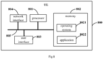
- the present disclosure further provides in some embodiments a UE 800, including at least one processor 801, a memory 802, a user interface 803 and a network interface 804.
- the components of the UE 800 may be coupled together through a bus system 805.
- the bus system 805 is configured to achieve connection and communication among the components.
- the bus system 805 may further include a power source bus, a control bus and a state signal bus.
- all these buses in Fig.8 may be collectively called as bus system 805.
- the user interface 803 may include a display, a keyboard or a pointing device (e.g., mouse, track ball, touch plate or touch panel).
- a pointing device e.g., mouse, track ball, touch plate or touch panel.
- the memory 802 may be a volatile memory, a nonvolatile memory or both.
- the nonvolatile memory may be a Read-Only Memory (ROM), a Programmable ROM (PROM), an Erasable PROM (EPROM), an electrically EPROM (EEPROM) or a flash memory.
- the volatile memory may be a Random Access Memory (RAM) which serves as an external high-speed cache.
- the RAM may include Static RAM (SRAM), Dynamic RAM (DRAM), Synchronous DRAM (SDRAM), Double Data Rate SDRAM (DDRSDRAM), Enhanced SDRAM (ESDRAM), Synchronous Link DRAM (SLDRAM) or Direct Rambus RAM (DRRAM).
- SRAM Static RAM
- DRAM Dynamic RAM
- SDRAM Synchronous DRAM
- DDRSDRAM Double Data Rate SDRAM
- ESDRAM Enhanced SDRAM
- SLDRAM Synchronous Link DRAM
- DRRAM Direct Rambus RAM
- the memory 802 intends to include, but not limited to, the above-ment
- the following elements may be stored in the memory 802: an executable module or data structure, a subset or an extended set thereof, an operating system 8021 and an application 8022.
- the operating system 8021 may include various system programs, e.g., a framework layer, a core layer and a driving layer, so as to implement various basic services and process hardware-based tasks.
- the application 8022 may include various applications, e.g., Media Player and Browser, so as to implement various application services.
- the programs for implementing the above-mentioned method may be included in the application 8022.
- the UE 800 may further include a computer program stored in the memory 802 and executed by the processor 801, e.g., a computer program in the application 8022.
- the processor 801 is configured to execute the compute program, so as to: report UE capability information carrying BWP capability information to a network device; and receive an air interface parameter set of at least one BWP configured by the network device in accordance with the UE capability information.
- the air interface parameter set may include at least one air interface parameter of the BWP.
- the above-mentioned method may be applied to, or implemented by, the processor 801.
- the processor 801 may be an integrated circuit (IC) having a signal processing capability. During the implementation, the steps of the above-mentioned method may be completed through an integrated logic circuit of hardware in the processor 801 or instructions in the form of software.
- the processor 801 may be a general-purpose processor, a digital signal processor, an application-specific integrated circuit (ASIC), a field programmable gate array (FPGA) or any other programmable logic element, a discrete gate or transistor logic element, or a discrete hardware assembly, which may be used to implement or execute the methods, steps or logic diagrams in the embodiments of the present disclosure.
- the general purpose processor may be a microprocessor or any other conventional processor.
- the steps of the method in the embodiments of the present disclosure may be directly implemented by the processor in the form of hardware, or a combination of hardware and software modules in the processor.
- the software module may be located in a known storage medium such as an RAM, a flash memory, an ROM, a PROM, an EEPROM, or a register.
- the storage medium may be located in the memory 802, and the processor 801 may read information stored in the memory 802 so as to implement the steps of the method in conjunction with the hardware.
- the embodiments of the present disclosure may be implemented by hardware, software, firmware, middleware, microcode or a combination thereof.
- the processor may include one or more of an ASIC, a DSP, a DSP device (DSPD), a Programmable Logic Device (PLD), an FPGA, a general-purpose processor, a controller, a microcontroller, a microprocessor, any other electronic unit capable of achieving the functions in the present disclosure, or a combination thereof.
- the scheme in the embodiments of the present disclosure may be implemented through modules capable of achieving the functions in the present disclosure (e.g., processes or functions).
- Software codes may be stored in the memory and executed by the processor.
- the memory may be implemented inside or outside the processor.
- the UE capability information may include at least one of: capability information about the maximum quantity of BWPs capable of being configured for the UE simultaneously for uplink or downlink transmission and a bandwidth; capability information about the maximum quantity of BWPs capable of being activated by the UE simultaneously for the uplink or downlink transmission and a bandwidth; capability information about the quantity of consecutive or inconsecutive BWPs in a same carrier capable of being configured for the UE simultaneously and a bandwidth; capability information about the quantity of consecutive or inconsecutive BWPs in a same carrier capable of being activated by the UE simultaneously and a bandwidth; capability information about the quantity of BWPs capable of being configured for the UE simultaneously in different carriers and a bandwidth in the case of Carrier Aggregation (CA); capability information about the quantity of BWPs capable of being configured for the UE simultaneously in different carriers and a bandwidth in the case of Dual Connectivity (DC); capability information about the quantity of BWPs capable of being activated by the UE simultaneously in different carriers and a
- CA
- the measurement items may include at least one of RSRP, RSRQ, an SINR, RSSI and CQI.
- the air interface parameter set may include an air interface parameter type.
- the air interface parameter type may include at least one of: a first air interface parameter indicating that merely one BWP is capable of being configured or activated in a current carrier,; a second air interface parameter indicating that at least two BWPs at consecutive positions are capable of being configured or activated in the current carrier; a third air interface parameter indicating that at least two BWPs at inconsecutive positions are capable of being configured or activated in the current carrier; a fourth air interface parameter indicating that at least two BWPs at different positions are capable of being configured or activated in the current carrier; and a fifth air interface parameter indicating that at least one BWP at a predetermined position is capable of being configured or activated in the other carrier, the other carrier being a carrier other than the current carrier.
- the processor 801 is further configured to execute the computer program, so as to receive at least one BWP and the air interface parameter set of the at least one BWP configured by the network device in accordance with the UE capability information through a broadcast message or preset signaling.
- the processor 801 is further configured to execute the computer program, so as to receive information about a correspondence between uplink and downlink BWPs in the air interface parameter set of the at least one BWP configured by the network device in accordance with the UE capability information.
- the uplink and downlink BWPs may be a BWP pair consisting of an uplink BWP and a downlink BWP.
- the information about the correspondence between the uplink and downlink BWPs may include at least one of information about a feedback relationship between the uplink and downlink BWPs, scheduling information about the uplink and downlink BWPs, information about TA of the uplink and downlink BWPs, and path loss information about the uplink and downlink BWPs.
- the processor 801 is further configured to execute the computer program, so as to: receive the information about the correspondence between the uplink and downlink BWPs in the air interface parameter set of the at least one BWP configured by the network device in accordance with the UE capability information through carrying a configuration of one of the uplink and downlink BWPs in a configuration of the other one of the uplink downlink BWPs; or receive the information about the correspondence between the uplink and downlink BWPs in the air interface parameter set of the at least one BWP configured by the network device in accordance with the UE capability information through providing the uplink and downlink BWPs with a same configuration; or receive the information about the correspondence between the uplink and downlink BWPs in the air interface parameter set of the at least one BWP configured by the network device in accordance with the UE capability information through configuring a predetermined variable.
- the processor 801 is further configured to execute the computer program, so as to: transmit request information for requesting OSI to the network device in accordance with the air interface parameter set; and receive the OSI requested by the request information from the network device through the at least one BWP configured for the UE.
- the processor 801 is further configured to execute the computer program, so as to transmit the request information for requesting the OSI to the network device through MSG1 or MSG3.
- the processor 801 is further configured to execute the computer program, so as to: receive L1/L2/L3 measurement configuration information at a designated BWP of the at least one BWP from the network device; and perform measurement in accordance with the measurement configuration information to acquire measurement report information and report the measurement report information to the network device, so that the network device updates the air interface parameter set for the UE in accordance with the measurement report information.
- the processor 801 is further configured to execute the computer program, so as to receive information about to-be-added or to-be-modified BWPs from the network device.
- the information about the BWPs may include at least one of index information about each to-be-added or to-be-modified BWP, central frequency point information about each to-be-added or to-be-modified BWP, bandwidth information about each to-be-added or to-be-modified BWP, antenna configuration information about each to-be-added or to-be-modified BWP, numerology information about each to-be-added or to-be-modified BWP, uplink/downlink BWP configuration information corresponding to each to-be-added or to-be-modified BWP, configuration information about a Random Access Channel (RACH) for the UE with respect to each to-be-added or to-be-modified BWP, information about a power control parameter of the UE with respect to each to-be-
- the processor 801 is further configured to execute the computer program, so as to receive information about a list of to-be-deleted BWPs from the network device.
- the UE may be a wireless UE or a wired UE.
- the wireless UE may be a device capable of providing voice data and/or any other service data to a user, e.g., a handheld device having a wireless connection function, or any other processing device capable of being connected to a wireless modem.
- the wireless UE may communicate with one or more core networks via a Radio Access Network (RAN).
- RAN Radio Access Network
- the wireless UE may be a mobile terminal, e.g., a mobile phone (or cellular phone), or a computer having the mobile terminal, e.g., a portable, pocket-sized, handheld, built-in or vehicle-mounted mobile device, which are capable of exchanging voice and/or data with the RAN.
- the wireless UE may be a Personal Communication Service (PCS) telephone, a cordless telephone, a Session Initiation Protocol (SIP) phone, a Wireless Local Loop (WLL) station, or a Personal Digital Assistant (PDA).
- PCS Personal Communication Service
- SIP Session Initiation Protocol
- WLL Wireless Local Loop
- PDA Personal Digital Assistant
- the wireless terminal may also be called as system, subscriber unit, subscriber station, mobile station, mobile, remote station, remote terminal, access terminal, user terminal, user agent or user device, which will not be particularly defined herein.
- the UE may report its own UE capability information to the network device, so that the network deice may flexibly configure the corresponding BWP and the air interface parameter set for the UE in accordance with the UE capability information.
- the network deice may flexibly configure the corresponding BWP and the air interface parameter set for the UE in accordance with the UE capability information.
- the device and method may be implemented in any other ways.
- the embodiments for the apparatus is merely for illustrative purposes, and the modules or units are provided merely on the basis of their logic functions. During the actual application, some modules or units may be combined together or integrated into another system. Alternatively, some functions of the module or units may be omitted or not executed.
- the coupling connection, direct coupling connection or communication connection between the modules or units may be implemented via interfaces, and the indirect coupling connection or communication connection between the modules or units may be implemented in an electrical or mechanical form or in any other form.
- the units may be, or may not be, physically separated from each other.
- the units for displaying may be, or may not be, physical units, i.e., they may be arranged at an identical position, or distributed on a plurality of network elements. Parts or all of the units may be selected in accordance with the practical need, so as to achieve the purpose of the present disclosure.
- the functional units in the embodiments of the present disclosure may be integrated into a processing unit, or the functional units may exist independently, or two or more functional units may be combined together.
- the functional units are implemented in a software form and sold or used as a separate product, they may be stored in a computer-readable medium.
- the technical solutions of the present disclosure partial or full, or parts of the technical solutions of the present disclosure contributing to the related art, may appear in the form of software products, which may be stored in a storage medium and include several instructions so as to enable computer equipment (a personal computer, a server or network equipment) to execute all or parts of the steps of the method according to the embodiments of the present disclosure.
- the storage medium includes any medium capable of storing therein program codes, e.g., a universal serial bus (USB) flash disk, a mobile hard disk (HD), a read-only memory (ROM), a random access memory (RAM), a magnetic disk or an optical disk.
- program codes e.g., a universal serial bus (USB) flash disk, a mobile hard disk (HD), a read-only memory (ROM), a random access memory (RAM), a magnetic disk or an optical disk.
- the members and/or steps may be subdivided and/or recombined, which shall also be deemed as equivalents of the present disclosure.
- the steps for executing the above-mentioned processings may be performed in a chronological order. Of course, some steps may also be performed in parallel, or independently of each other.
- the purposes of the present disclosure may also be implemented by one program or a set of programs running on any computing device, e.g., a known general-purpose computer, or implemented merely by a program product including programs codes capable of implementing the method or device.
- this program product and a storage medium storing therein the program product also constitute a part of the present disclosure.
- the storage medium may be any known storage medium or a storage medium that may occur in future.
- the members and/or steps may be subdivided and/or recombined, which shall also be deemed as equivalents of the present disclosure.
- the steps for executing the above-mentioned processings may be performed in a chronological order. Of course, some steps may also be performed in parallel, or independently of each other.
Landscapes
- Engineering & Computer Science (AREA)
- Signal Processing (AREA)
- Computer Networks & Wireless Communication (AREA)
- Databases & Information Systems (AREA)
- Environmental & Geological Engineering (AREA)
- Mobile Radio Communication Systems (AREA)
- Data Exchanges In Wide-Area Networks (AREA)
Applications Claiming Priority (2)
| Application Number | Priority Date | Filing Date | Title |
|---|---|---|---|
| CN201710687867.2A CN109391935B (zh) | 2017-08-11 | 2017-08-11 | 一种带宽部分的配置方法、网络设备及终端 |
| PCT/CN2018/099120 WO2019029510A1 (fr) | 2017-08-11 | 2018-08-07 | Procédé de configuration de partie de bande passante, équipement de réseau et terminal |
Publications (3)
| Publication Number | Publication Date |
|---|---|
| EP3668217A1 true EP3668217A1 (fr) | 2020-06-17 |
| EP3668217A4 EP3668217A4 (fr) | 2020-07-29 |
| EP3668217B1 EP3668217B1 (fr) | 2023-05-10 |
Family
ID=65273352
Family Applications (1)
| Application Number | Title | Priority Date | Filing Date |
|---|---|---|---|
| EP18843866.7A Active EP3668217B1 (fr) | 2017-08-11 | 2018-08-07 | Procédé de configuration de partie de bande passante, équipement de réseau et terminal |
Country Status (7)
| Country | Link |
|---|---|
| US (1) | US20200213066A1 (fr) |
| EP (1) | EP3668217B1 (fr) |
| CN (1) | CN109391935B (fr) |
| ES (1) | ES2947416T3 (fr) |
| HU (1) | HUE062201T2 (fr) |
| PT (1) | PT3668217T (fr) |
| WO (1) | WO2019029510A1 (fr) |
Cited By (1)
| Publication number | Priority date | Publication date | Assignee | Title |
|---|---|---|---|---|
| EP3703446B1 (fr) * | 2017-11-16 | 2022-06-15 | Guangdong Oppo Mobile Telecommunications Corp., Ltd. | Procédé de communication sans fil, dispositif terminal et dispositif de réseau |
Families Citing this family (51)
| Publication number | Priority date | Publication date | Assignee | Title |
|---|---|---|---|---|
| CN117811705A (zh) * | 2017-09-08 | 2024-04-02 | 三星电子株式会社 | 使用带宽部分配置处理无线电链路监测的方法和系统 |
| JP2020537374A (ja) * | 2017-09-15 | 2020-12-17 | オッポ広東移動通信有限公司Guangdong Oppo Mobile Telecommunications Corp., Ltd. | スケジューリング要求の構成方法、ネットワーク装置及び端末装置 |
| US11303420B2 (en) * | 2017-10-15 | 2022-04-12 | Lg Electronics Inc. | Method and device for performing initial connection in wireless communication system |
| WO2019095251A1 (fr) * | 2017-11-17 | 2019-05-23 | Qualcomm Incorporated | Conception de plan de commande de partie de bande passante dans une nouvelle radio |
| AU2018407189A1 (en) * | 2018-02-08 | 2020-10-01 | Guangdong Oppo Mobile Telecommunications Corp., Ltd. | Resource configuration method and device, and computer storage medium |
| AU2018407179A1 (en) | 2018-02-08 | 2020-10-01 | Guangdong Oppo Mobile Telecommunications Corp., Ltd. | Resource configuration method and device, and computer storage medium |
| BR112020016542A2 (pt) | 2018-02-15 | 2021-03-02 | Telefonaktiebolaget Lm Ericsson (Publ) | métodos realizados por um dispositivo sem fio e por uma estação base para realizar um procedimento de acesso aleatório, método do dispositivo sem fio, dispositivo sem fio, e, estação base. |
| CN110474735B (zh) * | 2018-05-11 | 2021-03-23 | 华为技术有限公司 | 通信方法和通信装置 |
| US11469835B2 (en) * | 2018-06-22 | 2022-10-11 | Lg Electronics Inc. | Method and apparatus for reporting an ID of specific BWP among the multiple BWPs in wireless communication system |
| EP3826209B1 (fr) * | 2018-07-25 | 2025-03-12 | Beijing Xiaomi Mobile Software Co., Ltd. | Procédé et dispositif de transmission de canal physique pour système de mtc, et support de stockage |
| CN110831210B (zh) | 2018-08-09 | 2022-07-19 | 中国移动通信有限公司研究院 | 一种资源分配方法、终端、网络设备和计算机存储介质 |
| US11950106B2 (en) * | 2018-08-09 | 2024-04-02 | Apple Inc. | User equipment capability indication of receive beamforming for cell identification |
| WO2020096987A2 (fr) * | 2018-11-05 | 2020-05-14 | Yuhan Zhou | Mécanismes de commutation de partie de bande passante (bwp) dans un réseau nouvelle radio (nr) |
| US11095419B2 (en) | 2019-01-02 | 2021-08-17 | Ofinno, Llc | Simultaneous bandwidth parts switching |
| CN111757473B (zh) * | 2019-03-28 | 2023-05-09 | 中国移动通信有限公司研究院 | 一种基于带宽部分的终端节能方法 |
| CN113557784B (zh) * | 2019-03-29 | 2024-04-12 | 富士通株式会社 | 上行传输方法、上行调度方法、装置和通信系统 |
| US11245552B2 (en) | 2019-03-29 | 2022-02-08 | Skyworks Solutions, Inc. | Sounding reference signal switching |
| CN111614443B (zh) * | 2019-05-10 | 2023-04-25 | 维沃移动通信有限公司 | 终端能力上报、信息接收方法、终端及网络设备 |
| WO2020248261A1 (fr) * | 2019-06-14 | 2020-12-17 | Oppo广东移动通信有限公司 | Procédé et appareil de détermination d'intervalle de mesure, et terminal |
| CN112312543B (zh) * | 2019-08-02 | 2024-06-21 | 北京三星通信技术研究有限公司 | 数据传输的方法及设备 |
| CN112351383B (zh) * | 2019-08-09 | 2022-07-22 | 大唐移动通信设备有限公司 | 一种定位辅助信息的请求方法、设备、装置及存储介质 |
| US11563550B2 (en) * | 2019-08-30 | 2023-01-24 | Qualcomm Incorporated | Transmission configuration indicator state activation and deactivation |
| CN112702788B (zh) * | 2019-10-23 | 2023-05-09 | 中国移动通信有限公司研究院 | 信息传输方法、装置、相关设备及存储介质 |
| CN114600411B (zh) * | 2019-10-31 | 2024-12-17 | 高通股份有限公司 | 用于增强型探通的方法和装置 |
| US11431583B2 (en) * | 2019-11-22 | 2022-08-30 | Huawei Technologies Co., Ltd. | Personalized tailored air interface |
| WO2021103026A1 (fr) * | 2019-11-30 | 2021-06-03 | 华为技术有限公司 | Procédé pour réaliser une communication sur une partie de bande passante |
| US20230050082A1 (en) * | 2019-12-31 | 2023-02-16 | Nec Corporation | Methods, devices, and medium for communication |
| US11791971B2 (en) * | 2020-01-17 | 2023-10-17 | Qualcomm Incorporated | Component carrier group based bandwidth part switching |
| WO2021142798A1 (fr) * | 2020-01-17 | 2021-07-22 | Oppo广东移动通信有限公司 | Procédé de communication d'informations, procédé d'acquisition d'informations, terminal et dispositif de réseau |
| CN116234049B (zh) | 2020-04-08 | 2026-01-06 | 北京小米移动软件有限公司 | 配置信息传输方法及装置、通信设备及存储介质 |
| WO2021216595A1 (fr) * | 2020-04-21 | 2021-10-28 | Qualcomm Incorporated | Commutation de partie de bande passante dynamique pour fonctionnement en duplex intégral dans un spectre non apparié |
| US11818724B2 (en) * | 2020-05-01 | 2023-11-14 | Qualcomm Incorporated | Communication after change in bandwidth part |
| KR20220133922A (ko) * | 2020-05-15 | 2022-10-05 | 엘지전자 주식회사 | 무선 통신을 위한 신호 송수신 방법 및 이를 위한 장치 |
| CN116506954B (zh) * | 2020-06-13 | 2025-01-10 | Oppo广东移动通信有限公司 | 一种bwp配置方法及装置、终端设备、网络设备 |
| CN113873643A (zh) * | 2020-06-30 | 2021-12-31 | 展讯通信(上海)有限公司 | 用于mbms业务的bwp配置信息确定方法及装置、存储介质、终端 |
| CN114173322A (zh) | 2020-09-10 | 2022-03-11 | 华为技术有限公司 | 一种通信方法及装置 |
| WO2022077394A1 (fr) * | 2020-10-15 | 2022-04-21 | 华为技术有限公司 | Procédé et appareil de communication |
| US20230396393A1 (en) * | 2020-10-23 | 2023-12-07 | Apple Inc. | Beam management for non-terrestrial network (ntn) |
| CN114727331B (zh) * | 2021-01-04 | 2025-08-26 | 中国移动通信有限公司研究院 | 一种数据传输方法、装置、终端及网络设备 |
| US20240073961A1 (en) * | 2021-01-12 | 2024-02-29 | Beijing Xiaomi Mobile Software Co., Ltd. | Access resource determination method, access resource determination apparatus and storage medium |
| US11765733B2 (en) * | 2021-03-31 | 2023-09-19 | Qualcomm Incorporated | Techniques for measurement gap configurations |
| CN116783915A (zh) * | 2021-05-11 | 2023-09-19 | Oppo广东移动通信有限公司 | 无线通信的方法、终端设备和网络设备 |
| US11956108B2 (en) | 2021-06-14 | 2024-04-09 | Skyworks Solutions, Inc. | Antenna swapping without blanking symbols |
| US20240032008A1 (en) * | 2021-08-04 | 2024-01-25 | Apple Inc. | User equipment capability signaling for measurement gap enhancements |
| CN116156651A (zh) * | 2021-11-17 | 2023-05-23 | 中国电信股份有限公司 | 带宽部分bwp的配置方法及相关设备 |
| CN117015062A (zh) * | 2022-04-29 | 2023-11-07 | 中国移动通信有限公司研究院 | 信息传输方法、装置、终端设备及网络侧设备 |
| CN115087006B (zh) * | 2022-06-20 | 2024-04-02 | 中国联合网络通信集团有限公司 | 一种灵活帧结构系统下行仿真方法、装置及设备 |
| CN117560657A (zh) * | 2022-08-01 | 2024-02-13 | 华为技术有限公司 | 一种能力上报方法及装置 |
| CN117641421A (zh) * | 2022-08-10 | 2024-03-01 | 维沃移动通信有限公司 | 测量处理方法、装置、终端及网络侧设备 |
| CN120019684A (zh) * | 2022-08-10 | 2025-05-16 | 株式会社Ntt都科摩 | 终端、无线通信方法以及基站 |
| CN120076072A (zh) * | 2023-11-29 | 2025-05-30 | 华为技术有限公司 | 一种通信连接的方法和装置 |
Family Cites Families (7)
| Publication number | Priority date | Publication date | Assignee | Title |
|---|---|---|---|---|
| KR20130126427A (ko) * | 2012-05-11 | 2013-11-20 | 주식회사 팬택 | 다중 요소 반송파 시스템에서 단말의 성능정보의 전송장치 및 방법 |
| US9985711B2 (en) * | 2013-08-05 | 2018-05-29 | Lg Electronics Inc. | Method and device for transmitting channel state information in wireless communication system |
| CN105099634B (zh) * | 2014-05-09 | 2019-05-07 | 中兴通讯股份有限公司 | 动态资源的分配方法及装置、基站、终端 |
| EP3335450B1 (fr) * | 2015-08-13 | 2020-12-09 | Intel IP Corporation | Rapport de capacité d'équipement utilisateur |
| US10103857B2 (en) * | 2015-09-16 | 2018-10-16 | Samsung Electronics Co., Ltd. | Signaling methods and apparatus for advanced MIMO communication systems |
| US10027396B2 (en) * | 2015-11-04 | 2018-07-17 | Lg Electronics Inc. | Method of measuring CSI in wireless communication system supporting unlicensed bands and apparatus supporting the same |
| CN106851742B (zh) * | 2015-12-04 | 2019-11-12 | 中国移动通信集团公司 | 一种在mac层实现空口调度的方法及装置 |
-
2017
- 2017-08-11 CN CN201710687867.2A patent/CN109391935B/zh active Active
-
2018
- 2018-08-07 HU HUE18843866A patent/HUE062201T2/hu unknown
- 2018-08-07 ES ES18843866T patent/ES2947416T3/es active Active
- 2018-08-07 PT PT188438667T patent/PT3668217T/pt unknown
- 2018-08-07 US US16/637,746 patent/US20200213066A1/en not_active Abandoned
- 2018-08-07 WO PCT/CN2018/099120 patent/WO2019029510A1/fr not_active Ceased
- 2018-08-07 EP EP18843866.7A patent/EP3668217B1/fr active Active
Cited By (1)
| Publication number | Priority date | Publication date | Assignee | Title |
|---|---|---|---|---|
| EP3703446B1 (fr) * | 2017-11-16 | 2022-06-15 | Guangdong Oppo Mobile Telecommunications Corp., Ltd. | Procédé de communication sans fil, dispositif terminal et dispositif de réseau |
Also Published As
| Publication number | Publication date |
|---|---|
| ES2947416T3 (es) | 2023-08-08 |
| PT3668217T (pt) | 2023-05-31 |
| WO2019029510A1 (fr) | 2019-02-14 |
| EP3668217B1 (fr) | 2023-05-10 |
| CN109391935A (zh) | 2019-02-26 |
| HUE062201T2 (hu) | 2023-10-28 |
| US20200213066A1 (en) | 2020-07-02 |
| CN109391935B (zh) | 2021-01-08 |
| EP3668217A4 (fr) | 2020-07-29 |
Similar Documents
| Publication | Publication Date | Title |
|---|---|---|
| EP3668217B1 (fr) | Procédé de configuration de partie de bande passante, équipement de réseau et terminal | |
| CN109890079B (zh) | 一种资源配置方法及其装置 | |
| US11540267B2 (en) | DCI detection method, PDCCH configuration method, and communications apparatus | |
| US11265803B2 (en) | Communication method and communications apparatus | |
| US12574950B2 (en) | Method for configuring resources for physical downlink control channel transmission, terminal device and network device | |
| CA3066296C (fr) | Procede de transmission de donnees et dispositif de terminal | |
| US11825322B2 (en) | Measurement control method, terminal, and non-transitory computer-readable storage medium | |
| US20230155660A1 (en) | UE Uplink Panel Selection Framework | |
| CN112996111B (zh) | Bwp的切换方法及设备 | |
| US20210168006A1 (en) | Uplink signal transmission method, terminal and storage medium | |
| CN114747280A (zh) | 减少与关于探测参考信号的传输功能的配置相关联的开销 | |
| KR20220051037A (ko) | 데이터 전송 방법, 단말기 디바이스 및 네트워크 디바이스 | |
| KR20210057799A (ko) | 사이드링크에서 전송 모드를 결정하는 방법, 단말 장치와 네트워크 장치 | |
| US20240305974A1 (en) | Method for measurement gap enhancement, terminal device, and computer-readable storage medium | |
| US20200128528A1 (en) | Wireless communication method and device | |
| WO2024169512A1 (fr) | Procédé de mesure et appareil de mesure | |
| EP4451735A1 (fr) | Procédé et appareil de communication | |
| WO2020154871A1 (fr) | Procédé de commande de mesure, dispositif terminal, et dispositif de réseau | |
| US20250310070A1 (en) | Configuration method and apparatus, terminal device, and network device | |
| JP2025509544A (ja) | 通信方法及び装置 | |
| CN121080088A (zh) | 用于确定上行链路发送切换的切换时段位置的系统和方法 | |
| US20210160908A1 (en) | Method for downlink signal transmission, and terminal | |
| CN115039467B (zh) | 跟踪参考信号的方法和装置 | |
| WO2020187125A1 (fr) | Procédé et dispositif de transmission de données | |
| WO2024092605A1 (fr) | Procédés et appareil de rapport de mesure de couche physique amélioré dans des communications sans fil |
Legal Events
| Date | Code | Title | Description |
|---|---|---|---|
| STAA | Information on the status of an ep patent application or granted ep patent |
Free format text: STATUS: THE INTERNATIONAL PUBLICATION HAS BEEN MADE |
|
| PUAI | Public reference made under article 153(3) epc to a published international application that has entered the european phase |
Free format text: ORIGINAL CODE: 0009012 |
|
| STAA | Information on the status of an ep patent application or granted ep patent |
Free format text: STATUS: REQUEST FOR EXAMINATION WAS MADE |
|
| 17P | Request for examination filed |
Effective date: 20200224 |
|
| AK | Designated contracting states |
Kind code of ref document: A1 Designated state(s): AL AT BE BG CH CY CZ DE DK EE ES FI FR GB GR HR HU IE IS IT LI LT LU LV MC MK MT NL NO PL PT RO RS SE SI SK SM TR |
|
| AX | Request for extension of the european patent |
Extension state: BA ME |
|
| A4 | Supplementary search report drawn up and despatched |
Effective date: 20200629 |
|
| RIC1 | Information provided on ipc code assigned before grant |
Ipc: H04L 12/24 20060101ALI20200623BHEP Ipc: H04W 72/04 20090101AFI20200623BHEP Ipc: H04W 8/24 20090101ALI20200623BHEP Ipc: H04W 24/02 20090101ALI20200623BHEP |
|
| DAV | Request for validation of the european patent (deleted) | ||
| DAX | Request for extension of the european patent (deleted) | ||
| STAA | Information on the status of an ep patent application or granted ep patent |
Free format text: STATUS: EXAMINATION IS IN PROGRESS |
|
| 17Q | First examination report despatched |
Effective date: 20210528 |
|
| REG | Reference to a national code |
Ref country code: DE Ref legal event code: R079 Ref document number: 602018049771 Country of ref document: DE Free format text: PREVIOUS MAIN CLASS: H04W0072040000 Ipc: H04L0041089600 |
|
| GRAP | Despatch of communication of intention to grant a patent |
Free format text: ORIGINAL CODE: EPIDOSNIGR1 |
|
| STAA | Information on the status of an ep patent application or granted ep patent |
Free format text: STATUS: GRANT OF PATENT IS INTENDED |
|
| RIC1 | Information provided on ipc code assigned before grant |
Ipc: H04L 43/0876 20220101ALI20221202BHEP Ipc: H04L 41/0853 20220101ALI20221202BHEP Ipc: H04L 41/0896 20220101AFI20221202BHEP |
|
| INTG | Intention to grant announced |
Effective date: 20221221 |
|
| GRAS | Grant fee paid |
Free format text: ORIGINAL CODE: EPIDOSNIGR3 |
|
| GRAA | (expected) grant |
Free format text: ORIGINAL CODE: 0009210 |
|
| STAA | Information on the status of an ep patent application or granted ep patent |
Free format text: STATUS: THE PATENT HAS BEEN GRANTED |
|
| AK | Designated contracting states |
Kind code of ref document: B1 Designated state(s): AL AT BE BG CH CY CZ DE DK EE ES FI FR GB GR HR HU IE IS IT LI LT LU LV MC MK MT NL NO PL PT RO RS SE SI SK SM TR |
|
| REG | Reference to a national code |
Ref country code: GB Ref legal event code: FG4D |
|
| REG | Reference to a national code |
Ref country code: AT Ref legal event code: REF Ref document number: 1567839 Country of ref document: AT Kind code of ref document: T Effective date: 20230515 Ref country code: CH Ref legal event code: EP |
|
| REG | Reference to a national code |
Ref country code: DE Ref legal event code: R096 Ref document number: 602018049771 Country of ref document: DE |
|
| REG | Reference to a national code |
Ref country code: PT Ref legal event code: SC4A Ref document number: 3668217 Country of ref document: PT Date of ref document: 20230531 Kind code of ref document: T Free format text: AVAILABILITY OF NATIONAL TRANSLATION Effective date: 20230525 |
|
| REG | Reference to a national code |
Ref country code: IE Ref legal event code: FG4D |
|
| REG | Reference to a national code |
Ref country code: NL Ref legal event code: FP |
|
| REG | Reference to a national code |
Ref country code: SK Ref legal event code: T3 Ref document number: E 41666 Country of ref document: SK |
|
| REG | Reference to a national code |
Ref country code: ES Ref legal event code: FG2A Ref document number: 2947416 Country of ref document: ES Kind code of ref document: T3 Effective date: 20230808 |
|
| P01 | Opt-out of the competence of the unified patent court (upc) registered |
Effective date: 20230712 |
|
| REG | Reference to a national code |
Ref country code: LT Ref legal event code: MG9D |
|
| REG | Reference to a national code |
Ref country code: AT Ref legal event code: MK05 Ref document number: 1567839 Country of ref document: AT Kind code of ref document: T Effective date: 20230510 |
|
| REG | Reference to a national code |
Ref country code: HU Ref legal event code: AG4A Ref document number: E062201 Country of ref document: HU |
|
| PG25 | Lapsed in a contracting state [announced via postgrant information from national office to epo] |
Ref country code: SE Free format text: LAPSE BECAUSE OF FAILURE TO SUBMIT A TRANSLATION OF THE DESCRIPTION OR TO PAY THE FEE WITHIN THE PRESCRIBED TIME-LIMIT Effective date: 20230510 Ref country code: NO Free format text: LAPSE BECAUSE OF FAILURE TO SUBMIT A TRANSLATION OF THE DESCRIPTION OR TO PAY THE FEE WITHIN THE PRESCRIBED TIME-LIMIT Effective date: 20230810 Ref country code: AT Free format text: LAPSE BECAUSE OF FAILURE TO SUBMIT A TRANSLATION OF THE DESCRIPTION OR TO PAY THE FEE WITHIN THE PRESCRIBED TIME-LIMIT Effective date: 20230510 |
|
| PG25 | Lapsed in a contracting state [announced via postgrant information from national office to epo] |
Ref country code: RS Free format text: LAPSE BECAUSE OF FAILURE TO SUBMIT A TRANSLATION OF THE DESCRIPTION OR TO PAY THE FEE WITHIN THE PRESCRIBED TIME-LIMIT Effective date: 20230510 Ref country code: PL Free format text: LAPSE BECAUSE OF FAILURE TO SUBMIT A TRANSLATION OF THE DESCRIPTION OR TO PAY THE FEE WITHIN THE PRESCRIBED TIME-LIMIT Effective date: 20230510 Ref country code: LV Free format text: LAPSE BECAUSE OF FAILURE TO SUBMIT A TRANSLATION OF THE DESCRIPTION OR TO PAY THE FEE WITHIN THE PRESCRIBED TIME-LIMIT Effective date: 20230510 Ref country code: LT Free format text: LAPSE BECAUSE OF FAILURE TO SUBMIT A TRANSLATION OF THE DESCRIPTION OR TO PAY THE FEE WITHIN THE PRESCRIBED TIME-LIMIT Effective date: 20230510 Ref country code: IS Free format text: LAPSE BECAUSE OF FAILURE TO SUBMIT A TRANSLATION OF THE DESCRIPTION OR TO PAY THE FEE WITHIN THE PRESCRIBED TIME-LIMIT Effective date: 20230910 Ref country code: HR Free format text: LAPSE BECAUSE OF FAILURE TO SUBMIT A TRANSLATION OF THE DESCRIPTION OR TO PAY THE FEE WITHIN THE PRESCRIBED TIME-LIMIT Effective date: 20230510 Ref country code: GR Free format text: LAPSE BECAUSE OF FAILURE TO SUBMIT A TRANSLATION OF THE DESCRIPTION OR TO PAY THE FEE WITHIN THE PRESCRIBED TIME-LIMIT Effective date: 20230811 |
|
| PG25 | Lapsed in a contracting state [announced via postgrant information from national office to epo] |
Ref country code: FI Free format text: LAPSE BECAUSE OF FAILURE TO SUBMIT A TRANSLATION OF THE DESCRIPTION OR TO PAY THE FEE WITHIN THE PRESCRIBED TIME-LIMIT Effective date: 20230510 |
|
| PG25 | Lapsed in a contracting state [announced via postgrant information from national office to epo] |
Ref country code: SM Free format text: LAPSE BECAUSE OF FAILURE TO SUBMIT A TRANSLATION OF THE DESCRIPTION OR TO PAY THE FEE WITHIN THE PRESCRIBED TIME-LIMIT Effective date: 20230510 Ref country code: RO Free format text: LAPSE BECAUSE OF FAILURE TO SUBMIT A TRANSLATION OF THE DESCRIPTION OR TO PAY THE FEE WITHIN THE PRESCRIBED TIME-LIMIT Effective date: 20230510 Ref country code: EE Free format text: LAPSE BECAUSE OF FAILURE TO SUBMIT A TRANSLATION OF THE DESCRIPTION OR TO PAY THE FEE WITHIN THE PRESCRIBED TIME-LIMIT Effective date: 20230510 Ref country code: DK Free format text: LAPSE BECAUSE OF FAILURE TO SUBMIT A TRANSLATION OF THE DESCRIPTION OR TO PAY THE FEE WITHIN THE PRESCRIBED TIME-LIMIT Effective date: 20230510 Ref country code: CZ Free format text: LAPSE BECAUSE OF FAILURE TO SUBMIT A TRANSLATION OF THE DESCRIPTION OR TO PAY THE FEE WITHIN THE PRESCRIBED TIME-LIMIT Effective date: 20230510 |
|
| REG | Reference to a national code |
Ref country code: DE Ref legal event code: R097 Ref document number: 602018049771 Country of ref document: DE |
|
| PG25 | Lapsed in a contracting state [announced via postgrant information from national office to epo] |
Ref country code: MC Free format text: LAPSE BECAUSE OF FAILURE TO SUBMIT A TRANSLATION OF THE DESCRIPTION OR TO PAY THE FEE WITHIN THE PRESCRIBED TIME-LIMIT Effective date: 20230510 |
|
| PLBE | No opposition filed within time limit |
Free format text: ORIGINAL CODE: 0009261 |
|
| STAA | Information on the status of an ep patent application or granted ep patent |
Free format text: STATUS: NO OPPOSITION FILED WITHIN TIME LIMIT |
|
| PG25 | Lapsed in a contracting state [announced via postgrant information from national office to epo] |
Ref country code: MC Free format text: LAPSE BECAUSE OF FAILURE TO SUBMIT A TRANSLATION OF THE DESCRIPTION OR TO PAY THE FEE WITHIN THE PRESCRIBED TIME-LIMIT Effective date: 20230510 |
|
| PG25 | Lapsed in a contracting state [announced via postgrant information from national office to epo] |
Ref country code: LU Free format text: LAPSE BECAUSE OF NON-PAYMENT OF DUE FEES Effective date: 20230807 |
|
| 26N | No opposition filed |
Effective date: 20240213 |
|
| PG25 | Lapsed in a contracting state [announced via postgrant information from national office to epo] |
Ref country code: LU Free format text: LAPSE BECAUSE OF NON-PAYMENT OF DUE FEES Effective date: 20230807 |
|
| PG25 | Lapsed in a contracting state [announced via postgrant information from national office to epo] |
Ref country code: SI Free format text: LAPSE BECAUSE OF FAILURE TO SUBMIT A TRANSLATION OF THE DESCRIPTION OR TO PAY THE FEE WITHIN THE PRESCRIBED TIME-LIMIT Effective date: 20230510 |
|
| REG | Reference to a national code |
Ref country code: BE Ref legal event code: MM Effective date: 20230831 |
|
| PG25 | Lapsed in a contracting state [announced via postgrant information from national office to epo] |
Ref country code: SI Free format text: LAPSE BECAUSE OF FAILURE TO SUBMIT A TRANSLATION OF THE DESCRIPTION OR TO PAY THE FEE WITHIN THE PRESCRIBED TIME-LIMIT Effective date: 20230510 |
|
| PG25 | Lapsed in a contracting state [announced via postgrant information from national office to epo] |
Ref country code: BE Free format text: LAPSE BECAUSE OF NON-PAYMENT OF DUE FEES Effective date: 20230831 |
|
| PG25 | Lapsed in a contracting state [announced via postgrant information from national office to epo] |
Ref country code: BG Free format text: LAPSE BECAUSE OF FAILURE TO SUBMIT A TRANSLATION OF THE DESCRIPTION OR TO PAY THE FEE WITHIN THE PRESCRIBED TIME-LIMIT Effective date: 20230510 |
|
| PG25 | Lapsed in a contracting state [announced via postgrant information from national office to epo] |
Ref country code: BG Free format text: LAPSE BECAUSE OF FAILURE TO SUBMIT A TRANSLATION OF THE DESCRIPTION OR TO PAY THE FEE WITHIN THE PRESCRIBED TIME-LIMIT Effective date: 20230510 |
|
| PGFP | Annual fee paid to national office [announced via postgrant information from national office to epo] |
Ref country code: GB Payment date: 20250626 Year of fee payment: 8 |
|
| PG25 | Lapsed in a contracting state [announced via postgrant information from national office to epo] |
Ref country code: CY Free format text: LAPSE BECAUSE OF FAILURE TO SUBMIT A TRANSLATION OF THE DESCRIPTION OR TO PAY THE FEE WITHIN THE PRESCRIBED TIME-LIMIT; INVALID AB INITIO Effective date: 20180807 |
|
| PGFP | Annual fee paid to national office [announced via postgrant information from national office to epo] |
Ref country code: NL Payment date: 20250704 Year of fee payment: 8 |
|
| PGFP | Annual fee paid to national office [announced via postgrant information from national office to epo] |
Ref country code: HU Payment date: 20250728 Year of fee payment: 8 |
|
| PGFP | Annual fee paid to national office [announced via postgrant information from national office to epo] |
Ref country code: ES Payment date: 20250909 Year of fee payment: 8 Ref country code: PT Payment date: 20250807 Year of fee payment: 8 |
|
| PGFP | Annual fee paid to national office [announced via postgrant information from national office to epo] |
Ref country code: DE Payment date: 20250702 Year of fee payment: 8 |
|
| PGFP | Annual fee paid to national office [announced via postgrant information from national office to epo] |
Ref country code: IT Payment date: 20250722 Year of fee payment: 8 |
|
| PGFP | Annual fee paid to national office [announced via postgrant information from national office to epo] |
Ref country code: FR Payment date: 20250703 Year of fee payment: 8 |
|
| PGFP | Annual fee paid to national office [announced via postgrant information from national office to epo] |
Ref country code: CH Payment date: 20250901 Year of fee payment: 8 |
|
| PGFP | Annual fee paid to national office [announced via postgrant information from national office to epo] |
Ref country code: IE Payment date: 20250702 Year of fee payment: 8 |
|
| PGFP | Annual fee paid to national office [announced via postgrant information from national office to epo] |
Ref country code: SK Payment date: 20250714 Year of fee payment: 8 |
|
| PG25 | Lapsed in a contracting state [announced via postgrant information from national office to epo] |
Ref country code: TR Free format text: LAPSE BECAUSE OF FAILURE TO SUBMIT A TRANSLATION OF THE DESCRIPTION OR TO PAY THE FEE WITHIN THE PRESCRIBED TIME-LIMIT Effective date: 20230510 |