EP3668228A1 - Procédé d'envoi, procédé de réception, dispositif et système pour des signaux de référence de sondage - Google Patents
Procédé d'envoi, procédé de réception, dispositif et système pour des signaux de référence de sondage Download PDFInfo
- Publication number
- EP3668228A1 EP3668228A1 EP18852334.4A EP18852334A EP3668228A1 EP 3668228 A1 EP3668228 A1 EP 3668228A1 EP 18852334 A EP18852334 A EP 18852334A EP 3668228 A1 EP3668228 A1 EP 3668228A1
- Authority
- EP
- European Patent Office
- Prior art keywords
- srs
- sending
- resource
- terminal device
- uplink data
- Prior art date
- Legal status (The legal status is an assumption and is not a legal conclusion. Google has not performed a legal analysis and makes no representation as to the accuracy of the status listed.)
- Granted
Links
Images







Classifications
-
- H—ELECTRICITY
- H04—ELECTRIC COMMUNICATION TECHNIQUE
- H04L—TRANSMISSION OF DIGITAL INFORMATION, e.g. TELEGRAPHIC COMMUNICATION
- H04L5/00—Arrangements affording multiple use of the transmission path
- H04L5/003—Arrangements for allocating sub-channels of the transmission path
- H04L5/0048—Allocation of pilot signals, i.e. of signals known to the receiver
-
- H—ELECTRICITY
- H04—ELECTRIC COMMUNICATION TECHNIQUE
- H04W—WIRELESS COMMUNICATION NETWORKS
- H04W72/00—Local resource management
- H04W72/20—Control channels or signalling for resource management
- H04W72/23—Control channels or signalling for resource management in the downlink direction of a wireless link, i.e. towards a terminal
-
- H—ELECTRICITY
- H04—ELECTRIC COMMUNICATION TECHNIQUE
- H04L—TRANSMISSION OF DIGITAL INFORMATION, e.g. TELEGRAPHIC COMMUNICATION
- H04L25/00—Baseband systems
- H04L25/02—Details ; arrangements for supplying electrical power along data transmission lines
- H04L25/0202—Channel estimation
- H04L25/0224—Channel estimation using sounding signals
- H04L25/0226—Channel estimation using sounding signals sounding signals per se
-
- H—ELECTRICITY
- H04—ELECTRIC COMMUNICATION TECHNIQUE
- H04L—TRANSMISSION OF DIGITAL INFORMATION, e.g. TELEGRAPHIC COMMUNICATION
- H04L1/00—Arrangements for detecting or preventing errors in the information received
-
- H—ELECTRICITY
- H04—ELECTRIC COMMUNICATION TECHNIQUE
- H04L—TRANSMISSION OF DIGITAL INFORMATION, e.g. TELEGRAPHIC COMMUNICATION
- H04L1/00—Arrangements for detecting or preventing errors in the information received
- H04L1/0001—Systems modifying transmission characteristics according to link quality, e.g. power backoff
- H04L1/0023—Systems modifying transmission characteristics according to link quality, e.g. power backoff characterised by the signalling
- H04L1/0027—Scheduling of signalling, e.g. occurrence thereof
-
- H—ELECTRICITY
- H04—ELECTRIC COMMUNICATION TECHNIQUE
- H04L—TRANSMISSION OF DIGITAL INFORMATION, e.g. TELEGRAPHIC COMMUNICATION
- H04L5/00—Arrangements affording multiple use of the transmission path
-
- H—ELECTRICITY
- H04—ELECTRIC COMMUNICATION TECHNIQUE
- H04L—TRANSMISSION OF DIGITAL INFORMATION, e.g. TELEGRAPHIC COMMUNICATION
- H04L5/00—Arrangements affording multiple use of the transmission path
- H04L5/0001—Arrangements for dividing the transmission path
- H04L5/0003—Two-dimensional division
- H04L5/0005—Time-frequency
- H04L5/0007—Time-frequency the frequencies being orthogonal, e.g. OFDM(A) or DMT
-
- H—ELECTRICITY
- H04—ELECTRIC COMMUNICATION TECHNIQUE
- H04L—TRANSMISSION OF DIGITAL INFORMATION, e.g. TELEGRAPHIC COMMUNICATION
- H04L5/00—Arrangements affording multiple use of the transmission path
- H04L5/003—Arrangements for allocating sub-channels of the transmission path
- H04L5/0044—Allocation of payload; Allocation of data channels, e.g. PDSCH or PUSCH
-
- H—ELECTRICITY
- H04—ELECTRIC COMMUNICATION TECHNIQUE
- H04L—TRANSMISSION OF DIGITAL INFORMATION, e.g. TELEGRAPHIC COMMUNICATION
- H04L5/00—Arrangements affording multiple use of the transmission path
- H04L5/003—Arrangements for allocating sub-channels of the transmission path
- H04L5/0048—Allocation of pilot signals, i.e. of signals known to the receiver
- H04L5/0051—Allocation of pilot signals, i.e. of signals known to the receiver of dedicated pilots, i.e. pilots destined for a single user or terminal
-
- H—ELECTRICITY
- H04—ELECTRIC COMMUNICATION TECHNIQUE
- H04L—TRANSMISSION OF DIGITAL INFORMATION, e.g. TELEGRAPHIC COMMUNICATION
- H04L5/00—Arrangements affording multiple use of the transmission path
- H04L5/003—Arrangements for allocating sub-channels of the transmission path
- H04L5/0078—Timing of allocation
-
- H—ELECTRICITY
- H04—ELECTRIC COMMUNICATION TECHNIQUE
- H04L—TRANSMISSION OF DIGITAL INFORMATION, e.g. TELEGRAPHIC COMMUNICATION
- H04L5/00—Arrangements affording multiple use of the transmission path
- H04L5/0091—Signalling for the administration of the divided path, e.g. signalling of configuration information
- H04L5/0092—Indication of how the channel is divided
-
- H—ELECTRICITY
- H04—ELECTRIC COMMUNICATION TECHNIQUE
- H04W—WIRELESS COMMUNICATION NETWORKS
- H04W28/00—Network traffic management; Network resource management
- H04W28/02—Traffic management, e.g. flow control or congestion control
- H04W28/0278—Traffic management, e.g. flow control or congestion control using buffer status reports
-
- H—ELECTRICITY
- H04—ELECTRIC COMMUNICATION TECHNIQUE
- H04W—WIRELESS COMMUNICATION NETWORKS
- H04W72/00—Local resource management
- H04W72/04—Wireless resource allocation
-
- H—ELECTRICITY
- H04—ELECTRIC COMMUNICATION TECHNIQUE
- H04W—WIRELESS COMMUNICATION NETWORKS
- H04W72/00—Local resource management
- H04W72/12—Wireless traffic scheduling
-
- H—ELECTRICITY
- H04—ELECTRIC COMMUNICATION TECHNIQUE
- H04L—TRANSMISSION OF DIGITAL INFORMATION, e.g. TELEGRAPHIC COMMUNICATION
- H04L5/00—Arrangements affording multiple use of the transmission path
- H04L5/0091—Signalling for the administration of the divided path, e.g. signalling of configuration information
- H04L5/0094—Indication of how sub-channels of the path are allocated
-
- H—ELECTRICITY
- H04—ELECTRIC COMMUNICATION TECHNIQUE
- H04L—TRANSMISSION OF DIGITAL INFORMATION, e.g. TELEGRAPHIC COMMUNICATION
- H04L5/00—Arrangements affording multiple use of the transmission path
- H04L5/0091—Signalling for the administration of the divided path, e.g. signalling of configuration information
- H04L5/0096—Indication of changes in allocation
Definitions
- This application relates to the field of communications technologies, and in particular, to a sounding reference signal (sounding reference signal, SRS) sending method, a sounding reference signal receiving method, an apparatus, and a system.
- SRS sounding reference signal
- one of main methods for obtaining uplink channel quality is that a network side device measures an SRS sent by a terminal device, to perform channel estimation to obtain the uplink channel quality.
- SRS sending solutions are defined in an LTE system: a periodic SRS sending solution and an aperiodic SRS sending solution.
- the periodic SRS sending solution is as follows:
- the network side device configures, for the terminal device by using higher layer signaling, a periodic SRS resource used to send an SRS. After receiving the higher layer signaling, the terminal device starts to periodically send the SRS on the SRS resource. To be specific, starting from receiving the higher layer signaling, the terminal device sends the SRS once every preset time period until the SRS resource is released.
- the network side device may continuously obtain the uplink channel quality by using the periodic SRS, to ensure that the network side device can obtain a relatively high throughput gain when the terminal device sends a relatively large data packet or when the terminal device needs to continuously send data.
- the terminal device does not have data needing to be transmitted for most of the time. If the foregoing periodic SRS sending solution is still used, the terminal device still sends the SRS when the terminal device does not transmit data. These SRSs are useless, and consequently, a resource waste is caused.
- This application provides an SRS sending method, an SRS receiving method, an apparatus, and a system, to improve SRS resource utilization and reduce resource waste.
- this application provides an SRS sending method, applied to a terminal device.
- the method includes: receiving SRS configuration information sent by a network side device, where the SRS configuration information includes first-type indication information used to instruct the terminal device to trigger, based on uplink data, sending of an SRS; and once there is the uplink data needing to be transmitted, sending the SRS on an SRS resource.
- the terminal device is enabled to send the SRS only when the terminal device has the uplink data needing to be transmitted. This avoids sending the SRS when the terminal device has no data to be transmitted, thereby improving SRS resource utilization, and reducing resource waste.
- the sending the SRS on an SRS resource includes: sending the SRS on each SRS resource that is between a first moment and a second moment, where the first moment is a moment at which the uplink data is detected or a buffer status report BSR is detected, and the second moment is a moment at which downlink control information that is sent by the network side and that corresponds to the uplink data is received.
- the terminal device may send the SRS on each SRS resource that is between the first moment and the second moment, so that the network side device can continuously obtain uplink channel quality before delivering the downlink control information for the uplink data, to ensure reliability of scheduling information allocated to the uplink data.
- the sending the SRS on an SRS resource includes: sending the SRS on K SRS resources that are after a first moment, where the first moment is a moment at which the uplink data is detected or a BSR is detected, K ⁇ 1, and K is an integer.
- the terminal device may send the SRS on the first K SRS resources that are after the first moment.
- the sent SRS may be used by the network side device to estimate uplink channel quality, or may be used to request, in place of a scheduling request (scheduling request, SR), resource scheduling from the network device.
- SR scheduling request
- the terminal device may send an SRS on each SRS resource during the period when the uplink data is transmitted, thereby enhancing robustness of a system, and improving accuracy of performing uplink channel quality estimation by the network side device.
- the SRS may be sent on M or N SRS resources that are during the period when the uplink data is transmitted, thereby further improving SRS resource utilization, and reducing resource waste.
- the sending the SRS on the K SRS resources that are during a period when the uplink data is transmitted includes: sending the SRS on the last K SRS resources that are during the period when the uplink data is transmitted.
- the SRS is sent on the last K SRS resources that are during the period when the uplink data is transmitted, so that the terminal device can improve SRS resource utilization and reduce resource waste while ensuring accuracy of uplink channel quality estimation.
- the method further includes: receiving control information sent by the network side device, where the control information is used to instruct to determine, in each SRS resource period based on whether there is uplink data, whether to skip the SRS resource period; and once there is the uplink data needing to be transmitted, the sending the SRS on an SRS resource includes: if there is the uplink data, sending the SRS on the SRS resource that is in the SRS resource period; and if there is no uplink data, skipping the SRS resource period.
- the terminal device may determine, in each SRS resource period based on whether there is the uplink data needing to be transmitted, to send the SRS or skip the SRS resource period. This avoids sending a useless SRS when there is no uplink data, thereby improving SRS resource utilization, and reducing resource waste.
- this application provides an SRS receiving method, applied to a network side device.
- the method includes: sending SRS configuration information to a terminal device, where the SRS configuration information includes first-type indication information used to instruct the terminal device to trigger, based on uplink data, sending of an SRS; and receiving the SRS that is sent by the terminal device based on the SRS configuration information.
- the network side device instructs, by using the first-type indication information in the SRS configuration information, the terminal device to send the SRS when there is the uplink data needing to be transmitted. This avoids sending the SRS when the terminal device has no data to be transmitted, thereby improving SRS resource utilization, and reducing resource waste.
- this application provides an SRS sending method, applied to a terminal device.
- the method includes: receiving SRS configuration information and control information that are sent by a network side device, where the SRS configuration information includes second-type indication information used to instruct the terminal device to trigger, based on higher layer signaling, sending of an SRS, and the control information is used to instruct the terminal device to determine, in each SRS resource period based on whether there is uplink data, whether to skip the SRS resource period; if there is the uplink data, sending the SRS on the SRS resource that is in the SRS resource period; and if there is no uplink data, skipping the SRS resource period.
- the terminal device sends the SRS only in a SRS resource period that has uplink data needing to be transmitted, and does not send the SRS in a SRS resource period that has no uplink data needing to be transmitted. This avoids sending the SRS when the terminal device has no data to be transmitted, thereby improving SRS resource utilization, and reducing resource waste.
- this application further provides an SRS receiving method, applied to a network side device.
- the method includes: sending SRS configuration information and control information to a terminal device, where the SRS configuration information includes second-type indication information used to instruct the terminal device to trigger, based on higher layer signaling, sending of an SRS, and the control information is used to instruct the terminal device to determine, in each SRS resource period based on whether there is uplink data, whether to skip the SRS resource period; and receiving the SRS that is sent by the terminal device based on the SRS configuration information and the control information.
- the network side device instructs, by using the SRS configuration information and the control information, the terminal device to send the SRS only in a SRS resource period that has the uplink data needing to be transmitted, and send no SRS in a SRS resource period that has no uplink data needing to be transmitted. This avoids sending the SRS when the terminal device has no data to be transmitted, thereby improving SRS resource utilization, and reducing resource waste.
- this application provides a terminal device, including: a receiving unit, configured to receive sounding reference signal SRS configuration information sent by a network side device, where the SRS configuration information includes first-type indication information used to instruct a sending unit to trigger, based on uplink data, sending of an SRS; a buffer unit, configured to buffer the uplink data; and the sending unit, configured to: once there is the uplink data needing to be transmitted in the buffer unit, send the SRS on the SRS resource.
- the sending, by the sending unit, the SRS on the SRS resource specifically includes: sending the SRS on each SRS resource that is between a first moment and a second moment, where the first moment is a moment at which the uplink data is detected or a BSR is detected, and the second moment is a moment at which downlink control information that is sent by the network side device and that corresponds to the uplink data is received.
- the sending, by the sending unit, the SRS on the SRS resource specifically includes: sending the SRS on K SRS resources that are after a first moment, where the first moment is a moment at which the uplink data is detected or a BSR is detected, K ⁇ 1, and K is an integer.
- the sending, by the sending unit, the SRS on the K SRS resources that are during a period when the uplink data is transmitted specifically includes: sending the SRS on the last K SRS resources that are during the period when the uplink data is transmitted.
- the receiving unit is further configured to: receive control information sent by the network side device, where the control information is used to instruct to determine, in each SRS resource period based on whether there is the uplink data, whether to skip the SRS resource period; and once the buffer unit buffers the uplink data needing to be transmitted, the sending, by the sending unit, the SRS on the SRS resource specifically includes: if the buffer unit buffers the uplink data, the sending unit sends the SRS on the SRS resource that is in the SRS resource period; and if the buffer unit has no uplink data, the sending unit skips the SRS resource period.
- this application provides a network side device, including: a sending unit, configured to send SRS configuration information to a terminal device, where the SRS configuration information includes first-type indication information used to instruct the terminal device to trigger, based on uplink data, sending of an SRS; and a receiving unit, configured to receive the SRS that is sent by the terminal device based on the SRS configuration information.
- this application provides a terminal device, including: a receiving unit, configured to receive SRS configuration information and control information that are sent by a network side device, where the SRS configuration information includes second-type indication information used to instruct a sending unit to trigger, based on higher layer signaling, sending of an SRS, and the control information is used to instruct the terminal device to determine, in each SRS resource period based on whether there is uplink data, whether to skip the SRS resource period; and the sending unit, configured to: if there is the uplink data, send the SRS on the SRS resource that is in the SRS resource period; and if there is no uplink data, skip the SRS resource period.
- this application provides a network side device, including: a sending unit, configured to send SRS configuration information and control information to a terminal device, where the SRS configuration information includes second-type indication information used to instruct the terminal device to trigger, based on higher layer signaling, sending of an SRS, and the control information is used to instruct the terminal device to determine, in each SRS resource period based on whether there is uplink data, whether to skip the SRS resource period; and a receiving unit, configured to receive the SRS that is sent by the terminal device based on the SRS configuration information and the control information.
- a sum of bandwidths of M SRS resources is equal to a bandwidth of a grant-based GB resource, or a sum of bandwidths of N SRS resources is equal to a total bandwidth available for the SRS resource, where M ⁇ 1, M is an integer, N ⁇ 1, and N is an integer.
- the SRS configuration information further includes configuration information of the SRS resource.
- this application further provides a terminal device, including: a processor, a memory, and a transceiver.
- the memory is configured to store a computer-executable instruction; the transceiver is configured to receive SRS configuration information, and send an SRS and uplink data; and the processor is connected to the memory and the transceiver by using the bus.
- the processor executes the computer-executable instruction stored in the memory, to implement the SRS sending method according to the first aspect and the implementations of the first aspect.
- this application further provides a network side device, including: a processor, a memory, and a transceiver.
- the memory is configured to store a computer-executable instruction; the transceiver is configured to send SRS configuration information, and receive an SRS and uplink data; and the processor is connected to the memory and the transceiver by using the bus.
- the processor executes the computer-executable instruction stored in the memory, to implement the receiving method for an SRS according to the second aspect.
- this application provides a terminal device, including: a processor, a memory, and a transceiver.
- the memory is configured to store a computer-executable instruction;
- the transceiver is configured to receive SRS configuration information and control information, and send an SRS and uplink data;
- the processor is connected to the memory and the transceiver by using the bus.
- the processor executes the computer-executable instruction stored in the memory, to implement the SRS sending method according to the third aspect and the implementations of the third aspect.
- this application further provides a network side device, including: a processor, a memory, and a transceiver.
- the memory is configured to store a computer-executable instruction;
- the transceiver is configured to send SRS configuration information and control information, and receive an SRS and uplink data; and the processor is connected to the memory and the transceiver by using the bus.
- the processor executes the computer-executable instruction stored in the memory, to implement the SRS receiving method according to the fourth aspect.
- this application further provides a computer storage medium.
- the computer storage medium stores an instruction, and when the instruction is run on a computer, the computer is enabled to perform the method according to the first aspect, the second aspect, the third aspect, or the fourth aspect.
- this application further provides a computer program product including an instruction.
- the computer program product When the computer program product is run on a computer, the computer is enabled to perform the method according to the first aspect, the second aspect, the third aspect, or the fourth aspect.
- this application provides a communications system, including the terminal device according to the fifth aspect or any optional manner of the fifth aspect and the network side device according to the sixth aspect or the tenth aspect; or including the terminal device according to the seventh aspect and the network side device according to the eighth aspect or the twelfth aspect; or including the terminal device according to the ninth aspect and the network side device according to the sixth aspect or the tenth aspect; or including the terminal device according to the eleventh aspect and the network side device according to the eighth aspect or the twelfth aspect.
- An SRS sending method provided in this application may be applicable to a long term evolution (long term evolution, LTE) system, a long term evolution-advanced (LTE advanced, LTE-A) system, a subsequent evolved system using the LTE system such as a 5th generation communications (5G) system, and other wireless communications systems that use various wireless access technologies.
- LTE long term evolution
- LTE advanced LTE-A
- 5G 5th generation communications
- an SRS sending method provided in this application may be applied to a communications system including at least one network side device and at least one terminal device.
- the network side device may be a base station (base station, BS) or a base transceiver station (base transceiver station, BTS), and is an apparatus that is deployed in a radio access network and that is configured to provide a wireless communication function for the terminal device.
- base station base station
- BTS base transceiver station
- a device having a base station function may have different names.
- the device in an LTE system, the device is referred to as an evolved NodeB (evolved NodeB, eNB or eNodeB), and in a 3rd generation communications (3G) network, the device is referred to as a Node B (Node B), or is applied to a 5th generation communications system, or the like.
- Node B Node B
- the devices that have a base station function and that are mentioned above are collectively referred to as a network side device.
- the terminal device in this application may include various devices that have a wireless communication function, for example, a handheld device, an in-vehicle device, a wearable device, a computing device, a smartphone, a smartwatch, a tablet or another processing device connected to a wireless modem, and user equipment (user equipment, UE), a mobile station (mobile station, MS), a terminal (terminal), and the like that are in various forms.
- a terminal device for example, a handheld device, an in-vehicle device, a wearable device, a computing device, a smartphone, a smartwatch, a tablet or another processing device connected to a wireless modem, and user equipment (user equipment, UE), a mobile station (mobile station, MS), a terminal (terminal), and the like that are in various forms.
- UE user equipment
- MS mobile station
- terminal terminal
- FIG. 2 is a network side device according to this application.
- the network side device includes a remote radio unit (remote radio unit, RRU), a baseband processing unit (baseband unit, BBU), and an antenna feeder system.
- RRU remote radio unit
- BBU baseband processing unit
- antenna feeder system an antenna feeder system.
- the RRU includes a digital intermediate frequency module, a transceiver module, and a power amplification module and a filtering module.
- the digital intermediate frequency module is configured for modulation and demodulation of an electromagnetic wave transmission signal, digital up/down conversion, A/D conversion, and the like; the transceiver module completes conversion from an intermediate frequency signal to a radio frequency signal; and then the radio frequency signal is transmitted by using an antenna port after passing through the power amplification module and the filtering module.
- the BBU is configured to: perform functions such as channel coding and decoding, modulation and demodulation of a baseband signal, and protocol processing, provide an interface function to an upper-layer network element, and complete a processing process of a physical layer core technology, for example, code division multiple access (code division multiple access, CDMA) in the 3G and orthogonal frequency division multiplexing (orthogonal frequency division multiplexing, OFDM)/multiple-input multiple-output (multiple-input multiple-output, MIMO) processing in the LTE.
- CDMA code division multiple access
- OFDM orthogonal frequency division multiplexing
- MIMO multiple-input multiple-output
- the antenna feeder system mainly includes an antenna, and may further include a coupler, a diplexer, and the like, and is configured for data transmission between another network element (for example, UE or a network side device in another cell) and the RRU.
- FIG. 3 is a terminal device according to this application, including a processor, a memory, an RF circuit, and the like.
- the processor is a control center of the terminal device, is connected to each part of the entire terminal device by using various interfaces and lines, and performs various functions of the terminal device and data processing by running or executing a software program and/or a module that are/is stored in the memory and by invoking data stored in the memory, to perform overall monitoring on the terminal device.
- the processor may include a digital signal processor device, a microprocessor device, an analog-to-digital converter, a digital-to-analog converter, and the like, and control and signal processing functions of the terminal device can be allocated to these devices based on capabilities of these devices.
- the RF circuit may be configured to send and receive information, and send received information to the processor for processing.
- the RF circuit includes but is not limited to an antenna, at least one amplifier, a transceiver, a coupler, a low noise amplifier (low noise amplifier, LNA), a duplexer, and the like, and communicates with a network and another device by using wireless communication.
- Any communications standard or protocol may be used by the wireless communication, including but not limited to a global system for mobile communications (global system of mobile communication, GSM), a general packet radio service (general packet radio service, GPRS), CDMA, wideband code division multiple access (wideband code division multiple access, WCDMA), LTE, Wi-Fi, or low power consumption Wi-Fi, a WLAN technology, and the like.
- FIG. 4 is a flowchart of an embodiment of an SRS sending method according to this application, and the method includes the following steps.
- Step 401 A network side device sends SRS configuration information, where the SRS configuration information includes first-type indication information used to instruct a terminal device to trigger, based on uplink data, sending of an SRS.
- the SRS configuration information may include only the first-type indication information.
- the SRS configuration information is the first-type indication information.
- the terminal device may trigger, based on the uplink data, sending of the SRS on a previously configured SRS resource or a predetermined SRS resource.
- the previously configured SRS resource is an SRS resource that has been configured, before the network side device sends the SRS configuration information, for the terminal device by using other configuration information.
- the predetermined SRS resource is an SRS resource specified by a standard protocol.
- the previously configured SRS resource may alternatively be replaced with a subsequently configured SRS resource.
- the SRS resource is configured, after the network device sends the SRS configuration information, by the network device by using other configuration information.
- the SRS configuration information may further include configuration information of the SRS resource.
- the configuration information of the SRS resource indicates a specific position of the SRS resource.
- the SRS resource is a resource used to send the SRS, and the resource includes at least one of a frequency-domain resource and a time-domain resource.
- the network side device may set a trigger type (trigger type) indicator bit in the SRS configuration information, and instruct, by using different assignments, the terminal device to send the SRS in different trigger manners.
- the terminal device After receiving the SRS configuration information, the terminal device triggers sending of the SRS only when there is the uplink data needing to be sent. If there is no uplink data needing to be sent, the terminal device does not trigger sending of the SRS.
- the terminal device after receiving the SRS configuration information, the terminal device triggers sending of the SRS only when there is new uplink data needing to be sent.
- the new uplink data is uplink data that has not been sent, and may be understood as uplink data that needs to be initially transmitted.
- the network side device may add the SRS configuration information to higher layer signaling, and send the higher layer signaling to the terminal device.
- the higher layer signaling may be a broadcast message, a common radio resource control (radio resource control, RRC) message, or a user dedicated RRC message.
- RRC radio resource control
- the SRS configuration information includes the configuration information of the SRS resource
- an SRS resource configured by using the SRS configuration information that is carried in the higher layer signaling may be in an available state by default (that is, a state in which the SRS can be sent).
- the SRS resource configured by using the SRS configuration information that is carried in the higher layer signaling is not in an available state, and needs to be activated by using an underlying control signal such as downlink control information (downlink control information, DCI).
- the network side device may further deactivate, by using the underlying control signal, an SRS resource that is of the terminal device and that has been in an available state.
- the activating the SRS resource means that the SRS resource is enabled to be in an available state
- the deactivating the SRS resource means that the SRS resource is enabled to be in an unavailable state.
- Step 402. Once the terminal device has the uplink data needing to be transmitted, the terminal device sends the SRS on the SRS resource.
- the terminal device after receiving the SRS configuration information, determines, based on the first type indication information, that the terminal device determines, based on whether there is the uplink data needing to be transmitted in an uplink buffer corresponding to a media access control (media access control, MAC) entity of the terminal device, whether to trigger sending of the SRS. For example, when the uplink buffer has the uplink data, the terminal device may directly trigger sending of the SRS.
- media access control media access control
- the MAC entity of the terminal device may trigger sending of a BSR, and when at least one BSR is triggered and is not canceled, sending of the SRS may be triggered, so that the terminal device starts to prepare to send the SRS on the SRS resource indicated by the SRS configuration message.
- a bandwidth of the SRS resource sent by the terminal device may be configured by the network side device.
- a sum of bandwidths of M SRS resources is equal to a bandwidth of a grant-based (grant-based, GB) resource; or a sum of bandwidths of N SRS resources is equal to a total bandwidth available for the SRS resource, where M ⁇ 1, M is an integer, N ⁇ 1, and N is an integer.
- the SRR does not need to be sent on physical uplink control channels (physical uplink control channel, PUCCH) on two sides of a system bandwidth
- PUCCH physical uplink control channel
- the terminal device may send the SRS on each SRS resource that is between a first moment and a second moment.
- the first moment is a moment at which the terminal device detects the uplink data or detects the BSR.
- the second moment is a moment at which the terminal device receives downlink control information (for example, DCI delivered by the network side device for the uplink data, including a downlink resource, HARQ information, and the like that are allocated for the uplink data) that is sent by the network side and that corresponds to the uplink data.
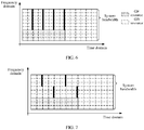
- the terminal device may send the SRS in each slot in which the SRS resource is configured.
- each block with a dashed line represents one resource block (resource block, RB).
- resource block resource block
- One RB represents 12 subcarriers in frequency domain (which is the vertical axis shown in FIG. 5 ), and represents one subframe in time domain (which is the horizontal axis shown in FIG. 5 ).
- two subframes are a period of the SRS resource (referred to as an SRS period for short below), and the SRS resource is located in the last OFDM symbol of the second subframe in each SRS period.
- RB specification related in this application is merely an example, and there may be another RB specification. This is not limited in this application.
- the terminal device may also send the SRS on K SRS resources that are after the first moment, K>1, and K is an integer.
- the terminal device sends the SRS on the K SRS resources that are after the first moment.
- Scenario 1 It is assumed that the network side device preconfigures a grant-free (grant free, GF) resource, so that when the terminal device has the uplink data needing to be transmitted, the terminal device can directly transmit the uplink data on the GF resource without waiting for the network side device to deliver scheduling information for the uplink data (that is, to perform GF data transmission). If a period of the GF resource (a time domain length of a GF resource) is greater than or equal to the SRS period (a time domain interval length of two adjacent time domain resources), the terminal device may send the SRS on K resources that are during a period of transmitting the uplink data by using the GF resource. In other words, the terminal device may send the SRS on K SRS resources that are during the GF data transmission.
- a grant-free (grant free, GF) resource a grant-free (grant free, GF) resource, so that when the terminal device has the uplink data needing to be transmitted, the terminal device can directly transmit the uplink data on the GF resource without
- the network side device may configure the SRS resource and the GF resource by using same higher layer signaling, or may configure the SRS resource and the GF resource by using different higher layer signaling.
- the SRS configuration information may be a part of a GF resource configuration message.
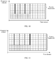
- the GF resource includes eight subframes in time domain, and includes 36 subcarriers in frequency domain. That is, a bandwidth of the GF resource is equal to three RB bandwidths. Two subframes are an SRS period, and the SRS resource is located in the last OFDM symbol of the second subframe in each SRS period. There are four SRS resources that are during the period of the GF resource. A total bandwidth available for the SRS resource is nine RB bandwidths. In a GF data transmission process of the terminal device, a bandwidth of the GB resource is equal to the total bandwidth available for the SRS resource minus the bandwidth of the GF resource, that is, equal to six RB bandwidths.
- the terminal device may send the SRS on each SRS resource during the period of transmitting the uplink data, thereby enhancing robustness of a system, and improving accuracy of performing uplink channel quality estimation by the network side device.
- the terminal device may send SRSs on four SRS resources shown in FIG. 7 in a frequency hopping manner, so that the four sent SRSs completely cover the frequency band of the GB resource.
- a schematic diagram of sending an SRS by the terminal device may be shown in FIG. 8 .
- the terminal device may send SRSs on four SRS resources shown in FIG. 9 in a frequency hopping manner, so that the four sent SRSs completely cover the total bandwidth available for the SRS resource.
- the terminal device when the SRS resource and the GF resource have an overlapping part in frequency domain, in a period of transmitting the uplink data, the terminal device does not send the uplink data on an OFDM symbol that is used to send the SRS and that is on the GF resource.
- the terminal device may send the SRS on any M SRS resources that are during the period of transmitting the uplink data.
- the terminal device may send the SRS on the first SRS resource.
- the terminal device may also send the SRS on the last SRS resource.
- the terminal device may send SRSs on the first two SRS resources in a frequency hopping manner.
- the terminal device may send SRSs on the last two SRS resources in a frequency hopping manner. So that the two sent SRSs completely cover the frequency band of the GB resource during GF data transmission.
- the terminal device may send the SRS on any N SRS resources that are during the period of transmitting the uplink data.
- the terminal device may send the SRS on the first SRS resource.
- the terminal device may also send the SRS on the last SRS resource.
- the terminal device may send SRSs on the first three SRS resources in a frequency hopping manner.
- the terminal device may send SRSs on the last three SRS resources in a frequency hopping manner. So that the sent three SRSs completely cover the total bandwidth available for the SRS resource.
- the terminal device when the terminal device has the uplink data needing to be transmitted, the terminal device can transmit the uplink data on a preconfigured GF resource.
- the terminal device sends the SRS for one or more times based on an SRS resource configured by the network side device. Therefore, the network side device may estimate uplink channel quality based on these SRSs, so that when the network side device switches the GF data transmission to GB data transmission, the network side device can deliver scheduling information that is more suitable for the estimated uplink channel quality.
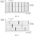
- the GF resource includes two subframes in time domain, and includes 36 subcarriers in frequency domain.
- a bandwidth of the GF resource is equal to three RB bandwidths.
- Three subframes are an SRS period, and the SRS resource is located in the last OFDM symbol of the third subframe in each SRS period.
- the total bandwidth available for the SRS resource is equal to nine RB bandwidths.
- the terminal device may send the SRS on the first SRS resource that is after the first moment.
- N 3.
- a frequency band of each three consecutive SRS resources completely covers the total bandwidth available for the SRS resource, and the terminal device may send, in a frequency hopping manner, the SRS on the first three SRS resources that are after the first moment, so that the three SRSs completely cover the total bandwidth available for the SRS resource.
- the terminal device performs conventional GB data transmission. That is, the network side device does not preconfigure the GF resource, and the terminal device needs to transmit the uplink data on the GB resource.
- the terminal device may send the SRS on the first SRS resource that is after the first moment.
- N 3
- the terminal device may send, in a frequency hopping manner, the SRS on the first three SRS resources that are after the first moment, so that the three SRSs completely cover the total bandwidth available for the SRS resource.
- the terminal device may independently trigger sending of the SRS, and send the SRS on the first K SRS resources that are after the first moment.
- the sent SRS may be used by the network side device to estimate uplink channel quality, or may be used to request, in place of a scheduling request (scheduling request, SR), resource scheduling from the network device (that is, after receiving the SRS, the network side device may learn of that the terminal device has the uplink data needing to be sent).
- SR scheduling request
- the K SRS resources ensure that there is an SRS signal being sent on the total bandwidth available for the SRS resource.
- another SRS sending manner may be further used. For example, after the first moment, an SRS may be sent in a combination mode of any bandwidth size of the SRS resource and any K value.
- the terminal device may alternatively send the SRS on the first SRS resource that is after the first moment, that is, send one SRS.
- FIG. 22 is a flowchart of another embodiment of an SRS sending method according to this application.
- Step 2201. A network side device sends SRS configuration information and control information to a terminal device.
- the SRS configuration information includes second-type indication information used to instruct the terminal device to trigger, based on higher layer signaling, sending of an SRS.
- the control information is used to instruct the terminal device to determine, in each SRS resource period based on whether there is uplink data, whether to skip the SRS resource period.
- the SRS configuration information may further include configuration information of the SRS resource.
- the network side device may configure the SRS configuration information and the control information in the higher layer signaling.
- the control information may be a control field, and when the control field is "true", the control information may instruct the terminal device to determine, in each SRS resource period based on whether there is the uplink data in an uplink buffer of the terminal device, whether to skip the SRS resource period.
- the terminal device is instructed to send the SRS in a higher layer signaling triggering manner.
- the network side device sends the higher layer signaling that configures the SRS configuration information and the control information, to send the SRS configuration information and the control information to the terminal device.
- Step 2202. If there is the uplink data, the terminal device sends the SRS on an SRS resource that is in the SRS resource period.
- the terminal device may send, based on the second-type indication information, the SRS in the higher layer signaling triggering manner.
- the terminal device may start to periodically send the SRS on the SRS resource.
- the terminal device determines, in each SRS resource period based on an indication of the control information, whether there is the uplink data in the uplink buffer of the terminal device. Once there is the uplink data, the terminal device sends the SRS on the SRS resource that is in the SRS resource period; otherwise, the terminal device skips the SRS resource period.
- the skipping the SRS resource period means skipping sending the SRS on the SRS resource that is in the period.
- an SRS sending manner of determining, based on whether the uplink data needs to be transmitted in the SRS resource period, whether to skip the SRS resource period may be essentially considered as an SRS sending manner of triggering sending of the SRS based on the uplink data.
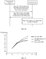
- FIG. 23 is a schematic diagram of a throughput comparison result.
- FIG. 24 is a schematic diagram of packet loss rate comparison.
- FIG. 25 is a schematic diagram of delay comparison.
- an SRS is sent only when there is uplink data needing to be transmitted in an uplink buffer of the terminal device. This avoids sending the SRS when the terminal device has no data to be transmitted, thereby improving SRS resource utilization and reducing resource waste.
- the network elements for example, the terminal device and the network side devices, include corresponding hardware structures and/or software modules for performing the functions.
- the network elements for example, the terminal device and the network side devices, include corresponding hardware structures and/or software modules for performing the functions.
- a person skilled in the art should easily be aware that, units and algorithms steps in the examples described with reference to the embodiments disclosed in this specification, may be implemented in a form of hardware or a combination of hardware and computer software in this application. Whether a function is performed by hardware or hardware driven by computer software depends on particular applications and design constraints of the technical solutions. A person skilled in the art may use different methods to implement the described functions for each particular application, but it should not be considered that the implementation goes beyond the scope of this application.
- each functional module may be divided corresponding to each function, or two or more functions may be integrated into one processing module.
- the integrated module may be implemented in a form of hardware, or may be implemented in a form of a software functional module. It should be noted that, in this application, module division is an example, and is merely logical function division. In actual implementation, another division manner may be used.
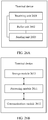
- FIG. 26A is a possible schematic structural diagram of the terminal device in the foregoing embodiments.
- the terminal device includes: a receiving unit 2601, a buffer unit 2602, and a sending unit 2603.
- the receiving unit 2601 is configured to support the terminal device in performing step 401 in FIG. 4 and/or step 2201 in FIG. 22 ;
- the buffer unit 2602 is configured to buffer uplink data;
- the sending unit 2603 is configured to support the terminal device in performing step 402 in FIG. 4 and/or steps 2202 and 2203 in FIG. 22 . All related content of the steps in the foregoing method embodiments may be cited in function descriptions of a corresponding function module, and details are not described herein again.
- FIG. 26B is a possible schematic structural diagram of the terminal device in the foregoing embodiments.
- the terminal device includes a processing module 2611 and a communications module 2612.
- the processing module 2611 is configured to control and manage an action of the terminal device.
- the processing module 2611 is configured to support the terminal device in performing steps 401 and 402 in FIG. 4 , steps 2201 to 2203 in FIG. 22 , and/or another process used for the technology described in this specification.
- the communications module 2612 is configured to support the terminal device in communicating with another network entity, for example, communicating with a function module or a network entity shown in FIG. 1 .
- the terminal device may further include a storage module 2613, configured to store program code and data of the terminal device.
- the processing module 2611 may be a processor or a controller, for example, may be a central processing unit (central processing unit, CPU), a general-purpose processor, a digital signal processor (digital signal processor, DSP), an application-specific integrated circuit (application-specific integrated circuit, ASIC), a field programmable gate array (field programmable gate array, FPGA), or another programmable logic device, a transistor logic device, a hardware component, or any combination thereof.
- the processing module may implement or execute various example logical blocks, modules, and circuits described with reference to content disclosed in this application.
- the processor may further be a combination implementing a computing function, for example, a combination of one or more microprocessors, or a combination of the DSP and a microprocessor.
- the communications module 2612 may be a transceiver, a transceiver circuit, a communications interface, or the like.
- the storage module 2613 may be a memory.
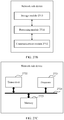
- the terminal device in this application may be the terminal device shown in FIG. 26C .
- the terminal device includes a processor 2621, a transceiver 2622, a memory 2623, and a bus 2624.
- the transceiver 2622, the processor 2621, and the memory 2623 are connected to each other by using the bus 2624.
- the bus 2624 may be a peripheral component interconnect standard (peripheral component interconnect, PCI) bus, an extended industry standard architecture (extended industry standard architecture, EISA) bus, or the like.
- PCI peripheral component interconnect
- EISA extended industry standard architecture
- the bus may be classified into an address bus, a data bus, a control bus, and the like. For ease of representation, only one thick line is used to represent the bus in FIG. 26C , but this does not mean that there is only one bus or only one type of bus.
- FIG. 27A is a possible schematic structural diagram of the network side device in the foregoing embodiments.
- the network side device includes: a sending unit 2701 and a receiving unit 2702.
- the sending unit 2701 is configured to support the network side device in performing step 401 in FIG. 4 and/or step 2201 in FIG. 22 ;
- the receiving unit 2702 is configured to support the network side device in performing step 402 in FIG. 4 and/or steps 2202 and 2203 in FIG. 22 . All related content of the steps in the foregoing method embodiments may be cited in function descriptions of a corresponding function module, and details are not described herein again.
- FIG. 27B is a possible schematic structural diagram of the network side device in the foregoing embodiments.
- the network side device includes a processing module 2711 and a communications module 2712.
- the processing module 2711 is configured to control and manage an action of the network side device.
- the processing module 2711 is configured to support the network side device in performing steps 401 and 402 in FIG. 4 , steps 2201 to 2203 in FIG. 22 , and/or another process used for the technology described in this specification.
- the communications module 2712 is configured to support the network side device in communicating with another network entity, for example, communicating with a function module or a network entity shown in FIG. 1 .
- the network side device may further include a storage module 2713, configured to store program code and data of the network side device.
- the processing module 2711 may be a processor or a controller, for example, may be a CPU, a general purpose processor, a DSP, an ASIC, an FPGA, or another programmable logic device, a transistor logic device, a hardware component, or any combination thereof.
- the processing module may implement or execute various example logical blocks, modules, and circuits described with reference to content disclosed in this application.
- the processor may further be a combination implementing a computing function, for example, a combination of one or more microprocessors, or a combination of the DSP and a microprocessor.
- the communications module 2712 may be a transceiver, a transceiver circuit, a communications interface, or the like.
- the storage module 2713 may be a memory.
- the network side device in this application may be the network side device shown in FIG. 27C .
- the network side device includes a processor 2721, a transceiver 2722, a memory 2723, and a bus 2724.
- the transceiver 2722, the processor 2721, and the memory 2723 are connected to each other by using the bus 2724.
- the bus 2724 may be a PCI bus, an EISA bus, or the like.
- the bus may be classified into an address bus, a data bus, a control bus, and the like. For ease of representation, only one thick line is used to represent the bus in FIG. 27C , but this does not mean that there is only one bus or only one type of bus.
- the software instruction may include a corresponding software module.
- the software module may be stored in a random access memory (random access memory, RAM), a flash memory, a read-only memory (read only memory, ROM), an erasable programmable read-only memory (erasable programmable ROM, EPROM), an electrically erasable programmable read-only memory (electrically EPROM, EEPROM), a register, a hard disk, a mobile hard disk, a compact disc read-only memory (CD-ROM), or any other form of storage medium well-known in the art.
- a storage medium is coupled to a processor, so that the processor can read information from the storage medium or write information into the storage medium.
- the storage medium may also be a component of the processor.
- the processor and the storage medium may be located in the ASIC.
- the ASIC may be located in a core network interface device.
- the processor and the storage medium may also exist in the core network interface device as discrete components.
- this application further provides a computer storage medium, where the computer storage medium may store a program, and when the program is executed, some or all of the steps of the embodiments of the SRS sending method or the SRS receiving method provided in this application may be included.
- the storage medium may be a magnetic disk, an optical disc, a read-only storage memory, a random access memory (random access memory, RAM), or the like.
- This application further provides a computer program product including an instruction, and when the computer program product is run on a computer, the computer is enabled to perform some or all of the steps in the embodiments of the SRS sending method or the SRS receiving method provided in this application.
- the computer software product may be stored in a storage medium, such as a ROM/RAM, a magnetic disk, or an optical disc, and includes several instructions for enabling a computer device (which may be a personal computer, a server, or a VPN gateway) to perform the methods described in the embodiments or in some parts of the embodiments of the present invention.
- a computer device which may be a personal computer, a server, or a VPN gateway
Landscapes
- Engineering & Computer Science (AREA)
- Signal Processing (AREA)
- Computer Networks & Wireless Communication (AREA)
- Power Engineering (AREA)
- Quality & Reliability (AREA)
- Mobile Radio Communication Systems (AREA)
Applications Claiming Priority (2)
| Application Number | Priority Date | Filing Date | Title |
|---|---|---|---|
| CN201710774658.1A CN109429346B (zh) | 2017-08-31 | 2017-08-31 | 一种探测参考信号的发送方法、接收方法、装置及系统 |
| PCT/CN2018/103031 WO2019042330A1 (fr) | 2017-08-31 | 2018-08-29 | Procédé d'envoi, procédé de réception, dispositif et système pour des signaux de référence de sondage |
Publications (3)
| Publication Number | Publication Date |
|---|---|
| EP3668228A1 true EP3668228A1 (fr) | 2020-06-17 |
| EP3668228A4 EP3668228A4 (fr) | 2020-08-19 |
| EP3668228B1 EP3668228B1 (fr) | 2022-04-27 |
Family
ID=65512854
Family Applications (1)
| Application Number | Title | Priority Date | Filing Date |
|---|---|---|---|
| EP18852334.4A Active EP3668228B1 (fr) | 2017-08-31 | 2018-08-29 | Procédé d'envoi, procédé de réception, dispositif et système pour des signaux de référence de sondage |
Country Status (4)
| Country | Link |
|---|---|
| US (1) | US11424964B2 (fr) |
| EP (1) | EP3668228B1 (fr) |
| CN (1) | CN109429346B (fr) |
| WO (1) | WO2019042330A1 (fr) |
Families Citing this family (8)
| Publication number | Priority date | Publication date | Assignee | Title |
|---|---|---|---|---|
| WO2019140681A1 (fr) * | 2018-01-22 | 2019-07-25 | Zte Corporation | Configuration de multiples transmissions |
| WO2020029675A1 (fr) * | 2018-08-10 | 2020-02-13 | Telefonaktiebolaget Lm Ericsson (Publ) | Procédé et appareil de transmission de signal de référence de sondage |
| CN111865388B (zh) | 2019-04-30 | 2022-04-05 | 华为技术有限公司 | 一种上行波束管理方法及装置 |
| CN111600691B (zh) * | 2019-06-05 | 2022-04-15 | 维沃移动通信有限公司 | 非授权频段的探测参考信号的传输方法和设备 |
| EP4013145A4 (fr) * | 2019-08-08 | 2023-03-22 | Ntt Docomo, Inc. | Terminal et procédé de communication sans fil |
| EP4264893B1 (fr) * | 2020-12-18 | 2025-10-08 | Telefonaktiebolaget LM Ericsson (publ) | Commande d'émission de signaux de référence |
| CN115134199B (zh) * | 2021-03-29 | 2025-03-07 | 维沃移动通信有限公司 | Srs的发送方法、接收方法、配置方法及装置 |
| CN115175326B (zh) * | 2021-04-02 | 2026-02-27 | 维沃移动通信有限公司 | 上行传输方法、装置、终端、网络侧设备和存储介质 |
Family Cites Families (13)
| Publication number | Priority date | Publication date | Assignee | Title |
|---|---|---|---|---|
| WO2011083746A1 (fr) * | 2010-01-08 | 2011-07-14 | Sharp Kabushiki Kaisha | Procédé et système de communication mobile pour la transmission d'un signal de référence de sondage, et station de base, équipement utilisateur et circuit intégré incorporés |
| KR101807875B1 (ko) | 2010-03-05 | 2017-12-12 | 엘지전자 주식회사 | 무선 통신 시스템에서 비주기적 사운딩 참조 신호 전송 방법 및 장치 |
| CN102340800B (zh) * | 2010-07-16 | 2015-08-19 | 华为技术有限公司 | 获取dci指示的信息的方法、ue及基站 |
| AU2014265044B2 (en) * | 2010-10-04 | 2016-05-19 | Ntt Docomo, Inc. | Radio base station apparatus, mobile terminal apparatus and radio communication method |
| JP2014505414A (ja) * | 2011-01-07 | 2014-02-27 | 富士通株式会社 | サウンディングリファレンス信号を送信する方法、基地局及びユーザ装置 |
| WO2012110688A1 (fr) * | 2011-02-18 | 2012-08-23 | Nokia Corporation | Procédé et appareil destinés à fournir un signal de référence sonore apériodique |
| WO2013110331A1 (fr) * | 2012-01-25 | 2013-08-01 | Fujitsu Limited | Canal de liaison montante pour communication sans fil |
| US10735166B2 (en) * | 2015-05-29 | 2020-08-04 | Huawei Technologies Co., Ltd. | System and method of UE-centric radio access procedure |
| CN106455092B (zh) * | 2015-08-13 | 2019-11-22 | 中国移动通信集团公司 | 信道探测参考信号的发送方法、装置、终端和基站 |
| CN108923902B (zh) | 2015-11-18 | 2020-07-07 | 华为技术有限公司 | 上行探测信号的触发方法、装置、用户设备及存储介质 |
| CN107294686A (zh) * | 2016-04-01 | 2017-10-24 | 中兴通讯股份有限公司 | 探测参考信号发送、接收方法、装置、ue及基站 |
| CN109565370B (zh) * | 2016-06-15 | 2021-06-15 | 康维达无线有限责任公司 | 用于新无线电的上传控制信令的装置 |
| AU2016415070B2 (en) * | 2016-07-15 | 2021-07-29 | Guangdong Oppo Mobile Telecommunications Corp., Ltd. | Wireless-network-based communication method, terminal device, and network device |
-
2017
- 2017-08-31 CN CN201710774658.1A patent/CN109429346B/zh active Active
-
2018
- 2018-08-29 WO PCT/CN2018/103031 patent/WO2019042330A1/fr not_active Ceased
- 2018-08-29 EP EP18852334.4A patent/EP3668228B1/fr active Active
-
2020
- 2020-02-28 US US16/804,624 patent/US11424964B2/en active Active
Also Published As
| Publication number | Publication date |
|---|---|
| CN109429346B (zh) | 2023-01-06 |
| US20200204408A1 (en) | 2020-06-25 |
| US11424964B2 (en) | 2022-08-23 |
| CN109429346A (zh) | 2019-03-05 |
| EP3668228B1 (fr) | 2022-04-27 |
| WO2019042330A1 (fr) | 2019-03-07 |
| EP3668228A4 (fr) | 2020-08-19 |
Similar Documents
| Publication | Publication Date | Title |
|---|---|---|
| US11424964B2 (en) | Sounding reference signal receiving method, apparatus, and system | |
| CN111108800B (zh) | 一种通信方法和装置 | |
| US11324020B2 (en) | Data scheduling and transmission for different logical channels | |
| US11368339B2 (en) | Sounding reference signal transmission method, network device and terminal device | |
| US11363575B2 (en) | Uplink information sending method and apparatus and uplink information receiving method and apparatus | |
| US11706799B2 (en) | Channel access method and apparatus | |
| US20200106475A1 (en) | Communication method and device | |
| EP3634055A1 (fr) | Procédé de transmission de signal, dispositif associé, et système | |
| EP3833076A1 (fr) | Procédés et appareils de transmission et de réception d'informations | |
| US12052758B2 (en) | Data transmission method and apparatus and communication system | |
| CN110830220A (zh) | 通信方法和通信装置 | |
| CN116491085B (zh) | 探测参考信号的发送和接收方法以及装置 | |
| WO2020164635A1 (fr) | Procédé et dispositif de transmission de signal initial | |
| CN109756921B (zh) | 测量方法和装置 | |
| US11076402B2 (en) | Transmission of time unit pattern information corresponding to a slot set | |
| EP4665045A1 (fr) | Procédé et dispositif de communication et support de stockage | |
| CN109923794B (zh) | 用于上行调度的方法、设备和计算机可读介质 | |
| CN115516799A (zh) | 一种srs的配置方法及装置、网络设备、终端设备 |
Legal Events
| Date | Code | Title | Description |
|---|---|---|---|
| STAA | Information on the status of an ep patent application or granted ep patent |
Free format text: STATUS: THE INTERNATIONAL PUBLICATION HAS BEEN MADE |
|
| PUAI | Public reference made under article 153(3) epc to a published international application that has entered the european phase |
Free format text: ORIGINAL CODE: 0009012 |
|
| STAA | Information on the status of an ep patent application or granted ep patent |
Free format text: STATUS: REQUEST FOR EXAMINATION WAS MADE |
|
| 17P | Request for examination filed |
Effective date: 20200310 |
|
| AK | Designated contracting states |
Kind code of ref document: A1 Designated state(s): AL AT BE BG CH CY CZ DE DK EE ES FI FR GB GR HR HU IE IS IT LI LT LU LV MC MK MT NL NO PL PT RO RS SE SI SK SM TR |
|
| AX | Request for extension of the european patent |
Extension state: BA ME |
|
| A4 | Supplementary search report drawn up and despatched |
Effective date: 20200720 |
|
| RIC1 | Information provided on ipc code assigned before grant |
Ipc: H04W 72/04 20090101AFI20200714BHEP Ipc: H04L 5/00 20060101ALI20200714BHEP |
|
| DAV | Request for validation of the european patent (deleted) | ||
| DAX | Request for extension of the european patent (deleted) | ||
| GRAP | Despatch of communication of intention to grant a patent |
Free format text: ORIGINAL CODE: EPIDOSNIGR1 |
|
| STAA | Information on the status of an ep patent application or granted ep patent |
Free format text: STATUS: GRANT OF PATENT IS INTENDED |
|
| INTG | Intention to grant announced |
Effective date: 20211112 |
|
| GRAS | Grant fee paid |
Free format text: ORIGINAL CODE: EPIDOSNIGR3 |
|
| GRAA | (expected) grant |
Free format text: ORIGINAL CODE: 0009210 |
|
| STAA | Information on the status of an ep patent application or granted ep patent |
Free format text: STATUS: THE PATENT HAS BEEN GRANTED |
|
| AK | Designated contracting states |
Kind code of ref document: B1 Designated state(s): AL AT BE BG CH CY CZ DE DK EE ES FI FR GB GR HR HU IE IS IT LI LT LU LV MC MK MT NL NO PL PT RO RS SE SI SK SM TR |
|
| REG | Reference to a national code |
Ref country code: GB Ref legal event code: FG4D |
|
| REG | Reference to a national code |
Ref country code: CH Ref legal event code: EP |
|
| REG | Reference to a national code |
Ref country code: DE Ref legal event code: R096 Ref document number: 602018034668 Country of ref document: DE |
|
| REG | Reference to a national code |
Ref country code: AT Ref legal event code: REF Ref document number: 1487973 Country of ref document: AT Kind code of ref document: T Effective date: 20220515 |
|
| REG | Reference to a national code |
Ref country code: IE Ref legal event code: FG4D |
|
| REG | Reference to a national code |
Ref country code: LT Ref legal event code: MG9D |
|
| REG | Reference to a national code |
Ref country code: NL Ref legal event code: MP Effective date: 20220427 |
|
| REG | Reference to a national code |
Ref country code: AT Ref legal event code: MK05 Ref document number: 1487973 Country of ref document: AT Kind code of ref document: T Effective date: 20220427 |
|
| PG25 | Lapsed in a contracting state [announced via postgrant information from national office to epo] |
Ref country code: NL Free format text: LAPSE BECAUSE OF FAILURE TO SUBMIT A TRANSLATION OF THE DESCRIPTION OR TO PAY THE FEE WITHIN THE PRESCRIBED TIME-LIMIT Effective date: 20220427 |
|
| PG25 | Lapsed in a contracting state [announced via postgrant information from national office to epo] |
Ref country code: SE Free format text: LAPSE BECAUSE OF FAILURE TO SUBMIT A TRANSLATION OF THE DESCRIPTION OR TO PAY THE FEE WITHIN THE PRESCRIBED TIME-LIMIT Effective date: 20220427 Ref country code: PT Free format text: LAPSE BECAUSE OF FAILURE TO SUBMIT A TRANSLATION OF THE DESCRIPTION OR TO PAY THE FEE WITHIN THE PRESCRIBED TIME-LIMIT Effective date: 20220829 Ref country code: NO Free format text: LAPSE BECAUSE OF FAILURE TO SUBMIT A TRANSLATION OF THE DESCRIPTION OR TO PAY THE FEE WITHIN THE PRESCRIBED TIME-LIMIT Effective date: 20220727 Ref country code: LT Free format text: LAPSE BECAUSE OF FAILURE TO SUBMIT A TRANSLATION OF THE DESCRIPTION OR TO PAY THE FEE WITHIN THE PRESCRIBED TIME-LIMIT Effective date: 20220427 Ref country code: HR Free format text: LAPSE BECAUSE OF FAILURE TO SUBMIT A TRANSLATION OF THE DESCRIPTION OR TO PAY THE FEE WITHIN THE PRESCRIBED TIME-LIMIT Effective date: 20220427 Ref country code: GR Free format text: LAPSE BECAUSE OF FAILURE TO SUBMIT A TRANSLATION OF THE DESCRIPTION OR TO PAY THE FEE WITHIN THE PRESCRIBED TIME-LIMIT Effective date: 20220728 Ref country code: FI Free format text: LAPSE BECAUSE OF FAILURE TO SUBMIT A TRANSLATION OF THE DESCRIPTION OR TO PAY THE FEE WITHIN THE PRESCRIBED TIME-LIMIT Effective date: 20220427 Ref country code: ES Free format text: LAPSE BECAUSE OF FAILURE TO SUBMIT A TRANSLATION OF THE DESCRIPTION OR TO PAY THE FEE WITHIN THE PRESCRIBED TIME-LIMIT Effective date: 20220427 Ref country code: BG Free format text: LAPSE BECAUSE OF FAILURE TO SUBMIT A TRANSLATION OF THE DESCRIPTION OR TO PAY THE FEE WITHIN THE PRESCRIBED TIME-LIMIT Effective date: 20220727 Ref country code: AT Free format text: LAPSE BECAUSE OF FAILURE TO SUBMIT A TRANSLATION OF THE DESCRIPTION OR TO PAY THE FEE WITHIN THE PRESCRIBED TIME-LIMIT Effective date: 20220427 |
|
| PG25 | Lapsed in a contracting state [announced via postgrant information from national office to epo] |
Ref country code: RS Free format text: LAPSE BECAUSE OF FAILURE TO SUBMIT A TRANSLATION OF THE DESCRIPTION OR TO PAY THE FEE WITHIN THE PRESCRIBED TIME-LIMIT Effective date: 20220427 Ref country code: PL Free format text: LAPSE BECAUSE OF FAILURE TO SUBMIT A TRANSLATION OF THE DESCRIPTION OR TO PAY THE FEE WITHIN THE PRESCRIBED TIME-LIMIT Effective date: 20220427 Ref country code: LV Free format text: LAPSE BECAUSE OF FAILURE TO SUBMIT A TRANSLATION OF THE DESCRIPTION OR TO PAY THE FEE WITHIN THE PRESCRIBED TIME-LIMIT Effective date: 20220427 Ref country code: IS Free format text: LAPSE BECAUSE OF FAILURE TO SUBMIT A TRANSLATION OF THE DESCRIPTION OR TO PAY THE FEE WITHIN THE PRESCRIBED TIME-LIMIT Effective date: 20220827 |
|
| REG | Reference to a national code |
Ref country code: DE Ref legal event code: R097 Ref document number: 602018034668 Country of ref document: DE |
|
| PG25 | Lapsed in a contracting state [announced via postgrant information from national office to epo] |
Ref country code: SM Free format text: LAPSE BECAUSE OF FAILURE TO SUBMIT A TRANSLATION OF THE DESCRIPTION OR TO PAY THE FEE WITHIN THE PRESCRIBED TIME-LIMIT Effective date: 20220427 Ref country code: SK Free format text: LAPSE BECAUSE OF FAILURE TO SUBMIT A TRANSLATION OF THE DESCRIPTION OR TO PAY THE FEE WITHIN THE PRESCRIBED TIME-LIMIT Effective date: 20220427 Ref country code: RO Free format text: LAPSE BECAUSE OF FAILURE TO SUBMIT A TRANSLATION OF THE DESCRIPTION OR TO PAY THE FEE WITHIN THE PRESCRIBED TIME-LIMIT Effective date: 20220427 Ref country code: EE Free format text: LAPSE BECAUSE OF FAILURE TO SUBMIT A TRANSLATION OF THE DESCRIPTION OR TO PAY THE FEE WITHIN THE PRESCRIBED TIME-LIMIT Effective date: 20220427 Ref country code: DK Free format text: LAPSE BECAUSE OF FAILURE TO SUBMIT A TRANSLATION OF THE DESCRIPTION OR TO PAY THE FEE WITHIN THE PRESCRIBED TIME-LIMIT Effective date: 20220427 Ref country code: CZ Free format text: LAPSE BECAUSE OF FAILURE TO SUBMIT A TRANSLATION OF THE DESCRIPTION OR TO PAY THE FEE WITHIN THE PRESCRIBED TIME-LIMIT Effective date: 20220427 |
|
| PLBE | No opposition filed within time limit |
Free format text: ORIGINAL CODE: 0009261 |
|
| STAA | Information on the status of an ep patent application or granted ep patent |
Free format text: STATUS: NO OPPOSITION FILED WITHIN TIME LIMIT |
|
| PG25 | Lapsed in a contracting state [announced via postgrant information from national office to epo] |
Ref country code: MC Free format text: LAPSE BECAUSE OF FAILURE TO SUBMIT A TRANSLATION OF THE DESCRIPTION OR TO PAY THE FEE WITHIN THE PRESCRIBED TIME-LIMIT Effective date: 20220427 Ref country code: AL Free format text: LAPSE BECAUSE OF FAILURE TO SUBMIT A TRANSLATION OF THE DESCRIPTION OR TO PAY THE FEE WITHIN THE PRESCRIBED TIME-LIMIT Effective date: 20220427 |
|
| REG | Reference to a national code |
Ref country code: CH Ref legal event code: PL |
|
| 26N | No opposition filed |
Effective date: 20230130 |
|
| GBPC | Gb: european patent ceased through non-payment of renewal fee |
Effective date: 20220829 |
|
| PG25 | Lapsed in a contracting state [announced via postgrant information from national office to epo] |
Ref country code: LU Free format text: LAPSE BECAUSE OF NON-PAYMENT OF DUE FEES Effective date: 20220829 Ref country code: LI Free format text: LAPSE BECAUSE OF NON-PAYMENT OF DUE FEES Effective date: 20220831 Ref country code: CH Free format text: LAPSE BECAUSE OF NON-PAYMENT OF DUE FEES Effective date: 20220831 |
|
| REG | Reference to a national code |
Ref country code: BE Ref legal event code: MM Effective date: 20220831 |
|
| PG25 | Lapsed in a contracting state [announced via postgrant information from national office to epo] |
Ref country code: SI Free format text: LAPSE BECAUSE OF FAILURE TO SUBMIT A TRANSLATION OF THE DESCRIPTION OR TO PAY THE FEE WITHIN THE PRESCRIBED TIME-LIMIT Effective date: 20220427 |
|
| PG25 | Lapsed in a contracting state [announced via postgrant information from national office to epo] |
Ref country code: IE Free format text: LAPSE BECAUSE OF NON-PAYMENT OF DUE FEES Effective date: 20220829 Ref country code: FR Free format text: LAPSE BECAUSE OF NON-PAYMENT OF DUE FEES Effective date: 20220831 |
|
| PG25 | Lapsed in a contracting state [announced via postgrant information from national office to epo] |
Ref country code: BE Free format text: LAPSE BECAUSE OF NON-PAYMENT OF DUE FEES Effective date: 20220831 |
|
| PG25 | Lapsed in a contracting state [announced via postgrant information from national office to epo] |
Ref country code: GB Free format text: LAPSE BECAUSE OF NON-PAYMENT OF DUE FEES Effective date: 20220829 |
|
| PG25 | Lapsed in a contracting state [announced via postgrant information from national office to epo] |
Ref country code: IT Free format text: LAPSE BECAUSE OF FAILURE TO SUBMIT A TRANSLATION OF THE DESCRIPTION OR TO PAY THE FEE WITHIN THE PRESCRIBED TIME-LIMIT Effective date: 20220427 |
|
| PG25 | Lapsed in a contracting state [announced via postgrant information from national office to epo] |
Ref country code: CY Free format text: LAPSE BECAUSE OF FAILURE TO SUBMIT A TRANSLATION OF THE DESCRIPTION OR TO PAY THE FEE WITHIN THE PRESCRIBED TIME-LIMIT Effective date: 20220427 |
|
| PG25 | Lapsed in a contracting state [announced via postgrant information from national office to epo] |
Ref country code: MK Free format text: LAPSE BECAUSE OF FAILURE TO SUBMIT A TRANSLATION OF THE DESCRIPTION OR TO PAY THE FEE WITHIN THE PRESCRIBED TIME-LIMIT Effective date: 20220427 Ref country code: HU Free format text: LAPSE BECAUSE OF FAILURE TO SUBMIT A TRANSLATION OF THE DESCRIPTION OR TO PAY THE FEE WITHIN THE PRESCRIBED TIME-LIMIT; INVALID AB INITIO Effective date: 20180829 |
|
| PG25 | Lapsed in a contracting state [announced via postgrant information from national office to epo] |
Ref country code: TR Free format text: LAPSE BECAUSE OF FAILURE TO SUBMIT A TRANSLATION OF THE DESCRIPTION OR TO PAY THE FEE WITHIN THE PRESCRIBED TIME-LIMIT Effective date: 20220427 |
|
| PG25 | Lapsed in a contracting state [announced via postgrant information from national office to epo] |
Ref country code: MT Free format text: LAPSE BECAUSE OF FAILURE TO SUBMIT A TRANSLATION OF THE DESCRIPTION OR TO PAY THE FEE WITHIN THE PRESCRIBED TIME-LIMIT Effective date: 20220427 |
|
| PG25 | Lapsed in a contracting state [announced via postgrant information from national office to epo] |
Ref country code: BG Free format text: LAPSE BECAUSE OF FAILURE TO SUBMIT A TRANSLATION OF THE DESCRIPTION OR TO PAY THE FEE WITHIN THE PRESCRIBED TIME-LIMIT Effective date: 20220427 |
|
| PG25 | Lapsed in a contracting state [announced via postgrant information from national office to epo] |
Ref country code: BG Free format text: LAPSE BECAUSE OF FAILURE TO SUBMIT A TRANSLATION OF THE DESCRIPTION OR TO PAY THE FEE WITHIN THE PRESCRIBED TIME-LIMIT Effective date: 20220427 |
|
| PGFP | Annual fee paid to national office [announced via postgrant information from national office to epo] |
Ref country code: DE Payment date: 20250702 Year of fee payment: 8 |