EP3668236A1 - Verfahren und vorrichtung für drahtlose signalübertragung oder empfang in einem drahtlosen kommunikationssystem - Google Patents
Verfahren und vorrichtung für drahtlose signalübertragung oder empfang in einem drahtlosen kommunikationssystem Download PDFInfo
- Publication number
- EP3668236A1 EP3668236A1 EP18843838.6A EP18843838A EP3668236A1 EP 3668236 A1 EP3668236 A1 EP 3668236A1 EP 18843838 A EP18843838 A EP 18843838A EP 3668236 A1 EP3668236 A1 EP 3668236A1
- Authority
- EP
- European Patent Office
- Prior art keywords
- pdsch
- transmission
- subframe
- ack
- npusch
- Prior art date
- Legal status (The legal status is an assumption and is not a legal conclusion. Google has not performed a legal analysis and makes no representation as to the accuracy of the status listed.)
- Granted
Links
Images






Classifications
-
- H—ELECTRICITY
- H04—ELECTRIC COMMUNICATION TECHNIQUE
- H04L—TRANSMISSION OF DIGITAL INFORMATION, e.g. TELEGRAPHIC COMMUNICATION
- H04L5/00—Arrangements affording multiple use of the transmission path
- H04L5/003—Arrangements for allocating sub-channels of the transmission path
- H04L5/0058—Allocation criteria
- H04L5/0064—Rate requirement of the data, e.g. scalable bandwidth, data priority
-
- H—ELECTRICITY
- H04—ELECTRIC COMMUNICATION TECHNIQUE
- H04W—WIRELESS COMMUNICATION NETWORKS
- H04W72/00—Local resource management
- H04W72/12—Wireless traffic scheduling
- H04W72/1263—Mapping of traffic onto schedule, e.g. scheduled allocation or multiplexing of flows
-
- H—ELECTRICITY
- H04—ELECTRIC COMMUNICATION TECHNIQUE
- H04W—WIRELESS COMMUNICATION NETWORKS
- H04W72/00—Local resource management
- H04W72/20—Control channels or signalling for resource management
- H04W72/23—Control channels or signalling for resource management in the downlink direction of a wireless link, i.e. towards a terminal
-
- H—ELECTRICITY
- H04—ELECTRIC COMMUNICATION TECHNIQUE
- H04L—TRANSMISSION OF DIGITAL INFORMATION, e.g. TELEGRAPHIC COMMUNICATION
- H04L1/00—Arrangements for detecting or preventing errors in the information received
- H04L1/12—Arrangements for detecting or preventing errors in the information received by using return channel
- H04L1/16—Arrangements for detecting or preventing errors in the information received by using return channel in which the return channel carries supervisory signals, e.g. repetition request signals
- H04L1/1607—Details of the supervisory signal
- H04L1/1664—Details of the supervisory signal the supervisory signal being transmitted together with payload signals; piggybacking
-
- H—ELECTRICITY
- H04—ELECTRIC COMMUNICATION TECHNIQUE
- H04L—TRANSMISSION OF DIGITAL INFORMATION, e.g. TELEGRAPHIC COMMUNICATION
- H04L1/00—Arrangements for detecting or preventing errors in the information received
- H04L1/12—Arrangements for detecting or preventing errors in the information received by using return channel
- H04L1/16—Arrangements for detecting or preventing errors in the information received by using return channel in which the return channel carries supervisory signals, e.g. repetition request signals
- H04L1/18—Automatic repetition systems, e.g. Van Duuren systems
- H04L1/1812—Hybrid protocols; Hybrid automatic repeat request [HARQ]
-
- H—ELECTRICITY
- H04—ELECTRIC COMMUNICATION TECHNIQUE
- H04L—TRANSMISSION OF DIGITAL INFORMATION, e.g. TELEGRAPHIC COMMUNICATION
- H04L1/00—Arrangements for detecting or preventing errors in the information received
- H04L1/12—Arrangements for detecting or preventing errors in the information received by using return channel
- H04L1/16—Arrangements for detecting or preventing errors in the information received by using return channel in which the return channel carries supervisory signals, e.g. repetition request signals
- H04L1/18—Automatic repetition systems, e.g. Van Duuren systems
- H04L1/1829—Arrangements specially adapted for the receiver end
- H04L1/1854—Scheduling and prioritising arrangements
-
- H—ELECTRICITY
- H04—ELECTRIC COMMUNICATION TECHNIQUE
- H04L—TRANSMISSION OF DIGITAL INFORMATION, e.g. TELEGRAPHIC COMMUNICATION
- H04L5/00—Arrangements affording multiple use of the transmission path
- H04L5/003—Arrangements for allocating sub-channels of the transmission path
- H04L5/0058—Allocation criteria
- H04L5/006—Quality of the received signal, e.g. BER, SNR, water filling
-
- H—ELECTRICITY
- H04—ELECTRIC COMMUNICATION TECHNIQUE
- H04L—TRANSMISSION OF DIGITAL INFORMATION, e.g. TELEGRAPHIC COMMUNICATION
- H04L5/00—Arrangements affording multiple use of the transmission path
- H04L5/14—Two-way operation using the same type of signal, i.e. duplex
-
- H—ELECTRICITY
- H04—ELECTRIC COMMUNICATION TECHNIQUE
- H04L—TRANSMISSION OF DIGITAL INFORMATION, e.g. TELEGRAPHIC COMMUNICATION
- H04L5/00—Arrangements affording multiple use of the transmission path
- H04L5/14—Two-way operation using the same type of signal, i.e. duplex
- H04L5/1469—Two-way operation using the same type of signal, i.e. duplex using time-sharing
-
- H—ELECTRICITY
- H04—ELECTRIC COMMUNICATION TECHNIQUE
- H04W—WIRELESS COMMUNICATION NETWORKS
- H04W4/00—Services specially adapted for wireless communication networks; Facilities therefor
- H04W4/70—Services for machine-to-machine communication [M2M] or machine type communication [MTC]
-
- H—ELECTRICITY
- H04—ELECTRIC COMMUNICATION TECHNIQUE
- H04W—WIRELESS COMMUNICATION NETWORKS
- H04W72/00—Local resource management
- H04W72/04—Wireless resource allocation
- H04W72/044—Wireless resource allocation based on the type of the allocated resource
- H04W72/0446—Resources in time domain, e.g. slots or frames
Definitions
- the present disclosure relates to a wireless communication system, and more particularly, to a method and apparatus for transmitting/receiving a wireless signal.
- the wireless communication system includes a narrowband Internet of things (NB-IoT)-based wireless communication system.
- NB-IoT narrowband Internet of things
- a wireless communication system is a multiple access system that supports communication of multiple users by sharing available system resources (a bandwidth, transmission power, etc.) among them.
- multiple access systems include a code division multiple access (CDMA) system, a frequency division multiple access (FDMA) system, a time division multiple access (TDMA) system, an orthogonal frequency division multiple access (OFDMA) system, and a single carrier frequency division multiple access (SC-FDMA) system.
- CDMA code division multiple access
- FDMA frequency division multiple access
- TDMA time division multiple access
- OFDMA orthogonal frequency division multiple access
- SC-FDMA single carrier frequency division multiple access
- An aspect of the present disclosure is to provide a method and apparatus for efficiently transmitting and receiving a wireless signal in a wireless communication.
- a method of receiving a signal by a user equipment (UE) in a wireless communication system includes repeatedly transmitting a physical uplink shared channel (PUSCH) and repeatedly receiving a physical downlink shared channel (PDSCH) in a downlink period successive to the repeated transmissions of the PUSCH.
- PUSCH physical uplink shared channel
- PDSCH physical downlink shared channel
- reception of each PDSCH starts in an orthogonal frequency division multiplexing (OFDM) symbol after a k th (k>1) OFDM symbol in a time unit related to the PDSCH in the DL period, and when the UE operates in a guard-band or stand-alone mode, a signal reception is skipped at the start of the DL period during the repeated receptions of the PDSCH.
- OFDM orthogonal frequency division multiplexing
- a UE in a wireless communication system includes a radio frequency (RF) module and a processor.
- the processor is configured to repeatedly transmit a PUSCH, and repeatedly receive a PDSCH in a downlink period successive to the repeated transmissions of the PUSCH.
- reception of each PDSCH starts in an OFDM symbol after a k th (k>1) OFDM symbol in a time unit related to the PDSCH in the DL period, and when the UE operates in a guard-band or stand-alone mode, a signal reception is skipped at the start of the DL period during the repeated receptions of the PDSCH.
- the UE may include a narrowband Internet of things (NB-IoT) UE.
- NB-IoT narrowband Internet of things
- the signal reception may be skipped in at least part of a first OFDM symbol of a first time unit in the DL period during the repeated receptions of the PDSCH.
- a signal reception may start in a first OFDM symbol of each of second and subsequent successive time units in the DL period during the repeated receptions of the PDSCH.
- the repeated transmissions of the PUSCH and the repeated receptions of the PDSCH may be performed in time division multiplexing (TDM) in the same carrier.
- TDM time division multiplexing
- the PUSCH may include a narrowband PUSCH (NPUSCH), the PDSCH may include a narrowband PDSCH (NPDSCH), and a subcarrier spacing used for transmission of the NPDSCH may be 15kHz.
- NPUSCH narrowband PUSCH
- NPDSCH narrowband PDSCH
- the wireless communication system may include a 3 rd party partnership project (3GPP)-based wireless communication system.
- 3GPP 3 rd party partnership project
- wireless signal transmission and reception can be efficiently performed in a wireless communication system.
- Embodiments of the present disclosure are applicable to a variety of wireless access technologies such as code division multiple access (CDMA), frequency division multiple access (FDMA), time division multiple access (TDMA), orthogonal frequency division multiple access (OFDMA), and single carrier frequency division multiple access (SC-FDMA).
- CDMA can be implemented as a radio technology such as Universal Terrestrial Radio Access (UTRA) or CDMA2000.
- TDMA can be implemented as a radio technology such as Global System for Mobile communications (GSM)/General Packet Radio Service (GPRS)/Enhanced Data Rates for GSM Evolution (EDGE).
- GSM Global System for Mobile communications
- GPRS General Packet Radio Service
- EDGE Enhanced Data Rates for GSM Evolution
- OFDMA can be implemented as a radio technology such as Institute of Electrical and Electronics Engineers (IEEE) 802.11 (Wireless Fidelity (Wi-Fi)), IEEE 802.16 (Worldwide interoperability for Microwave Access (WiMAX)), IEEE 802.20, and Evolved UTRA (E-UTRA).
- UTRA is a part of Universal Mobile Telecommunications System (UMTS).
- 3rd Generation Partnership Project (3GPP) Long Term Evolution (LTE) is a part of Evolved UMTS (E-UMTS) using E-UTRA, employing OFDMA for downlink and SC-FDMA for uplink.
- LTE-Advanced (LTE-A) evolves from 3GPP LTE. While the following description is given, centering on 3GPP LTE/LTE-A for clarity, this is purely exemplary and thus should not be construed as limiting the present disclosure.
- a user equipment receives information through downlink (DL) from a base station (BS) and transmit information to the BS through uplink (UL).
- the information transmitted and received by the BS and the UE includes data and various control information and includes various physical channels according to type/usage of the information transmitted and received by the UE and the BS.
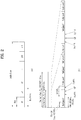
- FIG. 1 illustrates physical channels used in 3GPP LTE(-A) and a signal transmission method using the same.
- the UE When powered on or when a UE initially enters a cell, the UE performs initial cell search involving synchronization with a BS in step S101.
- the UE synchronizes with the BS and acquire information such as a cell Identifier (ID) by receiving a primary synchronization channel (P-SCH) and a secondary synchronization channel (S-SCH) from the BS.
- the UE may receive broadcast information from the cell on a physical broadcast channel (PBCH).
- PBCH physical broadcast channel
- the UE may check a downlink channel status by receiving a downlink reference signal (DL RS) during initial cell search.
- DL RS downlink reference signal
- the UE may acquire more specific system information by receiving a physical downlink control channel (PDCCH) and receiving a physical downlink shared channel (PDSCH) based on information of the PDCCH in step S102.
- a physical downlink control channel (PDCCH)
- PDSCH physical downlink shared channel
- the UE may perform a random access procedure to access the BS in steps S103 to S106.
- the UE may transmit a preamble to the BS on a physical random access channel (PRACH) (S103) and receive a response message for preamble on a PDCCH and a PDSCH corresponding to the PDCCH (S104).
- PRACH physical random access channel
- the UE may perform a contention resolution procedure by further transmitting the PRACH (S105) and receiving a PDCCH and a PDSCH corresponding to the PDCCH (S106).
- the UE may receive a PDCCH/PDSCH (S107) and transmit a physical uplink shared channel (PUSCH)/physical uplink control channel (PUCCH) (S108), as a general downlink/uplink signal transmission procedure.
- Control information transmitted from the UE to the BS is referred to as uplink control information (UCI).
- the UCI includes hybrid automatic repeat and request acknowledgement/negative-acknowledgement (HARQ-ACK/NACK), scheduling request (SR), channel state information (CSI), etc.
- the CSI includes a channel quality indicator (CQI), a precoding matrix indicator (PMI), a rank indicator (RI), etc.
- the UCI While the UCI is transmitted on a PUCCH in general, the UCI may be transmitted on a PUSCH when control information and traffic data need to be simultaneously transmitted. In addition, the UCI may be aperiodically transmitted through a PUSCH according to request/command of a network.
- FIG. 2 illustrates a radio frame structure. Uplink/downlink data packet transmission is performed on a subframe-by-subframe basis. A subframe is defined as a predetermined time interval including a plurality of symbols.
- 3GPP LTE supports a type-1 radio frame structure applicable to frequency division duplex (FDD) and a type-2 radio frame structure applicable to time division duplex (TDD).
- FDD frequency division duplex
- TDD time division duplex
- FIG. 2(a) illustrates a type-1 radio frame structure.
- a downlink subframe includes 10 subframes each of which includes 2 slots in the time domain.
- a time for transmitting a subframe is defined as a transmission time interval (TTI).
- TTI transmission time interval
- each subframe has a duration of 1ms and each slot has a duration of 0.5ms.
- a slot includes a plurality of OFDM symbols in the time domain and includes a plurality of resource blocks (RBs) in the frequency domain. Since downlink uses OFDM in 3GPP LTE, an OFDM symbol represents a symbol period. The OFDM symbol may be called an SC-FDMA symbol or symbol period.
- An RB as a resource allocation unit may include a plurality of consecutive subcarriers in one slot.
- the number of OFDM symbols included in one slot may depend on cyclic prefix (CP) configuration.
- CPs include an extended CP and a normal CP.
- the number of OFDM symbols included in one slot may be 7.
- the length of one OFDM symbol increases, and thus the number of OFDM symbols included in one slot is smaller than that in case of the normal CP.
- the number of OFDM symbols allocated to one slot may be 6.
- the extended CP can be used to reduce inter-symbol interference.
- one subframe When the normal CP is used, one subframe includes 14 OFDM symbols since one slot has 7 OFDM symbols. The first three OFDM symbols at most in each subframe can be allocated to a PDCCH and the remaining OFDM symbols can be allocated to a PDSCH.
- FIG. 2(b) illustrates a type-2 radio frame structure.
- the type-2 radio frame includes 2 half frames. Each half frame includes 4(5) normal subframes and 10 special subframes. The normal subframes are used for uplink or downlink according to UL-DL configuration. A subframe is composed of 2 slots.
- Table 1 shows subframe configurations in a radio frame according to UL-DL configurations.
- Uplink-downlink configuration Downlink-to-Uplink Switch point periodicity
- Subframe number 0 1 2 3 4 5 6 7 8 9 0 5ms D S U U U D S U U U 1 5ms D S U U D D S U U D 2 5ms D S U D D D S U D D 3 10ms D S U U U D D D D D D 4 10ms D S U U D D D D D D 5 10ms D S U D D D D D D D 6 5ms D S U U U U D S U U D S U U D S U U D
- D denotes a downlink subframe
- U denotes an uplink subframe
- S denotes a special subframe.
- the special subframe includes DwPTS (Downlink Pilot TimeSlot), GP (Guard Period), and UpPTS (Uplink Pilot TimeSlot).
- DwPTS is used for initial cell search, synchronization or channel estimation in a UE
- UpPTS is used for channel estimation in a BS and uplink transmission synchronization in a UE.
- the GP eliminates UL interference caused by multi-path delay of a DL signal between a UL and a DL.
- the radio frame structure is merely exemplary and the number of subframes included in the radio frame, the number of slots included in a subframe, and the number of symbols included in a slot can be vary.
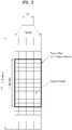
- FIG. 3 illustrates a resource grid of a downlink slot.
- a downlink slot includes a plurality of OFDM symbols in the time domain. While one downlink slot may include 7 OFDM symbols and one resource block (RB) may include 12 subcarriers in the frequency domain in the figure, the present disclosure is not limited thereto.
- Each element on the resource grid is referred to as a resource element (RE).
- One RB includes 12 ⁇ 7 REs.
- the number NRB of RBs included in the downlink slot depends on a downlink transmit bandwidth.
- the structure of an uplink slot may be same as that of the downlink slot.
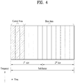
- FIG. 4 illustrates a downlink subframe structure
- a maximum of three (four) OFDM symbols located in a front portion of a first slot within a subframe correspond to a control region to which a control channel is allocated.
- the remaining OFDM symbols correspond to a data region to which a physical downlink shared chancel (PDSCH) is allocated.
- a basic resource unit of the data region is an RB.
- Examples of downlink control channels used in LTE include a physical control format indicator channel (PCFICH), a physical downlink control channel (PDCCH), a physical hybrid ARQ indicator channel (PHICH), etc.
- the PCFICH is transmitted at a first OFDM symbol of a subframe and carries information regarding the number of OFDM symbols used for transmission of control channels within the subframe.
- the PHICH is a response of uplink transmission and carries a HARQ acknowledgment (ACK)/negative-acknowledgment (NACK) signal.
- Control information transmitted through the PDCCH is referred to as downlink control information (DCI).
- the DCI includes uplink or downlink scheduling information or an uplink transmit power control command for an arbitrary UE group.
- DCI downlink control information
- Formats 0, 3, 3A and 4 for uplink and formats 1, 1A, 1B, 1C, 1D, 2, 2A, 2B and 2C for downlink are defined as DCI formats.
- Information field type, the number of information fields, the number of bits of each information field, etc. depend on DIC format.
- the DCI formats selectively include information such as hopping flag, RB assignment, MCS (Modulation Coding Scheme), RV (Redundancy Version), NDI (New Data Indicator), TPC (Transmit Power Control), HARQ process number, PMI (Precoding Matrix Indicator) confirmation as necessary.
- control information matched to a DCI format depends on the DCI format.
- An arbitrary DCI format may be used to transmit two or more types of control information.
- DIC formats 0/1A is used to carry DCI format 0 or DIC format 1, which are discriminated from each other using a flag field.
- a PDCCH may carry a transport format and a resource allocation of a downlink shared channel (DL-SCH), resource allocation information of an uplink shared channel (UL-SCH), paging information on a paging channel (PCH), system information on the DL-SCH, information on resource allocation of an upper-layer control message such as a random access response transmitted on the PDSCH, a set of Tx power control commands on individual UEs within an arbitrary UE group, a Tx power control command, information on activation of a voice over IP (VoIP), etc.
- a plurality of PDCCHs can be transmitted within a control region. The UE can monitor the plurality of PDCCHs.
- the PDCCH is transmitted on an aggregation of one or several consecutive control channel elements (CCEs).
- the CCE is a logical allocation unit used to provide the PDCCH with a coding rate based on a state of a radio channel.
- the CCE corresponds to a plurality of resource element groups (REGs).
- a format of the PDCCH and the number of bits of the available PDCCH are determined by the number of CCEs.
- the BS determines a PDCCH format according to DCI to be transmitted to the UE, and attaches a cyclic redundancy check (CRC) to control information.
- CRC cyclic redundancy check
- the CRC is masked with a unique identifier (referred to as a radio network temporary identifier (RNTI)) according to an owner or usage of the PDCCH.
- RNTI radio network temporary identifier
- a unique identifier e.g., cell-RNTI (C-RNTI)
- C-RNTI cell-RNTI
- P-RNTI paging-RNTI
- a system information RNTI (SI-RNTI) may be masked to the CRC.
- SI-RNTI system information RNTI
- RA-RNTI random access-RNTI
- the PDCCH carries a message known as DCI which includes resource assignment information and other control information for a UE or UE group.
- DCI resource assignment information
- a plurality of PDCCHs can be transmitted in a subframe.
- Each PDCCH is transmitted using one or more CCEs.
- Each CCE corresponds to 9 sets of 4 REs.
- the 4 REs are referred to as an REG.
- 4 QPSK symbols are mapped to one REG.
- REs allocated to a reference signal are not included in an REG, and thus the total number of REGs in OFDM symbols depends on presence or absence of a cell-specific reference signal.
- the concept of REG i.e. group based mapping, each group including 4 REs
- PCFICH and PHICH downlink control channels
- REG is used as a basic resource unit of a control region.
- 4 PDCCH formats are supported as shown in Table 2.
- Table 2 PDCCH format Number of CCEs (n) Number of REGs Number of PDCCH bits 0 1 9 72 1 2 8 144 2 4 36 288 3 5 72 576
- CCEs are sequentially numbered.
- transmission of a PDCCH having a format including n CCEs can be started using as many CCEs as a multiple of n.
- the number of CCEs used to transmit a specific PDCCH is determined by a BS according to channel condition. For example, if a PDCCH is for a UE having a high-quality downlink channel (e.g. a channel close to the BS), only one CCE can be used for PDCCH transmission. However, for a UE having a poor channel (e.g. a channel close to a cell edge), 8 CCEs can be used for PDCCH transmission in order to obtain sufficient robustness.
- a power level of the PDCCH can be controlled according to channel condition.
- LTE defines CCE positions in a limited set in which PDCCHs can be positioned for each UE.
- CCE positions in a limited set that the UE needs to monitor in order to detect the PDCCH allocated thereto may be referred to as a search space (SS).
- the SS has a size depending on PDCCH format.
- a UE-specific search space (USS) and a common search space (CSS) are separately defined.
- USS is set per UE and the range of the CSS is signaled to all UEs.
- the USS and the CSS may overlap for a given UE. In the case of a considerably small SS with respect to a specific UE, when some CCEs positions are allocated in the SS, remaining CCEs are not present.
- the BS may not find CCE resources on which PDCCHs will be transmitted to available UEs within given subframes. To minimize the possibility that this blocking continues to the next subframe, a UE-specific hopping sequence is applied to the starting point of the USS.
- Table 3 shows sizes of the CSS and USS.
- PDCCH format Number of CCEs (n) Number of candidates in common search space Number of candidates in dedicated search space 0 1 - 6 1 2 - 6 2 4 4 2 3 8 2 2
- the UE is not required to simultaneously search for all defined DCI formats.
- the UE searches for formats 0 and 1A at all times in the USS. Formats 0 and 1A have the same size and are discriminated from each other by a flag in a message.
- the UE may need to receive an additional format (e.g. format 1, 1B or 2 according to PDSCH transmission mode set by a BS).
- the UE searches for formats 1A and 1C in the CSS.
- the UE may be set to search for format 3 or 3A.
- Formats 3 and 3A have the same size as that of formats 0 and 1A and may be discriminated from each other by scrambling CRC with different (common) identifiers rather than a UE-specific identifier.
- PDSCH transmission schemes and information content of DCI formats according to transmission mode (TM) are arranged below.
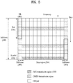
- FIG. 5 illustrates a structure of an uplink subframe used in LTE(-A).
- a subframe 500 is composed of two 0.5 ms slots 501. Assuming a length of a normal cyclic prefix (CP), each slot is composed of 7 symbols 502 and one symbol corresponds to one SC-FDMA symbol.
- a resource block (RB) 503 is a resource allocation unit corresponding to 12 subcarriers in the frequency domain and one slot in the time domain.
- the structure of the uplink subframe of LTE(-A) is largely divided into a data region 504 and a control region 505.
- a data region refers to a communication resource used for transmission of data such as voice, a packet, etc. transmitted to each UE and includes a physical uplink shared channel (PUSCH).
- PUSCH physical uplink shared channel
- a control region refers to a communication resource for transmission of an uplink control signal, for example, downlink channel quality report from each UE, reception ACK/NACK for a downlink signal, uplink scheduling request, etc. and includes a physical uplink control channel (PUCCH).
- a sounding reference signal (SRS) is transmitted through an SC-FDMA symbol that is lastly positioned in the time axis in one subframe. SRSs of a plurality of UEs, which are transmitted to the last SC-FDMAs of the same subframe, can be differentiated according to frequency positions/sequences.
- the SRS is used to transmit an uplink channel state to an eNB and is periodically transmitted according to a subframe period/offset set by a higher layer (e.g., RRC layer) or aperiodically transmitted at the request of the eNB.
- a higher layer e.g., RRC layer
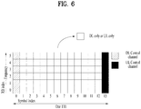
- FIG. 6 illustrates an exemplary self-contained subframe structure.
- the hatched area represents a DL control region
- the black area represents a UL control region.
- the area having no marks may be used for either DL data transmission or UL data transmission.
- DL transmission and UL transmission are sequentially performed in one subframe to transmit DL data and receive a UL ACK/NACK for the DL data in the subframe.
- the resulting reduction of a time taken to retransmit data when a data transmission error occurs may lead to minimization of the latency of a final data transmission.
- At least the following four subframe types may be considered as exemplary self-contained subframe types. Periods are enumerated in time order.
- a PDFICH, a PHICH, and a PDCCH may be transmitted in the DL control period, and a PDSCH may be transmitted in the DL data period.
- a PUCCH may be transmitted in the UL control period, and a PUSCH may be transmitted in the UL data period.
- the GP provides a time gap for switching from a transmission mode to a reception mode or from the reception mode to the transmission mode at an eNB and a UE. Some OFDM symbol(s) at a DL-to-UL switching time may be configured as the GP.
- different OFDM numerologies for example, different subcarrier spacings (SCSs) and hence different OFDM symbol (OS) durations may be configured between a plurality of cells aggregated for one UE.
- the (absolute time) duration of a time resource e.g., SF, slot or TTI
- a time unit referred to as a time unit (TU) for convenience
- symbol may cover OFDM symbol and SC-FDMA symbol.
- FIG. 7 illustrates a frame structure for 3GPP NR.
- 3GPP NR one radio frame includes 10 subframes each being 1ms in duration, like a radio frame in LTE/LTE-A (see FIG. 2 ).
- One subframe includes one or more slots and the length of a slot varies with an SCS.
- 3GPP NR supports SCSs of 15KHz, 30KHz, 60KHz, 120KHz, and 240KHz.
- a slot corresponds to a TTI of FIG. 6 .
- NB-IoT narrowband Internet of things
- NB-IoT supports three operation modes: in-band mode, guard-band mode, and stand-alone mode. The same requirements apply to each mode.
- An NB-IoT UE searches for an anchor carrier in units of 100kHz, for initial synchronization, and the center frequency of the anchor carrier should be located within ⁇ 7.5kHz from a 100-kHz channel raster in the in-band and guard-band. Further, the center 6 physical resource blocks (PRBs) of the LTE PRBs are not allocated to NB-IoT. Therefore, the anchor carrier may be located only in a specific PRB.
- PRBs physical resource blocks
- FIG. 8 is a diagram illustrating arrangement of an in-band anchor carrier in an LTE bandwidth of 10MHz.
- a direct current (DC) subcarrier is located on a channel raster. Since the center frequency spacing between adjacent PRBs is 180kHz, the center frequencies of PRBs 4, 9, 14, 19, 30, 35, 40 and 45 are located at ⁇ 2.5kHz from the channel raster. When the bandwidth is 20MHz, the center frequency of a PRB suitable for transmission on the anchor carrier is located at ⁇ 2.5kHz from the channel raster, and when the bandwidth is 3MHz, 5MHz, or 15MHz, the center frequency of a PRB suitable for transmission on the anchor carrier is located at ⁇ 7.5kHz from the channel raster.
- DC direct current
- the center frequency of a PRB immediately adjacent to an edge PRB of the LTE system is located at ⁇ 2.5kHz from the channel raster.
- a guard frequency band corresponding to three subcarriers from an edge PRB is used, and thus the center frequency of the anchor carrier may be located at ⁇ 7.5kHz from the channel raster.
- an anchor carrier is aligned with the 100-kHz channel raster, and all GSM carriers including the DC carrier may be available as NB-IoT anchor carriers.
- NB-IoT may support multiple carriers, and a combination of in-band and in-band, a combination of in-band and guard-band, a combination of guard-band and guard-band, and a combination of stand-alone and stand-alone are available.
- NB-IoT DL uses OFDMA with a 15-kHz SCS.
- OFDMA provides orthogonality between subcarriers, so that the NB-IoT system and the LTE system may coexist smoothly.
- NB-IoT DL For NB-IoT DL, physical channels such as a narrowband physical broadcast channel (NPBCH), a narrowband physical downlink shared channel (NPDSCH), and a narrowband physical downlink control channel (NPDCCH) may be provided, and physical signals such as a narrowband primary synchronization signal (NPSS), a narrowband primary synchronization signal (NSSS), and a narrowband reference signal (NRS) are provided.
- NPBCH narrowband physical broadcast channel
- NPDSCH narrowband physical downlink shared channel
- NPDCCH narrowband physical downlink control channel
- NPSS narrowband primary synchronization signal
- NSSS narrowband primary synchronization signal
- NSS narrowband reference signal
- the NPBCH delivers minimum system information required for an NB-IoT UE to access the system, a master information block-narrowband (MIB-NB) to the NB-IoT UE.
- the NPBCH may be transmitted repeatedly eight times in total for coverage enhancement.
- the transport block size (TBS) of the MIB-NB is 34 bits and updated every TTI of 640ms.
- the MIB-NB includes information about an operation mode, a system frame number (SFN), a hyper-SFN, the number of cell-specific reference signal (CRS) ports, and a channel raster offset.
- the NPSS is composed of a Zadoff-Chu (ZC) sequence of length 11 and a root index of 5.
- the NPSS may be generated by the following equation.
- S(1) for symbol index 1 may be defined as illustrated in Table 5.
- the NSSS is composed of a combination of a ZC sequence of length 131 and a binary scrambling sequence such as a Hadamard sequence.
- the NSSS indicates a PCID to NB-IoT UEs within the cell by the combination of sequences.
- a binary sequence b q (m) may be defined as illustrated in Table 6, and b 0 (m) to b 3 (m) represent columns 1, 32, 64, and 128 of a Hadamard matrix of order 128.
- Equation 4 nf represents a radio frame number and mod represents a modulo function.
- the NRS which is a reference signal for channel estimation required for demodulation of a DL physical channel, is generated in the same manner as in LTE. However, the NRS uses a narrowband-physical cell ID (NB-PCID) (or NCell ID or NB-IoT BS ID) as an initial value for initialization.
- NB-PCID narrowband-physical cell ID
- NCell ID or NB-IoT BS ID an initial value for initialization.
- the NPDCCH has the same transmission antenna configuration as the NPBCH, and delivers DCI.
- the NPDCCH supports three types of DCI formats.
- DCI format NO includes scheduling information about a narrowband physical uplink shared channel (NPUSCH), and DCI formats N1 and N2 includes NPDSCH scheduling information.
- the NPDCCH may be transmitted repeatedly up to 2048 times, for coverage enhancement.
- the NPDSCH is used to transmit data of a transport channel such as a DL-SCH or a paging channel (PCH).
- the NPDSCH has a maximum TBS of 680 bits and may be transmitted repeatedly up to 2048 times, for coverage enhancement.
- FIG. 9 is a diagram illustrating positions where narrowband NB-IoT physical DL channels/signals are transmitted in an FDD LTE system.
- the NPBCH is transmitted in the first subframe of each radio frame, the NPSS is transmitted in the sixth subframe of each radio frame, and the NSSS is transmitted in the last subframe of each even-numbered frame.
- An NB-IoT UE acquires frequency synchronization, symbol synchronization, and frame synchronization and searches 504 PCIDs (i.e., BS IDs) by synchronization signals (NPSS and NSSS).
- PCIDs i.e., BS IDs
- NPSS and NSSS synchronization signals
- the LTS synchronization signals are transmitted in 6 PRBs, whereas the NB-IoT synchronization signals are transmitted in one PRB.
- UL physical channels include a narrowband physical random access channel (NPRACH) and an NPUSCH, and support single-tone transmission and multi-tone transmission.
- Multi-tone transmission is supported only for an SCS of 15kHz, and single-tone transmission is supported for SCSs of 3.5kHz and 15kHz.
- SCS single-tone transmission
- SCSs 3.5kHz and 15kHz.
- the SCS when the SCS is 15kHz, orthogonality with the LTE system is maintained, thereby providing optimum performance.
- the 3.75-kHz SCS may destroy the orthogonality, resulting in performance degradation due to interference.
- An NPRACH preamble includes four symbol groups, each including a CP and five (SC-FDMA) symbols.
- the NPRACH supports only single-tone transmission with the 3.75-kHz SCS and provides CPs of 66.7 ⁇ s and 266.67 ⁇ s in length to support different cell radiuses.
- Each symbol group is subjected to frequency hopping in the following hopping pattern.
- Subcarriers carrying the first symbol group are determined pseudo-randomly.
- the second symbol group hops by one subcarrier, the third symbol group hops by six subcarriers, and the fourth symbol group hops by one subcarrier.
- the frequency hopping procedure is repeatedly applied.
- the NPRACH preamble may be repeatedly transmitted up to 128 times.
- the NPUSCH supports two formats. NPUSCH format 1 is used for UL-SCH transmission and has a maximum TBS of 1000 bits. NPUSCH format 2 is used for UCI transmission such as HARQ-ACK signaling. NPUSCH format 1 supports single-tone transmission and multi-tone transmission, whereas NPUSCH format 2 supports only single-tone transmission. In single-tone transmission, p/2-binary phase shift keying (BPSK) and p/4-quadrature phase shift keying (QPSK) may be used to reduce a peak-to-average power ratio (PAPR).
- BPSK phase shift keying
- QPSK p/4-quadrature phase shift keying
- all resources of one PRB may be allocated to NB-IoT.
- resource mapping in the in-band mode for co-existence with a legacy LTE signal. For example, resources (OFDM symbols 0 to 2 in each subframe) classified as a region allocated for LTE control channels may not be allocated to the NPSS and NSSS, and NPSS and NSSS symbols mapped to LTE CRS REs are punctured.
- FIG. 10 is a diagram illustrating resource allocation to an NB-IoT signal and an LTE signal in the in-band mode.
- the NPSS and NSSS are not transmitted in OFDM symbols corresponding to the control region of the legacy LTE system (the first three OFDM symbols of a subframe) regardless of an operation mode.
- NPSS/NSS REs colliding with LTE CRS REs in physical resources are punctured, for mapping without affecting the legacy LTE system.
- the NB-IoT UE may acquire information about the number of CRS antenna ports. However, the NB-IoT UE still may not acquire information about the LTE control channel allocation region. Therefore, the NPDSCH carrying system information block type 1 (SIB1) data is not mapped to resources classified as the LTE control channel allocation region.
- SIB1 system information block type 1
- REs which are not allocated to the LTE CRS may be allocated to the NPDSCH. Since the NB-IoT UE has acquired all information related to resource mapping after receiving SIB1, an eNB may map the NPDSCH (except for the case where SIB1 is transmitted) and the NPDCCH to available resources based on LTE control channel information and the number of CRS antenna ports.
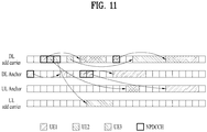
- FIG. 11 is a diagram illustrating an exemplary operation when multiple carriers are configured in FDD NB-IoT.
- a DL/UL anchor carrier is basically configured, and a DL (and UL) non-anchor carrier may be additionally configured.
- RRCConnectionReconfiguration may include information about the non-anchor carrier.
- a UE receives data only in the DL non-anchor carrier.
- synchronization signals NPSS and NSSS
- MIB and SIB broadcast signal
- a paging signal are provided only in the anchor carrier.
- the UE listens to only the DL non-anchor carrier while the UE is in an RRC_CONNECTED state. Similarly, when the UL non-anchor carrier is configured, the UE transmits data only in the UL non-anchor carrier, not being allowed to transmit data simultaneously in the UL non-anchor carrier and the UL anchor carrier. When the UE transitions to an RRC_IDLE state, the UE returns to the anchor carrier.
- UE1 is configured only with anchor carriers
- UE2 is configured additionally with a DL/UL non-anchor carrier
- UE3 is configured additionally with a DL non-anchor carrier. Accordingly, each UE transmits and receives data in the following carriers.
- - UE2 data reception (DL non-anchor carrier) and data transmission (UL non-anchor carrier)
- the NB-IoT UE is not capable of simultaneous transmission and reception, and a transmission/reception operation is limited to one band. Therefore, even though multiple carriers are configured, the UE requires only one transmission/reception chain in a 180-kHz band.
- the present disclosure largely proposes (1) a UL/DL interlaced scheduling method, (2) a DL early termination method, (3) a UL early termination method, and (4) a switching time securing method.
- the UL/DL interlaced scheduling method proposed in the present disclosure may be applied to a system supporting multiple repetitions of DL and UL transmissions/receptions. Particularly, the UL/DL interlaced scheduling method may be applied effectively, when DL and UL alternate during repeated transmissions/receptions. While the present disclosure is described in the context of an NB-IoT system conforming to 3GPP LTE Rel-13 and Rel-14, for the convenience of description, the description is also applicable to a system conforming to a subsequent release, a system requiring repeated transmissions as in eMTC, and other general systems.
- the present disclosure is effectively applicable to a case in which the amounts of DL and UL resources are different according to a UL/DL configuration as in TDD, the present disclosure may also be used, when DL resources and UL resources are not enough for repeated transmissions in a system operating in any other duplex mode.
- the NPDCCH may be replaced by the PDCCH or DL (physical) control channel
- the NPDSCH may be replaced by the PDSCH, DL (physical) shared channel, or DL (physical) data channel.
- the NPUSCH may be replaced by the PUSCH, UL (physical) shared channel, or UL (physical) data channel.
- DL and UL alternate with each other every predetermined period in the time domain (e.g., every 5ms or 10ms in LTE).
- DL resources which appear every predetermined period may be wasted in a system characterized by repeated transmissions in one HARQ process, like NB-IoT. Resources may also be wasted when a UL transmission is not allowed before a DL reception is completed.
- UL/DL interlaced scheduling methods are proposed, in which UL and DL alternate with each other, for transmission/reception.
- a UE To transmit UL data and receive DL data, a UE needs to receive a UL grant and a DL grant in DL resources (e.g., a DL subframe or slot).
- DL resources e.g., a DL subframe or slot.
- a system suffering from shortage of DL resources like a TDD system requires a method of including both a UL grant and a DL grant in one DCI, instead of independently transmitting the UL grant and the DL grant.
- a single DCI-based UL/DL scheduling method is proposed, and the DCI may need an additional field indicating "UL grant", "DL grant", or "UL/DL grant". The following may be considered.
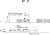
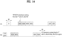
- FIGS. 12 , 13 and 14 illustrate exemplary signal transmissions according to Opt. 2.
- an SCH is an NPUSCH or NPDSCH according to resources (i.e., UL or DL resources), and a U/D grant (i.e., DL/UL joint DCI) schedules UL and DL by one NPDCCH.
- UL and DL may represent a UL carrier and a DL carrier, respectively, or UL resources (e.g., a UL subframe or slot) and DL resources (e.g., a DL subframe or slot) of the same carrier.
- the U/D grant may imply that UL scheduling information and DL scheduling information are delivered on an NPDCCH at time points which are not overlapped.
- k0 may be indicated by the U/D grant and used as both of the NPDSCH-to-ACK/NACK delay and the DCI-to-NPUSCH delay.
- A/N represents ACK/NACK information for DL-SCH data (e.g., TB).
- DL-SCH data may be transmitted on an NPDSCH
- UL-SCH data may be transmitted on an NPUSCH.
- Different hatching on UL and DL implies changing of a scrambling sequence and/or a redundancy version during repeated transmissions of a physical channel.
- an ACK/NACK for a DL-SCH may be piggybacked to NPUSCH format 1 ( FIGS. 12 and 13 ) or transmitted separately ( FIG. 14 ) according to the presence or absence of a subframe of NPUSCH format 1 after an NPDSCH-to-ACK/NACK delay (e.g., k0) from a reception time of the last subframe of the DL-SCH.
- FIG. 12 illustrates a case in which UL-SCH (e.g., NPUSCH) subframes and DL-SCH subframes end at similar time points, and FIG.
- FIG. 13 illustrates a case in which UL-SCH subframes exist after the last subframe of a DL-SCH.
- a DL grant may be monitored during transmission of the UL-SCH subframes.
- FIG. 14 illustrates a case in which there are no UL-SCH subframes after the last subframe of a DL-SCH.
- DL and UL subframes (slots) which alternate non-continuously on the time axis may be used effectively in UL/DL interlaced scheduling.
- UL/DL interlaced scheduling requires additional NPDCCH monitoring, resulting in consumption of more UE power.
- the UE may expect UL/DL interlaced scheduling or perform additional NPDCCH monitoring, only under a specific condition. For example, only when the number of DL subframes between UL repeated transmissions is less than a specific value (or ratio) or is equal to or less than a maximum repetition number of the NPDCCH, the UE may expect/perform additional NPDCCH monitoring.
- the UE may additionally monitor an NPDCCH in some time period, upon occurrence of a condition for postponing NPUSCH transmissions by the time period. This may be configured in consideration of a UL/DL switching gap of the UE. Further, a UL grant which has scheduled the NPUSCH may explicitly configure a specific time period during which an NPDCCH may be monitored during repeated NPUSCH transmissions.
- an eNB may set an NPDSCH repetition number to too large a value based on an inaccurate measurement received from a UE.
- the UE may succeed in decoding an NPDSCH before receiving the NPDSCH as many times as the configured repetition number.
- a method of reporting a DL ACK/NACK before repeated NPDSCH receptions are completed.
- a method of fast reporting an ACK/NACK in UL resources existing between DL repeated receptions may be applied effectively.
- the eNB may configure a plurality of DL ACK/NACK reporting resources.
- Each of the DL ACK/NACK reporting resources may correspond to an ACK/NACK reporting delay.
- the plurality of DL ACK/NACK reporting resources be denoted sequentially by 1 to N (N>1). Then, ACK/NACK resource 1 to ACK/NACK resource N-1 may be used only when the decoding result of the NPDSCH being received is an ACK.
- the UE may report an ACK or NACK in ACK/NACK resource N.
- ACK/NACK resource N corresponds to the longest ACK/NACK reporting delay. ⁇ Case in which an ACK occurs before DL repeated receptions are completed and a UL data transmission has been scheduled.
- the measurement accuracy of an NB-IoT system operating in a narrowband and supporting a large MCL is lower than that of a system using a wideband. Therefore, the eNB may set an NPUSCH repetition number to too large a value based on an inaccurate measurement received from the UE. Therefore, the eNB may succeed in decoding an NPUSCH before receiving the NPUSCH as many times as the configured repetition number. In this case, use of unnecessary UL resources may be reduced and unnecessary power consumption of the UE may be prevented, by fast feeding back an ACK for the UL data on DL.
- An ACK for a UL HARQ process may be transmitted in a DL subframe apart from an NPUSCH transmission time by a predetermined time interval.
- a NACK may not be transmitted separately.
- An ACK/NACK channel monitored during repeated NPUSCH transmissions, for UL early termination may be designed to be an explicit ACK channel (synchronous ACK/NACK).
- the explicit ACK channel may be designed to always carry an ACK report in DL resources/period placed in a specific relationship with NPUSCH transmission resources.
- the specific relationship may be established between resources (e.g., transmission time/frequency tones) of the explicit ACK channel and the starting subframe (or slot) and/or the positions/number of tones and/or a repetition number of NPUSCH format 1 carrying data for a UL HARQ process, and the resources for the explicit ACK channel may be reserved accordingly. Therefore, the UE may monitor an ACK for the UL HARQ process in specific preset DL resources during transmissions of NPUSCH format 1. When the UE fails in detecting the ACK, the UE may continue transmitting ongoing NPUSCH format 1.
- resources e.g., transmission time/frequency tones
- Method #8 Method of monitoring implicit ACK/NACK (DCI) during UL transmissions ]
- a transceiver switching time for DL-to-UL switching and UL-to-DL switching is required.
- a constraint may be imposed on use of the last period of a preceding (physical) channel and/or the starting period of a following (physical) channel in UL-to-DL or DL-to-UL interlaced transmission/reception.
- a method of securing a time gap is required.
- the method of securing a time gap may be applied differently according to an operation mode or the like.
- a time i.e., a time period in which a UE does not expect a DL signal reception or is not allowed to transmit a UL signal
- a basic unit time e.g., a subframe or slot
- various methods of configuring a channel of a time period in which a transmission is allowed or a reception may be expected within a basic time unit are available. For example, a signal in a time period used as a time gap may be ignored or a transmission/reception channel may be rate-matched differently in consideration of a time gap.
- Method #9 Method of securing a time gap for transceiver switching (DL-to-UL switching and UL-to-DL switching) between UL and DL interlaces]
- Interlaced scheduling and transmission/reception of interlaced channels may need a different time gap according to an operation mode.
- FIG. 15 is a diagram illustrating exemplary DL signal receptions according to the present disclosure.
- a UE may transmit a PUSCH repeatedly in a UL period (or duration).
- the UL period may include a plurality of time units (e.g., TTIs, subframes, or slots), and each PUSCH may be transmitted in a corresponding time unit of the UL period.
- the UE may then be scheduled to repeatedly receive a PDSCH in a DL period (or duration) immediately after the repeated PUSCH transmissions.
- the DL period may also include a plurality of time units (e.g., TTIs, subframes, or slots), and each PDSCH may be transmitted in a corresponding time unit of the DL period.
- the UE may start to receive each PDSCH in an OFDM symbol after a k th OFDM symbol in a corresponding time unit of the DL period.
- k is an integer larger than 1 and may be received in system information (SI) (e.g., an NB-IoT SIB).
- SI system information
- the UE may skip a signal reception (operation) at the start of the DL period during repeated PDSCH receptions. For example, for the first (1 st ) PDSCH, a signal reception (operation) may be skipped in at least part of the first OFDM symbol of a corresponding time unit. Reception of each of the second and subsequent PDSCHs may start in the first (1 st ) symbol of a corresponding time unit.
- the repeated PUSCH transmissions and the repeated PDSCH receptions may be performed in TDM in the same carrier.
- a UL/DL resource configuration for the carrier may be indicated by a UL/DL configuration listed in Table 1.
- the PUSCH may include the NPUSCH
- the PDSCH may include the NPDSCH.
- An SCS used for the (N)PDSCH transmissions may be 15kHz.
- the wireless communication system may include a 3GPP-based wireless communication system. ⁇
- a guard time period e.g., subframe, slot, symbol(s), part of a symbol for transceiver switching may be punctured or rate-matched.
- Method #9 is not applied in a situation in which Method #10 is applied or npusch-AllSymbols and srs-SubframeConfig are configured to avoid an SRS transmission from a legacy LTE UE.
- Method #9 may not be applied.
- a DL valid subframe refers to a subframe available for an NPDCCH or NPDSCH transmission
- a UL valid subframe refers to a subframe available for an NPUSCH transmission. Accordingly, for example, in the illustrated case of FIG.
- skipping of transmission of (one or more) last symbols may be indicated/configured.
- the UE In the in-band operation mode, the UE operates in the manner illustrated in FIG. 15 .
- the UE In the guard-band/stand-along operation mode, the UE does not skip a signal reception (operation) at the start of the DL subframe immediately after the subframe carrying an NPUSCH. That is, the UE may start to receive the NPDSCH signal in the first (1 st ) symbol of the DL subframe shortly after the subframe carrying the NPUSCH.
- Method #10 Method of securing a time gap for transceiver switching (DL-to-UL switching and UL-to-DL switching) and/or an RF switching gap by using an SRS period configuration ]
- a method of securing a switching gap by configuring an SRS transmission period may be available.
- Method #9 a UE is not allowed to receive part of a DL signal after switching and transition.
- a time gap is secured by allowing/configuring a UE not to transmit part of a UL signal before switching.
- Table 7 illustrates an example of configuring npusch-AllSymbols and srs-SubframeConfig to avoid an SRS transmission from a legacy LTE UE.
- Table 7 When higher layer parameter npusch-AllSymbols is set to false, resource elements in SC-FDMA symbols overlapping with a symbol configured with SRS according to srs-SubframeConfig shall be counted in the NPUSCH mapping but not used for transmission of the NPUSCH.
- higher layer parameter npusch-AllSymbols is set to true, all symbols are transmitted
- srs-SubframeConfig indicates a subframe periodicity/offset used to define a subframe set configured with an SRS transmission.
- a UL-to-DL switching gap is secured, for example, by using only npusch-AllSymbols or its similar information without directly using srs-SubframeConfig.
- npusch-AllSymbols or a similar parameter, that is, a parameter indicating non-transmission of the last symbol of an NPUSCH, the last symbol of a successive UL valid subframe, or the last symbol of a UL valid subframe in a period in which the UL valid subframe is adjacent to a DL valid subframe
- the proposed interpretation/indication may be limited to the followings. The followings may be combined.
- the proposed interpretation/indication may be applied differently according to an NB-IoT operation mode. For example, because the control area of a subframe may be used for a UL-to-DL gap in the in-band operation mode, the operation of skipping transmission of a last UL symbol may not be performed. Therefore, the operation of skipping transmission of a last UL symbol may be performed only in the guard-band/stand-alone operation mode.
- Method #9 when Method #9 is applied, Method #10 may not be configured or the operation of Method #10 may be skipped.
- the proposed Method #9 and Method #10 may be used to secure a transceiver switching gap and, when an NB-IoT/eMTC relay is introduced, to mitigate interference between links/channels of a BS and a relay, a relay and a UE, and a relay and a relay. That is, when a relay communicates with 1) a BS, 2) a UE serviced by the relay, or 3) a relay at the next hop, by time division, time gaps may be required among the periods of 1), 2) and 3) and the proposed Method #9 and Method #10 may be used to secure the time gaps.
- the UL/DL interlaced scheduling method proposed in the present disclosure may correspond to a UE capability, for example, relate to the number of HARQ processes. That is, a UE supporting only single-HARQ may not expect interlaced scheduling. However, a throughput may be more improved by interlaced scheduling than by 2-HARQ, according to a UL/DL configuration in a TDD system. Therefore, the UE supporting only single-HARQ may also indicate support of interlaced scheduling by a separate capability signal. Further, interlaced scheduling may be supported in a manner satisfying a specific method or a specific condition in consideration of the complexity of a buffer/memory of the UE (when a soft buffer of a receiver and a soft-buffer of a transmitter are shared).
- the eNB may perform interlaced scheduling. For example, the eNB may perform interlaced scheduling such that an NPDSCH to be scheduled for a UE and an NPUSCH to be scheduled on UL do not exceed a specific memory size (e.g., a reference memory size set based on a single-HARQ buffer or a reference memory size set based on a 2-HARQ buffer, in consideration of the HARQ process capability of the UE).
- a specific memory size e.g., a reference memory size set based on a single-HARQ buffer or a reference memory size set based on a 2-HARQ buffer, in consideration of the HARQ process capability of the UE.
- the reception soft buffer of the UE may calculate the number of bits in which an LLR is represented per information bit by using a specific value indicated by the eNB or defined in the standards.
- FIG. 16 illustrates a BS and a UE of a wireless communication system, which are applicable to embodiments of the present disclosure.
- the wireless communication system includes a BS 110 and a UE 120.
- the wireless communication system includes a relay, the BS or UE may be replaced by the relay.
- the BS 110 includes a processor 112, a memory 114 and a radio frequency (RF) unit 116.
- the processor 112 may be configured to implement the procedures and/or methods proposed by the present disclosure.
- the memory 114 is connected to the processor 112 and stores information related to operations of the processor 112.
- the RF unit 116 is connected to the processor 112 and transmits and/or receives an RF signal.
- the UE 120 includes a processor 122, a memory 124 and an RF unit 126.
- the processor 122 may be configured to implement the procedures and/or methods proposed by the present disclosure.
- the memory 124 is connected to the processor 122 and stores information related to operations of the processor 122.
- the RF unit 126 is connected to the processor 122 and transmits and/or receives an RF signal.
- a description is made centering on a data transmission and reception relationship among a BS, a relay, and an MS.
- a specific operation described as performed by the BS may be performed by an upper node of the BS.
- various operations performed for communication with an MS may be performed by the BS, or network nodes other than the BS.
- the term 'BS' may be replaced with the term 'fixed station', 'Node B', 'enhanced Node B (eNode B or eNB)', 'access point', etc.
- the term 'UE' may be replaced with the term 'Mobile Station (MS)', 'Mobile Subscriber Station (MSS)', 'mobile terminal', etc.
- the embodiments of the present disclosure may be achieved by various means, for example, hardware, firmware, software, or a combination thereof.
- the methods according to the embodiments of the present disclosure may be achieved by one or more Application Specific Integrated Circuits (ASICs), Digital Signal Processors (DSPs), Digital Signal Processing Devices (DSPDs), Programmable Logic Devices (PLDs), Field Programmable Gate Arrays (FPGAs), processors, controllers, microcontrollers, microprocessors, etc.
- ASICs Application Specific Integrated Circuits
- DSPs Digital Signal Processors
- DSPDs Digital Signal Processing Devices
- PLDs Programmable Logic Devices
- FPGAs Field Programmable Gate Arrays
- processors controllers, microcontrollers, microprocessors, etc.
- the embodiments of the present disclosure may be implemented in the form of a module, a procedure, a function, etc.
- software code may be stored in a memory unit and executed by a processor.
- the memory unit is located at the interior or exterior of the processor and may transmit and receive data to and from the processor via various known means.
- the present disclosure is applicable to UEs, eNBs or other apparatuses of a wireless mobile communication system.
Landscapes
- Engineering & Computer Science (AREA)
- Signal Processing (AREA)
- Computer Networks & Wireless Communication (AREA)
- Quality & Reliability (AREA)
- Mobile Radio Communication Systems (AREA)
Applications Claiming Priority (8)
| Application Number | Priority Date | Filing Date | Title |
|---|---|---|---|
| US201762543928P | 2017-08-10 | 2017-08-10 | |
| US201762586208P | 2017-11-15 | 2017-11-15 | |
| US201762591137P | 2017-11-27 | 2017-11-27 | |
| US201862662204P | 2018-04-24 | 2018-04-24 | |
| KR20180050204 | 2018-04-30 | ||
| KR20180053607 | 2018-05-10 | ||
| KR20180056995 | 2018-05-18 | ||
| PCT/KR2018/009187 WO2019031921A1 (ko) | 2017-08-10 | 2018-08-10 | 무선 통신 시스템에서 무선 신호 송수신 방법 및 장치 |
Publications (3)
| Publication Number | Publication Date |
|---|---|
| EP3668236A1 true EP3668236A1 (de) | 2020-06-17 |
| EP3668236A4 EP3668236A4 (de) | 2020-09-02 |
| EP3668236B1 EP3668236B1 (de) | 2022-03-30 |
Family
ID=70001933
Family Applications (1)
| Application Number | Title | Priority Date | Filing Date |
|---|---|---|---|
| EP18843838.6A Active EP3668236B1 (de) | 2017-08-10 | 2018-08-10 | Verfahren und vorrichtung für drahtlose signalübertragung oder empfang in einem drahtlosen kommunikationssystem |
Country Status (5)
| Country | Link |
|---|---|
| US (2) | US10779272B2 (de) |
| EP (1) | EP3668236B1 (de) |
| JP (1) | JP6905636B2 (de) |
| KR (1) | KR102225951B1 (de) |
| CN (1) | CN111247862B (de) |
Families Citing this family (10)
| Publication number | Priority date | Publication date | Assignee | Title |
|---|---|---|---|---|
| WO2019004729A1 (ko) * | 2017-06-27 | 2019-01-03 | 엘지전자 주식회사 | 무선 통신 시스템에서 무선 신호 송수신 방법 및 장치 |
| CN110475371B (zh) * | 2018-05-09 | 2023-10-27 | 夏普株式会社 | 用户设备执行的方法、用户设备和基站 |
| EP3860281B1 (de) * | 2018-09-28 | 2025-12-03 | Ntt Docomo, Inc. | Sendevorrichtung und empfangsvorrichtung |
| US11432312B2 (en) * | 2019-04-26 | 2022-08-30 | Qualcomm Incorporated | Uplink scheduling techniques for enhanced feedback in wireless communications |
| US11937256B2 (en) * | 2020-04-14 | 2024-03-19 | Qualcomm Incorporated | Time gaps in multi-slot grants |
| CN115088309B (zh) * | 2021-01-14 | 2025-02-18 | 北京小米移动软件有限公司 | 信息传输方法、装置、通信设备和存储介质 |
| US11647509B2 (en) * | 2021-03-24 | 2023-05-09 | Qualcomm Incorporated | Gap between downlink control information and corresponding downlink and uplink communications |
| US12335961B2 (en) * | 2021-09-17 | 2025-06-17 | Qualcomm Incorporated | Resources for uplink control information multiplexing in an absence of demodulation reference signals |
| US20230147159A1 (en) * | 2021-11-11 | 2023-05-11 | Qualcomm Incorporated | Time gaps for segment-based uplink transmissions in non-terrestrial networks |
| WO2024024698A1 (ja) * | 2022-07-28 | 2024-02-01 | 日本電気株式会社 | 基地局、無線端末、通信システム、通信方法、及びプログラム |
Family Cites Families (14)
| Publication number | Priority date | Publication date | Assignee | Title |
|---|---|---|---|---|
| WO2008013339A1 (en) * | 2006-07-26 | 2008-01-31 | Electronics And Telecommunications Research Institute | Cell search method in ofdm cellular system, frame transmission method thereof, and forward link frame structure thereof |
| KR101560390B1 (ko) * | 2011-06-15 | 2015-10-13 | 엘지전자 주식회사 | 제어 정보를 전송하는 방법 및 이를 위한 장치 |
| KR101578012B1 (ko) * | 2011-07-28 | 2015-12-28 | 엘지전자 주식회사 | 무선 접속 시스템에서 하향링크 제어정보 송수신 방법 및 이를 위한 단말 |
| US9407393B2 (en) * | 2011-11-21 | 2016-08-02 | Lg Electronics Inc. | Method for receiving downlink data and wireless device using same |
| CN105493417B (zh) * | 2013-07-26 | 2018-11-09 | Lg 电子株式会社 | 发送用于mtc的信号的方法及其设备 |
| WO2017052319A1 (ko) * | 2015-09-24 | 2017-03-30 | 엘지전자 주식회사 | 무선 통신 시스템에서 임의 접속 신호를 송신하기 위한 방법 및 이를 위한 장치 |
| WO2017057943A1 (ko) * | 2015-09-30 | 2017-04-06 | 엘지전자(주) | 무선 통신 시스템에서 상향링크 신호를 전송하기 위한 방법 및 이를 위한 장치 |
| US10728078B2 (en) * | 2015-10-19 | 2020-07-28 | Lg Electronics Inc. | Method and user equipment for receiving downlink signal, and method and base station for transmitting downlink signal |
| TWI803947B (zh) * | 2015-11-04 | 2023-06-01 | 美商內數位專利控股公司 | 無線傳輸/接收單元及由其實施的方法 |
| US9853751B2 (en) * | 2015-12-21 | 2017-12-26 | Vecima Networks Inc. | Method of estimating the frequency response of multipath channels |
| CN113507354B (zh) * | 2016-01-11 | 2024-08-02 | 苹果公司 | 用于IoT控制信道的装置和方法 |
| CN107040358A (zh) * | 2016-02-04 | 2017-08-11 | 株式会社Kt | 用于NB‑IoT UE发送和接收上行信号的方法及其装置 |
| US10256957B2 (en) * | 2016-08-12 | 2019-04-09 | Innovative Technology Lab Co., Ltd. | Method and apparatus for transmitting/receiving positioning reference signal |
| US11272492B2 (en) * | 2017-08-10 | 2022-03-08 | Intel Corporation | TDD configuration and use of special subframes for feNB-IoTs |
-
2018
- 2018-08-10 EP EP18843838.6A patent/EP3668236B1/de active Active
- 2018-08-10 CN CN201880065397.9A patent/CN111247862B/zh active Active
- 2018-08-10 KR KR1020207006926A patent/KR102225951B1/ko active Active
- 2018-08-10 JP JP2020507574A patent/JP6905636B2/ja active Active
-
2020
- 2020-02-10 US US16/786,624 patent/US10779272B2/en active Active
- 2020-09-11 US US17/018,342 patent/US11356998B2/en active Active
Also Published As
| Publication number | Publication date |
|---|---|
| EP3668236A4 (de) | 2020-09-02 |
| US10779272B2 (en) | 2020-09-15 |
| US20200413384A1 (en) | 2020-12-31 |
| KR20200032231A (ko) | 2020-03-25 |
| US11356998B2 (en) | 2022-06-07 |
| KR102225951B1 (ko) | 2021-03-10 |
| EP3668236B1 (de) | 2022-03-30 |
| CN111247862A (zh) | 2020-06-05 |
| JP2020530243A (ja) | 2020-10-15 |
| CN111247862B (zh) | 2023-05-12 |
| JP6905636B2 (ja) | 2021-07-21 |
| US20200221433A1 (en) | 2020-07-09 |
Similar Documents
| Publication | Publication Date | Title |
|---|---|---|
| US11337050B2 (en) | Method and device for transreceiving discovery reference signal in wireless access system supporting unlicensed band | |
| US11546195B2 (en) | Method and device for transmitting discovery reference signal in wireless access system supporting unlicensed band | |
| US11356998B2 (en) | Method and device for wireless signal transmission or reception in wireless communication system | |
| US11398882B2 (en) | Early termination of repeated transmissions between terminal and base station in wireless communication system | |
| CN107580801B (zh) | 在支持未授权带的无线接入系统中基于harq-ack信息调整竞争窗口大小的方法和支持该方法的设备 | |
| EP3410798B1 (de) | Verfahren und vorrichtung zum senden und empfangen eines drahtlossignals in einem drahtloskommunikationssystem | |
| EP3176962B1 (de) | Verfahren und vorrichtung zur übertragung eines drahtlosen signals in einem drahtloskommunikationssystem | |
| CN112492613B (zh) | 在支持未授权带的无线接入系统中执行cca的方法及其装置 | |
| EP2706690B1 (de) | Verfahren zum senden/empfangen von daten in einem drahtlosen zugangssystem sowie basisstation dafür | |
| US10039121B2 (en) | Scheduling method for device-to-device communication and apparatus for same | |
| US11246151B2 (en) | Method and apparatus for transmitting or receiving wireless signal in wireless communication system | |
| US11184908B2 (en) | Method and device for transmitting/receiving radio signal in wireless communication system | |
| EP3402285A2 (de) | Verfahren und vorrichtung zum senden und empfangen eines drahtlossignals in einem drahtloskommunikationssystem | |
| EP3734925A1 (de) | Verfahren und vorrichtung zum senden/empfangen eines drahtlossignals in einem drahtloskommunikationssystem | |
| US9401794B2 (en) | Method and apparatus for acquiring control information in wireless communication system | |
| US11272529B2 (en) | Method and device for transmitting/receiving radio signal in wireless communication system | |
| KR20150013458A (ko) | 신호 송수신 방법 및 이를 위한 장치 | |
| US20140286275A1 (en) | Method and apparatus for acquiring control information in a wireless communication system | |
| EP3404859B1 (de) | Verfahren und vorrichtung zum senden/empfangen eines drahtlossignals in einem drahtloskommunikationssystem |
Legal Events
| Date | Code | Title | Description |
|---|---|---|---|
| STAA | Information on the status of an ep patent application or granted ep patent |
Free format text: STATUS: THE INTERNATIONAL PUBLICATION HAS BEEN MADE |
|
| PUAI | Public reference made under article 153(3) epc to a published international application that has entered the european phase |
Free format text: ORIGINAL CODE: 0009012 |
|
| STAA | Information on the status of an ep patent application or granted ep patent |
Free format text: STATUS: REQUEST FOR EXAMINATION WAS MADE |
|
| 17P | Request for examination filed |
Effective date: 20200309 |
|
| AK | Designated contracting states |
Kind code of ref document: A1 Designated state(s): AL AT BE BG CH CY CZ DE DK EE ES FI FR GB GR HR HU IE IS IT LI LT LU LV MC MK MT NL NO PL PT RO RS SE SI SK SM TR |
|
| AX | Request for extension of the european patent |
Extension state: BA ME |
|
| A4 | Supplementary search report drawn up and despatched |
Effective date: 20200804 |
|
| RIC1 | Information provided on ipc code assigned before grant |
Ipc: H04L 5/00 20060101ALI20200730BHEP Ipc: H04W 72/12 20090101AFI20200730BHEP Ipc: H04L 1/18 20060101ALI20200730BHEP |
|
| DAV | Request for validation of the european patent (deleted) | ||
| DAX | Request for extension of the european patent (deleted) | ||
| STAA | Information on the status of an ep patent application or granted ep patent |
Free format text: STATUS: EXAMINATION IS IN PROGRESS |
|
| 17Q | First examination report despatched |
Effective date: 20210517 |
|
| GRAP | Despatch of communication of intention to grant a patent |
Free format text: ORIGINAL CODE: EPIDOSNIGR1 |
|
| STAA | Information on the status of an ep patent application or granted ep patent |
Free format text: STATUS: GRANT OF PATENT IS INTENDED |
|
| INTG | Intention to grant announced |
Effective date: 20211028 |
|
| GRAS | Grant fee paid |
Free format text: ORIGINAL CODE: EPIDOSNIGR3 |
|
| GRAA | (expected) grant |
Free format text: ORIGINAL CODE: 0009210 |
|
| STAA | Information on the status of an ep patent application or granted ep patent |
Free format text: STATUS: THE PATENT HAS BEEN GRANTED |
|
| AK | Designated contracting states |
Kind code of ref document: B1 Designated state(s): AL AT BE BG CH CY CZ DE DK EE ES FI FR GB GR HR HU IE IS IT LI LT LU LV MC MK MT NL NO PL PT RO RS SE SI SK SM TR |
|
| REG | Reference to a national code |
Ref country code: GB Ref legal event code: FG4D |
|
| REG | Reference to a national code |
Ref country code: CH Ref legal event code: EP |
|
| REG | Reference to a national code |
Ref country code: AT Ref legal event code: REF Ref document number: 1480366 Country of ref document: AT Kind code of ref document: T Effective date: 20220415 |
|
| REG | Reference to a national code |
Ref country code: DE Ref legal event code: R096 Ref document number: 602018033140 Country of ref document: DE |
|
| REG | Reference to a national code |
Ref country code: IE Ref legal event code: FG4D |
|
| REG | Reference to a national code |
Ref country code: LT Ref legal event code: MG9D |
|
| PG25 | Lapsed in a contracting state [announced via postgrant information from national office to epo] |
Ref country code: SE Free format text: LAPSE BECAUSE OF FAILURE TO SUBMIT A TRANSLATION OF THE DESCRIPTION OR TO PAY THE FEE WITHIN THE PRESCRIBED TIME-LIMIT Effective date: 20220330 Ref country code: RS Free format text: LAPSE BECAUSE OF FAILURE TO SUBMIT A TRANSLATION OF THE DESCRIPTION OR TO PAY THE FEE WITHIN THE PRESCRIBED TIME-LIMIT Effective date: 20220330 Ref country code: NO Free format text: LAPSE BECAUSE OF FAILURE TO SUBMIT A TRANSLATION OF THE DESCRIPTION OR TO PAY THE FEE WITHIN THE PRESCRIBED TIME-LIMIT Effective date: 20220630 Ref country code: LT Free format text: LAPSE BECAUSE OF FAILURE TO SUBMIT A TRANSLATION OF THE DESCRIPTION OR TO PAY THE FEE WITHIN THE PRESCRIBED TIME-LIMIT Effective date: 20220330 Ref country code: HR Free format text: LAPSE BECAUSE OF FAILURE TO SUBMIT A TRANSLATION OF THE DESCRIPTION OR TO PAY THE FEE WITHIN THE PRESCRIBED TIME-LIMIT Effective date: 20220330 Ref country code: BG Free format text: LAPSE BECAUSE OF FAILURE TO SUBMIT A TRANSLATION OF THE DESCRIPTION OR TO PAY THE FEE WITHIN THE PRESCRIBED TIME-LIMIT Effective date: 20220630 |
|
| REG | Reference to a national code |
Ref country code: NL Ref legal event code: MP Effective date: 20220330 |
|
| REG | Reference to a national code |
Ref country code: AT Ref legal event code: MK05 Ref document number: 1480366 Country of ref document: AT Kind code of ref document: T Effective date: 20220330 |
|
| PG25 | Lapsed in a contracting state [announced via postgrant information from national office to epo] |
Ref country code: LV Free format text: LAPSE BECAUSE OF FAILURE TO SUBMIT A TRANSLATION OF THE DESCRIPTION OR TO PAY THE FEE WITHIN THE PRESCRIBED TIME-LIMIT Effective date: 20220330 Ref country code: GR Free format text: LAPSE BECAUSE OF FAILURE TO SUBMIT A TRANSLATION OF THE DESCRIPTION OR TO PAY THE FEE WITHIN THE PRESCRIBED TIME-LIMIT Effective date: 20220701 Ref country code: FI Free format text: LAPSE BECAUSE OF FAILURE TO SUBMIT A TRANSLATION OF THE DESCRIPTION OR TO PAY THE FEE WITHIN THE PRESCRIBED TIME-LIMIT Effective date: 20220330 |
|
| PG25 | Lapsed in a contracting state [announced via postgrant information from national office to epo] |
Ref country code: NL Free format text: LAPSE BECAUSE OF FAILURE TO SUBMIT A TRANSLATION OF THE DESCRIPTION OR TO PAY THE FEE WITHIN THE PRESCRIBED TIME-LIMIT Effective date: 20220330 |
|
| PG25 | Lapsed in a contracting state [announced via postgrant information from national office to epo] |
Ref country code: SM Free format text: LAPSE BECAUSE OF FAILURE TO SUBMIT A TRANSLATION OF THE DESCRIPTION OR TO PAY THE FEE WITHIN THE PRESCRIBED TIME-LIMIT Effective date: 20220330 Ref country code: SK Free format text: LAPSE BECAUSE OF FAILURE TO SUBMIT A TRANSLATION OF THE DESCRIPTION OR TO PAY THE FEE WITHIN THE PRESCRIBED TIME-LIMIT Effective date: 20220330 Ref country code: RO Free format text: LAPSE BECAUSE OF FAILURE TO SUBMIT A TRANSLATION OF THE DESCRIPTION OR TO PAY THE FEE WITHIN THE PRESCRIBED TIME-LIMIT Effective date: 20220330 Ref country code: PT Free format text: LAPSE BECAUSE OF FAILURE TO SUBMIT A TRANSLATION OF THE DESCRIPTION OR TO PAY THE FEE WITHIN THE PRESCRIBED TIME-LIMIT Effective date: 20220801 Ref country code: ES Free format text: LAPSE BECAUSE OF FAILURE TO SUBMIT A TRANSLATION OF THE DESCRIPTION OR TO PAY THE FEE WITHIN THE PRESCRIBED TIME-LIMIT Effective date: 20220330 Ref country code: EE Free format text: LAPSE BECAUSE OF FAILURE TO SUBMIT A TRANSLATION OF THE DESCRIPTION OR TO PAY THE FEE WITHIN THE PRESCRIBED TIME-LIMIT Effective date: 20220330 Ref country code: CZ Free format text: LAPSE BECAUSE OF FAILURE TO SUBMIT A TRANSLATION OF THE DESCRIPTION OR TO PAY THE FEE WITHIN THE PRESCRIBED TIME-LIMIT Effective date: 20220330 Ref country code: AT Free format text: LAPSE BECAUSE OF FAILURE TO SUBMIT A TRANSLATION OF THE DESCRIPTION OR TO PAY THE FEE WITHIN THE PRESCRIBED TIME-LIMIT Effective date: 20220330 |
|
| PG25 | Lapsed in a contracting state [announced via postgrant information from national office to epo] |
Ref country code: PL Free format text: LAPSE BECAUSE OF FAILURE TO SUBMIT A TRANSLATION OF THE DESCRIPTION OR TO PAY THE FEE WITHIN THE PRESCRIBED TIME-LIMIT Effective date: 20220330 Ref country code: IS Free format text: LAPSE BECAUSE OF FAILURE TO SUBMIT A TRANSLATION OF THE DESCRIPTION OR TO PAY THE FEE WITHIN THE PRESCRIBED TIME-LIMIT Effective date: 20220730 Ref country code: AL Free format text: LAPSE BECAUSE OF FAILURE TO SUBMIT A TRANSLATION OF THE DESCRIPTION OR TO PAY THE FEE WITHIN THE PRESCRIBED TIME-LIMIT Effective date: 20220330 |
|
| REG | Reference to a national code |
Ref country code: DE Ref legal event code: R097 Ref document number: 602018033140 Country of ref document: DE |
|
| PG25 | Lapsed in a contracting state [announced via postgrant information from national office to epo] |
Ref country code: DK Free format text: LAPSE BECAUSE OF FAILURE TO SUBMIT A TRANSLATION OF THE DESCRIPTION OR TO PAY THE FEE WITHIN THE PRESCRIBED TIME-LIMIT Effective date: 20220330 |
|
| PLBE | No opposition filed within time limit |
Free format text: ORIGINAL CODE: 0009261 |
|
| STAA | Information on the status of an ep patent application or granted ep patent |
Free format text: STATUS: NO OPPOSITION FILED WITHIN TIME LIMIT |
|
| 26N | No opposition filed |
Effective date: 20230103 |
|
| PG25 | Lapsed in a contracting state [announced via postgrant information from national office to epo] |
Ref country code: MC Free format text: LAPSE BECAUSE OF FAILURE TO SUBMIT A TRANSLATION OF THE DESCRIPTION OR TO PAY THE FEE WITHIN THE PRESCRIBED TIME-LIMIT Effective date: 20220330 |
|
| REG | Reference to a national code |
Ref country code: CH Ref legal event code: PL |
|
| GBPC | Gb: european patent ceased through non-payment of renewal fee |
Effective date: 20220810 |
|
| PG25 | Lapsed in a contracting state [announced via postgrant information from national office to epo] |
Ref country code: LU Free format text: LAPSE BECAUSE OF NON-PAYMENT OF DUE FEES Effective date: 20220810 Ref country code: LI Free format text: LAPSE BECAUSE OF NON-PAYMENT OF DUE FEES Effective date: 20220831 Ref country code: CH Free format text: LAPSE BECAUSE OF NON-PAYMENT OF DUE FEES Effective date: 20220831 |
|
| REG | Reference to a national code |
Ref country code: BE Ref legal event code: MM Effective date: 20220831 |
|
| PG25 | Lapsed in a contracting state [announced via postgrant information from national office to epo] |
Ref country code: SI Free format text: LAPSE BECAUSE OF FAILURE TO SUBMIT A TRANSLATION OF THE DESCRIPTION OR TO PAY THE FEE WITHIN THE PRESCRIBED TIME-LIMIT Effective date: 20220330 |
|
| P01 | Opt-out of the competence of the unified patent court (upc) registered |
Effective date: 20230527 |
|
| PG25 | Lapsed in a contracting state [announced via postgrant information from national office to epo] |
Ref country code: IE Free format text: LAPSE BECAUSE OF NON-PAYMENT OF DUE FEES Effective date: 20220810 |
|
| PG25 | Lapsed in a contracting state [announced via postgrant information from national office to epo] |
Ref country code: BE Free format text: LAPSE BECAUSE OF NON-PAYMENT OF DUE FEES Effective date: 20220831 |
|
| PG25 | Lapsed in a contracting state [announced via postgrant information from national office to epo] |
Ref country code: GB Free format text: LAPSE BECAUSE OF NON-PAYMENT OF DUE FEES Effective date: 20220810 |
|
| PG25 | Lapsed in a contracting state [announced via postgrant information from national office to epo] |
Ref country code: CY Free format text: LAPSE BECAUSE OF FAILURE TO SUBMIT A TRANSLATION OF THE DESCRIPTION OR TO PAY THE FEE WITHIN THE PRESCRIBED TIME-LIMIT Effective date: 20220330 |
|
| PG25 | Lapsed in a contracting state [announced via postgrant information from national office to epo] |
Ref country code: MK Free format text: LAPSE BECAUSE OF FAILURE TO SUBMIT A TRANSLATION OF THE DESCRIPTION OR TO PAY THE FEE WITHIN THE PRESCRIBED TIME-LIMIT Effective date: 20220330 Ref country code: HU Free format text: LAPSE BECAUSE OF FAILURE TO SUBMIT A TRANSLATION OF THE DESCRIPTION OR TO PAY THE FEE WITHIN THE PRESCRIBED TIME-LIMIT; INVALID AB INITIO Effective date: 20180810 |
|
| PG25 | Lapsed in a contracting state [announced via postgrant information from national office to epo] |
Ref country code: TR Free format text: LAPSE BECAUSE OF FAILURE TO SUBMIT A TRANSLATION OF THE DESCRIPTION OR TO PAY THE FEE WITHIN THE PRESCRIBED TIME-LIMIT Effective date: 20220330 |
|
| PG25 | Lapsed in a contracting state [announced via postgrant information from national office to epo] |
Ref country code: MT Free format text: LAPSE BECAUSE OF FAILURE TO SUBMIT A TRANSLATION OF THE DESCRIPTION OR TO PAY THE FEE WITHIN THE PRESCRIBED TIME-LIMIT Effective date: 20220330 |
|
| REG | Reference to a national code |
Ref country code: DE Ref legal event code: R082 Ref document number: 602018033140 Country of ref document: DE Representative=s name: PLASSERAUD IP GMBH, DE |
|
| PGFP | Annual fee paid to national office [announced via postgrant information from national office to epo] |
Ref country code: DE Payment date: 20250707 Year of fee payment: 8 |
|
| PGFP | Annual fee paid to national office [announced via postgrant information from national office to epo] |
Ref country code: IT Payment date: 20250710 Year of fee payment: 8 |
|
| PGFP | Annual fee paid to national office [announced via postgrant information from national office to epo] |
Ref country code: FR Payment date: 20250715 Year of fee payment: 8 |