EP3668273B1 - Induktionsheizungssystem zum formen eines thermoplastischen artikels und verfahren zum formen eines thermoplastischen artikels - Google Patents
Induktionsheizungssystem zum formen eines thermoplastischen artikels und verfahren zum formen eines thermoplastischen artikels Download PDFInfo
- Publication number
- EP3668273B1 EP3668273B1 EP19210031.1A EP19210031A EP3668273B1 EP 3668273 B1 EP3668273 B1 EP 3668273B1 EP 19210031 A EP19210031 A EP 19210031A EP 3668273 B1 EP3668273 B1 EP 3668273B1
- Authority
- EP
- European Patent Office
- Prior art keywords
- mold
- induction
- metallic susceptor
- armature
- heating system
- Prior art date
- Legal status (The legal status is an assumption and is not a legal conclusion. Google has not performed a legal analysis and makes no representation as to the accuracy of the status listed.)
- Active
Links
Images





Classifications
-
- H—ELECTRICITY
- H05—ELECTRIC TECHNIQUES NOT OTHERWISE PROVIDED FOR
- H05B—ELECTRIC HEATING; ELECTRIC LIGHT SOURCES NOT OTHERWISE PROVIDED FOR; CIRCUIT ARRANGEMENTS FOR ELECTRIC LIGHT SOURCES, IN GENERAL
- H05B6/00—Heating by electric, magnetic or electromagnetic fields
- H05B6/02—Induction heating
- H05B6/10—Induction heating apparatus, other than furnaces, for specific applications
- H05B6/105—Induction heating apparatus, other than furnaces, for specific applications using a susceptor
-
- B—PERFORMING OPERATIONS; TRANSPORTING
- B29—WORKING OF PLASTICS; WORKING OF SUBSTANCES IN A PLASTIC STATE IN GENERAL
- B29C—SHAPING OR JOINING OF PLASTICS; SHAPING OF MATERIAL IN A PLASTIC STATE, NOT OTHERWISE PROVIDED FOR; AFTER-TREATMENT OF THE SHAPED PRODUCTS, e.g. REPAIRING
- B29C33/00—Moulds or cores; Details thereof or accessories therefor
- B29C33/02—Moulds or cores; Details thereof or accessories therefor with incorporated heating or cooling means
- B29C33/06—Moulds or cores; Details thereof or accessories therefor with incorporated heating or cooling means using radiation, e.g. electro-magnetic waves, induction heating
-
- H—ELECTRICITY
- H05—ELECTRIC TECHNIQUES NOT OTHERWISE PROVIDED FOR
- H05B—ELECTRIC HEATING; ELECTRIC LIGHT SOURCES NOT OTHERWISE PROVIDED FOR; CIRCUIT ARRANGEMENTS FOR ELECTRIC LIGHT SOURCES, IN GENERAL
- H05B6/00—Heating by electric, magnetic or electromagnetic fields
- H05B6/02—Induction heating
- H05B6/06—Control, e.g. of temperature, of power
-
- H—ELECTRICITY
- H05—ELECTRIC TECHNIQUES NOT OTHERWISE PROVIDED FOR
- H05B—ELECTRIC HEATING; ELECTRIC LIGHT SOURCES NOT OTHERWISE PROVIDED FOR; CIRCUIT ARRANGEMENTS FOR ELECTRIC LIGHT SOURCES, IN GENERAL
- H05B6/00—Heating by electric, magnetic or electromagnetic fields
- H05B6/02—Induction heating
- H05B6/36—Coil arrangements
- H05B6/38—Coil arrangements specially adapted for fitting into hollow spaces of workpieces
-
- H—ELECTRICITY
- H05—ELECTRIC TECHNIQUES NOT OTHERWISE PROVIDED FOR
- H05B—ELECTRIC HEATING; ELECTRIC LIGHT SOURCES NOT OTHERWISE PROVIDED FOR; CIRCUIT ARRANGEMENTS FOR ELECTRIC LIGHT SOURCES, IN GENERAL
- H05B6/00—Heating by electric, magnetic or electromagnetic fields
- H05B6/02—Induction heating
- H05B6/36—Coil arrangements
- H05B6/42—Cooling of coils
-
- H—ELECTRICITY
- H05—ELECTRIC TECHNIQUES NOT OTHERWISE PROVIDED FOR
- H05B—ELECTRIC HEATING; ELECTRIC LIGHT SOURCES NOT OTHERWISE PROVIDED FOR; CIRCUIT ARRANGEMENTS FOR ELECTRIC LIGHT SOURCES, IN GENERAL
- H05B6/00—Heating by electric, magnetic or electromagnetic fields
- H05B6/02—Induction heating
- H05B6/36—Coil arrangements
- H05B6/44—Coil arrangements having more than one coil or coil segment
-
- B—PERFORMING OPERATIONS; TRANSPORTING
- B29—WORKING OF PLASTICS; WORKING OF SUBSTANCES IN A PLASTIC STATE IN GENERAL
- B29C—SHAPING OR JOINING OF PLASTICS; SHAPING OF MATERIAL IN A PLASTIC STATE, NOT OTHERWISE PROVIDED FOR; AFTER-TREATMENT OF THE SHAPED PRODUCTS, e.g. REPAIRING
- B29C35/00—Heating, cooling or curing, e.g. crosslinking or vulcanising; Apparatus therefor
- B29C35/02—Heating or curing, e.g. crosslinking or vulcanizing during moulding, e.g. in a mould
- B29C35/08—Heating or curing, e.g. crosslinking or vulcanizing during moulding, e.g. in a mould by wave energy or particle radiation
- B29C35/0805—Heating or curing, e.g. crosslinking or vulcanizing during moulding, e.g. in a mould by wave energy or particle radiation using electromagnetic radiation
- B29C2035/0811—Heating or curing, e.g. crosslinking or vulcanizing during moulding, e.g. in a mould by wave energy or particle radiation using electromagnetic radiation using induction
-
- H—ELECTRICITY
- H05—ELECTRIC TECHNIQUES NOT OTHERWISE PROVIDED FOR
- H05B—ELECTRIC HEATING; ELECTRIC LIGHT SOURCES NOT OTHERWISE PROVIDED FOR; CIRCUIT ARRANGEMENTS FOR ELECTRIC LIGHT SOURCES, IN GENERAL
- H05B2206/00—Aspects relating to heating by electric, magnetic, or electromagnetic fields covered by group H05B6/00
- H05B2206/02—Induction heating
- H05B2206/022—Special supports for the induction coils
Definitions
- the present application relates to the field of molding of thermoplastic articles, particularly molding of thermoplastic articles using induction heating.
- US 6566635 B1 states 'An induction heating device for manufacturing a part by heating the part to a predetermined temperature.
- the induction heating device includes an induction coil connected to an electrical power supply for generating an electromagnetic flux field.
- a smart susceptor of the heating device is positioned in the electromagnetic flux field and includes a magnetically permeable material supported by a mesh structure.
- the magnetically permeable material generates heat in response to the flux field.
- the mesh structure provides support for the magnetically permeable material and closely conforms to the desired outer geometry of the part.
- the magnetically permeable material may be applied as a powder to the mesh using a hot spray gun, allowing tight conformance of the susceptor to the part geometry while avoiding forming limits of sheet metal susceptors'
- the invention relate to an induction heating system according to claims 1-9, and a method for molding a thermoplastic article according to claims 10-15.
- the present disclosure also refers to an induction heating system for molding a thermoplastic article including a first mold and a second mold defining a mold cavity therebetween for molding the thermoplastic article, a first metallic susceptor as part of or adjacent to the first mold, a first armature-supported induction coil array in proximity to the first metallic susceptor and a first induction generator electrically coupled with the first armature-supported induction coil array.
- the present disclosure refers to a method for molding a thermoplastic article includes positioning a thermoplastic article between a first mold including a first metallic susceptor and a second mold including a second metallic susceptor, inductively heating the first metallic susceptor using a first induction frequency, detecting a magnetic hysteresis from the inductively heated first metallic susceptor, adjusting the first induction frequency based on the magnetic hysteresis from the inductively heated first metallic susceptor, and pressing together the first mold and the second mold.
- the present disclosure refers to a method for processing a thermoplastic article includes generating heat by frequency matching induction generation using a modular induction coil and air cooling the modular induction coil.
- the disclosure also comprises an induction heating system for molding a thermoplastic article, comprising a first mold and a second mold defining a mold cavity therebetween for molding the thermoplastic article; a first metallic susceptor as part of or adjacent to the first mold; a first armature-supported induction coil array in proximity to the first metallic susceptor; and a first induction generator electrically coupled with the first armature-supported induction coil array.
- the mold may comprise a plurality of first slots and the first armature-supported induction coil array comprises a plurality of first fingers positionable within the plurality of first slots.
- the induction heating system may further comprise a first magnetic hysteresis detector associated with the first armature-supported induction coil array.
- the induction heating system may further comprise a second metallic susceptor as part of or adjacent to the second mold.
- the induction heating system may , further comprise a second armature-supported induction coil array in proximity to the second metallic susceptor.
- the induction heating system may further comprise a mold support supporting the second mold.
- the mold support may comprise a plurality of second slots and the second armature-supported induction coil array may comprise a plurality of second fingers positionable within the plurality of second slots.
- the induction heating system may further comprise a second magnetic hysteresis detector associated with the second armature-supported induction coil array.
- the induction heating system can further comprise a press platen for pressing together the first mold and the second mold.
- At least a portion of the first mold can form the first metallic susceptor.
- the first metallic susceptor can be positioned adjacent to the first mold.
- the first metallic susceptor can be formed from a smart susceptor material.
- the second metallic susceptor can be formed from a smart susceptor material.
- the disclosure also relates to a method for molding a thermoplastic article, the method comprising positioning a thermoplastic article between a first mold including a first metallic susceptor and a second mold including a second metallic susceptor; inductively heating the first metallic susceptor using a first induction frequency; detecting a magnetic hysteresis from the inductively heated first metallic susceptor; adjusting the first induction frequency based on the magnetic hysteresis from the inductively heated first metallic susceptor; and pressing together the first mold and the second mold.
- the second metallic susceptor can be inductively heated using a second induction frequency so that a magnetic hysteresis from the inductively heated second metallic susceptor can be detected whereby the second induction frequency can be adjusted based on the magnetic hysteresis from the inductively heated second metallic susceptor.
- the inductive heating of the second metallic susceptor can be stopped.
- the second mold can be air cooled.
- the disclosure can also comprise a method for processing a thermoplastic article, the method comprising: generating heat by frequency matching induction generation using a modular induction coil; and air cooling the modular induction coil.
- Generating heat by frequency matching induction generation using a modular induction coil may include inductively heating a metallic susceptor to heat the thermoplastic article using a first induction frequency; detecting a magnetic hysteresis from the inductively heated metallic susceptor; and adjusting the first induction frequency based on the magnetic hysteresis from the inductively heated metallic susceptor.
- Air cooling the modular induction coil may include removing the modular induction coil from a mold containing the thermoplastic article; and passive air cooling the modular induction coil in ambient air.
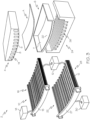
- Fig. 1 is a perspective view of an induction heating system in an assembled condition disposed between press platens.
- Fig. 2 is a perspective view of the induction heating system of Fig. 1 further showing removed armature-supported induction coil arrays.
- Fig. 3 is an exploded perspective view of the induction heating system of Fig. 1 further showing metallic susceptors that are part of molds of the induction heating system.
- Fig. 4 is an exploded perspective view of a variation of induction heating system of Fig. 3 further showing metallic susceptors that are adjacent to the molds of the induction heating system.
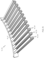
- Fig. 5 is a first perspective view of an armature-supported induction coil array.
- Fig. 1 is a perspective view of an induction heating system in an assembled condition disposed between press platens.
- Fig. 2 is a perspective view of the induction heating system of Fig. 1 further showing removed armature-supported induction coil arrays.
- Fig. 3 is an exploded perspective view
- FIG. 6 is a second perspective view of the armature-supported induction coil array of Fig. 5 .
- Fig. 7 is a third perspective view of the armature-supported induction coil array of Fig. 5 .
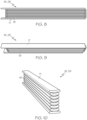
- Fig. 8 is a side view of a finger of the armature-supported induction coil array.
- Fig. 9 is a first perspective view of the finger of Fig. 8.
- Fig. 10 is a second perspective view of the finger of Fig. 8 .
- the induction heating system 2 includes a first mold 4 and a second mold 6 defining a mold cavity therebetween, a first metallic susceptor 8 as part of the first mold 4, a first armature-supported induction coil array 10 in proximity to the first metallic susceptor 8, and a first induction generator 12 electrically coupled with the first armature-supported induction coil array 10.
- Fig. 4 is a variation of Fig. 3 in which the first metallic susceptor 8 is adjacent to the first mold 4.
- first mold 4 and second mold 6 are illustrated as providing a simple-shaped mold cavity therebetween, the present description facilitates molding of complex contoured articles.
- the first mold 4 includes a plurality of first slots 14.
- the first armature-supported induction coil array 10 is shown as a modular induction coil comprising a plurality of first fingers 16 positionable within the plurality of first slots 14. Accordingly, by providing the plurality of first slots 14 in the first mold 4 and the plurality of first fingers 16 in the first armature-supported induction coil array 10, the induction heating system 2 facilitates removal of the first armature-supported induction coil array 10 from the first mold 4.
- the first armature-supported induction coil array 10 may include an endcap 15 supporting the plurality of first fingers 16.
- the induction heating system 2 facilitates air cooling, e.g. passive air cooling, of the thermoplastic article A and the first armature-supported induction coil array 10. Also, the separated finger structure of the first armature-supported induction coil array 10 facilitates faster air cooling by permitting convection of area between each of the plurality of first fingers 16.
- the first armature-supported induction coil array 10 can be removed and placed into another tool as needed. This modularity reduced the total cost and complexity of the molding tool. Additionally, by making the first armature-supported induction coil array 10 as a plurality first fingers 16, the first armature-supported induction coil array 10 can be shaped to best approximate the contour of the lowermost surface 5 of the first mold 4 for more efficient inductive coupling.
- the induction heating system 2 includes a first magnetic hysteresis detector 18 associated with the first armature-supported induction coil array 10.
- a magnetic hysteresis from the inductively heated first metallic susceptor 8 can be detected.
- a frequency generated by the first induction generator 12 can be adjusted to minimize heating of the first armature-supported induction coil array 10.
- the adjustment of the frequency generated by the first induction generator 12 may frequency match the magnetic hysteresis from the inductively heated first metallic susceptor 8.
- Heating the first metallic susceptor 8 by this frequency matching induction generation can minimize heat generated in the first armature-supported induction coil array 10.
- the adjustment of the frequency generated by the first induction generator 12 may be performed, for example, by using a controller (not shown), which may be computer hardware device.
- the controller may be communicatively coupled to the first magnetic hysteresis detector 18 and the first induction generator 12.
- the above-described feature of the first magnetic hysteresis detector 18 may be employed in combination with the first armature-supported induction coil array 10 having the plurality of first fingers 16.
- the induction heating system 2 includes a second metallic susceptor 20 as part of the second mold 6.
- Fig. 4 is a variation of Fig. 3 in which the second metallic susceptor 20 is adjacent to the second mold 6.
- the induction heating system 2 facilitates use of the induction heating system 2 to heat the thermoplastic article A from both sides of the thermoplastic article A.
- the first metallic susceptor 8 is part of the first mold 4 while the second metallic susceptor 20 is adjacent to the second mold 6.
- the first metallic susceptor 8 is adjacent to the first mold 4 while the second metallic susceptor 20 is part of the second mold 6.
- second metallic susceptor may be employed in combination with the first armature-supported induction coil array 10 having the plurality of first fingers 16.
- the induction heating system 2 includes a second armature-supported induction coil array 22 shown as a modular induction coil in proximity to the second metallic susceptor 20.
- a heating of the second metallic susceptor 20 by the second armature-supported induction coil array 22 may be independently controlled from the heating of the first metallic susceptor 8 by the first armature-supported induction coil array 10.
- the first induction generator 12 can be electrically coupled with the second armature-supported induction coil array 22.
- the induction heating system 2 may include a second induction generator (not shown) and the second induction generator may be electrically coupled with the second armature-supported induction coil array 22.
- the induction heating system 2 includes a mold support 24 supporting the second mold 6.
- the second mold 6 may have a small overall size.
- the mold support 24 may instead support the first mold 4.
- the second mold 6 forms the second metallic susceptor 20 and the uppermost surface 7 of the second mold 6 preferably forms the second metallic susceptor 20.
- the second metallic susceptor 20 is provided as at least a portion of the second mold 6, a process of assembling the induction heating system 2 for molding the thermoplastic article A may be simplified.
- the second metallic susceptor 20 is positioned adjacent to the second mold 6.
- the second metallic susceptor 20 By providing the second metallic susceptor 20 as being positioned adjacent to the second mold 6, a process of making the second mold 6 and second metallic susceptor 20 may be simplified. Additionally, the second mold 6 may be made entirely of non-conductive materials.
- a variation of the induction heating system 2 includes that at least a portion of the first mold 4 forms the first metallic susceptor 8 while at least a portion of the second mold 6 forms the second metallic susceptor 20. Another variation of the induction heating system 2 includes that at least a portion of the first mold 4 forms the first metallic susceptor 8 while the second metallic susceptor 20 is positioned adjacent to the second mold 6. Yet another variation of the induction heating system 2 includes that the first metallic susceptor 8 is positioned adjacent to the first mold 4 while at least a portion of the second mold 6 forms the second metallic susceptor 20. Yet another variation of the induction heating system 2 includes that the first metallic susceptor 8 is positioned adjacent to the first mold 4 while the second metallic susceptor 20 is positioned adjacent to the second mold 6.
- first metallic susceptor 8 and the second metal susceptor 20 may be employed in combination with any one or more of the features of the induction heating system 2 described above.
- the first metallic susceptor 8 is formed from a smart susceptor material.
- the second metallic susceptor 20 is formed from a smart susceptor material.
- both the first metallic susceptor 8 and the second metallic susceptor 20 are formed from smart susceptor materials.
- a smart susceptor material is a material having a predetermined Curie point causing a reduction of magnetic properties of the material as the material nears the Curie point.
- the smart susceptor material facilitates a limiting temperature to which the material may be inductively heated.
- the smart susceptor material of the first metallic susceptor 8 and the second metallic susceptor 20 includes nickel-iron alloys.
- the temperature to which the first metallic susceptor 8 and/or the second metallic susceptor 20 may be heated is limited, thereby preventing overheating of the thermoplastic article A.
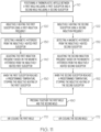
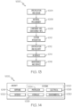
- Fig. 11 is a flow diagram representing a method 100 for molding a thermoplastic article A, such as a thermoplastic composite article.
- the method 100 includes positioning 110 a thermoplastic article A between a first mold 4 including a first metallic susceptor 8 and a second mold 6 including a second metallic susceptor 20, inductively heating 120 the first metallic susceptor 8 using a first induction frequency, detecting a magnetic hysteresis 130 from the inductively heated first metallic susceptor 8, adjusting the first induction frequency 140 based on the magnetic hysteresis from the inductively heated first metallic susceptor 8, and pressing together 160 the first mold 4 and the second mold 6.
- Fig. 11 further includes optional steps shown in dashed lines.
- the steps of positioning, inductively heating, and pressing of the thermoplastic article A between the first mold 4 and the second mold 6 effectuate the process of molding of the thermoplastic article A while the steps of detecting the magnetic hysteresis and adjusting the first induction frequency avoid the need for water cooling of the first mold 4.
- the above-described method 100 may be employed in combination with any of the features of the induction heating system 2 as described above.
- the method 100 includes, inductively heating 122 the second metallic susceptor 20 using a second induction frequency, detecting a magnetic hysteresis 132 from the inductively heated second metallic susceptor 20, and adjusting the second induction frequency 142 based on the magnetic hysteresis from the inductively heated second metallic susceptor 20.
- the method 100 facilitates heating the thermoplastic article A from both sides of the thermoplastic article A and avoids the need for water cooling of the second mold 6.
- steps of inductively heating 122 the second metallic susceptor 20 using a second induction frequency, detecting a magnetic hysteresis 132 from the inductively heated second metallic susceptor 20, and adjusting the second induction frequency 142 based on the magnetic hysteresis from the inductively heated second metallic susceptor 20 may be employed in combination with the step of stopping the inductive heating 150 of the first metallic susceptor 8 and/or with air cooling 170 the first mold 4 and may further be combined with any of the features of the induction heating system 2 as described above.
- the method 100 includes, when the second metallic susceptor 20 reaches a predetermined temperature, stopping the inductive heating 152 of the second metallic susceptor 20.
- the stopping of the inductive heating 152 of the second metallic susceptor 20 may be facilitated by forming the second metallic susceptor 20 from a smart susceptor material.
- the temperature to which the second metallic susceptor 20 may be heated is limited, thereby preventing overheating of the thermoplastic article A.
- the predetermined temperature at which the inductive heating of the first metallic susceptor 8 is stopped is above a curing temperature of the thermoplastic article A.
- the step of stopping the inductive heating 152 of the second metallic susceptor 20 may be employed in combination with any of the previously-describes steps of the method 100 and with any of the features of the induction heating system 2 as described above.
- the modular induction coil may take the form of the first armature-supported induction coil array 10 or the second armature-supported induction coil array 22.
- the metallic susceptor may take the form of the first metallic susceptor 8 or the second metallic susceptor 20.
- detecting a magnetic hysteresis from the inductively heated metallic susceptor 212 may be performed by the first magnetic hysteresis detector 18 or the second magnetic hysteresis detector 30.
- adjusting the first induction frequency based on the magnetic hysteresis from the inductively heated metallic susceptor 213 may be performed using a controller (not shown), which may be computer hardware device.
- Examples of the present disclosure may be described in the context of an aircraft manufacturing and service method 1000, as shown in Fig. 13 , and an aircraft 1002, as shown in Fig. 14 .
- the aircraft manufacturing and service method 1000 may include specification and design 1004 of the aircraft 1002 and material procurement 1006.
- component/subassembly manufacturing 1008 and system integration 1010 of the aircraft 1002 takes place.
- the aircraft 1002 may go through certification and delivery 1012 in order to be placed in service 1014.
- routine maintenance and service 1016 which may also include modification, reconfiguration, refurbishment and the like.
- a system integrator may include without limitation any number of aircraft manufacturers and major-system subcontractors; a third party may include without limitation any number of venders, subcontractors, and suppliers; and an operator may be an airline, leasing company, military entity, service organization, and so on.
- thermoplastic article of the present disclosure may be employed during any one or more of the stages of the aircraft manufacturing and service method 1000, including at least component/subassembly manufacturing 1008, system integration 1010, and routine maintenance and service 1016.
Landscapes
- Physics & Mathematics (AREA)
- Electromagnetism (AREA)
- Health & Medical Sciences (AREA)
- Toxicology (AREA)
- Engineering & Computer Science (AREA)
- Mechanical Engineering (AREA)
- Moulds For Moulding Plastics Or The Like (AREA)
- Heating, Cooling, Or Curing Plastics Or The Like In General (AREA)
- Shaping Of Tube Ends By Bending Or Straightening (AREA)
Claims (15)
- Induktionsheizungssystem (2) zum Formen eines thermoplastischen Artikels (A), umfassend:eine erste Form (4) und eine zweite Form (6), die dazwischen einen Formhohlraum zum Formen des thermoplastischen Artikels (A) definieren;einen ersten metallischen Suszeptor (8) als Teil der ersten Form (4) oder angrenzend an diese;eine erste ankergestützte Induktionsspulenanordnung (10) in der Nähe des ersten metallischen Suszeptors (8); undeinen ersten Induktionsgenerator (12), der mit der ersten ankergestützten Induktionsspulenanordnung (10) elektrisch gekoppelt ist.
- Induktionsheizsystem (2) nach Anspruch 1, wobei die erste Form (4) eine Vielzahl von ersten Schlitzen (14) umfasst und die erste ankergestützte Induktionsspulenanordnung (10) eine Vielzahl von ersten Stäbchen (16) umfasst, die in der Vielzahl von ersten Schlitzen (14) positionierbar sind.
- Induktionsheizsystem (2) nach einem der Ansprüche 1 und 2, das ferner einen ersten magnetischen Hysteresedetektor (18) umfasst, der mit der ersten ankergestützten Induktionsspulenanordnung (10) verknüpft ist.
- Induktionsheizsystem (2) nach einem der Ansprüche 1 bis 3, das ferner einen zweiten metallischen Suszeptor (20) als Teil der zweiten Form (6) oder angrenzend an diese umfasst.
- Induktionsheizsystem (2) nach Anspruch 4, das ferner eine zweite ankergestützte Induktionsspulenanordnung (22) in der Nähe des zweiten metallischen Suszeptors (20) umfasst.
- Induktionsheizsystem (2) nach einem der vorhergehenden Ansprüche, das ferner einen Formträger (24) umfasst, der die zweite Form (6) trägt.
- Induktionsheizsystem (2) nach Anspruch 6, wobei der Formträger (24) eine Vielzahl von zweiten Schlitzen (26) umfasst und die zweite ankergestützte Induktionsspulenanordnung (22) eine Vielzahl von zweiten Stäbchen (28) umfasst, die in der Vielzahl von zweiten Schlitzen (26) positionierbar sind.
- Induktionsheizsystem (2) nach einem der Ansprüche 5 bis 7, das ferner einen zweiten magnetischen Hysteresedetektor (30) umfasst, der mit der zweiten ankergestützten Induktionsspulenanordnung (22) verknüpft ist.
- Induktionsheizsystem (2) nach einem der Ansprüche 1 bis 8, das ferner eine Pressplatte (32) zum Zusammenpressen der ersten Form (4) und der zweiten Form (6) umfasst.
- Verfahren zum Formen eines thermoplastischen Artikels unter Verwendung eines Systems nach einem der vorhergehenden Ansprüche, wobei das Verfahren Folgendes umfasst:Positionieren eines thermoplastischen Artikels zwischen der ersten Form (4) und der zweiten Form (6);induktives Erhitzen des ersten metallischen Suszeptors unter Verwendung einer ersten Induktionsfrequenz;Erfassen einer magnetischen Hysterese des induktiv erhitzten ersten metallischen Suszeptors;Anpassen der ersten Induktionsfrequenz basierend auf der magnetischen Hysterese des induktiv erhitzten ersten metallischen Suszeptors; undZusammenpressen der ersten Form (4) und der zweiten Form (6).
- Verfahren nach Anspruch 10, das ferner Folgendes umfasst:
wenn der erste metallische Suszeptor eine vorbestimmte Temperatur erreicht, Beenden des induktiven Erhitzens des ersten metallischen Suszeptors. - Verfahren nach einem der Ansprüche 10 und 11, das ferner Folgendes umfasst: Luftkühlen der ersten Form.
- Verfahren nach einem der Ansprüche 10 bis 12, das ferner Folgendes umfasst:induktives Erhitzen des zweiten metallischen Suszeptors unter Verwendung einer zweiten Induktionsfrequenz;Erfassen einer magnetischen Hysterese des induktiv erhitzten zweiten metallischen Suszeptors; undAnpassen der zweiten Induktionsfrequenz basierend auf der magnetischen Hysterese des induktiv erhitzten zweiten metallischen Suszeptors.
- Verfahren nach Anspruch 13, das ferner Folgendes umfasst:
wenn der zweite metallische Suszeptor eine vorbestimmte Temperatur erreicht, Beenden des induktiven Erhitzens des zweiten metallischen Suszeptors. - Verfahren nach einem Ansprüche 13 bis 14, das ferner Folgendes umfasst:
Luftkühlen der zweiten Form.
Priority Applications (2)
| Application Number | Priority Date | Filing Date | Title |
|---|---|---|---|
| EP22174813.0A EP4072243B1 (de) | 2018-12-12 | 2019-11-19 | Induktionsheizsystem zum formen eines thermoplastischen artikels und verfahren zum formen eines thermoplastischen artikels |
| EP24170154.9A EP4376548A3 (de) | 2018-12-12 | 2019-11-19 | Induktionsheizsystem zum formen eines thermoplastischen artikels und verfahren zum formen eines thermoplastischen artikels |
Applications Claiming Priority (1)
| Application Number | Priority Date | Filing Date | Title |
|---|---|---|---|
| US16/217,276 US10981300B2 (en) | 2018-12-12 | 2018-12-12 | Induction heating system for molding a thermoplastic article and method for molding a thermoplastic article |
Related Child Applications (3)
| Application Number | Title | Priority Date | Filing Date |
|---|---|---|---|
| EP22174813.0A Division-Into EP4072243B1 (de) | 2018-12-12 | 2019-11-19 | Induktionsheizsystem zum formen eines thermoplastischen artikels und verfahren zum formen eines thermoplastischen artikels |
| EP22174813.0A Division EP4072243B1 (de) | 2018-12-12 | 2019-11-19 | Induktionsheizsystem zum formen eines thermoplastischen artikels und verfahren zum formen eines thermoplastischen artikels |
| EP24170154.9A Division EP4376548A3 (de) | 2018-12-12 | 2019-11-19 | Induktionsheizsystem zum formen eines thermoplastischen artikels und verfahren zum formen eines thermoplastischen artikels |
Publications (3)
| Publication Number | Publication Date |
|---|---|
| EP3668273A2 EP3668273A2 (de) | 2020-06-17 |
| EP3668273A3 EP3668273A3 (de) | 2020-09-02 |
| EP3668273B1 true EP3668273B1 (de) | 2023-07-19 |
Family
ID=68731659
Family Applications (3)
| Application Number | Title | Priority Date | Filing Date |
|---|---|---|---|
| EP24170154.9A Pending EP4376548A3 (de) | 2018-12-12 | 2019-11-19 | Induktionsheizsystem zum formen eines thermoplastischen artikels und verfahren zum formen eines thermoplastischen artikels |
| EP22174813.0A Active EP4072243B1 (de) | 2018-12-12 | 2019-11-19 | Induktionsheizsystem zum formen eines thermoplastischen artikels und verfahren zum formen eines thermoplastischen artikels |
| EP19210031.1A Active EP3668273B1 (de) | 2018-12-12 | 2019-11-19 | Induktionsheizungssystem zum formen eines thermoplastischen artikels und verfahren zum formen eines thermoplastischen artikels |
Family Applications Before (2)
| Application Number | Title | Priority Date | Filing Date |
|---|---|---|---|
| EP24170154.9A Pending EP4376548A3 (de) | 2018-12-12 | 2019-11-19 | Induktionsheizsystem zum formen eines thermoplastischen artikels und verfahren zum formen eines thermoplastischen artikels |
| EP22174813.0A Active EP4072243B1 (de) | 2018-12-12 | 2019-11-19 | Induktionsheizsystem zum formen eines thermoplastischen artikels und verfahren zum formen eines thermoplastischen artikels |
Country Status (6)
| Country | Link |
|---|---|
| US (1) | US10981300B2 (de) |
| EP (3) | EP4376548A3 (de) |
| AU (1) | AU2019279970B2 (de) |
| CA (1) | CA3059763A1 (de) |
| ES (2) | ES2960037T3 (de) |
| PT (2) | PT4072243T (de) |
Families Citing this family (1)
| Publication number | Priority date | Publication date | Assignee | Title |
|---|---|---|---|---|
| CN112822950B (zh) * | 2018-09-25 | 2024-09-24 | 菲利普莫里斯生产公司 | 用于感应加热气溶胶形成基材的感受器组件 |
Family Cites Families (12)
| Publication number | Priority date | Publication date | Assignee | Title |
|---|---|---|---|---|
| DE19843087A1 (de) * | 1998-09-21 | 2000-03-23 | Didier Werke Ag | Induktor zur Erzeugung eines elektromagnetischen Wechselfeldes |
| US6455825B1 (en) * | 2000-11-21 | 2002-09-24 | Sandia Corporation | Use of miniature magnetic sensors for real-time control of the induction heating process |
| US6566635B1 (en) | 2002-03-08 | 2003-05-20 | The Boeing Company | Smart susceptor having a geometrically complex molding surface |
| FR2867939B1 (fr) * | 2004-03-18 | 2007-08-10 | Roctool | Procede pour chauffer des materiaux en vue de produire des objets et dispositif mettant en oeuvre de procede |
| US8021135B2 (en) | 2007-06-08 | 2011-09-20 | Sabic Innovative Plastics Ip B.V. | Mold apparatus for forming polymer and method |
| US8375758B1 (en) | 2007-09-13 | 2013-02-19 | The Boeing Company | Induction forming of metal components with slotted susceptors |
| US8383998B1 (en) | 2009-11-02 | 2013-02-26 | The Boeing Company | Tooling inserts for laminated tooling |
| US9259886B2 (en) | 2009-12-15 | 2016-02-16 | The Boeing Company | Curing composites out-of-autoclave using induction heating with smart susceptors |
| CN102407594B (zh) * | 2010-09-17 | 2014-11-05 | 本田技研工业株式会社 | 成形装置及成形方法 |
| US9586362B2 (en) | 2011-05-17 | 2017-03-07 | The Boeing Company | Thermoplastic welding apparatus and method |
| US9820339B2 (en) | 2011-09-29 | 2017-11-14 | The Boeing Company | Induction heating using induction coils in series-parallel circuits |
| US9635714B2 (en) | 2013-05-06 | 2017-04-25 | The Boeing Company | Incremental sheet forming for fabrication of cold sprayed smart susceptor |
-
2018
- 2018-12-12 US US16/217,276 patent/US10981300B2/en active Active
-
2019
- 2019-10-23 CA CA3059763A patent/CA3059763A1/en active Pending
- 2019-11-19 ES ES19210031T patent/ES2960037T3/es active Active
- 2019-11-19 ES ES22174813T patent/ES2994513T3/es active Active
- 2019-11-19 PT PT221748130T patent/PT4072243T/pt unknown
- 2019-11-19 EP EP24170154.9A patent/EP4376548A3/de active Pending
- 2019-11-19 EP EP22174813.0A patent/EP4072243B1/de active Active
- 2019-11-19 PT PT192100311T patent/PT3668273T/pt unknown
- 2019-11-19 EP EP19210031.1A patent/EP3668273B1/de active Active
- 2019-12-11 AU AU2019279970A patent/AU2019279970B2/en active Active
Also Published As
| Publication number | Publication date |
|---|---|
| US20200189148A1 (en) | 2020-06-18 |
| PT3668273T (pt) | 2023-08-24 |
| PT4072243T (pt) | 2024-10-15 |
| CA3059763A1 (en) | 2020-06-12 |
| US10981300B2 (en) | 2021-04-20 |
| AU2019279970A1 (en) | 2020-07-02 |
| EP3668273A3 (de) | 2020-09-02 |
| EP3668273A2 (de) | 2020-06-17 |
| EP4376548A2 (de) | 2024-05-29 |
| ES2994513T3 (en) | 2025-01-24 |
| ES2960037T3 (es) | 2024-02-29 |
| EP4072243B1 (de) | 2024-09-04 |
| AU2019279970B2 (en) | 2025-04-10 |
| EP4376548A3 (de) | 2024-08-28 |
| EP4072243A1 (de) | 2022-10-12 |
Similar Documents
| Publication | Publication Date | Title |
|---|---|---|
| EP2547501B1 (de) | Verfahren und vorrichtung zum härten einer verbundteillaminierung | |
| US10000026B2 (en) | Composite induction consolidation apparatus and method | |
| US8556619B2 (en) | Composite fabrication apparatus | |
| EP2806711B1 (de) | Inkrementelle Blechumformung zur Herstellung eines kaltgasgespritzten intelligenten Suszeptors | |
| US9314975B1 (en) | High rate fabrication of compression molded components | |
| JP7403011B2 (ja) | 熱可塑性部分を有する部品のための誘導加熱成形 | |
| US8375758B1 (en) | Induction forming of metal components with slotted susceptors | |
| EP2909012B1 (de) | Nachgiebige schicht für angepasste werkzeugformung von unebenen verbundstoffvorformen | |
| EP3668273B1 (de) | Induktionsheizungssystem zum formen eines thermoplastischen artikels und verfahren zum formen eines thermoplastischen artikels | |
| EP3666487B1 (de) | Verfahren zum härten von duroplastischen verbundwerkstoffen | |
| US10201959B2 (en) | Gradient curing of composite laminate parts | |
| US20250261288A1 (en) | Tailored leveling temperature for low temperature expansion iron nickel alloys |
Legal Events
| Date | Code | Title | Description |
|---|---|---|---|
| PUAI | Public reference made under article 153(3) epc to a published international application that has entered the european phase |
Free format text: ORIGINAL CODE: 0009012 |
|
| STAA | Information on the status of an ep patent application or granted ep patent |
Free format text: STATUS: THE APPLICATION HAS BEEN PUBLISHED |
|
| AK | Designated contracting states |
Kind code of ref document: A2 Designated state(s): AL AT BE BG CH CY CZ DE DK EE ES FI FR GB GR HR HU IE IS IT LI LT LU LV MC MK MT NL NO PL PT RO RS SE SI SK SM TR |
|
| AX | Request for extension of the european patent |
Extension state: BA ME |
|
| PUAL | Search report despatched |
Free format text: ORIGINAL CODE: 0009013 |
|
| AK | Designated contracting states |
Kind code of ref document: A3 Designated state(s): AL AT BE BG CH CY CZ DE DK EE ES FI FR GB GR HR HU IE IS IT LI LT LU LV MC MK MT NL NO PL PT RO RS SE SI SK SM TR |
|
| AX | Request for extension of the european patent |
Extension state: BA ME |
|
| RIC1 | Information provided on ipc code assigned before grant |
Ipc: H05B 6/10 20060101AFI20200728BHEP |
|
| STAA | Information on the status of an ep patent application or granted ep patent |
Free format text: STATUS: REQUEST FOR EXAMINATION WAS MADE |
|
| 17P | Request for examination filed |
Effective date: 20210225 |
|
| RBV | Designated contracting states (corrected) |
Designated state(s): AL AT BE BG CH CY CZ DE DK EE ES FI FR GB GR HR HU IE IS IT LI LT LU LV MC MK MT NL NO PL PT RO RS SE SI SK SM TR |
|
| RIN1 | Information on inventor provided before grant (corrected) |
Inventor name: GRAY, EVERETTE D. |
|
| GRAP | Despatch of communication of intention to grant a patent |
Free format text: ORIGINAL CODE: EPIDOSNIGR1 |
|
| STAA | Information on the status of an ep patent application or granted ep patent |
Free format text: STATUS: GRANT OF PATENT IS INTENDED |
|
| INTG | Intention to grant announced |
Effective date: 20211006 |
|
| RIN1 | Information on inventor provided before grant (corrected) |
Inventor name: GRAY, EVERETTE D. |
|
| GRAJ | Information related to disapproval of communication of intention to grant by the applicant or resumption of examination proceedings by the epo deleted |
Free format text: ORIGINAL CODE: EPIDOSDIGR1 |
|
| STAA | Information on the status of an ep patent application or granted ep patent |
Free format text: STATUS: REQUEST FOR EXAMINATION WAS MADE |
|
| STAA | Information on the status of an ep patent application or granted ep patent |
Free format text: STATUS: EXAMINATION IS IN PROGRESS |
|
| INTC | Intention to grant announced (deleted) | ||
| 17Q | First examination report despatched |
Effective date: 20220311 |
|
| GRAP | Despatch of communication of intention to grant a patent |
Free format text: ORIGINAL CODE: EPIDOSNIGR1 |
|
| STAA | Information on the status of an ep patent application or granted ep patent |
Free format text: STATUS: GRANT OF PATENT IS INTENDED |
|
| INTG | Intention to grant announced |
Effective date: 20230221 |
|
| RAP3 | Party data changed (applicant data changed or rights of an application transferred) |
Owner name: THE BOEING COMPANY |
|
| GRAS | Grant fee paid |
Free format text: ORIGINAL CODE: EPIDOSNIGR3 |
|
| GRAA | (expected) grant |
Free format text: ORIGINAL CODE: 0009210 |
|
| STAA | Information on the status of an ep patent application or granted ep patent |
Free format text: STATUS: THE PATENT HAS BEEN GRANTED |
|
| AK | Designated contracting states |
Kind code of ref document: B1 Designated state(s): AL AT BE BG CH CY CZ DE DK EE ES FI FR GB GR HR HU IE IS IT LI LT LU LV MC MK MT NL NO PL PT RO RS SE SI SK SM TR |
|
| REG | Reference to a national code |
Ref country code: GB Ref legal event code: FG4D |
|
| REG | Reference to a national code |
Ref country code: CH Ref legal event code: EP |
|
| REG | Reference to a national code |
Ref country code: DE Ref legal event code: R096 Ref document number: 602019032935 Country of ref document: DE |
|
| P01 | Opt-out of the competence of the unified patent court (upc) registered |
Effective date: 20230703 |
|
| REG | Reference to a national code |
Ref country code: IE Ref legal event code: FG4D |
|
| REG | Reference to a national code |
Ref country code: PT Ref legal event code: SC4A Ref document number: 3668273 Country of ref document: PT Date of ref document: 20230824 Kind code of ref document: T Free format text: AVAILABILITY OF NATIONAL TRANSLATION Effective date: 20230821 |
|
| REG | Reference to a national code |
Ref country code: SE Ref legal event code: TRGR |
|
| REG | Reference to a national code |
Ref country code: LT Ref legal event code: MG9D |
|
| REG | Reference to a national code |
Ref country code: NL Ref legal event code: MP Effective date: 20230719 |
|
| REG | Reference to a national code |
Ref country code: AT Ref legal event code: MK05 Ref document number: 1590779 Country of ref document: AT Kind code of ref document: T Effective date: 20230719 |
|
| PG25 | Lapsed in a contracting state [announced via postgrant information from national office to epo] |
Ref country code: NL Free format text: LAPSE BECAUSE OF FAILURE TO SUBMIT A TRANSLATION OF THE DESCRIPTION OR TO PAY THE FEE WITHIN THE PRESCRIBED TIME-LIMIT Effective date: 20230719 |
|
| PG25 | Lapsed in a contracting state [announced via postgrant information from national office to epo] |
Ref country code: GR Free format text: LAPSE BECAUSE OF FAILURE TO SUBMIT A TRANSLATION OF THE DESCRIPTION OR TO PAY THE FEE WITHIN THE PRESCRIBED TIME-LIMIT Effective date: 20231020 |
|
| PG25 | Lapsed in a contracting state [announced via postgrant information from national office to epo] |
Ref country code: IS Free format text: LAPSE BECAUSE OF FAILURE TO SUBMIT A TRANSLATION OF THE DESCRIPTION OR TO PAY THE FEE WITHIN THE PRESCRIBED TIME-LIMIT Effective date: 20231119 |
|
| PG25 | Lapsed in a contracting state [announced via postgrant information from national office to epo] |
Ref country code: RS Free format text: LAPSE BECAUSE OF FAILURE TO SUBMIT A TRANSLATION OF THE DESCRIPTION OR TO PAY THE FEE WITHIN THE PRESCRIBED TIME-LIMIT Effective date: 20230719 Ref country code: NO Free format text: LAPSE BECAUSE OF FAILURE TO SUBMIT A TRANSLATION OF THE DESCRIPTION OR TO PAY THE FEE WITHIN THE PRESCRIBED TIME-LIMIT Effective date: 20231019 Ref country code: LV Free format text: LAPSE BECAUSE OF FAILURE TO SUBMIT A TRANSLATION OF THE DESCRIPTION OR TO PAY THE FEE WITHIN THE PRESCRIBED TIME-LIMIT Effective date: 20230719 Ref country code: LT Free format text: LAPSE BECAUSE OF FAILURE TO SUBMIT A TRANSLATION OF THE DESCRIPTION OR TO PAY THE FEE WITHIN THE PRESCRIBED TIME-LIMIT Effective date: 20230719 Ref country code: IS Free format text: LAPSE BECAUSE OF FAILURE TO SUBMIT A TRANSLATION OF THE DESCRIPTION OR TO PAY THE FEE WITHIN THE PRESCRIBED TIME-LIMIT Effective date: 20231119 Ref country code: HR Free format text: LAPSE BECAUSE OF FAILURE TO SUBMIT A TRANSLATION OF THE DESCRIPTION OR TO PAY THE FEE WITHIN THE PRESCRIBED TIME-LIMIT Effective date: 20230719 Ref country code: GR Free format text: LAPSE BECAUSE OF FAILURE TO SUBMIT A TRANSLATION OF THE DESCRIPTION OR TO PAY THE FEE WITHIN THE PRESCRIBED TIME-LIMIT Effective date: 20231020 Ref country code: FI Free format text: LAPSE BECAUSE OF FAILURE TO SUBMIT A TRANSLATION OF THE DESCRIPTION OR TO PAY THE FEE WITHIN THE PRESCRIBED TIME-LIMIT Effective date: 20230719 Ref country code: AT Free format text: LAPSE BECAUSE OF FAILURE TO SUBMIT A TRANSLATION OF THE DESCRIPTION OR TO PAY THE FEE WITHIN THE PRESCRIBED TIME-LIMIT Effective date: 20230719 |
|
| PG25 | Lapsed in a contracting state [announced via postgrant information from national office to epo] |
Ref country code: PL Free format text: LAPSE BECAUSE OF FAILURE TO SUBMIT A TRANSLATION OF THE DESCRIPTION OR TO PAY THE FEE WITHIN THE PRESCRIBED TIME-LIMIT Effective date: 20230719 |
|
| REG | Reference to a national code |
Ref country code: ES Ref legal event code: FG2A Ref document number: 2960037 Country of ref document: ES Kind code of ref document: T3 Effective date: 20240229 |
|
| REG | Reference to a national code |
Ref country code: DE Ref legal event code: R097 Ref document number: 602019032935 Country of ref document: DE |
|
| PG25 | Lapsed in a contracting state [announced via postgrant information from national office to epo] |
Ref country code: SM Free format text: LAPSE BECAUSE OF FAILURE TO SUBMIT A TRANSLATION OF THE DESCRIPTION OR TO PAY THE FEE WITHIN THE PRESCRIBED TIME-LIMIT Effective date: 20230719 Ref country code: RO Free format text: LAPSE BECAUSE OF FAILURE TO SUBMIT A TRANSLATION OF THE DESCRIPTION OR TO PAY THE FEE WITHIN THE PRESCRIBED TIME-LIMIT Effective date: 20230719 Ref country code: EE Free format text: LAPSE BECAUSE OF FAILURE TO SUBMIT A TRANSLATION OF THE DESCRIPTION OR TO PAY THE FEE WITHIN THE PRESCRIBED TIME-LIMIT Effective date: 20230719 Ref country code: DK Free format text: LAPSE BECAUSE OF FAILURE TO SUBMIT A TRANSLATION OF THE DESCRIPTION OR TO PAY THE FEE WITHIN THE PRESCRIBED TIME-LIMIT Effective date: 20230719 Ref country code: CZ Free format text: LAPSE BECAUSE OF FAILURE TO SUBMIT A TRANSLATION OF THE DESCRIPTION OR TO PAY THE FEE WITHIN THE PRESCRIBED TIME-LIMIT Effective date: 20230719 Ref country code: SK Free format text: LAPSE BECAUSE OF FAILURE TO SUBMIT A TRANSLATION OF THE DESCRIPTION OR TO PAY THE FEE WITHIN THE PRESCRIBED TIME-LIMIT Effective date: 20230719 |
|
| PLBE | No opposition filed within time limit |
Free format text: ORIGINAL CODE: 0009261 |
|
| STAA | Information on the status of an ep patent application or granted ep patent |
Free format text: STATUS: NO OPPOSITION FILED WITHIN TIME LIMIT |
|
| 26N | No opposition filed |
Effective date: 20240422 |
|
| REG | Reference to a national code |
Ref country code: CH Ref legal event code: PL |
|
| PG25 | Lapsed in a contracting state [announced via postgrant information from national office to epo] |
Ref country code: MC Free format text: LAPSE BECAUSE OF FAILURE TO SUBMIT A TRANSLATION OF THE DESCRIPTION OR TO PAY THE FEE WITHIN THE PRESCRIBED TIME-LIMIT Effective date: 20230719 |
|
| PG25 | Lapsed in a contracting state [announced via postgrant information from national office to epo] |
Ref country code: LU Free format text: LAPSE BECAUSE OF NON-PAYMENT OF DUE FEES Effective date: 20231119 |
|
| PG25 | Lapsed in a contracting state [announced via postgrant information from national office to epo] |
Ref country code: CH Free format text: LAPSE BECAUSE OF NON-PAYMENT OF DUE FEES Effective date: 20231130 |
|
| PG25 | Lapsed in a contracting state [announced via postgrant information from national office to epo] |
Ref country code: MC Free format text: LAPSE BECAUSE OF FAILURE TO SUBMIT A TRANSLATION OF THE DESCRIPTION OR TO PAY THE FEE WITHIN THE PRESCRIBED TIME-LIMIT Effective date: 20230719 Ref country code: LU Free format text: LAPSE BECAUSE OF NON-PAYMENT OF DUE FEES Effective date: 20231119 Ref country code: CH Free format text: LAPSE BECAUSE OF NON-PAYMENT OF DUE FEES Effective date: 20231130 Ref country code: SI Free format text: LAPSE BECAUSE OF FAILURE TO SUBMIT A TRANSLATION OF THE DESCRIPTION OR TO PAY THE FEE WITHIN THE PRESCRIBED TIME-LIMIT Effective date: 20230719 |
|
| REG | Reference to a national code |
Ref country code: BE Ref legal event code: MM Effective date: 20231130 |
|
| REG | Reference to a national code |
Ref country code: IE Ref legal event code: MM4A |
|
| PG25 | Lapsed in a contracting state [announced via postgrant information from national office to epo] |
Ref country code: IE Free format text: LAPSE BECAUSE OF NON-PAYMENT OF DUE FEES Effective date: 20231119 |
|
| PG25 | Lapsed in a contracting state [announced via postgrant information from national office to epo] |
Ref country code: BE Free format text: LAPSE BECAUSE OF NON-PAYMENT OF DUE FEES Effective date: 20231130 |
|
| PG25 | Lapsed in a contracting state [announced via postgrant information from national office to epo] |
Ref country code: IE Free format text: LAPSE BECAUSE OF NON-PAYMENT OF DUE FEES Effective date: 20231119 Ref country code: BE Free format text: LAPSE BECAUSE OF NON-PAYMENT OF DUE FEES Effective date: 20231130 |
|
| PG25 | Lapsed in a contracting state [announced via postgrant information from national office to epo] |
Ref country code: BG Free format text: LAPSE BECAUSE OF FAILURE TO SUBMIT A TRANSLATION OF THE DESCRIPTION OR TO PAY THE FEE WITHIN THE PRESCRIBED TIME-LIMIT Effective date: 20230719 |
|
| PG25 | Lapsed in a contracting state [announced via postgrant information from national office to epo] |
Ref country code: BG Free format text: LAPSE BECAUSE OF FAILURE TO SUBMIT A TRANSLATION OF THE DESCRIPTION OR TO PAY THE FEE WITHIN THE PRESCRIBED TIME-LIMIT Effective date: 20230719 |
|
| PG25 | Lapsed in a contracting state [announced via postgrant information from national office to epo] |
Ref country code: CY Free format text: LAPSE BECAUSE OF FAILURE TO SUBMIT A TRANSLATION OF THE DESCRIPTION OR TO PAY THE FEE WITHIN THE PRESCRIBED TIME-LIMIT; INVALID AB INITIO Effective date: 20191119 |
|
| PG25 | Lapsed in a contracting state [announced via postgrant information from national office to epo] |
Ref country code: HU Free format text: LAPSE BECAUSE OF FAILURE TO SUBMIT A TRANSLATION OF THE DESCRIPTION OR TO PAY THE FEE WITHIN THE PRESCRIBED TIME-LIMIT; INVALID AB INITIO Effective date: 20191119 |
|
| PGFP | Annual fee paid to national office [announced via postgrant information from national office to epo] |
Ref country code: PT Payment date: 20251106 Year of fee payment: 7 |
|
| PGFP | Annual fee paid to national office [announced via postgrant information from national office to epo] |
Ref country code: DE Payment date: 20251128 Year of fee payment: 7 |
|
| PGFP | Annual fee paid to national office [announced via postgrant information from national office to epo] |
Ref country code: GB Payment date: 20251127 Year of fee payment: 7 |
|
| PGFP | Annual fee paid to national office [announced via postgrant information from national office to epo] |
Ref country code: IT Payment date: 20251119 Year of fee payment: 7 |
|
| PGFP | Annual fee paid to national office [announced via postgrant information from national office to epo] |
Ref country code: FR Payment date: 20251125 Year of fee payment: 7 |
|
| PGFP | Annual fee paid to national office [announced via postgrant information from national office to epo] |
Ref country code: TR Payment date: 20251104 Year of fee payment: 7 |
|
| PGFP | Annual fee paid to national office [announced via postgrant information from national office to epo] |
Ref country code: SE Payment date: 20251127 Year of fee payment: 7 |
|
| PGFP | Annual fee paid to national office [announced via postgrant information from national office to epo] |
Ref country code: ES Payment date: 20251201 Year of fee payment: 7 |